EP3272566B1 - Fahrzeug mit einem fahrzeugtank und armierung für einen fahrzeugtank - Google Patents
Fahrzeug mit einem fahrzeugtank und armierung für einen fahrzeugtank Download PDFInfo
- Publication number
- EP3272566B1 EP3272566B1 EP17181220.9A EP17181220A EP3272566B1 EP 3272566 B1 EP3272566 B1 EP 3272566B1 EP 17181220 A EP17181220 A EP 17181220A EP 3272566 B1 EP3272566 B1 EP 3272566B1
- Authority
- EP
- European Patent Office
- Prior art keywords
- reinforcement
- tank
- vehicle
- wall
- shield
- Prior art date
- Legal status (The legal status is an assumption and is not a legal conclusion. Google has not performed a legal analysis and makes no representation as to the accuracy of the status listed.)
- Active
Links
Images



Classifications
-
- B—PERFORMING OPERATIONS; TRANSPORTING
- B60—VEHICLES IN GENERAL
- B60K—ARRANGEMENT OR MOUNTING OF PROPULSION UNITS OR OF TRANSMISSIONS IN VEHICLES; ARRANGEMENT OR MOUNTING OF PLURAL DIVERSE PRIME-MOVERS IN VEHICLES; AUXILIARY DRIVES FOR VEHICLES; INSTRUMENTATION OR DASHBOARDS FOR VEHICLES; ARRANGEMENTS IN CONNECTION WITH COOLING, AIR INTAKE, GAS EXHAUST OR FUEL SUPPLY OF PROPULSION UNITS IN VEHICLES
- B60K15/00—Arrangement in connection with fuel supply of combustion engines or other fuel consuming energy converters, e.g. fuel cells; Mounting or construction of fuel tanks
- B60K15/03—Fuel tanks
- B60K15/063—Arrangement of tanks
- B60K15/067—Mounting of tanks
- B60K15/07—Mounting of tanks of gas tanks
-
- B—PERFORMING OPERATIONS; TRANSPORTING
- B60—VEHICLES IN GENERAL
- B60K—ARRANGEMENT OR MOUNTING OF PROPULSION UNITS OR OF TRANSMISSIONS IN VEHICLES; ARRANGEMENT OR MOUNTING OF PLURAL DIVERSE PRIME-MOVERS IN VEHICLES; AUXILIARY DRIVES FOR VEHICLES; INSTRUMENTATION OR DASHBOARDS FOR VEHICLES; ARRANGEMENTS IN CONNECTION WITH COOLING, AIR INTAKE, GAS EXHAUST OR FUEL SUPPLY OF PROPULSION UNITS IN VEHICLES
- B60K15/00—Arrangement in connection with fuel supply of combustion engines or other fuel consuming energy converters, e.g. fuel cells; Mounting or construction of fuel tanks
- B60K15/03—Fuel tanks
- B60K15/063—Arrangement of tanks
- B60K15/067—Mounting of tanks
-
- B—PERFORMING OPERATIONS; TRANSPORTING
- B60—VEHICLES IN GENERAL
- B60K—ARRANGEMENT OR MOUNTING OF PROPULSION UNITS OR OF TRANSMISSIONS IN VEHICLES; ARRANGEMENT OR MOUNTING OF PLURAL DIVERSE PRIME-MOVERS IN VEHICLES; AUXILIARY DRIVES FOR VEHICLES; INSTRUMENTATION OR DASHBOARDS FOR VEHICLES; ARRANGEMENTS IN CONNECTION WITH COOLING, AIR INTAKE, GAS EXHAUST OR FUEL SUPPLY OF PROPULSION UNITS IN VEHICLES
- B60K15/00—Arrangement in connection with fuel supply of combustion engines or other fuel consuming energy converters, e.g. fuel cells; Mounting or construction of fuel tanks
- B60K15/03—Fuel tanks
- B60K15/03006—Gas tanks
-
- B—PERFORMING OPERATIONS; TRANSPORTING
- B60—VEHICLES IN GENERAL
- B60K—ARRANGEMENT OR MOUNTING OF PROPULSION UNITS OR OF TRANSMISSIONS IN VEHICLES; ARRANGEMENT OR MOUNTING OF PLURAL DIVERSE PRIME-MOVERS IN VEHICLES; AUXILIARY DRIVES FOR VEHICLES; INSTRUMENTATION OR DASHBOARDS FOR VEHICLES; ARRANGEMENTS IN CONNECTION WITH COOLING, AIR INTAKE, GAS EXHAUST OR FUEL SUPPLY OF PROPULSION UNITS IN VEHICLES
- B60K15/00—Arrangement in connection with fuel supply of combustion engines or other fuel consuming energy converters, e.g. fuel cells; Mounting or construction of fuel tanks
- B60K15/03—Fuel tanks
- B60K15/03177—Fuel tanks made of non-metallic material, e.g. plastics, or of a combination of non-metallic and metallic material
-
- B—PERFORMING OPERATIONS; TRANSPORTING
- B60—VEHICLES IN GENERAL
- B60K—ARRANGEMENT OR MOUNTING OF PROPULSION UNITS OR OF TRANSMISSIONS IN VEHICLES; ARRANGEMENT OR MOUNTING OF PLURAL DIVERSE PRIME-MOVERS IN VEHICLES; AUXILIARY DRIVES FOR VEHICLES; INSTRUMENTATION OR DASHBOARDS FOR VEHICLES; ARRANGEMENTS IN CONNECTION WITH COOLING, AIR INTAKE, GAS EXHAUST OR FUEL SUPPLY OF PROPULSION UNITS IN VEHICLES
- B60K15/00—Arrangement in connection with fuel supply of combustion engines or other fuel consuming energy converters, e.g. fuel cells; Mounting or construction of fuel tanks
- B60K15/03—Fuel tanks
- B60K2015/03032—Manufacturing of fuel tanks
- B60K2015/03046—Manufacturing of fuel tanks made from more than one layer
-
- B—PERFORMING OPERATIONS; TRANSPORTING
- B60—VEHICLES IN GENERAL
- B60K—ARRANGEMENT OR MOUNTING OF PROPULSION UNITS OR OF TRANSMISSIONS IN VEHICLES; ARRANGEMENT OR MOUNTING OF PLURAL DIVERSE PRIME-MOVERS IN VEHICLES; AUXILIARY DRIVES FOR VEHICLES; INSTRUMENTATION OR DASHBOARDS FOR VEHICLES; ARRANGEMENTS IN CONNECTION WITH COOLING, AIR INTAKE, GAS EXHAUST OR FUEL SUPPLY OF PROPULSION UNITS IN VEHICLES
- B60K15/00—Arrangement in connection with fuel supply of combustion engines or other fuel consuming energy converters, e.g. fuel cells; Mounting or construction of fuel tanks
- B60K15/03—Fuel tanks
- B60K2015/03328—Arrangements or special measures related to fuel tanks or fuel handling
- B60K2015/03421—Arrangements or special measures related to fuel tanks or fuel handling to protect the fuel tank against heat
-
- B—PERFORMING OPERATIONS; TRANSPORTING
- B60—VEHICLES IN GENERAL
- B60K—ARRANGEMENT OR MOUNTING OF PROPULSION UNITS OR OF TRANSMISSIONS IN VEHICLES; ARRANGEMENT OR MOUNTING OF PLURAL DIVERSE PRIME-MOVERS IN VEHICLES; AUXILIARY DRIVES FOR VEHICLES; INSTRUMENTATION OR DASHBOARDS FOR VEHICLES; ARRANGEMENTS IN CONNECTION WITH COOLING, AIR INTAKE, GAS EXHAUST OR FUEL SUPPLY OF PROPULSION UNITS IN VEHICLES
- B60K15/00—Arrangement in connection with fuel supply of combustion engines or other fuel consuming energy converters, e.g. fuel cells; Mounting or construction of fuel tanks
- B60K15/03—Fuel tanks
- B60K2015/03486—Fuel tanks characterised by the materials the tank or parts thereof are essentially made from
-
- B—PERFORMING OPERATIONS; TRANSPORTING
- B60—VEHICLES IN GENERAL
- B60K—ARRANGEMENT OR MOUNTING OF PROPULSION UNITS OR OF TRANSMISSIONS IN VEHICLES; ARRANGEMENT OR MOUNTING OF PLURAL DIVERSE PRIME-MOVERS IN VEHICLES; AUXILIARY DRIVES FOR VEHICLES; INSTRUMENTATION OR DASHBOARDS FOR VEHICLES; ARRANGEMENTS IN CONNECTION WITH COOLING, AIR INTAKE, GAS EXHAUST OR FUEL SUPPLY OF PROPULSION UNITS IN VEHICLES
- B60K15/00—Arrangement in connection with fuel supply of combustion engines or other fuel consuming energy converters, e.g. fuel cells; Mounting or construction of fuel tanks
- B60K15/03—Fuel tanks
- B60K2015/03486—Fuel tanks characterised by the materials the tank or parts thereof are essentially made from
- B60K2015/03493—Fuel tanks characterised by the materials the tank or parts thereof are essentially made from made of plastics
-
- B—PERFORMING OPERATIONS; TRANSPORTING
- B60—VEHICLES IN GENERAL
- B60Y—INDEXING SCHEME RELATING TO ASPECTS CROSS-CUTTING VEHICLE TECHNOLOGY
- B60Y2200/00—Type of vehicle
- B60Y2200/20—Off-Road Vehicles
- B60Y2200/22—Agricultural vehicles
-
- B—PERFORMING OPERATIONS; TRANSPORTING
- B60—VEHICLES IN GENERAL
- B60Y—INDEXING SCHEME RELATING TO ASPECTS CROSS-CUTTING VEHICLE TECHNOLOGY
- B60Y2200/00—Type of vehicle
- B60Y2200/20—Off-Road Vehicles
- B60Y2200/22—Agricultural vehicles
- B60Y2200/221—Tractors
Definitions
- the invention relates to a reinforcement of a tank wall of a vehicle tank.
- the invention also relates to a vehicle with a vehicle tank and a reinforcement of a tank wall of the vehicle tank.
- the EP 2 537 696 A1 discloses a reinforcement for a tank wall of a vehicle tank, with at least one reinforcement shield for flanking the tank wall.
- the present invention is based on the object of specifying an improved reinforcement for tank walls of a vehicle tank.
- a device for reinforcing a tank wall of a vehicle tank which has at least one reinforcement shield for flanking the tank wall and a shield bearing for mounting the reinforcement shield.
- the shield bearing is fixed axially secured to a tensioning element of a tensioning device so that the armoring shield is also secured against undesired movements along the axial direction due to its mounting on the shield bearing.
- the reinforcement shield extends at least partially in a flank direction which runs transversely to the axial direction. In this way, the reinforcement shield flanks a tank wall along the flank direction and acts as reinforcement against any undesired deformations or deformations of this flanked tank wall.
- flank direction runs at right angles to the axial direction of the reinforcement device, i.e. in a radial direction of the reinforcement device.
- the reinforcement shield can either flank the tank wall in question at a distance or the reinforcement shield lies directly against the respective tank wall.
- the choice of one of these two configurations depends primarily on whether a certain deformation or bulging of the tank wall is to be permitted or not.
- the shield bearing and the reinforcement shield are advantageously dimensioned in such a way that the tank wall rests directly on the reinforcement shield after a first deformation has been achieved, so that additional deformation is prevented.
- the mounting of the reinforcement shield on the shield bearing can be implemented, for example, by a one-piece connection between the two components.
- the reinforcement shield and the shield bearing are separate components. They can be firmly connected to each other.
- the shield bearing which is axially secured in a mounting position of the device, can be used to automatically relocate the armoring shield to a To fix the tank wall, e.g. to clamp it between the shield bearing and the tank wall.
- those sections of tank walls can be specifically reinforced which, under certain physical boundary conditions or environmental conditions, are most likely to show a tendency to deformation or bulges. This avoids greater dimensioning of the entire tank walls of the vehicle tank. More costly structural designs of the tank walls with integrated stiffening ribs or other structural measures on the tank walls are also superfluous.
- the reinforcement device With the reinforcement device, a separate device that is simple to manufacture is provided in order to avoid deformations or bulges or at least to limit them in such a way that certain minimum distances to other, in particular rotating, components (e.g. tires of vehicle wheels) of a vehicle are maintained. This means that appropriate safety measures can be dispensed with when designing the vehicle tank itself.
- the axial securing of the shield bearing and thus also of the armoring shield is designed to be detachable. This can be achieved by means of a suitable configuration of the tensioning device (for example a screw mechanism).
- the releasable axial lock supports flexible use of the reinforcement device. In the event of irreversible damage or a defect in the vehicle tank, the reinforcement device can continue to be used in a cost-saving manner. Furthermore you can After releasing the axial lock, individual components of the reinforcement device can be exchanged or replaced if necessary, while the remaining components can continue to be used.
- the reinforcement shield is preferably arranged axially offset with respect to a plane of the shield bearing at least in sections. This allows the reinforcement device to be well adapted to different geometric cross sections of tank walls.
- the reinforcement shield has a transition section for a fixed connection (e.g. in one piece) with the shield bearing.
- a transition section for a fixed connection (e.g. in one piece) with the shield bearing.
- such a transition section in addition to its connecting function between the reinforcement shield and the shield bearing, can be used to achieve a reinforcement effect on wall sections of the vehicle tank running transversely to the flank direction.
- the reinforcement shield preferably lies essentially in one plane (or several planes) which is or are arranged parallel to the flank direction.
- the reinforcement shield can be designed differently, for example as a rotationally symmetrical disk.
- the reinforcement shield has one or more strut-like reinforcement sections in a circumferential direction running transversely to the axial direction and transversely to the flank direction. A relatively large wall surface of the vehicle tank can thus be effectively reinforced with little use of material for the reinforcement shield.
- the reinforcement device can be flexibly adapted to complex cross-sectional profiles of a tank wall and also to geometrically different types of vehicle tanks.
- one reinforcement strut or preferably several individual reinforcement struts are used, which supports the modular, modular character of the reinforcement device and thus its flexible use.
- the reinforcement struts of a reinforcement shield can be configured identically or, if necessary, differently, in order, if necessary, to adapt the reinforcement shield to different surface and cross-sectional profiles of a tank wall to be reinforced.
- the shield bearing is penetrated by a bearing opening in the axial direction in order to support simple assembly of the reinforcement device.
- the tensioning element e.g. a tensioning screw
- the bearing opening in the axial direction in order to achieve an assembly-friendly clamping of the shield bearing and thus also the reinforcement shield.
- the rigidity and / or hardness of the material of the reinforcement shield is greater than the corresponding material property of the tank wall to be reinforced.
- the material properties of the reinforcement shield are so different compared to the tank wall that the reinforcement shield has no deformations or deformations or at least less deformations or deformations under the same physical conditions.
- a sheet steel is used for the reinforcement shield, while the tank wall is made of plastic.
- the reinforcement shield and / or the shield bearing preferably consists of a metallic sheet, in particular sheet steel. With a correspondingly dimensioned sheet metal thickness, the reinforcement shield can form a sufficiently rigid barrier against deformation of the flanked tank wall without additional measures. In terms of manufacturing technology, the reinforcement shield and / or the shield bearing can be produced as a deep-drawn sheet metal part. As a result, the reinforcement device can be adapted cost-effectively to the respective geometrical-structural configuration of the tank walls to be reinforced.
- the reinforcement is used in a vehicle tank or fuel container for vehicles, in particular agricultural vehicles.
- the vehicle tank preferably has an axial passage opening delimited by its outer wall, which the clamping device can accommodate at least in sections and thereby serves as an assembly aid for the reinforcement device. If this through opening for the clamping device is not required for specific applications, it can still function as an assembly aid for stable attachment of the vehicle tank can be used on a supporting structure of the vehicle, for example a chassis.
- the tensioning element e.g. a tensioning screw
- the tensioning device penetrates the through opening of the vehicle tank and is also fixed (e.g. screwed) to a supporting structure of the vehicle.
- the reinforcement device can be fastened to the support structure with simple mechanical means and at the same time the desired stable reinforcement of the vehicle tank can be achieved.
- the tensioning element penetrates the through opening of the vehicle tank and is fixed in the area of an axially opposite outer wall of the vehicle tank.
- the clamping element can be fixed to the vehicle tank in different ways.
- the clamping element interacts with suitable fixing means on the side of the through opening of the vehicle tank axially facing away from the reinforcement shield in order to achieve stable fixing of the clamping element and thus stable mounting of the reinforcement shield in the assembly position of the reinforcement device.
- These fixing means are designed, for example, as a threaded insert fastened to the through opening with an internal thread which cooperates with an external thread of the tensioning element.
- fixing means can be provided which are outside the assembly position of the Clamping device are loosely available and only assume a fixed position relative to the vehicle tank in the assembly position.
- These fixing means can be designed, for example, as screw nuts, washers and also as another reinforcement shield.
- Fig. 1 shows a detail of an agricultural vehicle 10 (for example a tractor), namely its vehicle tank 12, which has a plate-like section of a support structure 14 (for example a Chassis) of the vehicle 10 is flanked or attached directly to this section.
- the vehicle tank 12 is used to store fuel for driving the vehicle 10.
- the outer tank walls of the vehicle tank 12 should be protected from bulging or deformation in such a way that other components of the vehicle 10 do not come into contact with the tank walls of the vehicle tank.
- a tank wall 18 extending in the longitudinal direction 16 or the direction of travel of the vehicle 10 and a tank wall 22 extending in the transverse direction 20 of the vehicle 10 must be protected from contact with a rotating tire (not shown here) of a rear axle 24 of the vehicle 10.
- the tire rotates about an axis of rotation 26 of the rear axle 24.
- a tank wall 28 opposite the tank wall 22 in the longitudinal direction 16 must also have a sufficient distance from other components of the vehicle 10.
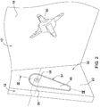
- Fig. 2 If the vehicle tank 12 is penetrated by a through opening 30 in the area of the tank wall 18, which cooperates with a reinforcement device 32 in a manner to be described below.
- the reinforcing devices 32 described here flank a tank wall of the vehicle tank 12 that is to be reinforced in order to protect the reinforced tank wall from bulges or deformations or to limit such bulges or deformations to a maximum permissible level.
- the material of the reinforcement e.g. sheet steel
- the material of the tank wall to be reinforced e.g. plastic
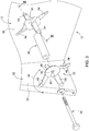
- Fig. 3 shows a first embodiment of the reinforcement device 32. It contains several components in the manner of a kit, namely at least one reinforcement shield 34, a spacer sleeve 36, a tensioning element in the form of a tensioning screw 38, a washer 40 and a screw nut 42, which in the assembly position of the reinforcement device 32 interacts with an external thread 44 of the tensioning screw 38 ( Fig. 4 ).
- the reinforcement shield 34 according to Fig. 3 has a total of four reinforcement struts 46, which are arranged uniformly in a circumferential direction 48 of the reinforcement shield 34.
- the circumferential direction 48 runs at right angles to an axial direction 50 and a flank direction 52 of the reinforcement device 32 ( Fig. 4 ).
- the flank direction 52 runs at right angles to the axial direction 50 and can therefore also be referred to as a radial direction.
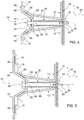
- the reinforcement struts 46 lie in channel-like wall recesses 54 of the tank wall 18 and flank individual sections of the tank wall 18 along the flank direction 52.
- the reinforcement struts 46 lie directly against the tank wall 18 and cause reinforcement in the axial direction 50, ie the reinforcement struts 34 prevent the tank wall 18 from bulging in the axial direction 50.
- a transition section 56 of the individual reinforcement struts 46 that runs differently from the flank direction 52 also flanks a further section of the tank wall 18, so that the reinforcement struts 46 also reinforce the vehicle tank 12 in the flank direction 52 or cause radial direction.
- the transition section 56 connects the respective reinforcement strut 46 with a common shield bearing 58, which serves as a component of the reinforcement shield 34 for its storage in the assembly position.
- the shield bearing 58 is penetrated by a bearing opening 60 in the axial direction 50 in order to receive the clamping screw 38 in the assembly position.
- the reinforcement struts 46 are connected in one piece to the common shield bearing 58.
- the shield bearing 58 In the mounting position according to Fig. 4 the shield bearing 58 is fixed axially secured in the axial direction 50 by means of the clamping screw 38, namely axially clamped between the screw head of the clamping screw 38 and the spacer sleeve 36.
- the external thread 44 of the tensioning screw 38 passes through a mounting opening 62 of the support structure 14 and interacts with the screw nut 42 in the usual manner.
- the axially secured fixing of the shield bearing 58 simultaneously effects an axially secured bearing of the reinforcing struts 46 and thus of the entire armoring shield 34.
- the reinforcement device 32 according to Fig. 5 differs from the embodiment according to Fig. 4 essentially in that the reinforcement shield 34 in the assembly position only rests directly on the tank wall 18 with a radially outer portion of its reinforcement struts 46, while radially inner portions of the reinforcement struts 46 flank the tank wall 18 at an axial distance.
- the shield bearing 58 is in turn connected in one piece to the reinforcing struts 46.
- the reinforcement shield 34 can have a different number of reinforcement struts 46 depending on the application.
- the reinforcement struts 46 can have different geometric cross-sectional shapes - even within a single reinforcement shield 34.
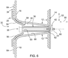
- the reinforcement struts 46 of a reinforcement shield 34 can be replaced by a washer-like reinforcement 64 ( Fig. 6 ), which is made available either in one piece with the shield bearing 58 or as a separate component. In the latter case it bears preferably the shield bearing 58, the transition section 56.
- the shield bearing 58 is preferably designed to be rotationally symmetrical with respect to a central longitudinal axis 66 of the reinforcement device 32.
- the transition component 56 is an integral part of the shield bearing 58, as in FIG Fig. 6 shown.
- the annular disk-like reinforcement 64 is supported in the assembly position on the shield bearing 58, in that the shield bearing 58 or the transition section 56 clamps the reinforcement 64 axially between itself and the tank wall 18.
- the reinforcement 64 is in direct contact with the tank wall 18.
- the inside and / or outside diameter of the reinforcement 64 can be dimensioned differently with respect to the central longitudinal axis 66.
- the reinforcement shield 34 has four individual reinforcement struts 46, which in the assembly position along the circumferential direction 48 analogously to Fig. 3 in turn arranged evenly distributed and each assigned to a wall recess 54.
- each reinforcement strut 46 is integrally connected to a shield bearing 58.
- Each shield bearing 58 is penetrated by a bearing opening 60.
- Fig. 9 an embodiment of the reinforcement device 32 is shown, which in contrast to the variants according to FIG 4 to 6 and Fig. 8 is not fixed to the support structure 14, but to the vehicle tank 12 itself.
- This is useful in the case of tank walls which, due to their position relative to the support structure 14 of the vehicle 10, do not allow the reinforcement device to be fixed to the support structure 14, or only allow it to be fixed in a very laborious manner this is the case, for example, with tank wall 22 ( Fig. 2 ).
- the reinforcement device 32 is shown in FIG Fig. 9 therefore releasably connected to an outer wall 68 of the vehicle tank 12. This can be done in different ways, as explained below.
- a reinforcement strut 46 is provided as a reinforcement shield 34, which cooperates with a separate shield bearing 58 and is axially penetrated by this.
- the shield bearing 58 has a T-shaped cross-section and acts as an adapter for mounting different reinforcement struts 46, in that its outer diameter can be dimensioned differently in the radial direction 52 with the same bearing opening 60 in order to be able to mount correspondingly differently dimensioned reinforcement struts 46.
- the reinforcing strut 46 can also deviate from a strut-like cross-sectional shape as required.
- the shield bearing 58 is shown in the assembly position Fig. 9 axially secured by means of the screwed clamping screw 38.
- the reinforcement strut 46 is clamped axially between the shield bearing 58 and the tank wall 18 to be reinforced, so that the reinforcement shield 34 having the reinforcement strut 46 is supported and fixed in an axially secured manner.
- the reinforcement strut 46 flanks the tank wall 18 to be reinforced in that it rests directly there.
- the clamping screw 38 cooperates with suitable fixing means on the side of the through opening 30 of the vehicle tank 12 axially facing away from the reinforcement shield 34.
- a threaded insert 70 is provided with an internal thread which is cast into the through opening 30 is ( Fig. 9 ) or is hammered into the through opening 30 like a pin or dowel ( Fig. 10 ).
- the outer wall 68 itself forms the fixing means cooperating with the clamping screw 38.
- the clamping screw 38 has a self-tapping thread 72 that cuts into the outer wall 68.
- loosening the screw connection by means of the tensioning screw 38 also causes the axial securing of the shield bearing 58 and the armoring shield 34 to be loosened with respect to the vehicle tank 12.
Landscapes
- Engineering & Computer Science (AREA)
- Life Sciences & Earth Sciences (AREA)
- Sustainable Development (AREA)
- Sustainable Energy (AREA)
- Chemical & Material Sciences (AREA)
- Combustion & Propulsion (AREA)
- Transportation (AREA)
- Mechanical Engineering (AREA)
- Cooling, Air Intake And Gas Exhaust, And Fuel Tank Arrangements In Propulsion Units (AREA)
Description
- Die Erfindung betrifft eine Armierung einer Tankwand eines Fahrzeugtanks. Weiterhin betrifft die Erfindung ein Fahrzeug mit einem Fahrzeugtank und einer Armierung einer Tankwand des Fahrzeugtanks.
- Bei landwirtschaftlichen Fahrzeugen ist es bekannt, dass deren Treibstofftanks abhängig von bestimmten Innendruckverhältnissen, hydrostatischem Druck oder Temperatureinflüssen an den Tankwänden relativ großen Kräften ausgesetzt sein können. Um etwaige Verformungen der oftmals aus Kunststoff bestehenden Tankwände durch diese Kräfte zu vermeiden, kann beispielsweise die Dicke der Tankwände größer dimensioniert werden oder die konstruktive Ausgestaltung der Tankwände kann Wandrippen als Armierung aufweisen, welche die Tankwände zusätzlich versteifen.
- Die
EP 2 537 696 A1 offenbart eine Armierung für eine Tankwand eines Fahrzeugtanks, mit mindestens einem Armierungsschild zur Flankierung der Tankwand. - Der vorliegenden Erfindung liegt die Aufgabe zugrunde, eine verbesserte Armierung für Tankwände eines Fahrzeugtanks anzugeben.
- Diese Aufgabe wird gemäß den Merkmalen der Patentansprüche 1 und 10 gelöst.
- Erfindungsgemäß ist eine Vorrichtung zur Armierung einer Tankwand eines Fahrzeugtanks vorgesehen, welche mindestens einen Armierungsschild zur Flankierung der Tankwand und ein Schildlager zur Lagerung des Armierungsschildes aufweist. Dabei ist das Schildlager in einer Axialrichtung an einem Spannelement einer Spanneinrichtung axialgesichert fixiert, so dass auch der Armierungsschild aufgrund seiner Lagerung an dem Schildlager vor unerwünschten Bewegungen entlang der Axialrichtung gesichert ist. Außerdem erstreckt sich der Armierungsschild zumindest teilweise in einer Flankenrichtung, welche quer zur Axialrichtung verläuft. Auf diese Weise flankiert der Armierungsschild eine Tankwand entlang der Flankenrichtung und wirkt als Armierung etwaigen unerwünschten Verformungen bzw. Deformationen dieser flankierten Tankwand entgegen.
- Insbesondere verläuft die Flankenrichtung rechtwinklig zur Axialrichtung der Armierungsvorrichtung, d.h. in einer Radialrichtung der Armierungsvorrichtung.
- Je nach Ausgestaltung der Vorrichtung kann der Armierungsschild die betroffene Tankwand entweder mit Abstand flankieren oder der Armierungsschild liegt an der jeweiligen Tankwand unmittelbar an. Die Auswahl einer dieser beiden Ausgestaltungen hängt vor allem davon ab, ob eine gewisse Verformung bzw. Ausbeulung der Tankwand zugelassen werden soll oder nicht. Vorteilhaft sind das Schildlager und der Armierungsschild derart dimensioniert, dass die Tankwand nach Erreichen einer ersten Verformung unmittelbar an dem Armierungsschild anliegt, so dass eine zusätzliche Verformung verhindert wird.
- Die Lagerung des Armierungsschildes an dem Schildlager kann z.B. durch eine einstückige Verbindung zwischen beiden Bauteilen realisiert sein. Alternativ sind der Armierungsschild und das Schildlager separate Bauteile. Sie können fest miteinander verbunden sein. In einer weiteren Ausführung kann das in einer Montageposition der Vorrichtung axialgesicherte Schildlager dazu genutzt werden, den Armierungsschild automatisch relativ zu einer Tankwand zu fixieren, z.B. zwischen dem Schildlager und der Tankwand einzuklemmen.
- Durch den Einsatz der Armierungsvorrichtung können gezielt diejenigen Abschnitte von Tankwänden armiert werden, die bei bestimmten physikalischen Randbedingungen oder Umgebungsbedingungen am ehesten eine Tendenz zu Verformungen oder Ausbeulungen zeigen. Hierdurch wird eine stärkere Dimensionierung der gesamten Tankwandungen des Fahrzeugtanks vermieden. Auch kostenaufwändigere konstruktive Ausgestaltungen der Tankwandungen mit integrierten Versteifungsrippen oder anderen Konstruktionsmaßnahmen an den Tankwandungen sind überflüssig.
- Mit der Armierungsvorrichtung wird eine herstellungstechnisch einfache separate Vorrichtung bereitgestellt, um Verformungen bzw. Ausbeulungen zu vermeiden oder zumindest derart zu begrenzen, dass bestimmte Mindestabstände zu anderen, insbesondere rotierenden, Komponenten (z.B. Reifen von Fahrzeugrädern) eines Fahrzeugs eingehalten werden. Hierdurch kann bei der Ausgestaltung des Fahrzeugtanks selbst auf entsprechende Sicherheitsmaßnahmen verzichtet werden.
- In einer bevorzugten Ausführungsform ist die Axialsicherung des Schildlagers und somit auch des Armierungsschildes lösbar ausgebildet. Dies kann mittels einer geeigneten Ausgestaltung der Spanneinrichtung (z.B. eines Schraubmechanismus) erzielt werden. Die lösbare Axialsicherung unterstützt einen flexiblen Einsatz der Armierungsvorrichtung. Im Falle einer irreversiblen Beschädigung oder Defektes des Fahrzeugtanks kann die Armierungsvorrichtung kostensparend weiterverwendet werden. Weiterhin können nach dem Lösen der Axialsicherung einzelne Komponenten der Armierungsvorrichtung bedarfsweise ausgetauscht bzw. ersetzt werden, während die übrigen Komponenten weiterverwendet werden können.
- Vorzugsweise ist der Armierungsschild zumindest abschnittsweise bezüglich einer Ebene des Schildlagers axial versetzt angeordnet. Hierdurch lässt sich die Armierungsvorrichtung an unterschiedliche geometrische Querschnitte von Tankwänden gut anpassen.
- Insbesondere weist der Armierungsschild einen Übergangsabschnitt für eine feste Verbindung (z.B. einstückig) mit dem Schildlager auf. Im Falle von axial versetzten Ebenen zwischen dem Armierungsschild und dem Schildlager kann ein derartiger Übergangsabschnitt neben seiner Verbindungsfunktion zwischen Armierungsschild und Schildlager dazu verwendet werden, an quer zur Flankenrichtung verlaufenden Wandabschnitten des Fahrzeugtanks eine Armierungswirkung zu erzielen.
- Der Armierungsschild liegt vorzugsweise im Wesentlichen in einer Ebene (oder mehreren Ebenen) ein, welche parallel zur Flankenrichtung angeordnet ist bzw. sind. Hierbei kann der Armierungsschild unterschiedlich ausgestaltet sein, z.B. als eine rotationssymmetrische Scheibe. Erfindungsgemäß weist der Armierungsschild in einer quer zur Axialrichtung und quer zur Flankenrichtung verlaufenden Umfangsrichtung einen oder mehrere strebenartige Armierungsabschnitte auf. Mit geringem Materialeinsatz für den Armierungsschild kann somit eine verhältnismäßig große Wandfläche des Fahrzeugtanks wirksam armiert werden.
- Vorteilhaft sind im Falle mehrerer Armierungsabschnitte bzw. Armierungsstreben mindestens zwei Armierungsstreben in Axialrichtung versetzt angeordnet. Hierdurch ist die Armierungsvorrichtung flexibel an komplexe Querschnittsverläufe einer Tankwand und auch an geometrisch unterschiedliche Typen von Fahrzeugtanks anpassbar.
- Abhängig von der jeweiligen Tankwand werden eine Armierungsstrebe oder vorzugsweise mehrere einzelne Armierungsstreben eingesetzt, was den baukastenartigen, modularen Charakter der Armierungsvorrichtung und somit deren flexiblen Einsatz unterstützt.
- Die Armierungsstreben eines Armierungsschildes können identisch oder bei Bedarf unterschiedlich ausgestaltet sein, um gegebenenfalls eine Anpassung des Armierungsschildes an unterschiedliche Oberflächen- und Querschnittsverläufe einer zu armierenden Tankwand zu erreichen.
- In einer bevorzugten Ausführungsform ist das Schildlager in Axialrichtung von einer Lageröffnung durchsetzt, um eine einfache Montage der Armierungsvorrichtung zu unterstützen. Beispielsweise durchsetzt in Montageposition das Spannelement (z.B. eine Spannschraube) die Lageröffnung in Axialrichtung, um eine montagefreundliche Einspannung des Schildlagers und somit auch des Armierungsschildes zu erreichen.
- Zur Unterstützung der Armierungswirkung ist die Steifigkeit und/oder Härte des Materials des Armierungsschildes größer als die entsprechende Materialeigenschaft der zu armierenden Tankwand. Mit anderen Worten sind die Materialeigenschaften des Armierungsschildes im Vergleich zur Tankwand derart unterschiedlich, dass der Armierungsschild bei gleichen physikalischen Bedingungen gar keine Verformungen bzw. Deformationen oder zumindest geringere Verformungen bzw. Deformationen aufweist. Beispielsweise wird für den Armierungsschild ein Stahlblech verwendet, während die Tankwand aus einem Kunststoff besteht.
- Vorzugsweise besteht der Armierungsschild und/oder das Schildlager aus einem metallischen Blech, insbesondere Stahlblech. Bei einer entsprechend dimensionierten Blechstärke kann der Armierungsschild ohne zusätzliche Maßnahmen eine ausreichend starre Barriere gegen Verformungen der flankierten Tankwand bilden. Fertigungstechnisch einfach lässt sich der Armierungsschild und/oder das Schildlager als tiefgezogenes Blechteil herstellen. Hierdurch kann die Armierungs-Vorrichtung kostengünstig an die jeweilige geometrisch-konstruktive Ausgestaltung der zu armierenden Tankwände angepasst werden.
- Wie bereits erwähnt, wird die Armierung bei einem Fahrzeugtank bzw. Treibstoffbehälter für Fahrzeuge, insbesondere landwirtschaftliche Fahrzeuge, eingesetzt.
- Vorzugsweise weist der Fahrzeugtank eine von seiner Außenwandung begrenzte axiale Durchgangsöffnung auf, welche die Spanneinrichtung zumindest abschnittsweise aufnehmen kann und hierdurch als Montagehilfe für die Armierungsvorrichtung dient. Sollte diese Durchgangsöffnung für die Spanneinrichtung bei spezifischen Anwendungsfällen nicht benötigt werden, kann sie in einer weiteren Funktion dennoch als Montagehilfe für eine stabile Befestigung des Fahrzeugtanks an einer Tragstruktur des Fahrzeugs, z.B. eines Chassis, verwendet werden.
- In einer bevorzugten Ausführungsform durchsetzt das Spannelement (z.B. eine Spannschraube) der Spanneinrichtung die Durchgangsöffnung des Fahrzeugtanks und ist außerdem an einer Tragstruktur des Fahrzeugs fixiert (z.B. verschraubt). Auf diese Weise kann mit einfachen mechanischen Mitteln eine Befestigung der Armierungsvorrichtung an der Tragstruktur und gleichzeitig die gewünschte stabile Armierung des Fahrzeugtanks erzielt werden.
- Alternativ ist eine stabile Befestigung der Armierungsvorrichtung ausschließlich an den Tankwandungen möglich, wenn an der Tragstruktur des Fahrzeugs keine geeignete Befestigungsstelle vorhanden ist. Zu diesem Zweck ist vorzugsweise vorgesehen, dass das Spannelement die Durchgangsöffnung des Fahrzeugtanks durchsetzt und im Bereich einer axial gegenüberliegenden Außenwandung des Fahrzeugtanks fixiert ist.
- Eine Fixierung des Spannelements an dem Fahrzeugtank kann auf unterschiedliche Weise erfolgen. Beispielweise wirkt das Spannelement an der dem Armierungsschild axial abgewandten Seite der Durchgangsöffnung des Fahrzeugtanks mit geeigneten Fixiermitteln zusammen, um eine stabile Fixierung des Spannelements und somit eine stabile Lagerung des Armierungsschildes in Montageposition der Armierungsvorrichtung zu erreichen. Diese Fixiermittel sind z.B. als ein an der Durchgangsöffnung befestigter Gewindeeinsatz mit einem Innengewinde ausgestaltet, welches mit einem Außengewinde des Spannelements zusammenwirkt. Alternativ können Fixiermittel vorgesehen sein, welche außerhalb der Montageposition der Spanneinrichtung lose zur Verfügung stehen und erst in Montageposition eine feste Relativlage zum Fahrzeugtank einnehmen. Diese Fixiermittel können z.B. als Schraubmuttern, Unterlegscheiben und auch als ein weiterer Armierungsschild ausgebildet sein.
- Die erfindungsgemäße Armierung wird im Folgenden anhand der beigefügten Zeichnungen näher erläutert. Dabei sind hinsichtlich ihrer Funktion übereinstimmende bzw. vergleichbare Bauteile mit denselben Bezugszeichen gekennzeichnet. Übereinstimmende bzw. vergleichbare Bauteile können in den Zeichnungen maßstäblich unterschiedlich dargestellt sein. Es zeigen:
- Fig. 1
- eine perspektivische Ansicht eines an einem Fahrzeug befestigten Fahrzeugtanks,
- Fig. 2
- eine perspektivische Ansicht des Fahrzeugtanks gemäß
Fig. 1 , mit dargestellten Durchgangsöffnungen, - Fig. 3
- eine perspektivische Detaildarstellung des Fahrzeugtanks gemäß
Fig. 2 und einer Armierung in Explosionsdarstellung, - Fig. 4
- eine geschnittene Seitenansicht der Armierung gemäß
Fig. 3 in Montageposition entsprechend Schnittlinie IV-IV inFig. 3 , - Fig. 5
- eine geschnittene Seitenansicht der Armierung in Montageposition in einer weiteren Ausführungsform,
- Fig. 6
- eine geschnittene Seitenansicht der Armierung in Montageposition in einer weiteren Ausführungsform,
- Fig. 7
- die perspektivische Darstellung des Fahrzeugtanks gemäß
Fig. 3 und einer Armierung in Explosionsdarstellung in einer weiteren Ausführungsform, - Fig. 8
- eine geschnittene Seitenansicht der Armierung gemäß
Fig. 7 in Montageposition entsprechend Schnittlinie VIII-VIII inFig. 7 , - Fig. 9
- eine geschnittene Seitenansicht der Armierung in Montageposition entsprechend Schnittlinie IX-IX in
Fig. 2 , mit einer an einer Außenwandung des Fahrzeugtanks fixierten Spanneinrichtung, - Fig. 10
- eine vergrößerte Darstellung des Detailbereichs X in
Fig. 9 , in einer weiteren Ausführungsform, - Fig. 11
- der Detailbereich X in
Fig. 9 , in einer weiteren Ausführungsform, - Fig. 12
- der Detailbereich X in
Fig. 9 , in einer weiteren Ausführungsform, und - Fig. 13
- der Detailbereich X in
Fig. 9 , in einer weiteren Ausführungsform. -
Fig. 1 zeigt ausschnittsweise ein landwirtschaftliches Fahrzeug 10 (z.B. einen Traktor), nämlich dessen Fahrzeugtank 12, der einen plattenartigen Abschnitt einer Tragstruktur 14 (z.B. eines Chassis) des Fahrzeugs 10 flankiert oder unmittelbar an diesem Abschnitt befestigt ist. Der Fahrzeugtank 12 dient der Lagerung von Treibstoff zum Antrieb des Fahrzeugs 10. Die außenliegenden Tankwände des Fahrzeugtanks 12 sollen vor Ausbeulungen bzw. Verformungen derart geschützt sein, dass andere Bauteile des Fahrzeugs 10 mit den Tankwänden des Fahrzeugtanks nicht in Berührung kommen. Beispielsweise muss eine sich in Längsrichtung 16 bzw. Fahrtrichtung des Fahrzeugs 10 erstreckende Tankwand 18 und eine sich in Querrichtung 20 des Fahrzeugs 10 erstreckende Tankwand 22 vor einem Kontakt mit einem rotierenden (hier jedoch nicht dargestellten) Reifen einer Hinterachse 24 des Fahrzeugs 10 geschützt werden. Der Reifen rotiert dabei um eine Rotationsachse 26 der Hinterachse 24. Entsprechend muss z.B. auch eine der Tankwand 22 in Längsrichtung 16 gegenüberliegende Tankwand 28 ausreichend Abstand zu anderen Bauteilen des Fahrzeugs 10 haben. - Gemäß
Fig. 2 ist der Fahrzeugtank 12 im Bereich der Tankwand 18 von einer Durchgangsöffnung 30 durchsetzt, welche in noch zu beschreibender Weise mit einer Armierungsvorrichtung 32 zusammenwirkt. Prinzipiell flankieren die hier beschriebenen Armierungsvorrichtungen 32 eine zu armierende Tankwand des Fahrzeugtanks 12, um die armierte Tankwand vor Ausbeulungen bzw. Verformungen zu schützen oder derartige Ausbeulungen bzw. Verformungen auf ein zulässiges Höchstmaß zu begrenzen. Dabei weist der Werkstoff der Armierung (z.B. Stahlblech) eine größere Steifigkeit auf als der Werkstoff der zu armierenden Tankwand (z. B. Kunststoff). -
Fig. 3 zeigt eine erste Ausführungsform der Armierungsvorrichtung 32. Sie enthält nach Art eines Bausatzes mehrere Bauteile, nämlich zumindest einen Armierungsschild 34, eine Abstandshülse 36, ein Spannelement in Form einer Spannschraube 38, eine Unterlegscheibe 40 und eine Schraubmutter 42, welche in Montageposition der Armierungsvorrichtung 32 mit einem Außengewinde 44 der Spannschraube 38 zusammenwirkt (Fig. 4 ). Der Armierungsschild 34 gemäßFig. 3 weist insgesamt vier Armierungsstreben 46 auf, welche gleichmäßig in einer Umfangsrichtung 48 des Armierungsschildes 34 angeordnet sind. Die Umfangsrichtung 48 verläuft rechtwinklig zu einer Axialrichtung 50 und einer Flankenrichtung 52 der Armierungsvorrichtung 32 (Fig. 4 ). Die Flankenrichtung 52 verläuft rechtwinklig zur Axialrichtung 50 und kann deshalb auch als eine Radialrichtung bezeichnet werden. - In Montageposition der Armierungsvorrichtung 32 gemäß
Fig. 4 liegen erfindungsgemäß zumindest die radialen Freienden der Armierungsstreben 46 in kanalartigen Wandausnehmungen 54 der Tankwand 18 ein und flankieren dabei einzelne Abschnitte der Tankwand 18 entlang der Flankenrichtung 52. Dabei liegen die Armierungsstreben 46 an der Tankwand 18 unmittelbar an und bewirken eine Armierung in Axialrichtung 50, d.h. die Armierungsstreben 34 verhindern ein Ausbeulen der Tankwand 18 in Axialrichtung 50. Darüber hinaus flankiert auch ein abweichend von der Flankenrichtung 52 verlaufender Übergangsabschnitt 56 der einzelnen Armierungsstreben 46 einen weiteren Abschnitt der Tankwand 18, so dass die Armierungsstreben 46 auch eine Armierung des Fahrzeugtanks 12 in Flankenrichtung 52 bzw. Radialrichtung bewirken. Der Übergangsabschnitt 56 verbindet die jeweilige Armierungsstrebe 46 mit einem gemeinsamen Schildlager 58, welches als Bestandteil des Armierungsschildes 34 seiner Lagerung in Montageposition dient. Das Schildlager 58 ist in Axialrichtung 50 von einer Lageröffnung 60 durchsetzt, um in Montageposition die Spannschraube 38 aufzunehmen. Die Armierungsstreben 46 sind mit dem gemeinsamen Schildlager 58 einstückig verbunden. In Montageposition gemäßFig. 4 ist das Schildlager 58 in Axialrichtung 50 mittels der Spannschraube 38 axialgesichert fixiert, nämlich zwischen dem Schraubenkopf der Spannschraube 38 und der Abstandshülse 36 axial eingespannt. Dabei durchsetzt das Außengewinde 44 der Spannschraube 38 eine Montageöffnung 62 der Tragstruktur 14 und wirkt in üblicher Weise mit der Schraubmutter 42 zusammen. Die axialgesicherte Fixierung des Schildlagers 58 bewirkt gleichzeitig eine axialgesicherte Lagerung der Armierungsstreben 46 und somit des gesamten Armierungsschildes 34. - Die Armierungsvorrichtung 32 gemäß
Fig. 5 unterscheidet sich von der Ausführungsform gemäßFig. 4 im Wesentlichen dadurch, dass der Armierungsschild 34 in Montageposition nur mit einem radial äußeren Abschnitt seiner Armierungsstreben 46 unmittelbar an der Tankwand 18 anliegt, während radial innere Abschnitte der Armierungsstreben 46 die Tankwand 18 mit axialem Abstand flankieren. Das Schildlager 58 ist wiederum einstückig mit den Armierungsstreben 46 verbunden. - Ganz allgemein kann der Armierungsschild 34 je nach Anwendungsfall eine unterschiedliche Anzahl von Armierungsstreben 46 aufweisen. Die Armierungsstreben 46 können - auch innerhalb eines einzigen Armierungsschildes 34 - unterschiedliche geometrische Querschnittsformen haben. In weiteren Ausführungsformen können die Armierungsstreben 46 eines Armierungsschildes 34 durch eine ringscheibenartige Armierung 64 ersetzt sein (
Fig. 6 ), welche entweder einstückig mit dem Schildlager 58 oder als separates Bauteil zur Verfügung gestellt wird. In letzterem Fall trägt vorzugsweise das Schildlager 58 den Übergangsabschnitt 56. Das Schildlager 58 ist vorzugsweise rotationssymmetrisch bezüglich einer Mittellängsachse 66 der Armierungsvorrichtung 32 ausgebildet. - Insbesondere ist der Übergangsbestandteil 56 einstückiger Bestandteil des Schildlagers 58, wie in
Fig. 6 dargestellt. GemäßFig. 6 lagert die ringscheibenartige Armierung 64 in Montageposition an dem Schildlager 58, indem das Schildlager 58 bzw. der Übergangsabschnitt 56 die Armierung 64 axial zwischen sich und der Tankwand 18 einspannt. Dabei liegt die Armierung 64 unmittelbar an der Tankwand 18 an. Je nach Anwendungsfall kann der Innen- und/oder Außendurchmesser der Armierung 64 bezüglich der Mittellängsachse 66 unterschiedlich dimensioniert sein. - Gemäß
Fig. 7 weist der Armierungsschild 34 vier einzelne Armierungsstreben 46 auf, welche in Montageposition entlang der Umfangsrichtung 48 analog zuFig. 3 wiederum gleichmäßig verteilt angeordnet und jeweils einer Wandausnehmung 54 zugeordnet sind. Bei dieser Variante ist jede Armierungsstrebe 46 mit einem Schildlager 58 einstückig verbunden. Jedes Schildlager 58 ist von einer Lageröffnung 60 durchsetzt. - In
Fig. 9 ist eine Ausführungsform der Armierungsvorrichtung 32 dargestellt, welche im Gegensatz zu den Varianten gemäßFig. 4 bis Fig. 6 undFig. 8 nicht an der Tragstruktur 14, sondern an dem Fahrzeugtank 12 selbst fixiert ist. Dies ist bei Tankwänden sinnvoll, welche aufgrund ihrer Relativlage zur Tragstruktur 14 des Fahrzeugs 10 eine Fixierung der Armierungsvorrichtung an der Tragstruktur 14 nicht oder nur sehr umständlich zulassen, wie dies z.B. bei der Tankwand 22 der Fall ist (Fig. 2 ). In Montageposition ist die Armierungsvorrichtung 32 gemäßFig. 9 deshalb mit einer Außenwandung 68 des Fahrzeugtanks 12 lösbar verbunden. Dies kann auf unterschiedliche Weise erfolgen, wie nachfolgend erläutert. Bei allen diesen Varianten ist als Armierungsschild 34 eine Armierungsstrebe 46 vorgesehen, welche mit einem separaten Schildlager 58 zusammenwirkt und von diesem axial durchsetzt ist. Das Schildlager 58 hat einen T-förmigen Querschnitt und wirkt als Adapter zur Lagerung unterschiedlicher Armierungsstreben 46, indem dessen Außendurchmesser in Radialrichtung 52 bei gleichbleibender Lageröffnung 60 unterschiedlich dimensioniert werden können, um entsprechend unterschiedlich dimensionierte Armierungsstreben 46 lagern zu können. Die Armierungsstrebe 46 kann je nach Bedarf auch von einer strebenartigen Querschnittsform abweichen. Das Schildlager 58 ist in Montageposition gemäßFig. 9 mittels der verschraubten Spannschraube 38 axialgesichert fixiert. Gleichzeitig ist die Armierungsstrebe 46 axial zwischen dem Schildlager 58 und der zu armierenden Tankwand 18 eingespannt, so dass der die Armierungsstrebe 46 aufweisende Armierungsschild 34 axialgesichert gelagert und fixiert ist. Die Armierungsstrebe 46 flankiert die zu armierende Tankwand 18, indem sie dort unmittelbar anliegt. - Zur Fixierung der Armierungsvorrichtung 32 an der Außenwandung 68 des Fahrzeugtanks 12 wirkt die Spannschraube 38 an der dem Armierungsschild 34 axial abgewandten Seite der Durchgangsöffnung 30 des Fahrzeugtanks 12 mit geeigneten Fixiermitteln zusammen. Beispielsweise ist ein Gewindeeinsatz 70 mit einem Innengewinde vorgesehen, welcher in die Durchgangsöffnung 30 eingegossen ist (
Fig. 9 ) oder in die Durchgangsöffnung 30 nach Art eines Dorns bzw. Dübels eingeschlagen ist (Fig. 10 ). - In der Ausführungsform gemäß
Fig. 11 bildet die Außenwandung 68 selbst die mit der Spannschraube 38 zusammenwirkenden Fixiermittel. Hierbei trägt die Spannschraube 38 an ihrem dargestellten Axialende ein selbstschneidendes Gewinde 72, das sich in die Außenwandung 68 einschneidet. - In
Fig. 12 ist die Spannschraube 38 und somit die Armierungsvorrichtung 32 an der Außenwandung 68 fixiert, indem die Schraubmutter 42 unter Zwischenlage einer ringartigen Beilagscheibe 74 mit dem Außengewinde 44 verschraubt wird. InFig. 13 ist die Beilagscheibe 74 durch eine weitere Armierungsstrebe 46 ersetzt, welche auf der dem Schildlager 58 gemäßFig. 9 axial gegenüberliegenden Seite der Durchgangsöffnung 30 eine Flankierung und Armierung eines Abschnitts der Außenwandung 68 bewirken kann. - Bei allen dargestellten Ausführungsformen bewirkt ein Lösen der Schraubverbindung mittels der Spannschraube 38 auch ein Lösen der Axialsicherung des Schildlagers 58 und des Armierungsschildes 34 bezüglich des Fahrzeugtanks 12.
Claims (14)
- Armierung (32) für eine Tankwand (18, 22) eines Fahrzeugtanks (12), mit mindestens einem Armierungsschild (34) zur Flankierung der Tankwand (18, 22) und mit einem Schildlager (58) zur Lagerung des Armierungsschildes (34), wobei- das Schildlager (58) in einer Axialrichtung (50) an einem Spannelement (38) axialgesichert fixiert ist, und- der Armierungsschild (34) sich zumindest abschnittsweise in einer quer zur Axialrichtung (50) verlaufenden Flankenrichtung (52) erstreckt, dadurch gekennzeichnet, dass der Armierungsschild (34) in einer quer zur Axialrichtung (50) und quer zur Flankenrichtung (52) verlaufenden Umfangsrichtung mindestens eine Armierungsstrebe (46) aufweist, wobei in einer Montageposition der Armierung (32) zumindest ein radiales Freiende der mindestens einen Armierungsstrebe (46) in einer kanalartigen Wandausnehmung (54) der Tankwand (18, 22) einlegbar ist und dabei einzelne Abschnitte der Tank-wand (18, 22) entlang der Flankenrichtung (52) flankiert.
- Armierung nach Anspruch 1, dadurch gekennzeichnet, dass die Axialsicherung des Schildlagers (58) lösbar ist.
- Armierung nach Anspruch 1 oder 2, dadurch gekennzeichnet, dass der Armierungsschild (34) zumindest abschnittsweise relativ zum Schildlager (58) axial versetzt angeordnet ist.
- Armierung nach einem der vorhergehenden Ansprüche, dadurch gekennzeichnet, dass der Armierungsschild (34) mittels eines Übergangsabschnittes (56) mit dem Schildlager (58) fest verbunden ist.
- Armierung nach Anspruch 1, dadurch gekennzeichnet, dass mindestens zwei Armierungsstreben (46) in Axialrichtung (50) versetzt angeordnet sind.
- Armierung nach einem der vorhergehenden Ansprüche, dadurch gekennzeichnet, dass das Schildlager (58) in Axialrichtung (50) von einer Lageröffnung (60) durchsetzt ist.
- Armierung nach Anspruch 6, dadurch gekennzeichnet, dass in Montageposition des Armierungsschildes (34) das Spannelement (38) die Lageröffnung (60) des Schildlagers (58) axial durchsetzt.
- Armierung nach einem der vorhergehenden Ansprüche, dadurch gekennzeichnet, dass das Spannelement (38) ein Schraubgewinde (44) aufweist zur axialgesicherten Fixierung des Schildlagers (58).
- Armierung nach einem der vorhergehenden Ansprüche, dadurch gekennzeichnet, dass der Armierungsschild (34) und/oder das Schildlager (58) aus metallischem Blech bestehen.
- Fahrzeug (10) mit einem Fahrzeugtank (12) und einer Armierung (32) für eine Tankwand (18, 22) des Fahrzeugtanks (12) nach Anspruch 1, wobei die Tankwand (18, 22) eine kanalartige Wandausnehmung (54) aufweist und wobei in der Montageposition der Armierung (32) zumindest ein radiales Freiende der mindestens einen Armierungsstrebe (46) in der kanalartigen Wandausnehmung (54) der Tankwand (18, 22) einliegt und dabei einzelne Abschnitte der Tankwand (18, 22) entlang der Flankenrichtung (52) flankiert.
- Fahrzeug nach Anspruch 10, dadurch gekennzeichnet, dass der Fahrzeugtank (12) eine von seiner Außenwandung (68) begrenzte axiale Durchgangsöffnung (30) aufweist zur zumindest abschnittsweisen Aufnahme des Spannelements (38).
- Fahrzeug nach Anspruch 11, dadurch gekennzeichnet, dass das Spannelement (38) die Durchgangsöffnung (30) des Fahrzeugtanks (12) durchsetzt und an einer Tragstruktur (14) des Fahrzeugs (10) fixiert ist.
- Fahrzeug nach Anspruch 11, dadurch gekennzeichnet, dass das Spannelement (38) die Durchgangsöffnung (30) des Fahrzeugtanks (12) durchsetzt und an der Außenwandung (68) des Fahrzeugtanks (12) fixiert ist.
- Fahrzeug nach Anspruch 12 oder 13, dadurch gekennzeichnet, dass das Spannelement (38) an der dem Armierungsschild (34) axial abgewandten Seite der Durchgangsöffnung (30) des Fahrzeugtanks (12) mit Fixiermitteln (42, 46, 70, 72, 74) zusammenwirkt zur Fixierung des Spannelements (38).
Applications Claiming Priority (1)
| Application Number | Priority Date | Filing Date | Title |
|---|---|---|---|
| DE102016213103.6A DE102016213103A1 (de) | 2016-07-18 | 2016-07-18 | Fahrzeug mit einem Fahrzeugtank und Armierung für einen Fahrzeugtank |
Publications (2)
| Publication Number | Publication Date |
|---|---|
| EP3272566A1 EP3272566A1 (de) | 2018-01-24 |
| EP3272566B1 true EP3272566B1 (de) | 2020-08-12 |
Family
ID=59366238
Family Applications (1)
| Application Number | Title | Priority Date | Filing Date |
|---|---|---|---|
| EP17181220.9A Active EP3272566B1 (de) | 2016-07-18 | 2017-07-13 | Fahrzeug mit einem fahrzeugtank und armierung für einen fahrzeugtank |
Country Status (3)
| Country | Link |
|---|---|
| US (1) | US10525825B2 (de) |
| EP (1) | EP3272566B1 (de) |
| DE (1) | DE102016213103A1 (de) |
Cited By (1)
| Publication number | Priority date | Publication date | Assignee | Title |
|---|---|---|---|---|
| DE102023110339A1 (de) | 2023-04-24 | 2024-10-24 | Claas Selbstfahrende Erntemaschinen Gmbh | Feldhäcksler |
Families Citing this family (3)
| Publication number | Priority date | Publication date | Assignee | Title |
|---|---|---|---|---|
| DE102019125403A1 (de) * | 2019-09-20 | 2021-03-25 | Kautex Textron Gmbh & Co. Kg | Kunststoffbehälter für kraftfahrzeuge mit zumindest einer versteifungsstruktur |
| DE102020205660A1 (de) | 2020-05-05 | 2021-11-11 | Deere & Company | Kraftstofftank für ein Fahrzeug |
| FR3155796A1 (fr) * | 2023-11-23 | 2025-05-30 | Renault S.A.S. | Agencement pour la fixation d’un réservoir sur un longeron de véhicule. |
Family Cites Families (18)
| Publication number | Priority date | Publication date | Assignee | Title |
|---|---|---|---|---|
| DE674426C (de) | 1937-08-04 | 1939-04-17 | Adolf Thode Dr Ing | Muttersicherung |
| US2407455A (en) * | 1942-04-03 | 1946-09-10 | Ici Ltd | Liquid container |
| US2672902A (en) * | 1952-02-01 | 1954-03-23 | Us Rubber Co | Flexible shipping container |
| DE1242467B (de) * | 1965-04-02 | 1967-06-15 | Kieler Howaldtswerke Ag | Bolzen zum Befestigen von isolierten Behaeltern in den Laderaeumen von Schiffen |
| DE1988823U (de) | 1966-12-23 | 1968-07-04 | Constructa Werke G M B H | Federscheibe. |
| NL8402065A (nl) * | 1984-06-28 | 1986-01-16 | Nagron Steel & Aluminium | Drukvat. |
| US5178433A (en) * | 1987-06-12 | 1993-01-12 | Frank Wagner | Vehicle body mount |
| ES2173635T3 (es) * | 1997-11-17 | 2002-10-16 | Cosma Int Inc | Espaciador de panel soldado en proyeccion y metodo de fabricacion del mismo. |
| US6138859A (en) * | 1999-06-08 | 2000-10-31 | Delphi Technologies, Inc. | Fuel tank assembly |
| US6338420B1 (en) * | 1999-06-08 | 2002-01-15 | Delphi Technologies, Inc. | Motor vehicle fuel tank and method |
| US6910671B1 (en) * | 2000-09-06 | 2005-06-28 | Illinois Tool Works Inc. | Shock mount assembly with polymeric thimble tube |
| DE10329990B3 (de) * | 2003-07-02 | 2005-04-21 | Benteler Automobiltechnik Gmbh | Druckgastank |
| US7581913B2 (en) | 2005-01-25 | 2009-09-01 | Honda Motor Company, Ltd. | Seal nut assembly and method of manufacture |
| DE102009036911B4 (de) * | 2009-08-11 | 2016-03-03 | Magna Steyr Fuel Systems Gmbh | Treibstoffbehälter für Kraftfahrzeuge mit Zuganker |
| DE102010036683A1 (de) * | 2010-07-28 | 2012-02-02 | Dr. Ing. H.C. F. Porsche Aktiengesellschaft | Kraftstofftank |
| EP2537696B1 (de) * | 2011-06-24 | 2013-12-25 | Magna Steyr Fuel Systems GesmbH | Kraftstoffreservoir für ein Kraftfahrzeug |
| DE102012009157B4 (de) * | 2012-05-08 | 2015-07-23 | Daimler Ag | Kraftstoffspeichervorrichtung mit einem einen Zugankerinnenraum aufweisenden Zuganker |
| DE102013011342A1 (de) * | 2013-07-05 | 2015-01-08 | Iav Gmbh Ingenieurgesellschaft Auto Und Verkehr | Tank und Verfahren zur Herstellung eines Tanks |
-
2016
- 2016-07-18 DE DE102016213103.6A patent/DE102016213103A1/de not_active Withdrawn
-
2017
- 2017-06-25 US US15/632,364 patent/US10525825B2/en active Active
- 2017-07-13 EP EP17181220.9A patent/EP3272566B1/de active Active
Non-Patent Citations (1)
| Title |
|---|
| None * |
Cited By (2)
| Publication number | Priority date | Publication date | Assignee | Title |
|---|---|---|---|---|
| DE102023110339A1 (de) | 2023-04-24 | 2024-10-24 | Claas Selbstfahrende Erntemaschinen Gmbh | Feldhäcksler |
| EP4454922A1 (de) | 2023-04-24 | 2024-10-30 | CLAAS Selbstfahrende Erntemaschinen GmbH | Feldhäcksler |
Also Published As
| Publication number | Publication date |
|---|---|
| US20180015822A1 (en) | 2018-01-18 |
| EP3272566A1 (de) | 2018-01-24 |
| DE102016213103A1 (de) | 2018-01-18 |
| US10525825B2 (en) | 2020-01-07 |
Similar Documents
| Publication | Publication Date | Title |
|---|---|---|
| EP3272566B1 (de) | Fahrzeug mit einem fahrzeugtank und armierung für einen fahrzeugtank | |
| EP3586018B1 (de) | Befestigungsvorrichtung und befestigungsbaugruppe | |
| DE102019211757A1 (de) | Radialausgleichselement sowie Vorrichtung zum Ausgleichen von Toleranzen zwischen einem ersten Bauteil und einem zweiten Bauteil | |
| EP1884382A1 (de) | Schwingungsdämpfer mit einer Halterung | |
| DE102009043269A1 (de) | Radnabe | |
| WO2015117763A1 (de) | Schelle | |
| DE102008004270A1 (de) | Fahrzeug, insbesondere Flurförderzeug, mit Befestigungsanordnung für ein Laufrad | |
| DE202007019242U1 (de) | Anordnung zur Lagesicherung einer Befestigungsschraube an einer Profilschiene sowie Bauteil hierfür | |
| EP2060379B1 (de) | Schwingungsentkoppelnder Halter | |
| DE102011014264A1 (de) | Radnabe | |
| DE102012112362C5 (de) | Ventil mit einer Befestigungseinrichtung | |
| EP3282058B1 (de) | Vorrichtung zur befestigung eines sanitären bauteils, insbesondere eines befestigungsrahmens für eine wc- oder urinal-betätigungsplatte | |
| DE102007056748B4 (de) | Bremsscheiben/Nabenverbindung | |
| DE20119640U1 (de) | Radlagerung an einem Achskörper für Fahrzeuge | |
| DE102019104767A1 (de) | Montageanordnung, Verwendung einer Montagevorrichtung sowie Montageverfahren | |
| DE102019208977B4 (de) | Radlagersicherungselement | |
| EP3673180B1 (de) | Befestigungseinheit | |
| DE102010054232A1 (de) | Anordnung eines Druckbehälters an einem Fahrzeug | |
| DE102006029164B3 (de) | Kotflügelanordnung zur Abdeckung eines Fahrzeugrades | |
| DE102024004336B3 (de) | Konsole und Anordnung zur Aufnahme und Führung einer Lenkachse eines Fahrzeugs und Fahrzeug | |
| DE102018126425A1 (de) | Nabenanordnung mit axial fluchtenden Verbindungsöffnungen | |
| DE102005006540B3 (de) | Vorrichtung zum Befestigen eines losen Gegenstandes an einem Träger | |
| DE102022203669B4 (de) | Befestigungsvorrichtung, Schraubverbund, Kraftfahrzeug und Verfahren zum Verbinden von Bauteilen | |
| DE102010008737A1 (de) | Anordnung zur Befestigung eines ersten Bauteils an einem zweiten Bauteil | |
| DE102007060627B4 (de) | Befestigungseinrichtung eines Radlagers mit rotierenden Außenring |
Legal Events
| Date | Code | Title | Description |
|---|---|---|---|
| PUAI | Public reference made under article 153(3) epc to a published international application that has entered the european phase |
Free format text: ORIGINAL CODE: 0009012 |
|
| STAA | Information on the status of an ep patent application or granted ep patent |
Free format text: STATUS: THE APPLICATION HAS BEEN PUBLISHED |
|
| AK | Designated contracting states |
Kind code of ref document: A1 Designated state(s): AL AT BE BG CH CY CZ DE DK EE ES FI FR GB GR HR HU IE IS IT LI LT LU LV MC MK MT NL NO PL PT RO RS SE SI SK SM TR |
|
| AX | Request for extension of the european patent |
Extension state: BA ME |
|
| STAA | Information on the status of an ep patent application or granted ep patent |
Free format text: STATUS: REQUEST FOR EXAMINATION WAS MADE |
|
| 17P | Request for examination filed |
Effective date: 20180724 |
|
| RBV | Designated contracting states (corrected) |
Designated state(s): AL AT BE BG CH CY CZ DE DK EE ES FI FR GB GR HR HU IE IS IT LI LT LU LV MC MK MT NL NO PL PT RO RS SE SI SK SM TR |
|
| STAA | Information on the status of an ep patent application or granted ep patent |
Free format text: STATUS: EXAMINATION IS IN PROGRESS |
|
| 17Q | First examination report despatched |
Effective date: 20190507 |
|
| GRAP | Despatch of communication of intention to grant a patent |
Free format text: ORIGINAL CODE: EPIDOSNIGR1 |
|
| STAA | Information on the status of an ep patent application or granted ep patent |
Free format text: STATUS: GRANT OF PATENT IS INTENDED |
|
| INTG | Intention to grant announced |
Effective date: 20200305 |
|
| GRAS | Grant fee paid |
Free format text: ORIGINAL CODE: EPIDOSNIGR3 |
|
| GRAA | (expected) grant |
Free format text: ORIGINAL CODE: 0009210 |
|
| STAA | Information on the status of an ep patent application or granted ep patent |
Free format text: STATUS: THE PATENT HAS BEEN GRANTED |
|
| AK | Designated contracting states |
Kind code of ref document: B1 Designated state(s): AL AT BE BG CH CY CZ DE DK EE ES FI FR GB GR HR HU IE IS IT LI LT LU LV MC MK MT NL NO PL PT RO RS SE SI SK SM TR |
|
| REG | Reference to a national code |
Ref country code: CH Ref legal event code: EP |
|
| REG | Reference to a national code |
Ref country code: DE Ref legal event code: R096 Ref document number: 502017006684 Country of ref document: DE |
|
| REG | Reference to a national code |
Ref country code: IE Ref legal event code: FG4D Free format text: LANGUAGE OF EP DOCUMENT: GERMAN |
|
| REG | Reference to a national code |
Ref country code: AT Ref legal event code: REF Ref document number: 1301224 Country of ref document: AT Kind code of ref document: T Effective date: 20200915 |
|
| REG | Reference to a national code |
Ref country code: LT Ref legal event code: MG4D |
|
| REG | Reference to a national code |
Ref country code: NL Ref legal event code: MP Effective date: 20200812 |
|
| PG25 | Lapsed in a contracting state [announced via postgrant information from national office to epo] |
Ref country code: HR Free format text: LAPSE BECAUSE OF FAILURE TO SUBMIT A TRANSLATION OF THE DESCRIPTION OR TO PAY THE FEE WITHIN THE PRESCRIBED TIME-LIMIT Effective date: 20200812 Ref country code: BG Free format text: LAPSE BECAUSE OF FAILURE TO SUBMIT A TRANSLATION OF THE DESCRIPTION OR TO PAY THE FEE WITHIN THE PRESCRIBED TIME-LIMIT Effective date: 20201112 Ref country code: LT Free format text: LAPSE BECAUSE OF FAILURE TO SUBMIT A TRANSLATION OF THE DESCRIPTION OR TO PAY THE FEE WITHIN THE PRESCRIBED TIME-LIMIT Effective date: 20200812 Ref country code: NO Free format text: LAPSE BECAUSE OF FAILURE TO SUBMIT A TRANSLATION OF THE DESCRIPTION OR TO PAY THE FEE WITHIN THE PRESCRIBED TIME-LIMIT Effective date: 20201112 Ref country code: GR Free format text: LAPSE BECAUSE OF FAILURE TO SUBMIT A TRANSLATION OF THE DESCRIPTION OR TO PAY THE FEE WITHIN THE PRESCRIBED TIME-LIMIT Effective date: 20201113 Ref country code: SE Free format text: LAPSE BECAUSE OF FAILURE TO SUBMIT A TRANSLATION OF THE DESCRIPTION OR TO PAY THE FEE WITHIN THE PRESCRIBED TIME-LIMIT Effective date: 20200812 Ref country code: FI Free format text: LAPSE BECAUSE OF FAILURE TO SUBMIT A TRANSLATION OF THE DESCRIPTION OR TO PAY THE FEE WITHIN THE PRESCRIBED TIME-LIMIT Effective date: 20200812 |
|
| PG25 | Lapsed in a contracting state [announced via postgrant information from national office to epo] |
Ref country code: RS Free format text: LAPSE BECAUSE OF FAILURE TO SUBMIT A TRANSLATION OF THE DESCRIPTION OR TO PAY THE FEE WITHIN THE PRESCRIBED TIME-LIMIT Effective date: 20200812 Ref country code: LV Free format text: LAPSE BECAUSE OF FAILURE TO SUBMIT A TRANSLATION OF THE DESCRIPTION OR TO PAY THE FEE WITHIN THE PRESCRIBED TIME-LIMIT Effective date: 20200812 Ref country code: NL Free format text: LAPSE BECAUSE OF FAILURE TO SUBMIT A TRANSLATION OF THE DESCRIPTION OR TO PAY THE FEE WITHIN THE PRESCRIBED TIME-LIMIT Effective date: 20200812 Ref country code: PL Free format text: LAPSE BECAUSE OF FAILURE TO SUBMIT A TRANSLATION OF THE DESCRIPTION OR TO PAY THE FEE WITHIN THE PRESCRIBED TIME-LIMIT Effective date: 20200812 Ref country code: IS Free format text: LAPSE BECAUSE OF FAILURE TO SUBMIT A TRANSLATION OF THE DESCRIPTION OR TO PAY THE FEE WITHIN THE PRESCRIBED TIME-LIMIT Effective date: 20201212 |
|
| PG25 | Lapsed in a contracting state [announced via postgrant information from national office to epo] |
Ref country code: DK Free format text: LAPSE BECAUSE OF FAILURE TO SUBMIT A TRANSLATION OF THE DESCRIPTION OR TO PAY THE FEE WITHIN THE PRESCRIBED TIME-LIMIT Effective date: 20200812 Ref country code: CZ Free format text: LAPSE BECAUSE OF FAILURE TO SUBMIT A TRANSLATION OF THE DESCRIPTION OR TO PAY THE FEE WITHIN THE PRESCRIBED TIME-LIMIT Effective date: 20200812 Ref country code: RO Free format text: LAPSE BECAUSE OF FAILURE TO SUBMIT A TRANSLATION OF THE DESCRIPTION OR TO PAY THE FEE WITHIN THE PRESCRIBED TIME-LIMIT Effective date: 20200812 Ref country code: SM Free format text: LAPSE BECAUSE OF FAILURE TO SUBMIT A TRANSLATION OF THE DESCRIPTION OR TO PAY THE FEE WITHIN THE PRESCRIBED TIME-LIMIT Effective date: 20200812 Ref country code: EE Free format text: LAPSE BECAUSE OF FAILURE TO SUBMIT A TRANSLATION OF THE DESCRIPTION OR TO PAY THE FEE WITHIN THE PRESCRIBED TIME-LIMIT Effective date: 20200812 |
|
| REG | Reference to a national code |
Ref country code: DE Ref legal event code: R097 Ref document number: 502017006684 Country of ref document: DE |
|
| PG25 | Lapsed in a contracting state [announced via postgrant information from national office to epo] |
Ref country code: AL Free format text: LAPSE BECAUSE OF FAILURE TO SUBMIT A TRANSLATION OF THE DESCRIPTION OR TO PAY THE FEE WITHIN THE PRESCRIBED TIME-LIMIT Effective date: 20200812 Ref country code: ES Free format text: LAPSE BECAUSE OF FAILURE TO SUBMIT A TRANSLATION OF THE DESCRIPTION OR TO PAY THE FEE WITHIN THE PRESCRIBED TIME-LIMIT Effective date: 20200812 |
|
| PLBE | No opposition filed within time limit |
Free format text: ORIGINAL CODE: 0009261 |
|
| STAA | Information on the status of an ep patent application or granted ep patent |
Free format text: STATUS: NO OPPOSITION FILED WITHIN TIME LIMIT |
|
| PG25 | Lapsed in a contracting state [announced via postgrant information from national office to epo] |
Ref country code: SK Free format text: LAPSE BECAUSE OF FAILURE TO SUBMIT A TRANSLATION OF THE DESCRIPTION OR TO PAY THE FEE WITHIN THE PRESCRIBED TIME-LIMIT Effective date: 20200812 |
|
| 26N | No opposition filed |
Effective date: 20210514 |
|
| PG25 | Lapsed in a contracting state [announced via postgrant information from national office to epo] |
Ref country code: SI Free format text: LAPSE BECAUSE OF FAILURE TO SUBMIT A TRANSLATION OF THE DESCRIPTION OR TO PAY THE FEE WITHIN THE PRESCRIBED TIME-LIMIT Effective date: 20200812 |
|
| REG | Reference to a national code |
Ref country code: CH Ref legal event code: PL |
|
| GBPC | Gb: european patent ceased through non-payment of renewal fee |
Effective date: 20210713 |
|
| PG25 | Lapsed in a contracting state [announced via postgrant information from national office to epo] |
Ref country code: MC Free format text: LAPSE BECAUSE OF FAILURE TO SUBMIT A TRANSLATION OF THE DESCRIPTION OR TO PAY THE FEE WITHIN THE PRESCRIBED TIME-LIMIT Effective date: 20200812 |
|
| REG | Reference to a national code |
Ref country code: BE Ref legal event code: MM Effective date: 20210731 |
|
| PG25 | Lapsed in a contracting state [announced via postgrant information from national office to epo] |
Ref country code: LI Free format text: LAPSE BECAUSE OF NON-PAYMENT OF DUE FEES Effective date: 20210731 Ref country code: GB Free format text: LAPSE BECAUSE OF NON-PAYMENT OF DUE FEES Effective date: 20210713 Ref country code: CH Free format text: LAPSE BECAUSE OF NON-PAYMENT OF DUE FEES Effective date: 20210731 |
|
| PG25 | Lapsed in a contracting state [announced via postgrant information from national office to epo] |
Ref country code: LU Free format text: LAPSE BECAUSE OF NON-PAYMENT OF DUE FEES Effective date: 20210713 |
|
| PG25 | Lapsed in a contracting state [announced via postgrant information from national office to epo] |
Ref country code: IE Free format text: LAPSE BECAUSE OF NON-PAYMENT OF DUE FEES Effective date: 20210713 Ref country code: BE Free format text: LAPSE BECAUSE OF NON-PAYMENT OF DUE FEES Effective date: 20210731 |
|
| PG25 | Lapsed in a contracting state [announced via postgrant information from national office to epo] |
Ref country code: PT Free format text: LAPSE BECAUSE OF FAILURE TO SUBMIT A TRANSLATION OF THE DESCRIPTION OR TO PAY THE FEE WITHIN THE PRESCRIBED TIME-LIMIT Effective date: 20201214 |
|
| PG25 | Lapsed in a contracting state [announced via postgrant information from national office to epo] |
Ref country code: HU Free format text: LAPSE BECAUSE OF FAILURE TO SUBMIT A TRANSLATION OF THE DESCRIPTION OR TO PAY THE FEE WITHIN THE PRESCRIBED TIME-LIMIT; INVALID AB INITIO Effective date: 20170713 |
|
| PG25 | Lapsed in a contracting state [announced via postgrant information from national office to epo] |
Ref country code: CY Free format text: LAPSE BECAUSE OF FAILURE TO SUBMIT A TRANSLATION OF THE DESCRIPTION OR TO PAY THE FEE WITHIN THE PRESCRIBED TIME-LIMIT Effective date: 20200812 |
|
| PG25 | Lapsed in a contracting state [announced via postgrant information from national office to epo] |
Ref country code: MK Free format text: LAPSE BECAUSE OF FAILURE TO SUBMIT A TRANSLATION OF THE DESCRIPTION OR TO PAY THE FEE WITHIN THE PRESCRIBED TIME-LIMIT Effective date: 20200812 |
|
| PG25 | Lapsed in a contracting state [announced via postgrant information from national office to epo] |
Ref country code: TR Free format text: LAPSE BECAUSE OF FAILURE TO SUBMIT A TRANSLATION OF THE DESCRIPTION OR TO PAY THE FEE WITHIN THE PRESCRIBED TIME-LIMIT Effective date: 20200812 |
|
| PG25 | Lapsed in a contracting state [announced via postgrant information from national office to epo] |
Ref country code: MT Free format text: LAPSE BECAUSE OF FAILURE TO SUBMIT A TRANSLATION OF THE DESCRIPTION OR TO PAY THE FEE WITHIN THE PRESCRIBED TIME-LIMIT Effective date: 20200812 |
|
| PGFP | Annual fee paid to national office [announced via postgrant information from national office to epo] |
Ref country code: DE Payment date: 20250620 Year of fee payment: 9 |
|
| PGFP | Annual fee paid to national office [announced via postgrant information from national office to epo] |
Ref country code: IT Payment date: 20250721 Year of fee payment: 9 |
|
| PGFP | Annual fee paid to national office [announced via postgrant information from national office to epo] |
Ref country code: AT Payment date: 20250620 Year of fee payment: 9 Ref country code: FR Payment date: 20250725 Year of fee payment: 9 |