EP3272215A1 - Landwirtschaftliche feldspritze - Google Patents
Landwirtschaftliche feldspritze Download PDFInfo
- Publication number
- EP3272215A1 EP3272215A1 EP17401076.9A EP17401076A EP3272215A1 EP 3272215 A1 EP3272215 A1 EP 3272215A1 EP 17401076 A EP17401076 A EP 17401076A EP 3272215 A1 EP3272215 A1 EP 3272215A1
- Authority
- EP
- European Patent Office
- Prior art keywords
- liquid
- cover
- maintenance
- field sprayer
- cover flap
- Prior art date
- Legal status (The legal status is an assumption and is not a legal conclusion. Google has not performed a legal analysis and makes no representation as to the accuracy of the status listed.)
- Granted
Links
Images


Classifications
-
- A—HUMAN NECESSITIES
- A01—AGRICULTURE; FORESTRY; ANIMAL HUSBANDRY; HUNTING; TRAPPING; FISHING
- A01M—CATCHING, TRAPPING OR SCARING OF ANIMALS; APPARATUS FOR THE DESTRUCTION OF NOXIOUS ANIMALS OR NOXIOUS PLANTS
- A01M7/00—Special adaptations or arrangements of liquid-spraying apparatus for purposes covered by this subclass
Definitions
- the invention relates to an agricultural field sprayer according to the preamble of claim 1.
- Such a field sprayer is in EP 2 923 570 A1 described.
- the field sprayer described serves the metered dispensing of active ingredients, preferably of crop protection and / or fertilizers.
- the active agent agents are typically present in concentrated form. Therefore, the active agent agents are preferably diluted with water as a carrier liquid to a spray mixture.
- the spray mixture is stored in a liquid container.
- the field sprayer on a Zumischvorraum, which is designed in a known manner as Ein Hughesschleuse.
- the active agent is added to the carrier liquid.
- the admixing device is connected to the liquid container. The operation of the liquid circuit is effected via a control panel, which is subdivided into a setting range encompassing the setting and / or control fittings of the liquid circuit and a further maintenance area, such as maintenance fittings and / or filter devices.
- control panel offers a variety of settings for the operation and / or maintenance of the field sprayer. For a comfortable and time-effective operation of the field sprayer, this variety of settings but is not necessary.
- an operator mixes the concentrated active substance agent of the carrier liquid and / or sets the parameters for filling the liquid container before starting the dispensing operation. This is done exclusively via the setting and / or control valves of the adjustment range of the control panel.
- the invention is therefore based on the object to provide a control panel, via which a comfortable and time-effective admixing of the active agent of the carrier liquid and / or adjusting the parameters for filling the liquid container is ensured.
- cover flap of the maintenance area serves the maintenance fittings as additional protection.
- cover flaps are known per se in the area of the admixing device of an agricultural field sprayer. They serve in AbdeckdeckPark, for example, during transport and / or Ausbringvorgangs, the protection of the sensitive components of Zumisch raiseden, such as the adjustment, control and / or maintenance fittings against weathering, mechanical effects and / or pollution and thus bow in a known manner the Wear before.
- covers are only to be opened completely if necessary, so that either the entire area of the admixing device is covered or released.
- an additional protection by the cover according to the invention is particularly advantageous.
- cover flap in its working position has at least one at least approximately horizontally oriented storage area.
- necessary maintenance such as a filter replacement
- opened cover serves as a storage for example tools and / or replacement parts. It also prevents that Objects that slip off an operator performing maintenance work fall to the ground and thus the operator must interrupt his work to retrieve them.
- pivot axis is arranged in the lower region of the cover flap.
- the cover flap can be folded down in a simple manner about this axis from an at least approximately vertical covering position.
- the pivot axis extends in at least approximately horizontal direction.
- cover flap in their covering and their working position is determined and / or fixed. This measure significantly increases occupational safety. By detecting and / or setting the cover flap, it can not open unintentionally, for example while the operator is working in the area of the admixing device. An unwanted movement would endanger the operator as he could hit the cover or, for example, get his hands caught. Conversely, closes the cover unintentionally, for example, while the operator performs maintenance, there is again a risk of injury by pinching.
- cover flap is suitable to serve in its working position the operator of the field sprayer as a work table. This is advantageous in the manner already described during the performance of maintenance work to store tools and / or replacement parts can. It is also conceivable that this work table is used during mixing of the active agent. In this case, on the table auxiliaries for metering the active agent, such as a measuring cup and / or a balance, be turned off.
- a document cover is attached to the storage area of the cover flap.
- documents can be stored on the work table, for example, operating manuals to support the maintenance work, but also recipes or order books, in which information on the forthcoming application process are noted, or after which the active agent funds are dosed.
- a document cover also has the advantage that the documents can not be detected by a gust of wind and carried away and / or confused, and are housed in a protected manner.
- a document cover is releasably secured to the storage area of the cover.
- the documents are easily replaceable by the envelope is attached to the relevant document.
- the documents need not be exchanged at the field sprayer, for example, in windy and / or rainy weather conditions in a complex and uncomfortable manner.
- the operator for reading the relevant document is not set to the location of the admixing device and / or the field sprayer.
- the operator can advantageously take the document envelope with him in order, for example, to obtain and / or assemble the required active ingredient from the list.
- the document cover is waterproof. This measure serves to protect the documents.
- An agricultural sprayer is typically exposed to the elements of the weather, so protection against rain, for example, is particularly important.
- the operation of an agricultural sprayer is always linked to the use of liquids, whereby a protection of the documents before these liquids is necessary.
- control panel is arranged in the region or in the vicinity of the admixing device.
- the admixing of the active agent of the carrier liquid for the operator is particularly comfortable.
- the adjustment and / or control of the entire Zumischvorgangs and / or the filling of the liquid container is possible from a central location. This saves the operator a lot of time.
- An agricultural sprayer 1 for applying active ingredient agents, preferably crop protection and / or fertilizers, is in Fig. 1 shown.
- the field sprayer 1 is designed as a drawn sprayer 1 and is pulled by an agricultural towing vehicle.
- the field sprayer 1 may also be designed for attachment to an agricultural towing vehicle.
- the field sprayer 1 has a liquid container 2, which is supported via a frame on wheels 3.
- the liquid container 2 serves to store the spray mixture to be applied.
- the spray mixture is preferably composed of water as the carrier liquid, which are admixed in concentrated form as a powder, solid and / or liquid present active agent.
- the admixing of the active agent is carried out in a conventional manner by means of a mixing device 4, which in the example of Fig. 1 to 5 designed as a flushing lock.
- the mixed and stored in the liquid container 2 spray mixture is spaced from each other by means of a linkage 5, applied as spray nozzles Ausbringierin applied over an agricultural area.
- control panel 8 which is arranged on the left in the direction of travel F of the field sprayer, as shown in the Fig. 2 to 5 are shown.
- control panel 8 also includes maintenance fittings 10 for the maintenance of the agricultural field sprayer 1.
- the maintenance fittings 10 comprise the filter devices of the liquid circuit.
- the cover flap 9 is pivotally hinged in its lower part by means of hinges 11 on the control panel 8 of the field sprayer 1.
- the pivot axis is at least approximately parallel to the ground and is aligned at least approximately parallel to the direction of travel F.
- the cover flap 9 is in a covering position 12, as they are FIGS. 2 and 3 shows, as well as in a working position 13, as the 4 to 6 shows, can be brought and detected by suitable means in both positions 12,13 and / or determinable.
- covering position 12 the cover flap 9 covers the maintenance fittings 10 of the control panel 8.
- these maintenance fittings 10 are particularly well protected against mechanical effects, weathering and / or contamination.
- the attention of the operator is directed to the uncovered adjustment and / or control fittings necessary for routine work.
- the cover flap 9 is located during the dispensing operation and / or during transport in their covering position 12. For maintenance work, such as replacement of the filter devices, the cover flap 9 is moved to its working position 13, as shown in the Fig. 4 and 5 is shown.
- the cover flap 9 In its working position 13, the cover flap 9 at least one at least approximately horizontally oriented storage area 14.
- This storage area 14 can be used by an operator while performing maintenance work to create tools and / or replacement parts, whereby the operator is considerably facilitated to carry out the work.
- control panel 8 is arranged in the region of the admixing device 4.
- the control panel 8 and the admixing device 4 are directly adjacent.
- the operator has the opportunity to turn off the necessary for the mixing of the active ingredient agent package and / or aids, such as scales and / or measuring cups on the storage area 14.
- the cover flap 9 is used in its working position 13 as a work table.
- FIG. 6 A detailed view of the cover flap 9 in working position 13 shows Fig. 6 ,
- a document cover 15 is releasably secured.
- the attachment via suitable fasteners 16, which in the example of FIGS. 5 and 6 are designed as thumbscrews.
- the document cover 15 is waterproof, so that the documents contained are protected from moisture.
Landscapes
- Life Sciences & Earth Sciences (AREA)
- Engineering & Computer Science (AREA)
- Insects & Arthropods (AREA)
- Pest Control & Pesticides (AREA)
- Wood Science & Technology (AREA)
- Zoology (AREA)
- Environmental Sciences (AREA)
- Catching Or Destruction (AREA)
Abstract
Description
- Die Erfindung betrifft eine landwirtschaftliche Feldspritze gemäß des Oberbegriffes des Patentanspruches 1.
- Eine derartige Feldspritze ist in
EP 2 923 570 A1 beschrieben. Die beschriebene Feldspritze dient dem dosierten Ausbringen von Wirkstoffmitteln, vorzugsweise von Pflanzenschutz- und/oder Düngemitteln. Die Wirkstoffmittel liegen typischerweise in konzentrierter Form vor. Daher werden die Wirkstoffmittel vorzugsweise mit Wasser als Trägerflüssigkeit zu einer Spritzbrühe verdünnt. Die Spritzbrühe wird in einem Flüssigkeitsbehälter bevorratet. Weiterhin weist die Feldspritze eine Zumischvorrichtung auf, welche in bekannter Weise als Einspülschleuse ausgeführt ist. Mittels der Zumischvorrichtung werden die Wirkstoffmittel der Trägerflüssigkeit zugemischt. Über einen Flüssigkeitskreislauf ist die Zumischvorrichtung mit dem Flüssigkeitsbehälter verbunden. Die Bedienung des Flüssigkeitskreislaufs erfolgt über ein Bedienfeld, welches in einen die Einstell- und/oder Steuerarmaturen des Flüssigkeitskreislaufs umfassenden Einstellbereich und einen weitere Einrichtungen, wie Wartungsarmaturen und/oder Filtereinrichtungen, umfassenden Wartungsbereich unterteilt ist. - Somit bietet das Bedienfeld eine Vielzahl von Einstellmöglichkeiten für den Betrieb und/oder die Instandhaltung der Feldspritze. Für einen komfortablen und zeiteffektiven Betrieb der Feldspritze ist diese Vielzahl von Einstellmöglichkeiten aber nicht notwendig. Im Regelfall mischt ein Bediener vor Beginn des Ausbringvorgangs die in konzentrierter Form vorliegenden Wirkstoffmittel der Trägerflüssigkeit zu und/oder stellt die Parameter zur Befüllung des Flüssigkeitsbehälters ein. Dies geschieht ausschließlich über die Einstell- und/oder Steuerarmaturen des Einstellbereichs des Bedienfeldes.
- Der Erfindung liegt daher die Aufgabe zugrunde, ein Bedienfeld zu schaffen, über welches ein komfortables sowie zeiteffektives Zumischen der Wirkstoffmittel der Trägerflüssigkeit und/oder Einstellen der Parameter zur Befüllung des Flüssigkeitsbehälters sichergestellt ist.
- Diese Aufgabe wird erfindungsgemäß dadurch gelöst, dass der Wartungsbereich mittels einer um eine Schwenkachse verschwenkbar angeordneten Abdeckklappe abgedeckt ist und die Abdeckklappe in eine die Wartungsarmaturen abdeckende Abdeckposition sowie in eine die Wartungsarmaturen freigebende Arbeitsposition bringbar ist und die Abdeckklappe in ihrer Arbeitsposition zumindest einen zumindest annähernd waagerecht orientierten Ablagebereich aufweist.
- Durch das Abdecken der Wartungsarmaturen im Wartungsbereich des Bedienfeldes wird die Aufmerksamkeit des Bedieners auf die Einstell- und/oder Steuerarmaturen zum Zumischen der Wirkstoffmittel und/oder Einstellen der Parameter zur Befüllung des Flüssigkeitsbehälters gelenkt. Die Gefahr einer Fehlbedienung, beispielsweise durch Unachtsamkeit, sinkt erheblich, da sich lediglich die für die Routinearbeiten relevanten Einstell- und/oder Steuerarmaturen im Blickfeld des Bedieners befinden.
- Zudem dient die Abdeckklappe des Wartungsbereiches den Wartungsarmaturen als zusätzlicher Schutz. Im Stand der Technik sind Abdeckklappen im Bereich der Zumischvorrichtung einer landwirtschaftlichen Feldspritze an sich bekannt. Sie dienen in abdeckendem Zustand, beispielsweise während Transportfahrten und/oder des Ausbringvorgangs, dem Schutz der empfindlichen Bestandteile der Zumischeinrichtungen, wie den Einstell-, Steuer- und/oder Wartungsarmaturen gegen Witterungseinflüsse, mechanische Einwirkungen und/oder Verschmutzungen und beugen somit in bekannter Weise dem Verschleiß vor. Typischerweise sind derartige Abdeckungen aber im Bedarfsfall nur gänzlich zu öffnen, so dass entweder der gesamte Bereich der Zumischvorrichtung abgedeckt oder freigegeben ist. Zum Schutz besonders empfindlicher Bauteile, wie beispielsweise der Filtereinrichtungen, ist ein zusätzlicher Schutz durch die erfindungsgemäße Abdeckung besonders vorteilhaft.
- Ein zusätzlicher Vorteil wird dadurch erreicht, dass die Abdeckklappe in ihrer Arbeitsposition zumindest einen zumindest annähernd waagerecht orientierten Ablagebereich aufweist. Die während notwendiger Wartungsarbeiten, beispielsweise eines Filtertauschs, geöffnete Abdeckklappe dient dann als Ablage für beispielsweise Werkzeuge und/oder Austauschteile. Sie verhindert überdies, dass Gegenstände, die einem Wartungsarbeiten durchführenden Bediener entgleiten, zu Boden fallen und der Bediener somit zu deren Wiederbeschaffung seine Arbeiten unterbrechen muss.
- Es ist von Vorteil, dass die Schwenkachse im unteren Bereich der Abdeckklappe angeordnet ist. Somit kann die Abdeckklappe in einfacher Weise um diese Achse aus einer zumindest annähernd senkrechten Abdeckposition herabgeklappt werden.
- Zusätzlich ist es vorteilhaft, dass die Schwenkachse in zumindest annähernd waagerechter Richtung verläuft. Durch eine derart festgelegte Schwenkachse der Abdeckklappe ist in besonders einfacher Weise sichergestellt, dass die Abdeckklappe in ihrer Arbeitsposition zumindest einen zumindest annähernd waagerecht orientierten Ablagebereich aufweist.
- Ein weiterer Vorteil wird erreicht, indem die Abdeckklappe in ihrer Abdeck- und ihrer Arbeitsposition feststell- und/oder festsetzbar ist. Durch diese Maßnahme wird die Arbeitssicherheit erheblich gesteigert. Durch ein Feststellen und/oder Festsetzen der Abdeckklappe kann sie sich nicht ungewollt öffnen, beispielsweise während der Bediener im Bereich der Zumischeinrichtung tätig ist. Durch eine ungewollte Bewegung wäre der Bediener gefährdet, da er gegen die Abdeckklappe stoßen oder sich beispielsweise die Hände einklemmen kann. Schließt sich dagegen die Abdeckklappe ungewollt, beispielsweise während der Bediener Wartungsarbeiten durchführt, besteht erneut eine Verletzungsgefahr durch Einklemmen.
- Ein besonderer Vorteil wird dadurch erreicht, dass die Abdeckklappe geeignet ist, in ihrer Arbeitsposition dem Bediener der Feldspritze als Arbeitstisch zu dienen. Dies ist in bereits beschriebener Weise während der Durchführung von Wartungsarbeiten vorteilhaft, um Werkzeuge und/oder Austauschteile ablegen zu können. Ebenso ist es denkbar, dass dieser Arbeitstisch während des Zumischens der Wirkstoffmittel genutzt wird. In diesem Fall können Auf dem Tisch Hilfsmittel zur Dosierung der Wirkstoffmittel, beispielsweise ein Messbecher und/oder eine Waage, abgestellt sein.
- Es ist vorteilhaft, dass auf dem Ablagebereich der Abdeckklappe eine Dokumentenhülle befestigt ist. Dadurch können auf dem Arbeitstisch können Dokumente abgelegt werden, beispielsweise Bedienungshandbücher zur Unterstützung der Wartungsarbeiten, aber auch Rezepturen oder Auftragsbücher, in denen Informationen zum bevorstehenden Ausbringvorgang vermerkt sind, bzw. nach denen die Wirkstoffmittel dosiert werden.
- Eine Dokumentenhülle hat zudem den Vorteil, dass die Dokumente nicht von einem Windstoß erfasst und weg getragen und/oder durcheinander gebracht werden können, sowie in geschützter Weise untergebracht sind.
- Dabei ist es von Vorteil, dass auf dem Ablagebereich der Abdeckklappe eine Dokumentenhülle lösbar befestigt ist. Dadurch sind die Dokumente in einfacher Weise austauschbar, indem die Hülle mit dem jeweils relevanten Dokument befestigt wird. Die Dokumente müssen dabei nicht an der Feldspritze, beispielsweise bei windigen und/oder regnerischen Witterungsverhältnissen in aufwändiger und unkomfortabler Weise getauscht werden. Zudem ist der Bediener zur Lektüre des relevanten Dokuments nicht auf den Ort der Zumischvorrichtung und/oder der Feldspritze festgelegt.
- Sind in der Dokumentenhülle beispielsweise Aufträge und/oder Rezepturen vermerkt, kann der Bediener die Dokumentenhülle in vorteilhafter Weise mitnehmen, um beispielsweise anhand der Liste die benötigen Wirkstoffmittel zu beschaffen und/oder zusammenzustellen.
- Es ist vorteilhaft, dass die Dokumentenhülle wasserdicht ist. Diese Maßnahme dient dem Schutz der Dokumente. Eine landwirtschaftliche Feldspritze ist typischerweise den Einflüssen der Witterung ausgesetzt, sodass ein Schutz beispielsweise gegen Regen besonders wichtig ist. Zudem ist der Betrieb einer landwirtschaftlichen Feldspritze stets an die Verwendung von Flüssigkeiten geknüpft, wodurch ein Schutz der Dokumente vor diesen Flüssigkeiten notwendig ist.
- Es ist besonders vorteilhaft, dass das Bedienfeld im Bereich oder in der Nähe der Zumischvorrichtung angeordnet ist. Auf diese Weise ist das Zumischen der Wirkstoffmittel der Trägerflüssigkeit für den Bediener besonders komfortabel. Die Einstellung und/oder Steuerung des gesamten Zumischvorgangs und/oder des Befüllvorgangs des Flüssigkeitsbehälters ist von einer zentralen Stelle aus möglich. Dies spart dem Bediener viel Zeit.
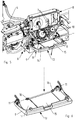
- Weitere Einzelheiten der Erfindung sind der Beispielsbeschreibung und den Zeichnungen zu entnehmen. Die Zeichnungen zeigen
- Fig.1
- landwirtschaftliche Feldspritze in perspektivischer Darstellung von schräg vorne,
- Fig.2
- das Bedienfeld einer landwirtschaftlichen Feldspritze mit Abdeckklappe in Abdeckposition in seitlicher Ansicht von links,
- Fig.3
- das Bedienfeld einer landwirtschaftlichen Feldspritze mit Abdeckklappe in Abdeckposition in perspektivischer Ansicht von der linken Seite,
- Fig.4
- das Bedienfeld einer landwirtschaftlichen Feldspritze mit Abdeckklappe in Arbeitsposition in seitlicher Ansicht von links,
- Fig.5
- das Bedienfeld einer landwirtschaftlichen Feldspritze mit Abdeckklappe in Arbeitsposition in perspektivischer Ansicht von der linken Seite und
- Fig.6
- die Abdeckklappe des Bedienfeldes einer landwirtschaftlichen Feldspritze in Arbeitsposition in perspektivischer Ansicht.
- Eine landwirtschaftliche Feldspritze 1 zum Ausbringen von Wirkstoffmitteln, vorzugsweise Pflanzenschutz- und/oder Düngemitteln, ist in
Fig. 1 gezeigt. Die Feldspritze 1 ist als gezogene Feldspritze 1 ausgebildet und wird von einem landwirtschaftlichen Zugfahrzeug gezogen. Ebenso kann die Feldspritze 1 auch zum Anbau an ein landwirtschaftliches Zugfahrzeug ausgebildet sein. - Die Feldspritze 1 weist einen Flüssigkeitsbehälter 2 auf, welcher über einen Rahmen auf Rädern 3 abgestützt ist. Der Flüssigkeitsbehälter 2 dient der Bevorratung der auszubringenden Spritzbrühe. Die Spritzbrühe setzt sich vorzugsweise aus Wasser als Trägerflüssigkeit zusammen, welcher in konzentrierter Form als Pulver, Feststoff und/oder Flüssigkeit vorliegende Wirkstoffmittel zugemischt werden.
- Das Zumischen der Wirkstoffmittel erfolgt in an sich bekannter Weise mithilfe einer Zumischvorrichtung 4, welche im Beispiel der
Fig. 1 bis 5 als Einspülschleuse ausgeführt ist. - Die angemischte und im Flüssigkeitsbehälter 2 bevorratete Spritzbrühe wird mittels an einem Gestänge 5 beabstandet zueinander angeordneten, als Spritzdüsen ausgeführten Ausbringelementen über einer landwirtschaftlichen Nutzfläche ausgebracht.
- Über einen nur teilweise in Form von Schlauchleitungen 6 dargestellten Flüssigkeitskreislauf sind der Flüssigkeitsbehälter 2, die Zumischvorrichtung 4 und die Ausbringelemente miteinander verbunden.
- Das Einstellen und/oder Steuern des Zumischens der Wirkstoffmittel und/oder des Befüllens des Flüssigkeitsbehälters erfolgt über die Einstell- und/oder Steuerarmaturen 7 eines Bedienfeldes 8, welches auf der in Fahrtrichtung F linken Seite der Feldspritze angeordnet ist, wie sie in den
Fig. 2 bis 5 gezeigt sind. Unter einer Abdeckklappe 9 umfasst das Bedienfeld 8 zudem Wartungsarmaturen 10 zur Instandhaltung der landwirtschaftlichen Feldspritze 1. In bevorzugter Weise umfassen die Wartungsarmaturen 10 die Filtereinrichtungen des Flüssigkeitskreislaufs. - Die Abdeckklappe 9 ist in ihrem unteren Bereich mittels Scharnieren 11 schwenkbar am Bedienfeld 8 der Feldspritze 1 angelenkt. Die Schwenkachse liegt dabei zumindest annähernd parallel zum Erdboden und ist zumindest annähernd parallel zur Fahrrichtung F ausgerichtet.
- Die Abdeckklappe 9 ist in eine Abdeckposition 12, wie sie die
Fig. 2 und 3 zeigt, sowie in eine Arbeitsposition 13, wie sie dieFig. 4 bis 6 zeigt, verbringbar und mittels geeigneter Mittel in beiden Positionen 12,13 feststell- und/oder festsetzbar. In Abdeckposition 12 deckt die Abdeckklappe 9 die Wartungsarmaturen 10 des Bedienfeldes 8 ab. Dadurch werden diese Wartungsarmaturen 10 besonders gut vor mechanischen Einwirkungen, Witterungseinflüssen und/oder Verschmutzungen geschützt. Gleichzeitig wird die Aufmerksamkeit des Bedieners auf die nicht abgedeckten, für Routinearbeiten notwendigen Einstell- und/oder Steuerarmaturen gelenkt. - Die Abdeckklappe 9 befindet sich während des Ausbringvorgangs und/oder während Transportfahrten in ihrer Abdeckposition 12. Für Wartungsarbeiten, beispielsweise einem Austausch der Filtereinrichtungen, wird die Abdeckklappe 9 in ihre Arbeitsposition 13 verbracht, wie es in den
Fig. 4 und5 gezeigt ist. - In ihrer Arbeitsposition 13 weist die Abdeckklappe 9 zumindest einen zumindest annähernd waagerecht orientierten Ablagebereich 14 auf. Dieser Ablagebereich 14 kann von einem Bediener während der Durchführung von Wartungsarbeiten genutzt werden, um Werkzeuge und/oder Austauschteile anzulegen, wodurch die dem Bediener die Durchführung der Arbeiten erheblich erleichtert wird.
- Im gezeigten Beispiel der
Fig. 2 bis 5 ist das Bedienfeld 8 im Bereich der Zumischvorrichtung 4 angeordnet. In bevorzugter Weise sind das Bedienfeld 8 und die Zumischvorrichtung 4 direkt benachbart. So hat der Bediener die Möglichkeit, die für das Zumischen der Wirkstoffmittel notwendigen Wirkstoffmittelgebinde und/oder Hilfsmittel, wie Waage und/oder Messbecher, auf dem Ablagebereich 14 abzustellen. Somit dient die Abdeckklappe 9 in ihrer Arbeitsstellung 13 als Arbeitstisch. - Eine Detailansicht der Abdeckklappe 9 in Arbeitsposition 13 zeigt
Fig. 6 . In bevorzugter Ausführungsform ist vorgesehen, dass auf dem Ablagebereich 14 der Abdeckklappe 9 eine Dokumentenhülle 15 lösbar befestigt ist. Die Befestigung erfolgt über geeignete Befestigungsmittel 16, die im Beispiel derFig. 5 und 6 als Flügelschrauben ausgebildet sind. - In der Dokumentenhülle 15 können beispielsweise Bedienungshandbücher zur Unterstützung der Wartungsarbeiten, Rezepturen für das Zumischen der Wirkstoffmittel und/oder Auftragsbücher mit Informationen zu anstehenden Arbeitsaufgaben untergebracht sein. In bevorzugter Ausführung ist die Dokumentenhülle 15 wasserdicht, sodass die enthaltenen Dokumente vor Feuchtigkeitseinflüssen geschützt sind.
Claims (9)
- Landwirtschaftliche Feldspritze (1) zum dosierten Ausbringen von Wirkstoffmitteln, vorzugsweise mit Wasser als Trägerflüssigkeit zu einer Spritzbrühe verdünnten Pflanzenschutz- und/oder Düngemitteln, aufweisend einen Flüssigkeitsbehälter (2) zur Bevorratung der auszubringenden Flüssigkeit, einen Flüssigkeitskreislauf (6) sowie Vorrichtungen, die geeignet sind, die Flüssigkeit dem Flüssigkeitskreislauf (6) zuzuführen, wobei die Bedienung des Flüssigkeitskreislaufes (6) mittels eines Bedienfeldes (8) erfolgt, wobei das Bedienfeld (8) in einen die Einstell- und/oder Steuerarmaturen (7) des Flüssigkeitskreislaufs (6) umfassenden Einstellbereich und einen weitere Einrichtungen, wie Wartungsarmaturen (10) und/oder Filtereinrichtungen, umfassenden Wartungsbereich unterteilt ist, dadurch gekennzeichnet, dass der Wartungsbereich mittels einer um eine Schwenkachse verschwenkbar angeordneten Abdeckklappe (9) abgedeckt ist und die Abdeckklappe (9) in eine die Wartungsarmaturen (10) abdeckende Abdeckposition (12) sowie in eine die Wartungsarmaturen (10) freigebende Arbeitsposition (13) bringbar ist und die Abdeckklappe (9) in ihrer Arbeitsposition (13) zumindest einen zumindest annähernd waagerecht orientierten Ablagebereich (14) aufweist.
- Landwirtschaftliche Feldspritze (1) nach Anspruch 1, dadurch gekennzeichnet, dass die Schwenkachse im unteren Bereich der Abdeckklappe (9) angeordnet ist.
- Landwirtschaftliche Feldspritze (1) nach zumindest einem der vorangegangenen Ansprüche dadurch gekennzeichnet, dass die Schwenkachse in zumindest annähernd waagerechter Richtung verläuft.
- Landwirtschaftliche Feldspritze (1) nach zumindest einem der vorangegangenen Ansprüche dadurch gekennzeichnet, dass die Abdeckklappe (9) in ihrer Abdeck-(12) und ihrer Arbeitsposition (13) feststell- und/oder festsetzbar ist.
- Landwirtschaftliche Feldspritze (1) nach zumindest einem der vorangegangenen Ansprüche dadurch gekennzeichnet, dass die Abdeckklappe (9) geeignet ist, in ihrer Arbeitsposition (13) dem Bediener der Feldspritze (1) als Arbeitstisch zu dienen.
- Landwirtschaftliche Feldspritze (1) nach zumindest einem der vorangegangenen Ansprüche dadurch gekennzeichnet, dass auf dem Ablagebereich (14) der Abdeckklappe (9) eine Dokumentenhülle (15) befestigt ist.
- Landwirtschaftliche Feldspritze (1) nach zumindest einem der vorangegangenen Ansprüche dadurch gekennzeichnet, dass auf dem Ablagebereich (14) der Abdeckklappe (9) eine Dokumentenhülle (15) lösbar befestigt ist.
- Landwirtschaftliche Feldspritze (1) nach zumindest einem der vorangegangenen Ansprüche dadurch gekennzeichnet, dass die Dokumentenhülle (15) wasserdicht ist.
- Landwirtschaftliche Feldspritze (1) nach zumindest einem der vorangegangenen Ansprüche, wobei die Feldspritze eine Zumischvorrichtung (4) aufweist, die geeignet ist, der Trägerflüssigkeit die Pflanzenschutz- und/oder Düngemittel zuzumischen, dadurch gekennzeichnet, dass das Bedienfeld (8) im Bereich oder in der Nähe der Zumischvorrichtung (4) angeordnet ist.
Priority Applications (1)
| Application Number | Priority Date | Filing Date | Title |
|---|---|---|---|
| PL17401076T PL3272215T3 (pl) | 2016-07-19 | 2017-07-14 | Rolniczy opryskiwacz polowy |
Applications Claiming Priority (1)
| Application Number | Priority Date | Filing Date | Title |
|---|---|---|---|
| DE102016113233.0A DE102016113233A1 (de) | 2016-07-19 | 2016-07-19 | Landwirtschaftliche Feldspritze |
Publications (3)
| Publication Number | Publication Date |
|---|---|
| EP3272215A1 true EP3272215A1 (de) | 2018-01-24 |
| EP3272215B1 EP3272215B1 (de) | 2021-03-24 |
| EP3272215B8 EP3272215B8 (de) | 2021-05-26 |
Family
ID=59592991
Family Applications (1)
| Application Number | Title | Priority Date | Filing Date |
|---|---|---|---|
| EP17401076.9A Active EP3272215B8 (de) | 2016-07-19 | 2017-07-14 | Landwirtschaftliche feldspritze |
Country Status (4)
| Country | Link |
|---|---|
| EP (1) | EP3272215B8 (de) |
| DE (1) | DE102016113233A1 (de) |
| DK (1) | DK3272215T3 (de) |
| PL (1) | PL3272215T3 (de) |
Citations (3)
| Publication number | Priority date | Publication date | Assignee | Title |
|---|---|---|---|---|
| DE202006010074U1 (de) * | 2006-06-28 | 2007-11-08 | Amazonen-Werke H. Dreyer Gmbh & Co. Kg | Landwirtschaftliche Feldspritze |
| US20090014447A1 (en) * | 2007-07-10 | 2009-01-15 | Cnh America Llc | Latching Assembly for a Pressurized Tank Cover |
| EP2923570A1 (de) | 2014-03-28 | 2015-09-30 | Amazonen-Werke H. Dreyer GmbH & Co. KG | Landwirtschaftliche feldspritze |
-
2016
- 2016-07-19 DE DE102016113233.0A patent/DE102016113233A1/de not_active Withdrawn
-
2017
- 2017-07-14 DK DK17401076.9T patent/DK3272215T3/da active
- 2017-07-14 EP EP17401076.9A patent/EP3272215B8/de active Active
- 2017-07-14 PL PL17401076T patent/PL3272215T3/pl unknown
Patent Citations (3)
| Publication number | Priority date | Publication date | Assignee | Title |
|---|---|---|---|---|
| DE202006010074U1 (de) * | 2006-06-28 | 2007-11-08 | Amazonen-Werke H. Dreyer Gmbh & Co. Kg | Landwirtschaftliche Feldspritze |
| US20090014447A1 (en) * | 2007-07-10 | 2009-01-15 | Cnh America Llc | Latching Assembly for a Pressurized Tank Cover |
| EP2923570A1 (de) | 2014-03-28 | 2015-09-30 | Amazonen-Werke H. Dreyer GmbH & Co. KG | Landwirtschaftliche feldspritze |
Also Published As
| Publication number | Publication date |
|---|---|
| PL3272215T3 (pl) | 2021-10-04 |
| EP3272215B1 (de) | 2021-03-24 |
| DE102016113233A1 (de) | 2018-01-25 |
| EP3272215B8 (de) | 2021-05-26 |
| DK3272215T3 (da) | 2021-06-21 |
Similar Documents
| Publication | Publication Date | Title |
|---|---|---|
| EP2022329A2 (de) | Fahrbare Spritzanordnung mit einem Spritzgestänge und Verfahren zur Einstellung deren Spritzdüsen | |
| DE69022147T2 (de) | Streuer. | |
| DE60313638T2 (de) | Zusammensetzung und Düngerstreumaschine zum Durchführen einer Verteilung von Dünger | |
| DE3050904C2 (de) | ||
| DE1782939A1 (de) | Streugeraet | |
| DE2719405A1 (de) | Maschine zum ausbringen von duengemitteln | |
| EP3272215B1 (de) | Landwirtschaftliche feldspritze | |
| DE3532756C1 (en) | Broadcaster, especially for granular fertilizers | |
| DE1782793A1 (de) | Kreisel-heuwerbungsmaschine | |
| DE69708561T2 (de) | Streuer für körniges und/oder pulveriges Gut | |
| EP3262913B1 (de) | Landwirtschaftliche verteilmaschine mit bedienzentrum | |
| DE1457850A1 (de) | Kunstduengerstreuer | |
| DE2008016A1 (de) | Landwirtschaftliches Gerät | |
| DE3512992A1 (de) | Vorrichtung zum streuen von schuettfaehigem gut, insbesondere duenger | |
| DE3103686C2 (de) | ||
| DE4109846A1 (de) | Schleuderduengerstreuer | |
| DE1892814U (de) | Einlauftrichter fuer waagen. | |
| DE10011401A1 (de) | Landwirtschaftliche Verteilmaschine | |
| DE477164C (de) | Vorrichtung zur Bekaempfung von Schaedlingen von Luftfahrzeugen aus | |
| DE875589C (de) | Verfahren und Vorrichtung zur Schaedlingsbekaempfung von Pflanzen durch Bespruehen | |
| DE869134C (de) | Zusammenlegbarer Giessbehaelter | |
| DE3018805A1 (de) | Streugeraet zum ausstreuen von koernigem und/oder pulverigem gut | |
| DE2111168A1 (de) | Einfaltbarer Erweiterungsaufbau fuer den Korntank an Maehdreschern | |
| DE1998710U (de) | Maehmaschine, insbesondere schlepperanbaumahwerk. | |
| DE4206301A1 (de) | Verfahren und vorrichtung zur regelung der streubreite einer schleuderstreumaschine fuer koernige erzeugnisse auf einen bestimmten wert |
Legal Events
| Date | Code | Title | Description |
|---|---|---|---|
| PUAI | Public reference made under article 153(3) epc to a published international application that has entered the european phase |
Free format text: ORIGINAL CODE: 0009012 |
|
| STAA | Information on the status of an ep patent application or granted ep patent |
Free format text: STATUS: THE APPLICATION HAS BEEN PUBLISHED |
|
| AK | Designated contracting states |
Kind code of ref document: A1 Designated state(s): AL AT BE BG CH CY CZ DE DK EE ES FI FR GB GR HR HU IE IS IT LI LT LU LV MC MK MT NL NO PL PT RO RS SE SI SK SM TR |
|
| AX | Request for extension of the european patent |
Extension state: BA ME |
|
| STAA | Information on the status of an ep patent application or granted ep patent |
Free format text: STATUS: REQUEST FOR EXAMINATION WAS MADE |
|
| 17P | Request for examination filed |
Effective date: 20180613 |
|
| RBV | Designated contracting states (corrected) |
Designated state(s): AL AT BE BG CH CY CZ DE DK EE ES FI FR GB GR HR HU IE IS IT LI LT LU LV MC MK MT NL NO PL PT RO RS SE SI SK SM TR |
|
| GRAP | Despatch of communication of intention to grant a patent |
Free format text: ORIGINAL CODE: EPIDOSNIGR1 |
|
| STAA | Information on the status of an ep patent application or granted ep patent |
Free format text: STATUS: GRANT OF PATENT IS INTENDED |
|
| INTG | Intention to grant announced |
Effective date: 20201117 |
|
| GRAS | Grant fee paid |
Free format text: ORIGINAL CODE: EPIDOSNIGR3 |
|
| GRAA | (expected) grant |
Free format text: ORIGINAL CODE: 0009210 |
|
| STAA | Information on the status of an ep patent application or granted ep patent |
Free format text: STATUS: THE PATENT HAS BEEN GRANTED |
|
| AK | Designated contracting states |
Kind code of ref document: B1 Designated state(s): AL AT BE BG CH CY CZ DE DK EE ES FI FR GB GR HR HU IE IS IT LI LT LU LV MC MK MT NL NO PL PT RO RS SE SI SK SM TR |
|
| REG | Reference to a national code |
Ref country code: GB Ref legal event code: FG4D Free format text: NOT ENGLISH |
|
| REG | Reference to a national code |
Ref country code: CH Ref legal event code: EP |
|
| REG | Reference to a national code |
Ref country code: DE Ref legal event code: R081 Ref document number: 502017009796 Country of ref document: DE Owner name: AMAZONEN-WERKE H. DREYER SE & CO. KG, DE Free format text: FORMER OWNER: AMAZONEN-WERKE H. DREYER GMBH & CO. KG, 49205 HASBERGEN, DE Ref country code: IE Ref legal event code: FG4D Free format text: LANGUAGE OF EP DOCUMENT: GERMAN |
|
| REG | Reference to a national code |
Ref country code: DE Ref legal event code: R096 Ref document number: 502017009796 Country of ref document: DE Ref country code: CH Ref legal event code: PK Free format text: BERICHTIGUNG B8 Ref country code: AT Ref legal event code: REF Ref document number: 1373542 Country of ref document: AT Kind code of ref document: T Effective date: 20210415 |
|
| RAP4 | Party data changed (patent owner data changed or rights of a patent transferred) |
Owner name: AMAZONEN-WERK H. DREYER SE & CO. KG |
|
| REG | Reference to a national code |
Ref country code: CH Ref legal event code: PK Free format text: BERICHTIGUNG B8 |
|
| RAP4 | Party data changed (patent owner data changed or rights of a patent transferred) |
Owner name: AMAZONEN-WERKE H. DREYER SE & CO. KG |
|
| REG | Reference to a national code |
Ref country code: NL Ref legal event code: FP |
|
| REG | Reference to a national code |
Ref country code: DK Ref legal event code: T3 Effective date: 20210614 |
|
| REG | Reference to a national code |
Ref country code: LT Ref legal event code: MG9D |
|
| PG25 | Lapsed in a contracting state [announced via postgrant information from national office to epo] |
Ref country code: NO Free format text: LAPSE BECAUSE OF FAILURE TO SUBMIT A TRANSLATION OF THE DESCRIPTION OR TO PAY THE FEE WITHIN THE PRESCRIBED TIME-LIMIT Effective date: 20210624 Ref country code: GR Free format text: LAPSE BECAUSE OF FAILURE TO SUBMIT A TRANSLATION OF THE DESCRIPTION OR TO PAY THE FEE WITHIN THE PRESCRIBED TIME-LIMIT Effective date: 20210625 Ref country code: HR Free format text: LAPSE BECAUSE OF FAILURE TO SUBMIT A TRANSLATION OF THE DESCRIPTION OR TO PAY THE FEE WITHIN THE PRESCRIBED TIME-LIMIT Effective date: 20210324 Ref country code: FI Free format text: LAPSE BECAUSE OF FAILURE TO SUBMIT A TRANSLATION OF THE DESCRIPTION OR TO PAY THE FEE WITHIN THE PRESCRIBED TIME-LIMIT Effective date: 20210324 Ref country code: BG Free format text: LAPSE BECAUSE OF FAILURE TO SUBMIT A TRANSLATION OF THE DESCRIPTION OR TO PAY THE FEE WITHIN THE PRESCRIBED TIME-LIMIT Effective date: 20210624 |
|
| PG25 | Lapsed in a contracting state [announced via postgrant information from national office to epo] |
Ref country code: SE Free format text: LAPSE BECAUSE OF FAILURE TO SUBMIT A TRANSLATION OF THE DESCRIPTION OR TO PAY THE FEE WITHIN THE PRESCRIBED TIME-LIMIT Effective date: 20210324 Ref country code: LV Free format text: LAPSE BECAUSE OF FAILURE TO SUBMIT A TRANSLATION OF THE DESCRIPTION OR TO PAY THE FEE WITHIN THE PRESCRIBED TIME-LIMIT Effective date: 20210324 Ref country code: RS Free format text: LAPSE BECAUSE OF FAILURE TO SUBMIT A TRANSLATION OF THE DESCRIPTION OR TO PAY THE FEE WITHIN THE PRESCRIBED TIME-LIMIT Effective date: 20210324 |
|
| PG25 | Lapsed in a contracting state [announced via postgrant information from national office to epo] |
Ref country code: EE Free format text: LAPSE BECAUSE OF FAILURE TO SUBMIT A TRANSLATION OF THE DESCRIPTION OR TO PAY THE FEE WITHIN THE PRESCRIBED TIME-LIMIT Effective date: 20210324 Ref country code: LT Free format text: LAPSE BECAUSE OF FAILURE TO SUBMIT A TRANSLATION OF THE DESCRIPTION OR TO PAY THE FEE WITHIN THE PRESCRIBED TIME-LIMIT Effective date: 20210324 Ref country code: SM Free format text: LAPSE BECAUSE OF FAILURE TO SUBMIT A TRANSLATION OF THE DESCRIPTION OR TO PAY THE FEE WITHIN THE PRESCRIBED TIME-LIMIT Effective date: 20210324 |
|
| PG25 | Lapsed in a contracting state [announced via postgrant information from national office to epo] |
Ref country code: PT Free format text: LAPSE BECAUSE OF FAILURE TO SUBMIT A TRANSLATION OF THE DESCRIPTION OR TO PAY THE FEE WITHIN THE PRESCRIBED TIME-LIMIT Effective date: 20210726 Ref country code: RO Free format text: LAPSE BECAUSE OF FAILURE TO SUBMIT A TRANSLATION OF THE DESCRIPTION OR TO PAY THE FEE WITHIN THE PRESCRIBED TIME-LIMIT Effective date: 20210324 Ref country code: SK Free format text: LAPSE BECAUSE OF FAILURE TO SUBMIT A TRANSLATION OF THE DESCRIPTION OR TO PAY THE FEE WITHIN THE PRESCRIBED TIME-LIMIT Effective date: 20210324 Ref country code: IS Free format text: LAPSE BECAUSE OF FAILURE TO SUBMIT A TRANSLATION OF THE DESCRIPTION OR TO PAY THE FEE WITHIN THE PRESCRIBED TIME-LIMIT Effective date: 20210724 |
|
| REG | Reference to a national code |
Ref country code: DE Ref legal event code: R097 Ref document number: 502017009796 Country of ref document: DE |
|
| PG25 | Lapsed in a contracting state [announced via postgrant information from national office to epo] |
Ref country code: AL Free format text: LAPSE BECAUSE OF FAILURE TO SUBMIT A TRANSLATION OF THE DESCRIPTION OR TO PAY THE FEE WITHIN THE PRESCRIBED TIME-LIMIT Effective date: 20210324 Ref country code: ES Free format text: LAPSE BECAUSE OF FAILURE TO SUBMIT A TRANSLATION OF THE DESCRIPTION OR TO PAY THE FEE WITHIN THE PRESCRIBED TIME-LIMIT Effective date: 20210324 |
|
| PLBE | No opposition filed within time limit |
Free format text: ORIGINAL CODE: 0009261 |
|
| STAA | Information on the status of an ep patent application or granted ep patent |
Free format text: STATUS: NO OPPOSITION FILED WITHIN TIME LIMIT |
|
| PG25 | Lapsed in a contracting state [announced via postgrant information from national office to epo] |
Ref country code: SI Free format text: LAPSE BECAUSE OF FAILURE TO SUBMIT A TRANSLATION OF THE DESCRIPTION OR TO PAY THE FEE WITHIN THE PRESCRIBED TIME-LIMIT Effective date: 20210324 |
|
| REG | Reference to a national code |
Ref country code: CH Ref legal event code: PL |
|
| 26N | No opposition filed |
Effective date: 20220104 |
|
| PG25 | Lapsed in a contracting state [announced via postgrant information from national office to epo] |
Ref country code: MC Free format text: LAPSE BECAUSE OF FAILURE TO SUBMIT A TRANSLATION OF THE DESCRIPTION OR TO PAY THE FEE WITHIN THE PRESCRIBED TIME-LIMIT Effective date: 20210324 |
|
| REG | Reference to a national code |
Ref country code: BE Ref legal event code: MM Effective date: 20210731 |
|
| PG25 | Lapsed in a contracting state [announced via postgrant information from national office to epo] |
Ref country code: LI Free format text: LAPSE BECAUSE OF NON-PAYMENT OF DUE FEES Effective date: 20210731 Ref country code: CH Free format text: LAPSE BECAUSE OF NON-PAYMENT OF DUE FEES Effective date: 20210731 |
|
| PG25 | Lapsed in a contracting state [announced via postgrant information from national office to epo] |
Ref country code: IS Free format text: LAPSE BECAUSE OF FAILURE TO SUBMIT A TRANSLATION OF THE DESCRIPTION OR TO PAY THE FEE WITHIN THE PRESCRIBED TIME-LIMIT Effective date: 20210724 Ref country code: LU Free format text: LAPSE BECAUSE OF NON-PAYMENT OF DUE FEES Effective date: 20210714 |
|
| PG25 | Lapsed in a contracting state [announced via postgrant information from national office to epo] |
Ref country code: IE Free format text: LAPSE BECAUSE OF NON-PAYMENT OF DUE FEES Effective date: 20210714 Ref country code: BE Free format text: LAPSE BECAUSE OF NON-PAYMENT OF DUE FEES Effective date: 20210731 |
|
| PG25 | Lapsed in a contracting state [announced via postgrant information from national office to epo] |
Ref country code: HU Free format text: LAPSE BECAUSE OF FAILURE TO SUBMIT A TRANSLATION OF THE DESCRIPTION OR TO PAY THE FEE WITHIN THE PRESCRIBED TIME-LIMIT; INVALID AB INITIO Effective date: 20170714 |
|
| P01 | Opt-out of the competence of the unified patent court (upc) registered |
Effective date: 20230523 |
|
| PG25 | Lapsed in a contracting state [announced via postgrant information from national office to epo] |
Ref country code: CY Free format text: LAPSE BECAUSE OF FAILURE TO SUBMIT A TRANSLATION OF THE DESCRIPTION OR TO PAY THE FEE WITHIN THE PRESCRIBED TIME-LIMIT Effective date: 20210324 |
|
| PGFP | Annual fee paid to national office [announced via postgrant information from national office to epo] |
Ref country code: IT Payment date: 20230612 Year of fee payment: 7 |
|
| REG | Reference to a national code |
Ref country code: AT Ref legal event code: MM01 Ref document number: 1373542 Country of ref document: AT Kind code of ref document: T Effective date: 20220714 |
|
| PG25 | Lapsed in a contracting state [announced via postgrant information from national office to epo] |
Ref country code: AT Free format text: LAPSE BECAUSE OF NON-PAYMENT OF DUE FEES Effective date: 20220714 |
|
| PGFP | Annual fee paid to national office [announced via postgrant information from national office to epo] |
Ref country code: GB Payment date: 20230601 Year of fee payment: 7 |
|
| PG25 | Lapsed in a contracting state [announced via postgrant information from national office to epo] |
Ref country code: MK Free format text: LAPSE BECAUSE OF FAILURE TO SUBMIT A TRANSLATION OF THE DESCRIPTION OR TO PAY THE FEE WITHIN THE PRESCRIBED TIME-LIMIT Effective date: 20210324 |
|
| PG25 | Lapsed in a contracting state [announced via postgrant information from national office to epo] |
Ref country code: MT Free format text: LAPSE BECAUSE OF FAILURE TO SUBMIT A TRANSLATION OF THE DESCRIPTION OR TO PAY THE FEE WITHIN THE PRESCRIBED TIME-LIMIT Effective date: 20210324 |
|
| GBPC | Gb: european patent ceased through non-payment of renewal fee |
Effective date: 20240714 |
|
| PG25 | Lapsed in a contracting state [announced via postgrant information from national office to epo] |
Ref country code: GB Free format text: LAPSE BECAUSE OF NON-PAYMENT OF DUE FEES Effective date: 20240714 |
|
| PGFP | Annual fee paid to national office [announced via postgrant information from national office to epo] |
Ref country code: PL Payment date: 20250612 Year of fee payment: 9 |
|
| PG25 | Lapsed in a contracting state [announced via postgrant information from national office to epo] |
Ref country code: IT Free format text: LAPSE BECAUSE OF NON-PAYMENT OF DUE FEES Effective date: 20240714 |
|
| PGFP | Annual fee paid to national office [announced via postgrant information from national office to epo] |
Ref country code: NL Payment date: 20250613 Year of fee payment: 9 |
|
| PGFP | Annual fee paid to national office [announced via postgrant information from national office to epo] |
Ref country code: FR Payment date: 20250610 Year of fee payment: 9 |
|
| PGFP | Annual fee paid to national office [announced via postgrant information from national office to epo] |
Ref country code: CZ Payment date: 20250618 Year of fee payment: 9 |
|
| PGFP | Annual fee paid to national office [announced via postgrant information from national office to epo] |
Ref country code: DK Payment date: 20250714 Year of fee payment: 9 Ref country code: DE Payment date: 20250604 Year of fee payment: 9 |
|
| PG25 | Lapsed in a contracting state [announced via postgrant information from national office to epo] |
Ref country code: TR Free format text: LAPSE BECAUSE OF FAILURE TO SUBMIT A TRANSLATION OF THE DESCRIPTION OR TO PAY THE FEE WITHIN THE PRESCRIBED TIME-LIMIT Effective date: 20210324 |