EP3262912B1 - Landwirtschaftliche verteilmaschine mit abdeckung - Google Patents
Landwirtschaftliche verteilmaschine mit abdeckung Download PDFInfo
- Publication number
- EP3262912B1 EP3262912B1 EP17401066.0A EP17401066A EP3262912B1 EP 3262912 B1 EP3262912 B1 EP 3262912B1 EP 17401066 A EP17401066 A EP 17401066A EP 3262912 B1 EP3262912 B1 EP 3262912B1
- Authority
- EP
- European Patent Office
- Prior art keywords
- covering
- metering member
- metering
- cover
- spreader machine
- Prior art date
- Legal status (The legal status is an assumption and is not a legal conclusion. Google has not performed a legal analysis and makes no representation as to the accuracy of the status listed.)
- Active
Links
Images

Classifications
-
- A—HUMAN NECESSITIES
- A01—AGRICULTURE; FORESTRY; ANIMAL HUSBANDRY; HUNTING; TRAPPING; FISHING
- A01C—PLANTING; SOWING; FERTILISING
- A01C7/00—Sowing
- A01C7/08—Broadcast seeders; Seeders depositing seeds in rows
- A01C7/12—Seeders with feeding wheels
- A01C7/123—Housings for feed rollers or wheels
Definitions
- the invention relates to an agricultural distribution machine according to the preamble of claim 1.
- Such a distributor is in the DE 43 32 159 A1 described.
- the distributor described has a reservoir, which is associated with at least one metering.
- the at least one metering device feeds the material to be distributed in adjustable quantities via adjustable guide elements into delivery lines leading to discharge organs.
- the guide members are suitably positioned in an operating position to serve as a cover of the metering. This prevents that driven parts of the metering device are freely accessible.
- a calibration is performed. For the calibration process, the guide elements are moved to a suitable calibration position or maintenance position in order to guide the metered material past the delivery lines into a calibration container.
- the US 2010/0307394 A1 shows a metering device, the metering means are covered by covers. From the covers protrude drive elements that are electronically controlled.
- the invention is therefore based on the object to provide an arrangement in which settings can be made when covered by a cover metering.
- Distribution machines are known from the prior art in which the driven parts of the metering members are covered by a suitable arrangement of the calibration container during the distribution process. According to the invention, such an arrangement is not provided.
- the calibration containers of the distribution machine according to the invention are therefore provided exclusively for the purpose intended for them during the calibration process and are arranged at an optimum point of the machine outside the calibration process during the distribution process.
- the cover of the invention is separate components in addition to the calibration.
- the cover is designed to be pivotable as a cover flap and in an operating position covering the driven parts of the at least one metering and in a maintenance position releasing the driven parts of the at least one metering.
- an operator also has the option to perform the maintenance of the driven parts of the dosing when required.
- Driven or moving parts are, for example, metering wheels and / or rollers, the countershaft, including gears, and any chain hoists on the gears. Maintenance may be due to wear or contamination.
- the distributor is common that parts of the metering be replaced before a distribution process, for example, to adapt the metering to the specific grain sizes of various shadowder materials.
- the cover can be moved from its operating position into its maintenance position only with conscious use of a suitable tool. This ensures the maximum possible occupational safety for an operator. It is impossible that carelessness or lack of expertise gives access to the driven parts of the metering devices.
- a further advantageous embodiment is given by the fact that the pivotable cover is articulated in the region of the at least one dosing on the reservoir or on the dosing by means of hinge elements.
- the cover is easy to open for an operator and does not have to be completely removed or attached.
- the cover can be easily moved between operating position and maintenance position.
- a particularly compact design can be achieved if the pivot axis of the cover corresponds at least approximately to the axis of rotation of the countershaft of the drive of the at least one metering.
- the cover has in its the driven parts of the at least one metering releasing maintenance position a flat, at least approximately parallel to the ground extending region.
- a particular advantage is achieved in that the flat, in maintenance position at least approximately parallel to the ground extending portion of the cover is usable as a storage area.
- This configuration makes it possible for an operator to perform and / or provide tools and / or replaceable components for the work process while carrying out maintenance work. This increases the comfort during such work considerably. Unnecessary ways are saved and the danger that components and / or tools fall to the ground, get lost or are inaccessible to the working operator decreases.
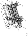
- An agricultural distributor 1 which in the example chosen the Fig. 1 to 5 is designed as a seeder, has a reservoir 2 for storing material to be distributed.
- the reservoir 2 is supported by means of support elements 3 on the frame 4 of a distributor unit 1 associated with the roller unit 5, such as Fig. 1 shows.
- the lower region of the storage container 2 is designed as a discharge region, in which outlet openings, not shown, are arranged.
- About the outlet openings the material to be distributed is delivered to Ausbringorganen 6 leading conveyor lines 7.
- a plurality of dosing 8 are arranged.
- the output to the delivery lines 7 amount of material to be distributed is set.
- Abwind investigatinger 7A are arranged to perform a calibration process.
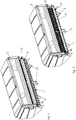
- a cover cover 9 In the area of the dosing 8 a designed as a cover cover 9 is arranged.
- the cover 9 is articulated pivotably on the storage container 2 or on the metering members 8.
- the fastening elements 10 in cooperation with their container-side counterparts for pivoting the cover 9 suitable joint elements.
- the pivot axis is horizontal and coincides substantially with the longitudinal axis of the countershaft of the metering 8.
- the cover 9 covers the driven parts of the metering 8.
- Energized parts of the metering 8 are, for example, metering wheels and / or rollers, the countershaft, including gears and possibly running on the gears chain hoists. The adjustment of the metering 8 are still accessible to the operator of the distributor 1.
- the cover 9 In the maintenance position 12 of the cover 9 and the driven parts of the metering 8 are accessible. Since driven machine parts fundamentally pose a risk of injury to the operator and thus a source of danger, the cover 9 can be moved from the operating position 11 into the maintenance position 12 only with the conscious use of a suitable tool by the operator.
- the cover 9 is in its maintenance position 12, it has a horizontally oriented above the ground storage area 13.
- the storage area 13 is suitable for maintenance work of the operator in the area of the metering 8 for temporary storage of, for example, interchangeable components and / or tools.
- the cover 9 is not intended for use for the calibration process.
- To carry out the Abthermvorgangs Abform constitutioner are designed as separate containers.
Landscapes
- Life Sciences & Earth Sciences (AREA)
- Soil Sciences (AREA)
- Environmental Sciences (AREA)
- Catching Or Destruction (AREA)
- Filling Or Emptying Of Bunkers, Hoppers, And Tanks (AREA)
Description
- Die Erfindung betrifft eine landwirtschaftliche Verteilmaschine gemäß des Oberbegriffes des Patentanspruches 1.
- Eine derartige Verteilmaschine ist in der
DE 43 32 159 A1 beschrieben. Die beschriebene Verteilmaschine weist einen Vorratsbehälter auf, welchem zumindest ein Dosierorgan zugeordnet ist. Das zumindest eine Dosierorgan speist während des Verteilvorgangs das zu verteilende Material in einstellbaren Mengen über einstellbare Leitorgane in zu Ausbringorganen führende Förderleitungen ein. Dabei sind die Leitorgane in einer Betriebsposition geeignet positioniert, um als Abdeckung des Dosierorgans zu dienen. Dies verhindert, dass angetriebene Teile des Dosierorgans frei zugänglich sind. Zur Kalibrierung des Dosierorgans wird ein Abdrehvorgang durchgeführt. Für den Abdrehvorgang werden die Leitorgane in eine geeignete Abdrehposition bzw. Wartungsposition verbracht, um das dosierte Material an den Förderleitungen vorbei in einen Abdrehbehälter zu leiten. - Nachteilig bei einer derartigen Anordnung ist die aufwändige Kinematik, mit der die Leitorgane zwischen ihrer Betriebsposition und der Wartungsposition verbracht werden. Zusätzlich ist nachteilig, dass das zumindest eine Dosierorgan samt seiner Einstellelemente durch die sich in ihrer Betriebsposition befindlichen Leitorgane verdeckt werden. Dadurch ist während des Verteilvorgangs keine zeiteffiziente Korrektur der Dosiereinstellungen möglich. Stets müssen für eine Korrektur der Einstellungen die Leitorgane umständlich in ihre Wartungsposition verbracht werden, damit der Zugang zu den Einstellelementen des Dosierorgans frei ist.
- Etwas Ähnliches zeigen die
US 5 915 312 A sowie dieUS 2015/271988 A1 : zur Wartung oder Einstellung der Dosierorgane ist in unkomfortabler Weise eine verschraubte Abdeckung zu entfernen. - Die
US 2010/0307394 A1 zeigt eine Dosiereinrichtung, deren Dosierorgane mittels Abdeckungen abgedeckt sind. Aus den Abdeckungen ragen Antriebselemente heraus, die elektronisch angesteuert. - Der Erfindung liegt daher die Aufgabe zugrunde, eine Anordnung bereitzustellen, bei der bei mittels einer Abdeckung abgedecktem Dosierorgan Einstellungen vorgenommen werden können.
- Erfindungsgemäß wird diese Aufgabe durch den kennzeichnenden Teil des Anspruchs 1 gelöst.
- Aus dem Stand der Technik sind Verteilmaschinen bekannt, bei denen während des Verteilvorgangs die angetriebenen Teile der Dosierorgane mittels einer geeigneten Anordnung der Abdrehbehälter abgedeckt werden. Erfindungsgemäß ist eine derartige Anordnung nicht vorgesehen. Die Abdrehbehälter der erfindungsgemäßen Verteilmaschine sind daher ausschließlich für die ihnen während des Abdrehvorgangs zugedachte Nutzung vorgesehen und werden an einer optimalen Stelle der Maschine außerhalb des Abdrehvorgangs während des Verteilvorgangs angeordnet. Bei der erfindungsgemäßen Abdeckung handelt es sich um separate Bauteile zusätzlich zu dem Abdrehbehälter.
- Da sich ein Bediener bei Arbeiten an den Dosierorganen beispielsweise mit seinen Händen in den angetriebenen Teilen der Dosierorgane verfangen kann, stellen diese eine signifikante Gefahrenquelle dar. Aus der erfindungsgemäßen Ausgestaltung der Abdeckung ergibt sich der Vorteil, dass die angetriebenen Teile zu jedem Zeitpunkt der Einstellarbeiten an den Dosierorganen abgedeckt sind und eine Einstellung mittels der freiliegenden Einstellelemente ungehindert möglich ist. Somit steigt die Arbeitssicherheit für einen Bediener deutlich.
- Gleichzeitig bietet eine stetige Abdeckung der angetriebenen Teile der Dosierorgane einen verbesserten Schutz dieser Teile vor Verunreinigungen. Gelangt Schmutz in angetriebene und/oder bewegliche Teile einer Maschine, kann deren Funktion beeinträchtig und/oder deren Verschleiß begünstigt werden.
- Ein besonderer Vorteil ergibt sich dadurch, dass die Abdeckung verschwenkbar als Abdeckklappe ausgeführt ist und in eine die angetriebenen Teile des zumindest einen Dosierorgans abdeckende Betriebsposition und in eine die angetriebenen Teile des zumindest einen Dosierorgans freigebende Wartungsposition verbringbar ist. Durch diese Ausgestaltung hat ein Bediener zusätzlich die Möglichkeit, bei Bedarf die Wartung der angetriebenen Teile der Dosierorgane vorzunehmen. Angetriebene bzw. bewegliche Teile sind beispielsweise Dosierräder und/oder -walzen, die Vorgelegewelle samt Zahnrädern und etwaig auf den Zahnrädern laufende Kettenzüge. Wartungsarbeiten können aufgrund von Verschleiß oder Verschmutzung anfallen. Ferner ist es für einen vielseitigen Einsatz der Verteilmaschine üblich, dass Teile der Dosierorgane vor einem Verteilvorgang ausgetauscht werden, beispielsweise zur Anpassung der Dosierorgane auf die spezifischen Korngrößen verschiedener auszubringender Materialien.
- Sind derartige Arbeiten notwendig, erweist sich als vorteilhaft, dass die Abdeckung ausschließlich unter bewusster Nutzung eines geeigneten Werkzeugs von ihrer Betriebsposition in ihre Wartungsposition verbringbar ist. Dadurch wird für einen Bediener die maximal mögliche Arbeitssicherheit sichergestellt. Es ist ausgeschlossen, dass durch Unachtsamkeit oder mangelnde Sachkenntnis Zugang zu den angetriebenen Teilen der Dosierorgane erlangt wird.
- Eine weitere vorteilhafte Ausgestaltung ist dadurch gegeben, dass die verschwenkbare Abdeckung im Bereich des zumindest einen Dosierorgans am Vorratsbehälter oder am Dosierorgan mittels Gelenkelementen angelenkt ist. Dadurch ist für einen Bediener die Abdeckung komfortabel zu öffnen und muss nicht aufwändig vollständig ab- bzw. angebaut werden. Zusätzlich kann die Abdeckung leicht zwischen Betriebsposition und Wartungsposition verbracht werden.
- In vorteilhafter Weise kann eine besonders kompakte Bauform erreicht werden, wenn die Schwenkachse der Abdeckklappe zumindest annähernd der Rotationsachse der Vorgelegewelle des Antriebs des zumindest einen Dosierorgans entspricht.
- Für Wartungsarbeiten an den angetriebenen Teilen des Dosierorgans ist es von Vorteil, dass die Abdeckung in ihrer die angetriebenen Teile des zumindest einen Dosierorgans freigebenden Wartungsposition einen ebenen, zumindest annähernd parallel zum Erdboden verlaufenden Bereich aufweist.
- Ein besonderer Vorteil wird dadurch erreicht, dass der ebene, in Wartungsposition zumindest annähernd parallel zum Erdboden verlaufende Bereich der Abdeckung als Ablagefläche nutzbar ist. Durch diese Ausgestaltung ist es einem Bediener während der Durchführung von Wartungsarbeiten möglich, Werkzeuge und/oder austauschbare Bauteile für den Arbeitsprozess ab und/oder bereit zu legen. Dies erhöht den Komfort während derartiger Arbeiten erheblich. Unnötige Wege werden eingespart und die Gefahr, dass Bauteile und/oder Werkzeug zu Boden fallen, verloren gehen oder für den arbeitenden Bediener unerreichbar sind, sinkt.
- Weitere Einzelheiten der Erfindung sind der Beispielsbeschreibung und den Zeichnungen zu entnehmen. Die Zeichnungen zeigen
- Fig.1
- wesentliche Teile einer landwirtschaftlichen Verteilmaschine in perspektivischer Ansicht von schräg hinten,
- Fig.2
- einen Vorratsbehälter der Verteilmaschine mit Abdeckung in Betriebsposition in perspektivischer Ansicht von schräg hinten,
- Fig.3
- einen Vorratsbehälter der Verteilmaschine mit Abdeckung in Wartungsposition in perspektivischer Ansicht von schräg hinten,
- Fig.4
- Abdeckung in Betriebsposition in perspektivischer Ansicht von schräg hinten und
- Fig.5
- Abdeckung in Wartungsposition in perspektivischer Ansicht von schräg hinten.
- Eine landwirtschaftliche Verteilmaschine 1, welche im gewählten Beispiel der
Fig. 1 bis 5 als Sämaschine ausgebildet ist, weist einen Vorratsbehälter 2 zur Bevorratung von zu verteilendem Material auf. Der Vorratsbehälter 2 stützt sich mittels Stützelementen 3 auf dem Rahmen 4 einer der Verteilmaschine 1 zugeordneten Walzeneinheit 5 ab, wieFig. 1 zeigt. Der untere Bereich des Vorratsbehälters 2 ist als Auslaufbereich ausgestaltet, in welchem nicht dargestellte Auslauföffnungen angeordnet sind. Über die Auslauföffnungen wird das zu verteilende Material an zu Ausbringorganen 6 führende Förderleitungen 7 abgegeben. Im Bereich der Auslauföffnung sind mehrere Dosierorgane 8 angeordnet. Mittels der Dosierorgane 8 wird die an die Förderleitungen 7 abgegebene Menge des zu verteilenden Materials eingestellt. Unterhalb der Dosierorgane 8 sind Abdrehbehälter 7A zur Durchführung eines Abdrehvorgangs angeordnet. - Im Bereich der Dosierorgane 8 ist eine als Abdeckklappe ausgeführte Abdeckung 9 angeordnet. Mittels beispielsweise bolzen- oder schraubenartigen Befestigungselementen 10 ist die Abdeckung 9 am Vorratsbehälter 2 oder an den Dosierorganen 8 verschwenkbar angelenkt. Dabei bilden die Befestigungselemente 10 im Zusammenwirken mit ihren behälterseitigen Gegenstücken zum Verschwenken der Abdeckung 9 geeignete Gelenkelemente. Die Schwenkachse verläuft horizontal und fällt im Wesentlichen mit der Längsachse der Vorgelegewelle der Dosierorgane 8 zusammen. Durch das Verschwenken ist die Abdeckung 9 zwischen einer Betriebsposition 11 und einer Wartungsposition 12 verbringbar.
- In der Betriebsposition 11 verdeckt die Abdeckung 9 die angetriebenen Teile der Dosierorgane 8. Angetriebene Teile der Dosierorgane 8 sind beispielsweise Dosierräder und/oder -walzen, die Vorgelegewelle samt Zahnrädern und etwaig auf den Zahnrädern laufende Kettenzüge. Die Einstellelemente der Dosierorgane 8 sind für den Bediener der Verteilmaschine 1 weiterhin zugänglich.
- In der Wartungsposition 12 der Abdeckung 9 sind auch die angetriebenen Teile der Dosierorgane 8 zugänglich. Da angetriebene Maschinenteile für den Bediener grundsätzlich ein Verletzungsrisiko und damit eine Gefahrenquelle darstellen, ist die Abdeckung 9 ausschließlich unter bewusster Benutzung eines geeigneten Werkzeugs durch den Bediener von der Betriebsposition 11 in die Wartungsposition 12 verbringbar.
- Befindet sich die Abdeckung 9 in ihrer Wartungsposition 12, weist sie einen waagerecht über dem Erdboden orientierten Ablagebereich 13 auf. Der Ablagebereich 13 ist während Wartungsarbeiten des Bedieners im Bereich der Dosierorgane 8 für eine Zwischenlagerung von beispielsweise austauschbaren Bauteilen und/oder Werkzeug geeignet.
- Die Abdeckung 9 ist nicht zur Nutzung für den Abdrehvorgang vorgesehen. Zur Durchführung des Abdrehvorgangs sind Abdrehbehälter als separate Behältnisse ausgeführt.
Claims (6)
- Landwirtschaftliche Verteilmaschine (1) mit einem Vorratsbehälter (2), zumindest einem dem Vorratsbehälter (2) zugeordneten rotierend angetriebenen Dosierorgan (8), welches das sich im Vorratsbehälter (2) befindliche Material in einstellbaren Mengen in zu Ausbringorganen (6) führende Förderleitungen (7) einspeist, wobei die angetriebenen, insbesondere rotierenden Teile eines Antriebs des Dosierorgans (8) mittels einer Abdeckung (9) während des Betriebes abdeckbar sind, wobei bei mittels der Abdeckung (9) abgedecktem Dosierorgan (8) Einstellelemente des zumindest einen Dosierorgans (8) zugänglich sind, gekennzeichnet, dass die Abdeckung (9) verschwenkbar als Abdeckklappe ausgeführt ist und in eine die angetriebenen Teile des zumindest einen Dosierorgans (8) abdeckende Betriebsposition (11) und in eine die angetriebenen Teile des zumindest einen Dosierorgans freigebende Wartungsposition (12) verbringbar ist.
- Verteilmaschine (1) nach Anspruch 1, dadurch gekennzeichnet, dass die Abdeckung (9) ausschließlich unter bewusster Nutzung eines geeigneten Werkzeugs von ihrer Betriebsposition (11) in ihre Wartungsposition (12) verbringbar ist.
- Verteilmaschine (1) nach zumindest einem der vorangegangenen Ansprüche, dadurch gekennzeichnet, dass die verschwenkbare Abdeckung (9) im Bereich des zumindest einen Dosierorgans (8) am Vorratsbehälter (2) oder am Dosierorgan (8) mittels Gelenkelementen angelenkt ist.
- Verteilmaschine (1) nach zumindest Anspruch 1, dadurch gekennzeichnet, dass eine Schwenkachse der Abdeckklappe (9) zumindest annähernd der Rotationsachse der Vorgelegewelle des Antriebs des zumindest einen Dosierorgans (8) entspricht.
- Verteilmaschine (1) nach zumindest Anspruch 1 oder 2, dadurch gekennzeichnet, dass die Abdeckung (9) in ihrer die angetriebenen Teile des zumindest einen Dosierorgans (8) freigebenden Wartungsposition (12) einen ebenen, zumindest annähernd parallel zum Erdboden verlaufenden Bereich (13) aufweist.
- Verteilmaschine nach zumindest Anspruch 5, dadurch gekennzeichnet, dass der ebene, in Wartungsposition (12) zumindest annähernd parallel zum Erdboden verlaufende Bereich (13) der Abdeckung (9) als Ablagefläche nutzbar ist.
Applications Claiming Priority (1)
| Application Number | Priority Date | Filing Date | Title |
|---|---|---|---|
| DE102016112058.8A DE102016112058A1 (de) | 2016-07-01 | 2016-07-01 | Landwirtschaftliche Verteilmaschine mit Abdeckung |
Publications (2)
| Publication Number | Publication Date |
|---|---|
| EP3262912A1 EP3262912A1 (de) | 2018-01-03 |
| EP3262912B1 true EP3262912B1 (de) | 2019-07-24 |
Family
ID=59363076
Family Applications (1)
| Application Number | Title | Priority Date | Filing Date |
|---|---|---|---|
| EP17401066.0A Active EP3262912B1 (de) | 2016-07-01 | 2017-06-27 | Landwirtschaftliche verteilmaschine mit abdeckung |
Country Status (2)
| Country | Link |
|---|---|
| EP (1) | EP3262912B1 (de) |
| DE (1) | DE102016112058A1 (de) |
Families Citing this family (2)
| Publication number | Priority date | Publication date | Assignee | Title |
|---|---|---|---|---|
| US10555455B2 (en) | 2017-08-07 | 2020-02-11 | Deere & Company | Work vehicle with commodity metering system and airflow system |
| DE102021100613A1 (de) | 2021-01-14 | 2022-07-14 | Amazonen-Werke H. Dreyer SE & Co. KG | Dosiersystem einer landwirtschaftlichen Sämaschine |
Family Cites Families (4)
| Publication number | Priority date | Publication date | Assignee | Title |
|---|---|---|---|---|
| DE4332159A1 (de) | 1993-09-22 | 1995-03-23 | Amazonen Werke Dreyer H | Verteilmaschine |
| US5915312A (en) * | 1997-08-29 | 1999-06-29 | Case Corporation | Pneumatic seed delivery system |
| US8132521B2 (en) * | 2009-06-09 | 2012-03-13 | Deere & Company | Volumetric metering system with sectional shut-off |
| CA2886436C (en) * | 2014-03-31 | 2022-05-24 | Salford Group Inc. | Metering apparatuses for sectional control |
-
2016
- 2016-07-01 DE DE102016112058.8A patent/DE102016112058A1/de not_active Withdrawn
-
2017
- 2017-06-27 EP EP17401066.0A patent/EP3262912B1/de active Active
Non-Patent Citations (1)
| Title |
|---|
| None * |
Also Published As
| Publication number | Publication date |
|---|---|
| EP3262912A1 (de) | 2018-01-03 |
| DE102016112058A1 (de) | 2018-01-04 |
Similar Documents
| Publication | Publication Date | Title |
|---|---|---|
| EP3262912B1 (de) | Landwirtschaftliche verteilmaschine mit abdeckung | |
| DE1255379B (de) | Haecksler, insbesondere Vorschubfeldhaecksler | |
| DE1905856A1 (de) | Bodenbearbeitungsmaschine | |
| DE1457769A1 (de) | Zentrifugalstreuer,insbesondere zum Ausstreuen von Mineralduengemitteln | |
| DE20103118U1 (de) | Vorrichtung zum Mischen und Ausbringen von Schüttgut | |
| DE3532756C1 (en) | Broadcaster, especially for granular fertilizers | |
| EP3262913B1 (de) | Landwirtschaftliche verteilmaschine mit bedienzentrum | |
| EP3266294B1 (de) | Landwirtschaftliche sämaschine mit zustreich- und/oder andrückvorrichtung | |
| DE102014224058A1 (de) | Landwirtschaftliche Maschine mit einem werkzeuglos abnehmbaren Vorratsbehälter für granulares Material | |
| DE1657028A1 (de) | Erntemaschine | |
| EP3289848B1 (de) | Pneumatische verteilmaschine | |
| DE4104685C1 (de) | ||
| DE1924631C3 (de) | Streugerät | |
| DE102017116453B3 (de) | Landwirtschaftliche Verteilmaschine | |
| DE102010000298A1 (de) | Zweischeibenstreuer | |
| DE2535701A1 (de) | Vorrichtung zum abtragen, transportieren und austeilen von silagefutter aus fahrsilos, mieten o.dgl. (sog. silofraese) | |
| EP2353360A1 (de) | Zentrifugalstreuer | |
| EP3272215B1 (de) | Landwirtschaftliche feldspritze | |
| DE2817543A1 (de) | Saemaschine, insbesondere drillmaschine | |
| DE102014019755A1 (de) | Säeinheit mit umkonfigurierbarem Zwischenbehälter | |
| DE4419436C1 (de) | Selbstfahrender Mähdrescher mit Schrägfördererkanal | |
| DE4206301A1 (de) | Verfahren und vorrichtung zur regelung der streubreite einer schleuderstreumaschine fuer koernige erzeugnisse auf einen bestimmten wert | |
| DE77599C (de) | Düngerstreumaschine mit mehreren Reihen in versetzter Folge sich öffnenden und schliefsenden Ausfalllöchern | |
| EP3143858B1 (de) | Gezogene verteilmaschine | |
| EP3050420B1 (de) | Verteilmaschine, insbesondere sämaschine |
Legal Events
| Date | Code | Title | Description |
|---|---|---|---|
| PUAI | Public reference made under article 153(3) epc to a published international application that has entered the european phase |
Free format text: ORIGINAL CODE: 0009012 |
|
| STAA | Information on the status of an ep patent application or granted ep patent |
Free format text: STATUS: THE APPLICATION HAS BEEN PUBLISHED |
|
| AK | Designated contracting states |
Kind code of ref document: A1 Designated state(s): AL AT BE BG CH CY CZ DE DK EE ES FI FR GB GR HR HU IE IS IT LI LT LU LV MC MK MT NL NO PL PT RO RS SE SI SK SM TR |
|
| AX | Request for extension of the european patent |
Extension state: BA ME |
|
| STAA | Information on the status of an ep patent application or granted ep patent |
Free format text: STATUS: REQUEST FOR EXAMINATION WAS MADE |
|
| 17P | Request for examination filed |
Effective date: 20180702 |
|
| RBV | Designated contracting states (corrected) |
Designated state(s): AL AT BE BG CH CY CZ DE DK EE ES FI FR GB GR HR HU IE IS IT LI LT LU LV MC MK MT NL NO PL PT RO RS SE SI SK SM TR |
|
| GRAP | Despatch of communication of intention to grant a patent |
Free format text: ORIGINAL CODE: EPIDOSNIGR1 |
|
| STAA | Information on the status of an ep patent application or granted ep patent |
Free format text: STATUS: GRANT OF PATENT IS INTENDED |
|
| RIC1 | Information provided on ipc code assigned before grant |
Ipc: A01C 7/12 20060101AFI20181107BHEP |
|
| INTG | Intention to grant announced |
Effective date: 20181204 |
|
| GRAS | Grant fee paid |
Free format text: ORIGINAL CODE: EPIDOSNIGR3 |
|
| GRAA | (expected) grant |
Free format text: ORIGINAL CODE: 0009210 |
|
| STAA | Information on the status of an ep patent application or granted ep patent |
Free format text: STATUS: THE PATENT HAS BEEN GRANTED |
|
| AK | Designated contracting states |
Kind code of ref document: B1 Designated state(s): AL AT BE BG CH CY CZ DE DK EE ES FI FR GB GR HR HU IE IS IT LI LT LU LV MC MK MT NL NO PL PT RO RS SE SI SK SM TR |
|
| REG | Reference to a national code |
Ref country code: GB Ref legal event code: FG4D Free format text: NOT ENGLISH |
|
| REG | Reference to a national code |
Ref country code: CH Ref legal event code: EP |
|
| REG | Reference to a national code |
Ref country code: DE Ref legal event code: R096 Ref document number: 502017001848 Country of ref document: DE |
|
| REG | Reference to a national code |
Ref country code: AT Ref legal event code: REF Ref document number: 1157055 Country of ref document: AT Kind code of ref document: T Effective date: 20190815 |
|
| REG | Reference to a national code |
Ref country code: IE Ref legal event code: FG4D Free format text: LANGUAGE OF EP DOCUMENT: GERMAN |
|
| REG | Reference to a national code |
Ref country code: SE Ref legal event code: TRGR |
|
| REG | Reference to a national code |
Ref country code: NL Ref legal event code: MP Effective date: 20190724 |
|
| REG | Reference to a national code |
Ref country code: LT Ref legal event code: MG4D |
|
| PG25 | Lapsed in a contracting state [announced via postgrant information from national office to epo] |
Ref country code: BG Free format text: LAPSE BECAUSE OF FAILURE TO SUBMIT A TRANSLATION OF THE DESCRIPTION OR TO PAY THE FEE WITHIN THE PRESCRIBED TIME-LIMIT Effective date: 20191024 Ref country code: NL Free format text: LAPSE BECAUSE OF FAILURE TO SUBMIT A TRANSLATION OF THE DESCRIPTION OR TO PAY THE FEE WITHIN THE PRESCRIBED TIME-LIMIT Effective date: 20190724 Ref country code: NO Free format text: LAPSE BECAUSE OF FAILURE TO SUBMIT A TRANSLATION OF THE DESCRIPTION OR TO PAY THE FEE WITHIN THE PRESCRIBED TIME-LIMIT Effective date: 20191024 Ref country code: FI Free format text: LAPSE BECAUSE OF FAILURE TO SUBMIT A TRANSLATION OF THE DESCRIPTION OR TO PAY THE FEE WITHIN THE PRESCRIBED TIME-LIMIT Effective date: 20190724 Ref country code: LT Free format text: LAPSE BECAUSE OF FAILURE TO SUBMIT A TRANSLATION OF THE DESCRIPTION OR TO PAY THE FEE WITHIN THE PRESCRIBED TIME-LIMIT Effective date: 20190724 Ref country code: PT Free format text: LAPSE BECAUSE OF FAILURE TO SUBMIT A TRANSLATION OF THE DESCRIPTION OR TO PAY THE FEE WITHIN THE PRESCRIBED TIME-LIMIT Effective date: 20191125 Ref country code: HR Free format text: LAPSE BECAUSE OF FAILURE TO SUBMIT A TRANSLATION OF THE DESCRIPTION OR TO PAY THE FEE WITHIN THE PRESCRIBED TIME-LIMIT Effective date: 20190724 |
|
| PG25 | Lapsed in a contracting state [announced via postgrant information from national office to epo] |
Ref country code: AL Free format text: LAPSE BECAUSE OF FAILURE TO SUBMIT A TRANSLATION OF THE DESCRIPTION OR TO PAY THE FEE WITHIN THE PRESCRIBED TIME-LIMIT Effective date: 20190724 Ref country code: LV Free format text: LAPSE BECAUSE OF FAILURE TO SUBMIT A TRANSLATION OF THE DESCRIPTION OR TO PAY THE FEE WITHIN THE PRESCRIBED TIME-LIMIT Effective date: 20190724 Ref country code: RS Free format text: LAPSE BECAUSE OF FAILURE TO SUBMIT A TRANSLATION OF THE DESCRIPTION OR TO PAY THE FEE WITHIN THE PRESCRIBED TIME-LIMIT Effective date: 20190724 Ref country code: GR Free format text: LAPSE BECAUSE OF FAILURE TO SUBMIT A TRANSLATION OF THE DESCRIPTION OR TO PAY THE FEE WITHIN THE PRESCRIBED TIME-LIMIT Effective date: 20191025 Ref country code: IS Free format text: LAPSE BECAUSE OF FAILURE TO SUBMIT A TRANSLATION OF THE DESCRIPTION OR TO PAY THE FEE WITHIN THE PRESCRIBED TIME-LIMIT Effective date: 20191124 |
|
| PG25 | Lapsed in a contracting state [announced via postgrant information from national office to epo] |
Ref country code: TR Free format text: LAPSE BECAUSE OF FAILURE TO SUBMIT A TRANSLATION OF THE DESCRIPTION OR TO PAY THE FEE WITHIN THE PRESCRIBED TIME-LIMIT Effective date: 20190724 |
|
| PG25 | Lapsed in a contracting state [announced via postgrant information from national office to epo] |
Ref country code: IT Free format text: LAPSE BECAUSE OF FAILURE TO SUBMIT A TRANSLATION OF THE DESCRIPTION OR TO PAY THE FEE WITHIN THE PRESCRIBED TIME-LIMIT Effective date: 20190724 Ref country code: PL Free format text: LAPSE BECAUSE OF FAILURE TO SUBMIT A TRANSLATION OF THE DESCRIPTION OR TO PAY THE FEE WITHIN THE PRESCRIBED TIME-LIMIT Effective date: 20190724 Ref country code: EE Free format text: LAPSE BECAUSE OF FAILURE TO SUBMIT A TRANSLATION OF THE DESCRIPTION OR TO PAY THE FEE WITHIN THE PRESCRIBED TIME-LIMIT Effective date: 20190724 Ref country code: DK Free format text: LAPSE BECAUSE OF FAILURE TO SUBMIT A TRANSLATION OF THE DESCRIPTION OR TO PAY THE FEE WITHIN THE PRESCRIBED TIME-LIMIT Effective date: 20190724 Ref country code: RO Free format text: LAPSE BECAUSE OF FAILURE TO SUBMIT A TRANSLATION OF THE DESCRIPTION OR TO PAY THE FEE WITHIN THE PRESCRIBED TIME-LIMIT Effective date: 20190724 |
|
| PG25 | Lapsed in a contracting state [announced via postgrant information from national office to epo] |
Ref country code: CZ Free format text: LAPSE BECAUSE OF FAILURE TO SUBMIT A TRANSLATION OF THE DESCRIPTION OR TO PAY THE FEE WITHIN THE PRESCRIBED TIME-LIMIT Effective date: 20190724 Ref country code: SK Free format text: LAPSE BECAUSE OF FAILURE TO SUBMIT A TRANSLATION OF THE DESCRIPTION OR TO PAY THE FEE WITHIN THE PRESCRIBED TIME-LIMIT Effective date: 20190724 Ref country code: SM Free format text: LAPSE BECAUSE OF FAILURE TO SUBMIT A TRANSLATION OF THE DESCRIPTION OR TO PAY THE FEE WITHIN THE PRESCRIBED TIME-LIMIT Effective date: 20190724 Ref country code: IS Free format text: LAPSE BECAUSE OF FAILURE TO SUBMIT A TRANSLATION OF THE DESCRIPTION OR TO PAY THE FEE WITHIN THE PRESCRIBED TIME-LIMIT Effective date: 20200224 |
|
| REG | Reference to a national code |
Ref country code: DE Ref legal event code: R097 Ref document number: 502017001848 Country of ref document: DE |
|
| PLBE | No opposition filed within time limit |
Free format text: ORIGINAL CODE: 0009261 |
|
| STAA | Information on the status of an ep patent application or granted ep patent |
Free format text: STATUS: NO OPPOSITION FILED WITHIN TIME LIMIT |
|
| PG2D | Information on lapse in contracting state deleted |
Ref country code: IS |
|
| 26N | No opposition filed |
Effective date: 20200603 |
|
| PG25 | Lapsed in a contracting state [announced via postgrant information from national office to epo] |
Ref country code: SI Free format text: LAPSE BECAUSE OF FAILURE TO SUBMIT A TRANSLATION OF THE DESCRIPTION OR TO PAY THE FEE WITHIN THE PRESCRIBED TIME-LIMIT Effective date: 20190724 |
|
| PG25 | Lapsed in a contracting state [announced via postgrant information from national office to epo] |
Ref country code: ES Free format text: LAPSE BECAUSE OF FAILURE TO SUBMIT A TRANSLATION OF THE DESCRIPTION OR TO PAY THE FEE WITHIN THE PRESCRIBED TIME-LIMIT Effective date: 20190724 |
|
| PG25 | Lapsed in a contracting state [announced via postgrant information from national office to epo] |
Ref country code: MC Free format text: LAPSE BECAUSE OF FAILURE TO SUBMIT A TRANSLATION OF THE DESCRIPTION OR TO PAY THE FEE WITHIN THE PRESCRIBED TIME-LIMIT Effective date: 20190724 |
|
| REG | Reference to a national code |
Ref country code: CH Ref legal event code: PL |
|
| PG25 | Lapsed in a contracting state [announced via postgrant information from national office to epo] |
Ref country code: LU Free format text: LAPSE BECAUSE OF NON-PAYMENT OF DUE FEES Effective date: 20200627 |
|
| REG | Reference to a national code |
Ref country code: BE Ref legal event code: MM Effective date: 20200630 |
|
| PG25 | Lapsed in a contracting state [announced via postgrant information from national office to epo] |
Ref country code: IE Free format text: LAPSE BECAUSE OF NON-PAYMENT OF DUE FEES Effective date: 20200627 Ref country code: LI Free format text: LAPSE BECAUSE OF NON-PAYMENT OF DUE FEES Effective date: 20200630 Ref country code: CH Free format text: LAPSE BECAUSE OF NON-PAYMENT OF DUE FEES Effective date: 20200630 |
|
| REG | Reference to a national code |
Ref country code: DE Ref legal event code: R081 Ref document number: 502017001848 Country of ref document: DE Owner name: AMAZONEN-WERKE H. DREYER SE & CO. KG, DE Free format text: FORMER OWNER: AMAZONEN-WERKE H. DREYER GMBH & CO. KG, 49205 HASBERGEN, DE |
|
| PG25 | Lapsed in a contracting state [announced via postgrant information from national office to epo] |
Ref country code: BE Free format text: LAPSE BECAUSE OF NON-PAYMENT OF DUE FEES Effective date: 20200630 |
|
| PGFP | Annual fee paid to national office [announced via postgrant information from national office to epo] |
Ref country code: SE Payment date: 20210610 Year of fee payment: 5 |
|
| GBPC | Gb: european patent ceased through non-payment of renewal fee |
Effective date: 20210627 |
|
| PG25 | Lapsed in a contracting state [announced via postgrant information from national office to epo] |
Ref country code: GB Free format text: LAPSE BECAUSE OF NON-PAYMENT OF DUE FEES Effective date: 20210627 |
|
| PG25 | Lapsed in a contracting state [announced via postgrant information from national office to epo] |
Ref country code: MT Free format text: LAPSE BECAUSE OF FAILURE TO SUBMIT A TRANSLATION OF THE DESCRIPTION OR TO PAY THE FEE WITHIN THE PRESCRIBED TIME-LIMIT Effective date: 20190724 Ref country code: CY Free format text: LAPSE BECAUSE OF FAILURE TO SUBMIT A TRANSLATION OF THE DESCRIPTION OR TO PAY THE FEE WITHIN THE PRESCRIBED TIME-LIMIT Effective date: 20190724 |
|
| PG25 | Lapsed in a contracting state [announced via postgrant information from national office to epo] |
Ref country code: MK Free format text: LAPSE BECAUSE OF FAILURE TO SUBMIT A TRANSLATION OF THE DESCRIPTION OR TO PAY THE FEE WITHIN THE PRESCRIBED TIME-LIMIT Effective date: 20190724 |
|
| REG | Reference to a national code |
Ref country code: SE Ref legal event code: EUG |
|
| PG25 | Lapsed in a contracting state [announced via postgrant information from national office to epo] |
Ref country code: SE Free format text: LAPSE BECAUSE OF NON-PAYMENT OF DUE FEES Effective date: 20220628 |
|
| P01 | Opt-out of the competence of the unified patent court (upc) registered |
Effective date: 20230524 |
|
| REG | Reference to a national code |
Ref country code: AT Ref legal event code: MM01 Ref document number: 1157055 Country of ref document: AT Kind code of ref document: T Effective date: 20220627 |
|
| PG25 | Lapsed in a contracting state [announced via postgrant information from national office to epo] |
Ref country code: AT Free format text: LAPSE BECAUSE OF NON-PAYMENT OF DUE FEES Effective date: 20220627 |
|
| PGFP | Annual fee paid to national office [announced via postgrant information from national office to epo] |
Ref country code: DE Payment date: 20250402 Year of fee payment: 9 |
|
| PGFP | Annual fee paid to national office [announced via postgrant information from national office to epo] |
Ref country code: FR Payment date: 20250508 Year of fee payment: 9 |