EP3271672B1 - Trommeltrockner - Google Patents
Trommeltrockner Download PDFInfo
- Publication number
- EP3271672B1 EP3271672B1 EP16711213.5A EP16711213A EP3271672B1 EP 3271672 B1 EP3271672 B1 EP 3271672B1 EP 16711213 A EP16711213 A EP 16711213A EP 3271672 B1 EP3271672 B1 EP 3271672B1
- Authority
- EP
- European Patent Office
- Prior art keywords
- drum
- dryer according
- holes
- branches
- profile
- Prior art date
- Legal status (The legal status is an assumption and is not a legal conclusion. Google has not performed a legal analysis and makes no representation as to the accuracy of the status listed.)
- Active
Links
Images


Classifications
-
- F—MECHANICAL ENGINEERING; LIGHTING; HEATING; WEAPONS; BLASTING
- F26—DRYING
- F26B—DRYING SOLID MATERIALS OR OBJECTS BY REMOVING LIQUID THEREFROM
- F26B13/00—Machines and apparatus for drying fabrics, fibres, yarns, or other materials in long lengths, with progressive movement
- F26B13/10—Arrangements for feeding, heating or supporting materials; Controlling movement, tension or position of materials
- F26B13/14—Rollers, drums, cylinders; Arrangement of drives, supports, bearings, cleaning
- F26B13/16—Rollers, drums, cylinders; Arrangement of drives, supports, bearings, cleaning perforated in combination with hot air blowing or suction devices, e.g. sieve drum dryers
-
- D—TEXTILES; PAPER
- D06—TREATMENT OF TEXTILES OR THE LIKE; LAUNDERING; FLEXIBLE MATERIALS NOT OTHERWISE PROVIDED FOR
- D06B—TREATING TEXTILE MATERIALS USING LIQUIDS, GASES OR VAPOURS
- D06B15/00—Removing liquids, gases or vapours from textile materials in association with treatment of the materials by liquids, gases or vapours
- D06B15/04—Removing liquids, gases or vapours from textile materials in association with treatment of the materials by liquids, gases or vapours by suction
- D06B15/043—Removing liquids, gases or vapours from textile materials in association with treatment of the materials by liquids, gases or vapours by suction by means of a perforated drum
-
- D—TEXTILES; PAPER
- D06—TREATMENT OF TEXTILES OR THE LIKE; LAUNDERING; FLEXIBLE MATERIALS NOT OTHERWISE PROVIDED FOR
- D06B—TREATING TEXTILE MATERIALS USING LIQUIDS, GASES OR VAPOURS
- D06B23/00—Component parts, details, or accessories of apparatus or machines, specially adapted for the treating of textile materials, not restricted to a particular kind of apparatus, provided for in groups D06B1/00 - D06B21/00
- D06B23/02—Rollers
- D06B23/025—Perforated rollers
-
- D—TEXTILES; PAPER
- D21—PAPER-MAKING; PRODUCTION OF CELLULOSE
- D21F—PAPER-MAKING MACHINES; METHODS OF PRODUCING PAPER THEREON
- D21F5/00—Dryer section of machines for making continuous webs of paper
- D21F5/18—Drying webs by hot air
- D21F5/182—Drying webs by hot air through perforated cylinders
- D21F5/184—Surfaces thereof
-
- F—MECHANICAL ENGINEERING; LIGHTING; HEATING; WEAPONS; BLASTING
- F26—DRYING
- F26B—DRYING SOLID MATERIALS OR OBJECTS BY REMOVING LIQUID THEREFROM
- F26B3/00—Drying solid materials or objects by processes involving the application of heat
- F26B3/02—Drying solid materials or objects by processes involving the application of heat by convection, i.e. heat being conveyed from a heat source to the materials or objects to be dried by a gas or vapour, e.g. air
- F26B3/06—Drying solid materials or objects by processes involving the application of heat by convection, i.e. heat being conveyed from a heat source to the materials or objects to be dried by a gas or vapour, e.g. air the gas or vapour flowing through the materials or objects to be dried
Definitions
- the present invention relates to dryers for drying by hot gas, in particular by hot air, a web, such as a nonwoven web which has been consolidated by jets of water or another textile wet web or paper.
- the metal drums used in this type of drier are rotatably mounted in a hood or box, in which hot air from the outside of the drum passes through holes in the drum through the web to be dried over the drum. And the hot air is sucked continuously from the inside of the drum by one or more fans.
- the metal drums used in the dryers must both have a large open area at the level of the web to be dried for the passage of large amounts of air, and a good structural rigidity to allow the construction of large and large drums. diameters.
- They generally consist of a metal structure optionally covered with at least one layer of a metal fabric with small openings (or end) in contact with the sheet to be dried.
- the metal structure of the drum does not have enough support for the fine metal fabric, they are then covered with a first layer of a coarse metal fabric and a second layer of a thinner metal fabric than the first and in contact with nonwovens or tablecloths to be dried.
- the fabric or fabrics are mounted as tight sleeves and attached to each end of the drum on its side faces or on the edges of its circumference.
- the invention relates to a dryer according to claim 1 which comprises a box having a hot air inlet, a metal drum mounted to rotate about its axis in the box, a wire mesh stretched around the side surface of the drum, and being integral in rotation and means for passing a web to be dried on the fabric, wherein the side surface of the drum is formed of U-shaped sections each having a bottom pierced with holes and two branches extending radially outwardly of the drum, characterized in that each section is welded to its two adjacent sections by its branches and only one of them or possibly each of them has a notch, into which a hoop penetrates.
- the drum is stiffer than the drums used so far, although it is of great length, as it is suitable for drying wide webs. As the holes in the bottom of the profile are far from the canvas, the air flow is very uniform in the canvas. The drying of the sheet is uniform.
- the average opening rate of the fabric is between 25 and 75% and that the bottom of each section is between 10 and 70%, preferably between 15 and 60%.
- the rate of opening is defined by the quotient of the surface of the holes by the total surface of the bottom.
- this rate of opening of a part of the bottom is the quotient of the surface of the holes of this part of the bottom by the total surface of this part of the bottom.
- the distance between two adjacent holes is 1.5 to 5 times the largest dimension of the holes.
- the drum is rotatably mounted around a fixed box having perforations giving increasing opening rates from the side to which the air suction fan is connected within the drum.
- This box aims to distribute evenly the air suction over the width of the drum.
- the U-shaped sections of the drum have a perforation of constant opening rate and the largest possible over the width of the drum.
- the holes are rectangular having their long sides parallel to the longitudinal direction of the profiles.
- the largest dimension of the holes is preferably between 40 and 150 mm.
- the width of the bottom is preferably between 70 and 120 mm.
- the fabric preferably has openings whose dimensions range from 0.5 to 3 mm.
- the rate of increase of the opening rate is between 3 and 6 times the smallest opening rate on the side closest to the suction.
- the main thing is to compensate, by a higher opening rate, the lower rate of suction of hot air from one side to the other of the drum to obtain a uniform distribution of air velocities through the sheet to be dried over the entire width of the drum
- the aperture ratio increases, preferably symmetrically, from each edge to the center of the drum and is maximum in the center of the drum.
- At least one of the branches of each profile is shorter than the other so as not to rest the canvas only on the edge of a single branch for two successive U-shaped sections. Only one of the two branches touches the canvas.
- the length of the largest branch is preferably 1.5 to 3 times larger than that of the smaller branch of the U.
- At least one of the branches of each section has a notch, into which a hoop penetrates, which reinforces the drum and makes it more rigid.
- a hoop can advantageously be provided every 300 to 600 mm.
- a shutter of the holes is slidably mounted on the bottom of each U-shaped section, so as to disengage or seal at least partially the holes.
- the shutter is mounted on the inner face of the U. This dispenses with an additional box mounting shutters.
- the dryer may have only one box.
- the invention also relates to the use of several drums in the same dryer.
- the drums are generally arranged horizontally in one or more successive boxes with, preferably according to the invention, a single box per drum.
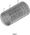
- the steel drum shown in figure 1 comprises a plurality of U-shaped sections 1 or longitudinal members 1. As shown in FIG. figure 2 each has a bottom 2 with holes 4 and two branches 3 extending radially from the bottom 2 towards the outside of the drum. Each section 1 is welded to its two adjacent sections by their branches 3, so as to form a continuous drum.
- the drum of the figure 1 has seven hoops 5 evenly distributed on the length of the drum and driven into notches 6 in the branches 3 (see figure 4 ). As shown in figure 2 , the number of the holes 4 of the bottom increases from one front side to the other of the drum.
- the figure 3 shows the branches 3A and 3B of each spar 1 of unequal length, the shorter branch of a spar being welded to the longest branch of the spar 1 neighbor.
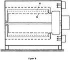
- the dryer represented at figure 5 comprises a box 11 subdivided by a partition 12 into a treatment compartment 13 and into a compartment 14 for air circulation.
- a drum 15 is rotatably mounted about its axis X being driven by a drive not shown in the compartment 13 and a fan 16 is mounted in the compartment 14. The fan sends air into the drum 15 and returns it in the compartment 14, then 13.
- the textile web to be treated rests on a thin canvas 17 stretched around the lateral surface of the drum 15 and fixed at its edges to the latter.
- the air compartment 13 is heated by one or more burners 18 in the case of the use of gas, or exchangers in the case of the use of other energy sources, such as steam or fuel oil.
- the dryer of the figure 6 differs from that of the figure 5 by the presence of a fixed internal box 19 allowing by shutters to adjust the airflow over the length of the dryer.
- the figure 7 represents a preferred dryer according to the invention.
- the dryer comprises a drum 15 rotatably mounted inside a box 11 for circulating hot air.
- the wet nonwoven to dry C enters the dryer by a detour roller 20. It rests on the surface of a canvas stretched on the rotating drum 15 during its journey inside the box 11.
- the box 11 diffuses hot air on the nonwoven. This air is heated by a burner 18 or other heating device such as exchangers.
- the hot air passes through the nonwoven to be dried and is sucked into the drum 15 by means not shown.
- the dried nonwoven D is removed from the dryer by a new detour roll 21.
- the hot air having passed through the nonwoven and having been sucked into the drum is then heated by a burner or exchanger 18 considered as the air inlet of the box, then is redirected by a fan not shown to the surface of the drum coated with the fabric and covered with nonwoven to dry.
- the figure 8 represents a U-shaped profile having circular holes in the bottom.
- An obturator 22 pierced with holes of the same size and in the same arrangement as the holes in the bottom of the U-shaped channel slides through inserts 23 into oblong holes 24 on the inside face of the U-shaped section (on the outside of the drum) so as to partially close the holes of the bottom of the U.
- Each U may have several shutters side by side so as to obtain a variable opening or closing over the entire length of each U and therefore over the entire suction width of the drum.
- the figure 9 is a sectional view of a profile 2 in U, on which is fixed a shutter 22 by screws and nuts or inserts rivklé type WWW (rivets).
Landscapes
- Engineering & Computer Science (AREA)
- Textile Engineering (AREA)
- Mechanical Engineering (AREA)
- General Engineering & Computer Science (AREA)
- Drying Of Solid Materials (AREA)
- Detail Structures Of Washing Machines And Dryers (AREA)
- Treatment Of Fiber Materials (AREA)
Claims (14)
- Trockner, umfassend ein Gehäuse (11) mit einem Heißlufteinlass (18), eine Metalltrommel (15), die drehbar um ihre Achse im Gehäuse (11) montiert ist, ein Metallgewebe (17), das um die Seitenfläche der Trommel (15) gespannt und damit drehfest ist, und Mittel (A, B) zum Durchführen einer auf dem Gewebe (17) zu trocknenden Lage (C), wobei die Seitenfläche der Trommel (15) aus U-förmigen Profilen besteht, die jeweils einen mit Löchern durchbohrten Boden (2) und zwei Schenkel (3) aufweisen, die sich radial von der Trommel (1) nach außen erstrecken, dadurch gekennzeichnet, dass jedes Profil mit seinen Schenkeln (3) an seine beiden benachbarten Profile angeschweißt ist und nur einer von ihnen oder jeder von ihnen eine Kerbe aufweist, in die ein Band eindringt.
- Trockner nach Anspruch 1, dadurch gekennzeichnet, dass das Gewebe (17) Öffnungen aufweist, deren Abmessungen im Bereich von 0,5 bis 3 mm liegen und die Trommel (15) Löcher (4) aufweist, wobei die größte Abmessung jedes Lochs (4) im Bereich von 40 bis 150 mm liegt.
- Trockner nach Anspruch 1 oder 2, dadurch gekennzeichnet, dass die Löcher (4) rechteckig sind.
- Trockner nach einem der vorstehenden Ansprüche, dadurch gekennzeichnet, dass einer der Schenkel (3) jedes Profils größer ist als der andere Schenkel (3) und das Gewebe (17) nur auf dem größten Schenkel (3) in einem Abstand vom kleinsten Schenkel (3) aufliegt.
- Trockner nach Anspruch 4, dadurch gekennzeichnet, dass die Höhe der Schenkel (3) in radialer Richtung von 30 bis 150 mm reicht.
- Trockner nach Anspruch 5, dadurch gekennzeichnet, dass die Öffnungsrate des Gewebes (17) von 25 bis 75 %, die Öffnungsrate jedes Profils vorzugsweise von 15 bis 70 % oder von 10 bis 60 % reicht.
- Trockner nach Anspruch 6, dadurch gekennzeichnet, dass der Abstand zwischen zwei benachbarten Löchern das 1,5- bis 5-fache der größten Abmessung der Löcher (4) beträgt.
- Trockner nach einem der vorstehenden Ansprüche, dadurch gekennzeichnet, dass ein Stopfen (22) der Löcher (4) verschiebbar auf dem Boden (2) jedes U-förmigen Profils montiert ist, um die Löcher (4) zumindest teilweise freizulegen oder zu schließen.
- Trockner nach Anspruch 8, dadurch gekennzeichnet, dass der Stopfen (22) an der Innenfläche des U des Bodens (2) des U-förmigen Profils montiert ist.
- Trockner nach einem der vorstehenden Ansprüche, gekennzeichnet durch eine Erhöhung der Öffnungsrate des Bodens (2) jedes U-förmigen Profils (1) von einer Vorderseite zur anderen.
- Trockner nach einem der Ansprüche 1 bis 9, gekennzeichnet durch eine Erhöhung der Öffnungsrate des Bodens (2) jedes U-förmigen Profils (1) von jeder Kante zur Mitte der Trommel.
- Trockner nach einem der Ansprüche 10 und 11, dadurch gekennzeichnet, dass die Steigerungsrate der Öffnungsrate zwischen dem 3- und 6-fachen der kleinsten Öffnungsrate liegt.
- Trockner nach einem der vorstehenden Ansprüche, dadurch gekennzeichnet, dass er nur ein Gehäuse (11) aufweist.
- Trockner nach einem der vorstehenden Ansprüche, dadurch gekennzeichnet, dass mindestens einer der Schenkel jedes Profils, und insbesondere nur einer von ihnen oder möglicherweise jeder von ihnen, eine Kerbe aufweist, in die ein Band eindringt.
Applications Claiming Priority (2)
| Application Number | Priority Date | Filing Date | Title |
|---|---|---|---|
| FR1500524A FR3033875B1 (fr) | 2015-03-17 | 2015-03-17 | Tambour metallique, notamment pour un secheur |
| PCT/EP2016/055645 WO2016146662A1 (fr) | 2015-03-17 | 2016-03-16 | Sécheur a tambour |
Publications (2)
| Publication Number | Publication Date |
|---|---|
| EP3271672A1 EP3271672A1 (de) | 2018-01-24 |
| EP3271672B1 true EP3271672B1 (de) | 2019-11-06 |
Family
ID=53040520
Family Applications (1)
| Application Number | Title | Priority Date | Filing Date |
|---|---|---|---|
| EP16711213.5A Active EP3271672B1 (de) | 2015-03-17 | 2016-03-16 | Trommeltrockner |
Country Status (6)
| Country | Link |
|---|---|
| US (1) | US10612847B2 (de) |
| EP (1) | EP3271672B1 (de) |
| CN (1) | CN107532848B (de) |
| ES (1) | ES2767650T3 (de) |
| FR (1) | FR3033875B1 (de) |
| WO (1) | WO2016146662A1 (de) |
Families Citing this family (10)
| Publication number | Priority date | Publication date | Assignee | Title |
|---|---|---|---|---|
| DE102015118596A1 (de) * | 2015-10-30 | 2017-05-04 | TRüTZSCHLER GMBH & CO. KG | Vorrichtung und Verfahren zum thermischen Behandeln einer textilen Warenbahn |
| US10533283B2 (en) * | 2017-07-18 | 2020-01-14 | Valmet, Inc. | Reduced diameter foraminous exhaust cylinder |
| CN108166163A (zh) * | 2018-03-08 | 2018-06-15 | 恒天重工股份有限公司 | 一种适用于水刺机抽吸辊筒的高透气立体托持圆网 |
| CN108796905A (zh) * | 2018-05-11 | 2018-11-13 | 河南聚力时刻环保科技有限公司 | 一种用于无纺布生产的烘干箱 |
| CN108867141B (zh) * | 2018-07-19 | 2020-12-22 | 湖南三匠人科技有限公司 | 一种穿透烘缸 |
| IT201800010377A1 (it) * | 2018-11-16 | 2020-05-16 | Sicam S R L Soc It Costruzioni Aeromeccaniche | Tamburo perforato per essiccatori ad aria passante con dispositivo distribuzione dell'aria incorporato |
| DE202019100745U1 (de) * | 2019-02-08 | 2020-05-11 | Autefa Solutions Germany Gmbh | Trocknungseinrichtung |
| CN112066673B (zh) * | 2020-09-19 | 2022-04-08 | 东莞市爱克斯曼机械有限公司 | 一种圆网烘箱 |
| EP4083553A1 (de) | 2021-04-30 | 2022-11-02 | SICAM - S.R.L. Societa' Italiana Costruzioni Aeromeccaniche | Perforierte trommel für durchlufttrockner |
| CN114136071A (zh) * | 2021-11-16 | 2022-03-04 | 东莞长联智能科技有限公司 | 热风循环型滚筒式烘干设备 |
Family Cites Families (12)
| Publication number | Priority date | Publication date | Assignee | Title |
|---|---|---|---|---|
| GB1151709A (en) * | 1965-10-14 | 1969-05-14 | Beloit Corp | Improvements in or relating to Drying Webs |
| DE1635350A1 (de) * | 1967-01-07 | 1971-03-11 | Vepa Ag | Verfahren und Vorrichtung zum Trocknen von bahn- und bandfoermigem Textilgut |
| US4542596A (en) * | 1984-07-19 | 1985-09-24 | Honeycomb Systems, Inc. | Honeycomb grilled conduit |
| DE68903255T2 (de) * | 1988-08-12 | 1993-05-19 | Lamort E & M | Sieb zur reinigung und klassifizierung von papierstoffbrei. |
| DE4239640A1 (en) * | 1992-11-26 | 1993-07-01 | Voith Gmbh J M | Paper-making roller - has channels from U=shaped rails fitted to the roller mantle |
| US5575080A (en) * | 1994-06-28 | 1996-11-19 | Fleissner Gmbh & Co., Kg | Device for the continuous-flow treatment of textile material or like fiber containg material |
| US7040038B1 (en) * | 1998-09-02 | 2006-05-09 | Metso Paper Usa, Inc. | Apparatus for processing permeable or semi-permeable webs |
| US6131308A (en) * | 1999-09-10 | 2000-10-17 | Ingenieurgemeinschaft Wsp, Prof. Dr.-Ing C Kramer, Prof. Dipl.-Ing H.J. Gerhardt M.S. | Apparatus for levitational guidance of web material |
| DE10001535A1 (de) * | 2000-01-14 | 2001-07-19 | Fleissner Maschf Gmbh Co | Vorrichtung vorzugsweise zum hydrodynamischen Vernadeln von z. B. Vliesen, Tissue oder Papier mit einer Blechtrommel als Unterstützungselement für das Gut |
| DE10253352A1 (de) * | 2002-11-14 | 2004-05-27 | Fleissner Gmbh & Co. Maschinenfabrik | Vorrichtung zum durchströmenden oder beaufschlagenden Behandeln von bahnförmiger Ware |
| DE102011113835A1 (de) * | 2011-09-21 | 2013-03-21 | Trützschler Nonwovens Gmbh | Vorrichtung zum Behandeln von einem Gut, insbesondere zum Trocknen eines vorzugsweise bahnförmigen Guts |
| DE202013102203U1 (de) * | 2012-08-23 | 2013-06-06 | Trützschler GmbH & Co Kommanditgesellschaft | Vorrichtung zur hydrodynamischen Verfestigung von Vliesen, Geweben oder Gewirken |
-
2015
- 2015-03-17 FR FR1500524A patent/FR3033875B1/fr active Active
-
2016
- 2016-03-16 ES ES16711213T patent/ES2767650T3/es active Active
- 2016-03-16 WO PCT/EP2016/055645 patent/WO2016146662A1/fr not_active Ceased
- 2016-03-16 CN CN201680014976.1A patent/CN107532848B/zh active Active
- 2016-03-16 EP EP16711213.5A patent/EP3271672B1/de active Active
- 2016-03-16 US US15/558,604 patent/US10612847B2/en active Active
Non-Patent Citations (1)
| Title |
|---|
| None * |
Also Published As
| Publication number | Publication date |
|---|---|
| CN107532848B (zh) | 2020-04-10 |
| ES2767650T3 (es) | 2020-06-18 |
| WO2016146662A1 (fr) | 2016-09-22 |
| CN107532848A (zh) | 2018-01-02 |
| US10612847B2 (en) | 2020-04-07 |
| EP3271672A1 (de) | 2018-01-24 |
| FR3033875B1 (fr) | 2021-06-18 |
| FR3033875A1 (fr) | 2016-09-23 |
| US20180080712A1 (en) | 2018-03-22 |
Similar Documents
| Publication | Publication Date | Title |
|---|---|---|
| EP3271672B1 (de) | Trommeltrockner | |
| FR2549505A1 (fr) | Sechoir pour produits textiles | |
| CN111089470B (zh) | 一种无纺布生产加工烘干定型处理工艺 | |
| EP0066661A1 (de) | Vorrichtung zum Trocknen von Bahnen durch Heissluft bei gleichzeitiger Unterstützung der Bahn, vorzugsweise von Papierbahnen aus Druckmaschinen | |
| FR2563327A1 (fr) | Installation de sechage de produits par echange de chaleur avec un fluide de sechage | |
| US11655590B1 (en) | Through-air apparatus with cooling system | |
| EP3012565A1 (de) | Trockentunnel für keramische produkte | |
| FR2562220A1 (fr) | Sechoir a air chaud pour matieres en vrac, en particulier matieres fibreuses textiles | |
| FR2465975A1 (fr) | Sechoir continu pour cereales humides | |
| BE491461A (de) | ||
| FR2752613A1 (fr) | Dispositif pour l'echange de chaleur et de matiere entre des milieux liquides et gazeux | |
| BE508275A (de) | ||
| FR2518724A1 (fr) | Sechoir notamment pour tricots | |
| FR3077505A1 (fr) | Goupille et distributeur de liquide muni de goupilles | |
| BE401889A (de) | ||
| BE462483A (de) | ||
| BE446586A (de) | ||
| BE481808A (de) | ||
| BE657075A (de) | ||
| CN110839910A (zh) | 一种胡萝卜加工系统 | |
| EP0082076A2 (de) | Vorrichtung zum Trocknen und Fixieren von gewebten oder gewirkten Warenstücken | |
| CH288695A (fr) | Installation pour le traitement thermique de finissage d'une matière textile. | |
| BE559861A (de) | ||
| FR2571157A1 (fr) | Dispositif de sechage pour pellicule photographique en bande ou en feuille | |
| BE543874A (de) |
Legal Events
| Date | Code | Title | Description |
|---|---|---|---|
| STAA | Information on the status of an ep patent application or granted ep patent |
Free format text: STATUS: THE INTERNATIONAL PUBLICATION HAS BEEN MADE |
|
| PUAI | Public reference made under article 153(3) epc to a published international application that has entered the european phase |
Free format text: ORIGINAL CODE: 0009012 |
|
| STAA | Information on the status of an ep patent application or granted ep patent |
Free format text: STATUS: REQUEST FOR EXAMINATION WAS MADE |
|
| 17P | Request for examination filed |
Effective date: 20171017 |
|
| AK | Designated contracting states |
Kind code of ref document: A1 Designated state(s): AL AT BE BG CH CY CZ DE DK EE ES FI FR GB GR HR HU IE IS IT LI LT LU LV MC MK MT NL NO PL PT RO RS SE SI SK SM TR |
|
| AX | Request for extension of the european patent |
Extension state: BA ME |
|
| DAV | Request for validation of the european patent (deleted) | ||
| DAX | Request for extension of the european patent (deleted) | ||
| TPAC | Observations filed by third parties |
Free format text: ORIGINAL CODE: EPIDOSNTIPA |
|
| STAA | Information on the status of an ep patent application or granted ep patent |
Free format text: STATUS: EXAMINATION IS IN PROGRESS |
|
| 17Q | First examination report despatched |
Effective date: 20180924 |
|
| GRAP | Despatch of communication of intention to grant a patent |
Free format text: ORIGINAL CODE: EPIDOSNIGR1 |
|
| STAA | Information on the status of an ep patent application or granted ep patent |
Free format text: STATUS: GRANT OF PATENT IS INTENDED |
|
| INTG | Intention to grant announced |
Effective date: 20190619 |
|
| GRAS | Grant fee paid |
Free format text: ORIGINAL CODE: EPIDOSNIGR3 |
|
| GRAA | (expected) grant |
Free format text: ORIGINAL CODE: 0009210 |
|
| STAA | Information on the status of an ep patent application or granted ep patent |
Free format text: STATUS: THE PATENT HAS BEEN GRANTED |
|
| AK | Designated contracting states |
Kind code of ref document: B1 Designated state(s): AL AT BE BG CH CY CZ DE DK EE ES FI FR GB GR HR HU IE IS IT LI LT LU LV MC MK MT NL NO PL PT RO RS SE SI SK SM TR |
|
| REG | Reference to a national code |
Ref country code: GB Ref legal event code: FG4D Free format text: NOT ENGLISH |
|
| REG | Reference to a national code |
Ref country code: CH Ref legal event code: EP Ref country code: AT Ref legal event code: REF Ref document number: 1199304 Country of ref document: AT Kind code of ref document: T Effective date: 20191115 |
|
| REG | Reference to a national code |
Ref country code: IE Ref legal event code: FG4D Free format text: LANGUAGE OF EP DOCUMENT: FRENCH |
|
| REG | Reference to a national code |
Ref country code: DE Ref legal event code: R096 Ref document number: 602016023735 Country of ref document: DE |
|
| REG | Reference to a national code |
Ref country code: CH Ref legal event code: NV Representative=s name: E. BLUM AND CO. AG PATENT- UND MARKENANWAELTE , CH |
|
| REG | Reference to a national code |
Ref country code: NL Ref legal event code: MP Effective date: 20191106 |
|
| REG | Reference to a national code |
Ref country code: LT Ref legal event code: MG4D |
|
| PG25 | Lapsed in a contracting state [announced via postgrant information from national office to epo] |
Ref country code: FI Free format text: LAPSE BECAUSE OF FAILURE TO SUBMIT A TRANSLATION OF THE DESCRIPTION OR TO PAY THE FEE WITHIN THE PRESCRIBED TIME-LIMIT Effective date: 20191106 Ref country code: NO Free format text: LAPSE BECAUSE OF FAILURE TO SUBMIT A TRANSLATION OF THE DESCRIPTION OR TO PAY THE FEE WITHIN THE PRESCRIBED TIME-LIMIT Effective date: 20200206 Ref country code: GR Free format text: LAPSE BECAUSE OF FAILURE TO SUBMIT A TRANSLATION OF THE DESCRIPTION OR TO PAY THE FEE WITHIN THE PRESCRIBED TIME-LIMIT Effective date: 20200207 Ref country code: PL Free format text: LAPSE BECAUSE OF FAILURE TO SUBMIT A TRANSLATION OF THE DESCRIPTION OR TO PAY THE FEE WITHIN THE PRESCRIBED TIME-LIMIT Effective date: 20191106 Ref country code: SE Free format text: LAPSE BECAUSE OF FAILURE TO SUBMIT A TRANSLATION OF THE DESCRIPTION OR TO PAY THE FEE WITHIN THE PRESCRIBED TIME-LIMIT Effective date: 20191106 Ref country code: LV Free format text: LAPSE BECAUSE OF FAILURE TO SUBMIT A TRANSLATION OF THE DESCRIPTION OR TO PAY THE FEE WITHIN THE PRESCRIBED TIME-LIMIT Effective date: 20191106 Ref country code: BG Free format text: LAPSE BECAUSE OF FAILURE TO SUBMIT A TRANSLATION OF THE DESCRIPTION OR TO PAY THE FEE WITHIN THE PRESCRIBED TIME-LIMIT Effective date: 20200206 Ref country code: PT Free format text: LAPSE BECAUSE OF FAILURE TO SUBMIT A TRANSLATION OF THE DESCRIPTION OR TO PAY THE FEE WITHIN THE PRESCRIBED TIME-LIMIT Effective date: 20200306 Ref country code: LT Free format text: LAPSE BECAUSE OF FAILURE TO SUBMIT A TRANSLATION OF THE DESCRIPTION OR TO PAY THE FEE WITHIN THE PRESCRIBED TIME-LIMIT Effective date: 20191106 Ref country code: NL Free format text: LAPSE BECAUSE OF FAILURE TO SUBMIT A TRANSLATION OF THE DESCRIPTION OR TO PAY THE FEE WITHIN THE PRESCRIBED TIME-LIMIT Effective date: 20191106 |
|
| PG25 | Lapsed in a contracting state [announced via postgrant information from national office to epo] |
Ref country code: IS Free format text: LAPSE BECAUSE OF FAILURE TO SUBMIT A TRANSLATION OF THE DESCRIPTION OR TO PAY THE FEE WITHIN THE PRESCRIBED TIME-LIMIT Effective date: 20200306 Ref country code: HR Free format text: LAPSE BECAUSE OF FAILURE TO SUBMIT A TRANSLATION OF THE DESCRIPTION OR TO PAY THE FEE WITHIN THE PRESCRIBED TIME-LIMIT Effective date: 20191106 Ref country code: RS Free format text: LAPSE BECAUSE OF FAILURE TO SUBMIT A TRANSLATION OF THE DESCRIPTION OR TO PAY THE FEE WITHIN THE PRESCRIBED TIME-LIMIT Effective date: 20191106 |
|
| REG | Reference to a national code |
Ref country code: ES Ref legal event code: FG2A Ref document number: 2767650 Country of ref document: ES Kind code of ref document: T3 Effective date: 20200618 |
|
| PG25 | Lapsed in a contracting state [announced via postgrant information from national office to epo] |
Ref country code: AL Free format text: LAPSE BECAUSE OF FAILURE TO SUBMIT A TRANSLATION OF THE DESCRIPTION OR TO PAY THE FEE WITHIN THE PRESCRIBED TIME-LIMIT Effective date: 20191106 |
|
| PG25 | Lapsed in a contracting state [announced via postgrant information from national office to epo] |
Ref country code: DK Free format text: LAPSE BECAUSE OF FAILURE TO SUBMIT A TRANSLATION OF THE DESCRIPTION OR TO PAY THE FEE WITHIN THE PRESCRIBED TIME-LIMIT Effective date: 20191106 Ref country code: EE Free format text: LAPSE BECAUSE OF FAILURE TO SUBMIT A TRANSLATION OF THE DESCRIPTION OR TO PAY THE FEE WITHIN THE PRESCRIBED TIME-LIMIT Effective date: 20191106 Ref country code: RO Free format text: LAPSE BECAUSE OF FAILURE TO SUBMIT A TRANSLATION OF THE DESCRIPTION OR TO PAY THE FEE WITHIN THE PRESCRIBED TIME-LIMIT Effective date: 20191106 Ref country code: CZ Free format text: LAPSE BECAUSE OF FAILURE TO SUBMIT A TRANSLATION OF THE DESCRIPTION OR TO PAY THE FEE WITHIN THE PRESCRIBED TIME-LIMIT Effective date: 20191106 |
|
| REG | Reference to a national code |
Ref country code: DE Ref legal event code: R097 Ref document number: 602016023735 Country of ref document: DE |
|
| PG25 | Lapsed in a contracting state [announced via postgrant information from national office to epo] |
Ref country code: SM Free format text: LAPSE BECAUSE OF FAILURE TO SUBMIT A TRANSLATION OF THE DESCRIPTION OR TO PAY THE FEE WITHIN THE PRESCRIBED TIME-LIMIT Effective date: 20191106 Ref country code: SK Free format text: LAPSE BECAUSE OF FAILURE TO SUBMIT A TRANSLATION OF THE DESCRIPTION OR TO PAY THE FEE WITHIN THE PRESCRIBED TIME-LIMIT Effective date: 20191106 |
|
| PLBE | No opposition filed within time limit |
Free format text: ORIGINAL CODE: 0009261 |
|
| STAA | Information on the status of an ep patent application or granted ep patent |
Free format text: STATUS: NO OPPOSITION FILED WITHIN TIME LIMIT |
|
| 26N | No opposition filed |
Effective date: 20200807 |
|
| PG25 | Lapsed in a contracting state [announced via postgrant information from national office to epo] |
Ref country code: MC Free format text: LAPSE BECAUSE OF FAILURE TO SUBMIT A TRANSLATION OF THE DESCRIPTION OR TO PAY THE FEE WITHIN THE PRESCRIBED TIME-LIMIT Effective date: 20191106 |
|
| PG25 | Lapsed in a contracting state [announced via postgrant information from national office to epo] |
Ref country code: SI Free format text: LAPSE BECAUSE OF FAILURE TO SUBMIT A TRANSLATION OF THE DESCRIPTION OR TO PAY THE FEE WITHIN THE PRESCRIBED TIME-LIMIT Effective date: 20191106 |
|
| REG | Reference to a national code |
Ref country code: BE Ref legal event code: MM Effective date: 20200331 |
|
| PG25 | Lapsed in a contracting state [announced via postgrant information from national office to epo] |
Ref country code: LU Free format text: LAPSE BECAUSE OF NON-PAYMENT OF DUE FEES Effective date: 20200316 |
|
| PG25 | Lapsed in a contracting state [announced via postgrant information from national office to epo] |
Ref country code: IE Free format text: LAPSE BECAUSE OF NON-PAYMENT OF DUE FEES Effective date: 20200316 |
|
| PG25 | Lapsed in a contracting state [announced via postgrant information from national office to epo] |
Ref country code: BE Free format text: LAPSE BECAUSE OF NON-PAYMENT OF DUE FEES Effective date: 20200331 |
|
| GBPC | Gb: european patent ceased through non-payment of renewal fee |
Effective date: 20200316 |
|
| PG25 | Lapsed in a contracting state [announced via postgrant information from national office to epo] |
Ref country code: GB Free format text: LAPSE BECAUSE OF NON-PAYMENT OF DUE FEES Effective date: 20200316 |
|
| PG25 | Lapsed in a contracting state [announced via postgrant information from national office to epo] |
Ref country code: MT Free format text: LAPSE BECAUSE OF FAILURE TO SUBMIT A TRANSLATION OF THE DESCRIPTION OR TO PAY THE FEE WITHIN THE PRESCRIBED TIME-LIMIT Effective date: 20191106 Ref country code: CY Free format text: LAPSE BECAUSE OF FAILURE TO SUBMIT A TRANSLATION OF THE DESCRIPTION OR TO PAY THE FEE WITHIN THE PRESCRIBED TIME-LIMIT Effective date: 20191106 |
|
| PG25 | Lapsed in a contracting state [announced via postgrant information from national office to epo] |
Ref country code: MK Free format text: LAPSE BECAUSE OF FAILURE TO SUBMIT A TRANSLATION OF THE DESCRIPTION OR TO PAY THE FEE WITHIN THE PRESCRIBED TIME-LIMIT Effective date: 20191106 |
|
| REG | Reference to a national code |
Ref country code: AT Ref legal event code: UEP Ref document number: 1199304 Country of ref document: AT Kind code of ref document: T Effective date: 20191106 |
|
| PGFP | Annual fee paid to national office [announced via postgrant information from national office to epo] |
Ref country code: DE Payment date: 20250319 Year of fee payment: 10 |
|
| PGFP | Annual fee paid to national office [announced via postgrant information from national office to epo] |
Ref country code: AT Payment date: 20250320 Year of fee payment: 10 |
|
| PGFP | Annual fee paid to national office [announced via postgrant information from national office to epo] |
Ref country code: FR Payment date: 20250325 Year of fee payment: 10 |
|
| PGFP | Annual fee paid to national office [announced via postgrant information from national office to epo] |
Ref country code: IT Payment date: 20250325 Year of fee payment: 10 |
|
| PGFP | Annual fee paid to national office [announced via postgrant information from national office to epo] |
Ref country code: TR Payment date: 20250310 Year of fee payment: 10 |
|
| PGFP | Annual fee paid to national office [announced via postgrant information from national office to epo] |
Ref country code: ES Payment date: 20250429 Year of fee payment: 10 |
|
| PGFP | Annual fee paid to national office [announced via postgrant information from national office to epo] |
Ref country code: CH Payment date: 20250401 Year of fee payment: 10 |