EP3267905B1 - Magnetische anastomosevorrichtung mit variierender magnetkraft bei einem abstand - Google Patents
Magnetische anastomosevorrichtung mit variierender magnetkraft bei einem abstand Download PDFInfo
- Publication number
- EP3267905B1 EP3267905B1 EP16711492.5A EP16711492A EP3267905B1 EP 3267905 B1 EP3267905 B1 EP 3267905B1 EP 16711492 A EP16711492 A EP 16711492A EP 3267905 B1 EP3267905 B1 EP 3267905B1
- Authority
- EP
- European Patent Office
- Prior art keywords
- magnetic
- polygon
- segments
- segment
- magnetic segments
- Prior art date
- Legal status (The legal status is an assumption and is not a legal conclusion. Google has not performed a legal analysis and makes no representation as to the accuracy of the status listed.)
- Active
Links
Images


Classifications
-
- A—HUMAN NECESSITIES
- A61—MEDICAL OR VETERINARY SCIENCE; HYGIENE
- A61B—DIAGNOSIS; SURGERY; IDENTIFICATION
- A61B17/00—Surgical instruments, devices or methods
- A61B17/11—Surgical instruments, devices or methods for performing anastomosis; Buttons for anastomosis
- A61B17/1114—Surgical instruments, devices or methods for performing anastomosis; Buttons for anastomosis of the digestive tract, e.g. bowels or oesophagus
-
- A—HUMAN NECESSITIES
- A61—MEDICAL OR VETERINARY SCIENCE; HYGIENE
- A61B—DIAGNOSIS; SURGERY; IDENTIFICATION
- A61B17/00—Surgical instruments, devices or methods
- A61B17/12—Surgical instruments, devices or methods for ligaturing or otherwise compressing tubular parts of the body, e.g. blood vessels or umbilical cord
- A61B17/12022—Occluding by internal devices, e.g. balloons or releasable wires
- A61B17/12131—Occluding by internal devices, e.g. balloons or releasable wires characterised by the type of occluding device
- A61B17/12163—Occluding by internal devices, e.g. balloons or releasable wires characterised by the type of occluding device having a string of elements connected to each other
-
- A—HUMAN NECESSITIES
- A61—MEDICAL OR VETERINARY SCIENCE; HYGIENE
- A61B—DIAGNOSIS; SURGERY; IDENTIFICATION
- A61B17/00—Surgical instruments, devices or methods
- A61B2017/00831—Material properties
- A61B2017/00876—Material properties magnetic
-
- A—HUMAN NECESSITIES
- A61—MEDICAL OR VETERINARY SCIENCE; HYGIENE
- A61B—DIAGNOSIS; SURGERY; IDENTIFICATION
- A61B17/00—Surgical instruments, devices or methods
- A61B17/11—Surgical instruments, devices or methods for performing anastomosis; Buttons for anastomosis
- A61B17/1114—Surgical instruments, devices or methods for performing anastomosis; Buttons for anastomosis of the digestive tract, e.g. bowels or oesophagus
- A61B2017/1117—Surgical instruments, devices or methods for performing anastomosis; Buttons for anastomosis of the digestive tract, e.g. bowels or oesophagus adapted for discharge after necrotisation, e.g. by evacuation, expulsion or excretion
-
- A—HUMAN NECESSITIES
- A61—MEDICAL OR VETERINARY SCIENCE; HYGIENE
- A61B—DIAGNOSIS; SURGERY; IDENTIFICATION
- A61B17/00—Surgical instruments, devices or methods
- A61B17/11—Surgical instruments, devices or methods for performing anastomosis; Buttons for anastomosis
- A61B2017/1139—Side-to-side connections, e.g. shunt or X-connections
Definitions
- the invention relates to deployable magnetic compression devices and their use for creating anastomoses, e.g., in the gastrointestinal tract.
- the devices are especially useful for minimally-invasive delivery, e.g., using endoscopic and/or laparoscopic techniques.
- Bypasses of the gastroenterological (GI), cardiovascular, or urological systems are typically formed by cutting holes in tissues at two locations and joining the holes with sutures or staples.
- a bypass is typically placed to route fluids (e.g., blood, nutrients) between healthier portions of the system, while bypassing diseases or malfunctioning tissues.
- the procedure is typically invasive, and subjects a patient to risks such as bleeding, infection, pain, and adverse reaction to anesthesia.
- a bypass created with sutures or staples can be complicated by post-operative leaks and adhesions. Leaks may result in infection or sepsis, while adhesions can result in complications such as bowel strangulation and obstruction.
- Traditional bypass procedures can be completed with an endoscope, laparoscope, or robot, it can be time consuming to join the holes cut into the tissues. Furthermore, such procedures require specialized expertise and equipment that is not available at many surgical facilities.
- surgeons can use mechanical couplings or magnets to create a compressive anastomosis between tissues.
- compressive couplings or paired magnets can be delivered to tissues to be joined. Because of the strong compression, the tissue trapped between the couplings or magnets is cut off from its blood supply. Under these conditions, the tissue becomes necrotic and degenerates, and at the same time, new tissue grows around points of compression, e.g., on the edges of the coupling. With time, the coupling can be removed, leaving a healed anastomosis between the tissues.
- the difficulty of placing the magnets or couplings limits the locations that compressive anastomosis can be used.
- the magnets or couplings have to be delivered as two separate assemblies, requiring either an open surgical field or a bulky delivery device.
- existing magnetic compression devices are limited to structures small enough to be deployed with a delivery conduit e.g., an endoscopic instrument channel or laparoscopic port. When these smaller structures are used, the formed anastomosis is small and suffers from short-term patency.
- the invention provides a self-opening magnetic compression anastomosis device as set out in claim 1.
- Such devices and techniques facilitate faster and less-expensive treatments for chronic diseases such as obesity and diabetes.
- Such techniques also reduce the time and pain associated with palliative treatments for diseases such as cancers, such as stomach or colon cancer.
- the invention provides multiple configurations of magnetic devices comprising an assembly of magnetic segments that can be used to create anastomoses in a subject.
- the devices are self-opening, and designed to be delivered via a trocar using laparoscopic techniques.
- the self-opening devices are constructed from an assembly of magnetic segments including connection members between adjacent segments. Some of the connection members serve as hinges so as to allow adjacent magnetic segments to move relative to one another, particularly when the device transitions between delivery and deployed configurations, while one or more of the connection members serve as a spring or other device for directing the magnetic segments to open to form a polygon.
- the device includes an assembly including a first pair of adjacent magnetic segments movably coupled together with a first hinge connection member and a second pair of adjacent magnetic segments movably coupled together with a second hinge connection member.
- the assembly includes a delivery configuration in which the magnetic segments are aligned in two rows, the two rows being joined by the first and second hinge connection members or one or more polygon-opening connection members coupling the first and second pairs of magnetic segments to one another.
- the assembly further includes a deployed configuration in which the magnetic segments form an open polygon based, at least in part, on a force provided by the polygon-opening connection members and, optionally, at least one of the first and second hinge connection members.
- at least one of the first and second hinge connection members may include a spring, so as to direct the magnetic segments to open upon deployment.
- the devices of the invention include a variety of configurations constructed from magnetic segments. Each magnetic segment has a north and a south magnetic pole.
- a device of the invention may include, for example, four segments allowing the deployed device to take the shape of a square. Alternatively, the device may include eight segments, allowing the device to take the shape of an octagon. Other arrangements are also feasible, including hexagons, decagons, dodecagons, tetradecagons, hexadecagons, etc.
- the polygon has a top and a bottom, and the magnetic segments can be arranged such that all or some of the north poles of the magnetic segments are arranged toward the top of the polygon.
- the inventors have discovered that for a given number of magnetic segments in a pair of devices, e.g., eight segments, different arrangements of north and south poles will result in different magnetic fields at a distance for the paired devices. However, the different arrangements will experience approximately the same attractive magnetic force when the devices are in close proximity, i.e., touching. This feature can be used to achieve variable magnetic force between paired devices during a surgical procedure in which an anastomosis is to be created.
- the surgeon may select a pair of devices in which all of the north poles are arranged in the same direction.
- the surgeon may select a pair of devices in which the arrangement of the north and south poles are alternating for each magnetic element.
- one of the devices may include hinges at first and second ends of the device and polygon-opening members that direct the magnetic segments to open into a polygon upon deployment.
- This device can be delivered, e.g., via a trocar in a side-by-side delivery configuration.
- the other device may be constructed from magnetic segments coupled together in a linear arrangement with polygon-closing members that direct the device to close and form a polygon upon deployment. This device can be delivered via the working channel of an endoscope in a linear configuration.
- the kit may include a plurality of devices having the same delivery/deployment configuration but having different magnetic polar arrangements, or the kit may include a plurality of devices with the same magnetic polar arrangement but different delivery/deployment configurations. Other combinations of delivery/deployment configuration and magnetic polar arrangement are also possible.
- the invention provides a self-opening magnetic compression anastomosis device.
- the device includes an assembly of at least four magnetic segments coupled end-to-end to form a polygon having an out-of-plane axis, wherein each magnetic segment has a north magnetic pole and a south magnetic pole.
- the assembly includes a first pair of magnetic segments coupled together with a first connection member and a second pair of magnetic segments coupled together with a second connection member.
- the assembly includes a delivery configuration in which the magnetic segments are aligned in two rows, the two rows being joined by the first and second connection members or one or more additional connection members coupling the first and second pairs of magnetic segments to one another, and a deployed configuration in which the magnetic segments form an open polygon based, at least in part, on a force provided by at least one of the first and second connection members or the additional connection members.
- the first pair of magnetic segments have their north poles aligned relative to one another with respect to the out-of-plane axis and the second pair of magnetic segments have their north poles aligned relative to one another with respect to the out-of-plane axis.
- the north poles of the first pair of magnetic segments are aligned with the north poles of the second pair of magnetic segments with respect to the out-of-plane axis.
- north poles of the first pair magnetic segments are anti-aligned with the north poles of the second pair of magnetic segments with respect to the out-of-plane axis.
- the first pair of magnetic segments have their north poles anti-aligned relative to one another with respect to the out-of-plane axis and the second pair of magnetic segments have their north poles anti-aligned relative to one another with respect to the out-of-plane axis.
- the north magnetic poles of the magnetic segments alternate in orientation with respect to a top and a bottom of the polygon from segment to segment.
- the assembly includes four magnetic segments.
- the polygon has a top and a bottom, and two magnetic segments have their north magnetic poles arranged toward the top of the polygon and two other magnetic segments have their north magnetic poles arranged toward the bottom of the polygon.
- the north magnetic poles of the magnetic segments alternate in orientation with respect to the top and bottom of the polygon from segment to segment.
- the assembly includes a first magnetic segment, a second magnetic segment immediately adjacent to the first magnetic segment, a third magnetic segment immediately adjacent to the second magnetic segment, and a fourth magnetic segment immediately adjacent to the third and first magnetic segments.
- the north magnetic poles of the first and third magnetic segments are arranged toward the top of the polygon and the north magnetic poles of the second and fourth magnetic segments are arranged toward the bottom of the polygon.
- the assembly includes eight magnetic segments such that the assembly further includes a third pair of magnetic segments coupled together with a first of the polygon-opening connection members and a fourth pair of magnetic segments coupled together with a second of the polygon-opening connection members.
- the magnetic segments are aligned in two rows, the two rows being joined by the first and second hinge connection members, the third pair of magnetic segments (810) is in the first row and coupled to the first and second pairs of magnetic segments (810) via third and fourth polygon-opening connection members (850), and the fourth pair of magnetic segments (810) is in the second row and coupled to the first and second pairs of magnetic segments (810) via fifth and sixth polygon-opening connection members (850).
- the magnetic segments form an open polygon based, at least in part, on a force provided by at least one of the polygon-opening connection members.
- the polygon When including eight magnetic segments, the polygon has a top and a bottom, and four magnetic segments have their north magnetic poles arranged toward the top of the polygon and four other magnetic segments have their north magnetic poles arranged toward the bottom of the polygon.
- the north magnetic poles of the magnetic segments alternate in orientation with respect to the top and bottom of the polygon from segment to segment.
- the assembly includes a first magnetic segment, a second magnetic segment immediately adjacent to the first magnetic segment, a third magnetic segment immediately adjacent to the second magnetic segment, a fourth magnetic segment immediately adjacent to the third magnetic segment, a fifth magnetic segment immediately adjacent to the fourth magnetic segment, a sixth magnetic segment immediately adjacent to the fifth magnetic segment, a seventh magnetic segment immediately adjacent to the sixth magnetic segment, and an eighth magnetic segment immediately adjacent to the first and seventh magnetic segments.
- the north magnetic poles of the first, third, fifth, and seventh magnetic segments are arranged toward the top of the polygon and the north magnetic poles of the second, fourth, sixth, and eighth magnetic segments are arranged toward the bottom of the polygon.
- the assembly includes eight magnetic segments
- four adjacent magnetic segments have their north magnetic poles arranged toward the top of the polygon and four other adjacent magnetic segments have their north magnetic poles arranged toward the bottom of the polygon.
- the eight magnetic segments have their north magnetic poles aligned in the same direction with respect to the out-of-plane axis.
- connection members includes a stainless steel, plastic, or nitinol material. In some embodiments, one or more of the connection members includes a spring. In some embodiments, one or more of the connection members includes a hinge. In some embodiments, one or more of the connection members is coupled to the exterior of the polygon. The one or more of the connection members may be an exoskeleton.
- the polygon may include at least one of a square, hexagon, octagon, decagon, dodecagon, tetradecagon, hexadecagon, octodecagon, and icosagon.
- the assembly of magnetic segments When in the delivery configuration, the assembly of magnetic segments is sized to fit within a working channel of an access device and to be delivered to an anatomical structure within a patient.
- the assembly is configured to spontaneously convert from the delivery configuration to the deployed configuration once expelled from the working channel of the access device.
- the access device may include one of an endoscope, a laparoscope, a trocar, and a cannula.
- the assembly of magnetic segments is configured to be coupled to a guide element and configured to translate along a length of the guide element when transitioning from the delivery configuration to the deployed configuration.
- the guide element may include a guidewire configured to fit within the working channel of the access device and coupled to the self-opening magnetic compression anastomosis device, wherein the assembly of magnetic segments is configured to translate along a length of the guidewire when transitioning from the delivery configuration to the deployed configuration.
- the invention includes self-opening polygonal magnetic devices that couple to each other with substantial compressive magnetic force.
- the invention makes it possible to create surgical anastomoses in tissue quickly with minimally-invasive techniques such as endoscopy and laparoscopy. Once the devices are placed and mated, the compressive forces cause the vasculature of the tissue to collapse and fluids to extrude from the tissues, reducing the distance between the devices and increasing the magnetic attraction. With time, the coupled devices eventually mate completely, form an opening, and fall away from the tissue, leaving an anastomosis.
- the magnetic devices can, thus, be used to create surgical-quality anastomosis without the need to create an open surgical field.
- the devices of the invention generally comprise magnetic segments that can assume a delivery conformation and a deployed configuration.
- the delivery configuration is typically linear so that the device can be delivered to a tissue via a laparoscopic "keyhole" incision or with delivery via a natural pathway, e.g., via the esophagus, with an endoscope or similar device.
- the delivery conformation is typically somewhat flexible so that the device can be guided through various curves in the body.
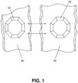
- two devices 10 and 20 are brought to opposite sides of tissues 30 and 40, in which an anastomosis is to be formed.
- the devices 10 and 20 mate and bring the tissues 30 and 40 together.
- an anastomosis of the size and shape of the devices 10 and 20 will form and the devices will fall away from the tissue.
- a surgeon may create an anastomosis, by making an incision in the tissues 30 and 40 circumscribed by the devices.
- a surgeon may first cut into the tissue, e.g., tissue 30, and then deliver the device 10 around the incision and then couple the second device 20 to the first device so that the devices 10 and 20 circumscribes the incision.
- tissue e.g., tissue 30
- the mating device 20 may be delivered in the same way, e.g., through an incision, or the mating device 20 can be delivered via a different surgical route, e.g., via an endoscope.
- the position of the two devices 10 and 20 can be visualized directly, e.g., using an endoscopic or laparoscopic camera.
- the two devices 10 and 20 can be monitored with ultrasound or another medical imaging technique, such as fluoroscopy.
- the visualization will be provided with the delivery device.
- the visualization will be achieved with a separate device.
- Other techniques, known in the art, such as dyes, contrast, and gas delivery may also be used to assist visualization of the mating devices.
- the design of the devices 10 and 20 can be customized depending upon the surgical techniques that will be used and the specific needs of the patient.
- the design specifications may include: required capture range, desired effective inner and outer diameters of the magnetic device (e.g., as defined by the desired anastomosis size and instrument passage), thickness of the target tissue, and the inner diameter of the guiding channel and the smallest radius of curvature to which the guiding channel may be bent and through which the magnets must pass.
- corresponding magnetic device designs can be determined, such as polygon-side-count and length, and the maximum lateral dimensions of the flexible linear magnetic structure that will be deployed through the delivery instrument.
- the arrangements of the magnetic segments that make up the device may be altered to customize the amount of force between the devices 10 and 20 at a distance, e.g., at 1 cm or further apart.
- anastomoses may be formed between the stomach, small intestine, gall bladder, and colon, as shown in FIG. 2 .
- Such techniques can be used for management of disease, such as obesity and diabetes, or such techniques can be used to improve function in the wake of disease, such as cancer.
- Such techniques can also be used for repair, for example, to connect portions of healthy colon after a portion of diseased colon has been removed. Such procedures can be accomplished endoscopically, laparoscopically, with an open surgical field, or with some combination of these techniques.
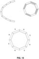
- a device of the invention generally, includes a plurality of magnetic segments that assume the shape of a polygon once deployed in a patient.
- the magnetic segments are typically formed from rare earth magnets.
- the magnetic segments may be mitered.
- the magnetic segments may be coated with gold or plastic to improve their performance.
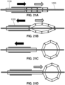
- a general depiction of an octagonal device is shown in FIG. 3 , however it is to be understood that a variety of deployed shapes are feasible using the same construction, such as squares, hexagons, decagons, dodecagons, tetradecagons, hexadecagons, octodecagons, and icosagons. As shown in FIG.
- each magnetic segment of the device has at least at least two poles, north “N” and south “S,” with the poles oriented normal to the face of the polygon.
- N north
- S south
- the north magnetic poles of the segments of the application are sometimes cross-hatched, while the south magnetic poles are solid (or not cross-hatched).
- an out of plane axis can be defined that runs through the center of the polygon and normal to the face of the polygon, defining a "TOP” and a "BOTTOM” of the device. (It is understood that "TOP” and “BOTTOM” are arbitrary, but correspond to different sides of the polygon.)
- each magnetic segment has at least one north pole and at least one south pole
- the device shown in FIG. 3 includes four magnetic segments arranged toward the top of the polygon, and four magnetic segments arranged toward the bottom of the polygon.
- the four magnetic segments arranged toward the top of the polygon are all adjacent each other.
- Such a configuration may be written N/N/N/N/S/S/S or NNNNSSSS, or N4/S4.
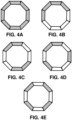
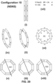
- Other arrangements of the magnetic poles are possible in an octagonal device, such as shown in FIG. 4 .
- all of the poles can be arranged in the same direction, i.e., N/N/N/N/N/N/N/N or N8 (top left of FIG. 4 ), or the magnetic poles can be alternated in each segment, i.e., N/S/N/S/N/S/N/S or NSNSNSNS (bottom of FIG. 4 ).
- Other configurations of the magnetic poles are also available, such as N/S/N/SS/N/S/N or N2SNS2NS, or N/SS/NN/SS/N or N2S2N2S2, or NN/SSSS/NN or N2S4N2, all shown in FIG. 4 .
- a device with 12 segments can be arranged with N12, N6S6, N3S3N3S3, N2SNSNS2NSNS, N2SN2S4N2S, or NSNSNSNSNSNS.
- the mirror images are also possible, such as S2NS2N4S2N, however such configurations are actually identical when viewed from the other side.
- the same principles can be used for devices that have fewer segments, for example, four segments (N4, N2S2, and NSNS), or six segments (N6, N3S3, N2S2NS, and NSNSNS).
- the same principles can be used for devices that include more than twelve segments, for example, sixteen segments (N16, N8S8, N6SNS6NS, N4S4N4S4, N4S2N2S4N2S2, N4SNSNS4NSNS, N3SN3SNS3NS3, N2S2N2S2N2S2, N2S2NSNSN2S2N2S2, N2S2NSN2S2NSN2S2, and NSNSNSNSNSNSNSNSNSNSNS).
- FIG. 6 The benefits of differing magnetic polar configurations are illustrated in FIG. 6 .
- the relative attractive force between two octagons of identical magnetic polar configuration, as the devices are brought closer together, is a function of magnetic polar configuration.
- the total attractive force when devices of the same number of segments are brought into contact should be roughly the same.
- FIG. 7 shows actual force measurements made by securing magnetic arrangements in epoxy and bringing them toward each other with a dynamometer. As can be seen in FIG. 7 , there is marginal difference in force at a distance between N8 and N4S4 octagons. It should be noted that, as shown in FIG. 7 , there is a wide variation of force at a distance of approximately 1 cm (10 mm).
- a surgeon can "tune" the interaction between devices for the desired performance.
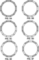
- a surgeon can use two devices with all of the poles arranged in the same direction, i.e., N8. If, on the other hand, the placement of the devices was critical, and the surgeon wanted to minimize the chance that the devices mated before necessary, the surgeon could use a configuration with alternating magnetic poles, i.e., NSNSNSNS. In fact, for some procedures, it may be useful to provide a kit of matched devices with varying magnetic polar configurations, such as shown in FIG. 8 .
- kit would allow a surgeon to choose a desired configuration during the procedure, based upon visualization of the surgical field after the procedure has started.
- a kit could provide "back-up,” in the form of stronger-attracting devices, if the surgeon encountered difficulties joining the tissues during the procedure.
- each magnetic pole is interacting with multiple magnetic segments on the mating device.
- mating devices comprise segments with alternating poles
- a magnetic segment from a first device interacts with at least one opposite pole and two same poles on a nearby mating device.
- the same pole repulsions cancel out a good portion of the opposite pole attraction, resulting in less aggregate attraction at distances of about 1 cm or more.
- a segment of a device having all of the poles arranged in the same direction would only experience attractive forces between it and the segments of the mating device.
- devices of differing numbers of segments i.e., squares, hexagons, octagons, decagons, dodecagons, tetradecagons, hexadecagons, octodecagons, and icosagons can be tuned by selecting particular arrangements of magnetic poles.
- a particular configuration of magnetic poles may be chosen, for example, to cause the devices to overlap correctly, or to cause the devices to connect in a way that insures that the devices cannot revert to their delivery configuration. See e.g., US 2013/0253550 .
- the variability in magnetic polar orientation can be used in a variety of deployable magnetic devices, including both self-opening and self-closing devices, as described below.
- self-opening devices may be constructed having a variety of magnetic polar arrangements, as shown in FIGS. 9A-10B .
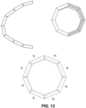
- self-closing devices may be constructed having a variety of magnetic polar arrangements, as shown in FIGS. 12-15 .
- FIGS. 11 and 16 the two configurations (self-opening and self-closing) lend themselves to deployment with different methods, i.e., laparoscopy and endoscopy, respectively. Accordingly, various combinations of devices can be selected, as required, based upon the surgical approach, and the requirements of the anatomy of the patient.
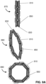
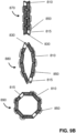
- the deployable magnetic device is self-opening, i.e., as shown in FIGS. 9A-10B .
- Each device comprises a number of magnetic segments 810, wherein two pairs of magnetic segments are linked together at each end of the device with a connection member 830, such as a hinge.
- the magnetic segments 810 between the connection members 830 are linked together with additional connection members 850, which are configured to direct the device to self-convert from a delivery 870 to a deployed 890 configuration.
- connection member may be used herein to refer to a hinge or a polygon-opening member, depending on the application.
- connection member 830 may be referred to herein as a "hinge”
- connection member 850 may be referred to herein as a "polygon-opening member”.
- the polygon-opening members 850 are shown coupled to the exterior of the magnetic segments in FIGS. 9A-10B , the polygon-opening members may also be coupled to the interior of the magnetic segments. In some instances, the polygon-opening members form an exoskeleton over the magnetic segments. The polygon-opening members may be bonded or fastened to the magnetic segments or the polygon-opening members can crimp or grab the magnetic segments.
- each self-opening device comprises two hinges
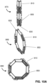
- the number of polygon-opening members 850 depends upon the total number of magnetic segments in the device. For example, for a device that takes the configuration of a square upon deployment, the device will comprise four magnetic segments 810, two hinges 830, and two polygon-opening members 850.
- an octagonal self-opening device may include eight magnetic segments 810, two hinges 830, and six polygon-opening members 850.
- a singular polygon opening member may span two or more magnetic segments 810 (shown in FIG. 10B ).
- a quadrupolar magnetic segment can be used at the hinge end to improve opening.
- Quadrupolar segments are not limited to octagonal configurations, and can be used with any of the configurations described herein.
- a self-opening octagonal device with eight magnetic segments 810, two hinges 830, and two polygon-opening members (see FIG. 10B ).
- deployable self-opening devices having different numbers of magnetic segments that deploy as, e.g., squares, hexagons, decagons, dodecagons, tetradecagons, hexadecagons, octodecagons, or icosagons.
- the self-opening devices of the invention can incorporate a variety of magnetic polar configurations, as shown in FIGS. 9A-10B .
- each segment in the delivery configuration is next to a segment of the same magnetic orientation so that, upon delivery, the magnetic repulsions between segments drives the device into the open (deployed) configuration.
- the primary role of the polygon-opening member is to insure that the device opens in the plane of the polygon; i.e., that out-of-plane motion of the magnetic segments is limited.
- the hinges of the self-opening devices may be constructed from metal (stainless steel, nickel, or nitinol) or plastic, and the hinges may be passive or active, i.e., configured to provide an opening force. In some instances, the hinges are springs.
- the polygon-opening members may be constructed from metal (stainless steel, nickel, or nitinol) or plastic. The polygon opening members are typically active in that they provide a force to drive the device from a delivery configuration to a deployment configuration.
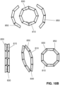
- FIG. 10B An alternate construction of an eight segment, self-opening device of the invention is shown in FIG. 10B .
- the device includes two hinges 830 that help the device transform from a delivery configuration (bottom left) to a deployed configuration (bottom right).
- the device shown in FIG. 10B may be constructed by first coupling two pairs of magnetic segments 810 with hinges 830, and then arranging the remaining magnetic segments 810 in a deployed configuration.
- Each polygon opening member 850 can then be coupled to four segments, including one segment of each hinged pair, to complete the assembly (top of FIG. 10B ).
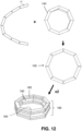
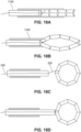
- the self-opening devices of the invention are designed to be delivered in a side-by-side configuration as shown in FIG. 11 .
- a self-opening device can be inserted through a trocar 1100 or other cannula to a location within a patient where the device will be deployed and coupled to a mating device.
- a pusher 1130 will be used to extract the self-opening device from the trocar 1100. Once the device is pushed from the trocar 1100, the device will spontaneously open to form a polygon, as shown in FIGS. 9A-10A .
- the trocar 1100 may be round in cross-section, or the trocar 1100 may be rectangular in cross-section to help the self-opening device to remain in a flat delivery configuration while it is delivered. (See right side of FIG. 11 .)
- non-magnetic inserts 1150 or extruded shaped tubing, may be used to facilitate delivery of a self-opening device.
- Other configurations of self-opening devices i.e., squares, hexagons, decagons, dodecagons, tetradecagons, hexadecagons, octodecagons, and icosagons, can also be delivered in a similar manner.
- the pusher may have a lumen for a guide element as discussed below.
- a laparoscopic manipulator (not shown) will be used to facilitate placement of the deployed device.
- the magnetic devices of the invention are relatively smooth and flat and present essentially uninterrupted annular faces. Because of this design, the devices do not cut or perforate tissue(s), but rather achieve anastomosis by providing steady necrotizing pressure across the contact surface between mating deployed devices. These features also reduce the risks associated with surgical access and ensure that the anastomosis is formed with the correct geometric attributes. Overall, the design ensures the patency of the anastomosis.
- the magnetic segments 140 may be comprised of any strongly-magnetic material, such as rare earth magnetics, comprising materials such as neodymium, samarium, erbium, yttrium, ytterbium, and cobalt.
- the magnetic segments may be coated, e.g., with gold or Teflon, to improve durability or biocompatibility.
- the polygon-closing assembly 120 acts as a hinge between magnetic segments 140 while coupling the structural rigidity of individual segments 140 similar to a cantilevered beam.
- the tensile modulus of the polygon-closing assembly 120 and the polygon-closing assembly's resistance to out-of-plane bending allow the forces on the distal end of the structure to be distributed across the magnetic segments 140.
- the design allows a pushing force on the proximal end of the device in a delivery configuration to reliably move the distal end of the device, e.g., out of a deployment lumen such as the working channel of an endoscope.
- the polygon-closing assembly 120 is thin, and in close contact with the magnetic segments that are long relative to the length of their miter joints, the polygon-closing assembly 120 can bend to accommodate miter closure with relatively small strain.
- the breadth of the polygon-closing assembly 120 produces a high moment of inertia (stiffness) against out-of-polygonal-plane bending, thereby giving good guidance of the growing ring and providing lateral resistance to deflection during closure.
- the polygon-closing assembly 120 also provides a tensile coupling between the magnetic segments, assuring that the segments do not go past the closure point and collapse inward or over top of one-another.
- two self-assembling magnetic compression devices 100 can be associated as a matched set 180.
- tissues that are trapped between the matched set 180 will be compressed, and eventually grow together, leaving an opening 160 in the tissue.
- each magnetic segment of the matched set 180 has at least at least two poles 183 and 185, with the poles oriented normal to the face of the polygon.
- the poles of the segments in adjoining devices are arranged N/S/N/S or S/N/S/N.
- the aligned and matching poles in the matched set 180 form a very strong coupling between the two elements. Additionally, the attractive forces between opposing poles of nearby magnetic segments facilitates assembly of matched set 180.
- the two elements of the matched set 180 need only to be placed in proximity to each other and the magnetic segments will self-align in the preferred configuration. In some instances, it is necessary to pre-align the complimentary devices, however, in other instances the devices self-align by undergoing fast in-plane rotation with respect to one another.
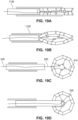
- a guide element 220 such as a suture or wire.
- a variety of attachment points can be used to provide control over the location and deployment of a self-opening or a self-closing magnetic anastomosis device.
- the guide element 220 may extend proximally away from the surgical field and emerge, e.g., from a port or from the proximal end of the working channel of an endoscope.
- the guide element 220 may be coupled to a single distal segment such that, upon deployment, the single distal segment results in an attachment point that provides translational freedom of movement. It is also notable that in the self-closing configuration shown in FIG. 22 , the guide element 220 allows a closing force to be applied to the distal-most segment. That is, in the event that one or more segments should become entangled with tissue, or otherwise prevented from closing, a proximal pulling force with the guide element 220 can help the device to complete self-assembly. Furthermore, once the device has achieved its deployed configuration, the device can be positioned with the guide element 220 to be mated with another device (not shown in FIGS.
- the pusher 1130 can be used to manipulate the device once it has achieved a deployed configuration.
- a guide element 220 may be coupled to the distal-most segment of a self-closing device, and configured to interact with radial members 510 that facilitate assembly and placement of the device.
- proximal force on the guide element 220 helps the device to close.
- the radial members 510 also establish a center 530 of the device, which is coupled to the guide element 220 when the device has achieved a deployment configuration and the guide element 220 is pulled taut. The center 530 of the device can then be delivered to a desired location, e.g., opposite a mating device on the other side of a tissue.
- FIGS. 21A-21D show a different delivery technique, in which a guidewire 1250 is delivered to the area where an anastomosis is to be formed, after which a self-opening device can be delivered to the location using a pusher 1130 (motion shown with hashed arrow) while a sheath 1220 (motion shown with black arrow) is used to keep the self-opening device in a delivery configuration.
- a pusher 1130 motion shown with hashed arrow
- a sheath 1220 motion shown with black arrow
- the pusher 1130 can be used to place the device or help it to mate with a joining device.
- the delivery and deployment may be visualized, e.g., with fluoroscopy or ultrasound, and the device and the pusher 1130 may include markers, such as radiopaque markers, to facilitate visualization. Additionally, while not shown in FIGS. 21A-21D , the device may include one or more guide elements 220 to improve deployment or to facilitate placement.
- the radial members 510 can be fabricated from a variety of materials to achieve the desired mechanical properties and bio-compatibility.
- the radial members 510 may be constructed from metal, e.g., wire, e.g., stainless steel wire, or nickel alloy wire.
- the guide element may be constructed from natural fibers, such as cotton or an animal product.
- the guide element may be constructed from polymers, such as biodegradable polymers, such as polymers including repeating lactic acid, lactone, or glycolic acid units, such as polylactic acid (PLA).
- the guide element may also be constructed from high-tensile strength polymers, such as Tyvek TM (high-density polyethylene fibers) or Kevlar TM (para-aramid fibers).
- the radial members 510 are constructed from biodegradable suture, such as VICRYL TM (polyglactin 910) suture available from Ethicon Corp., Somerville, NJ. Additionally, the radial members 510 can be used in the same configurations regardless of the magnetic polar configuration of the devices.
- VICRYL TM polyglactin 910 suture available from Ethicon Corp., Somerville, NJ. Additionally, the radial members 510 can be used in the same configurations regardless of the magnetic polar configuration of the devices.
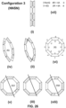
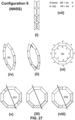
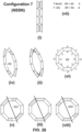
- Azimuthal patterns were calculated for each of the self-opening configurations shown in FIGS. 24-29 .
- each pattern was calculated by drawing each octagonal magnet pattern onto duplicate mylar sheets.
- the potential energy of each segment's interaction with its mating neighbor is either -1, +1 or 0, attractive-repulsive-neutral.
- each of the two inserted quadrupolar segments are deemed to have no interaction with any dipole segment; however a full interaction when one quadrupolar segment aligns with other quadrupole.
- one of the mylar sheets is rotated 45 degrees and the new potential energy tabulated. Repeating this rotation and calculation step eight times results in a list of 8 numbers that describe the rings' interaction through one complete in-plane revolution relative to the other. Additional details of the calculations are presented below.
- the numbers from the calculation are tabulated in an octagonal array (i.e., 12,1:30,3,4:30,6,7:30,9,10:30 on a clockface) where an adjacent number represents the potential energy of the rings after 45 degree rotation of one of the rings.
- the potential energy of the ringpair is actually a smooth curve connecting these most easily calculated locations.
- Each configuration i.e., as shown in FIGS. 24-29 , has multiple diagrams, noted i, ii, iii,..viii. (Cross-hatched is N, solid is S.) Diagrams i, ii, and iii depict the configuration without quadrupolar segments, i.e., "nonQ" versions, whereas iv, v, and viii represent the configuration with the addition of one quadrupolar magnetic segment at each end, i.e., the "2Q" versions.
- each configuration includes a diagram vi that is a depiction of the ring's rotational interaction (nonQ numbers outside, 2Q numbers inside).
- a diagram vi that is a depiction of the ring's rotational interaction (nonQ numbers outside, 2Q numbers inside).
Landscapes
- Health & Medical Sciences (AREA)
- Surgery (AREA)
- Life Sciences & Earth Sciences (AREA)
- Medical Informatics (AREA)
- Animal Behavior & Ethology (AREA)
- Engineering & Computer Science (AREA)
- Biomedical Technology (AREA)
- Heart & Thoracic Surgery (AREA)
- Physiology (AREA)
- Molecular Biology (AREA)
- Nuclear Medicine, Radiotherapy & Molecular Imaging (AREA)
- General Health & Medical Sciences (AREA)
- Public Health (AREA)
- Veterinary Medicine (AREA)
- Surgical Instruments (AREA)
- Endoscopes (AREA)
- Magnetic Treatment Devices (AREA)
- Prostheses (AREA)
Claims (15)
- Selbstöffnende Magnetische-Kompressions-Anastomosevorrichtung, umfassend:
eine Anordnung von zumindest vier magnetischen Segmenten (810), die Ende-an-Ende gekoppelt sind, um ein Polygon zu bilden, welches eine Außerhalb-der-Ebene-Achse aufweist, die durch den Mittelpunkt des Polygons verläuft und normal zur Fläche des Polygons ist, wobei jedes magnetische Segment (810) einen magnetischen Nordpol und einen magnetischen Südpol aufweist, wobei die Anordnung Folgendes umfasst:ein erstes Paar von benachbarten magnetischen Segmenten (810), die mit einem ersten Gelenksverbindungselement (830) bewegbar miteinander gekoppelt sind, sodass die benachbarten magnetischen Segmente des ersten Paars sich relativ zueinander bewegen können; undein zweites Paar von benachbarten magnetischen Segmenten (810), die mit einem zweiten Gelenksverbindungselement (830) bewegbar miteinander gekoppelt sind, sodass die benachbarten magnetischen Segmente des zweiten Paars sich relativ zueinander bewegen können;wobei die Anordnung Folgendes umfasst:eine Platzierungskonfiguration, in der die magnetischen Segmente (810) in zwei Reihen ausgerichtet sind, wobei die zwei Reihen an einem ersten Ende durch das erste Gelenksverbindungselement (830) bewegbar gekoppelt sind und an einem zweiten Ende durch das zweite Gelenksverbindungselement (830) bewegbar gekoppelt sind, wobei die magnetischen Segmente (810) zwischen dem ersten und dem zweiten Gelenksverbindungselement (830) mit polygonöffnenden Verbindungselementen (850) miteinander verbunden sind, undeine entfaltete Konfiguration, in der die magnetischen Segmente (810) das Polygon bilden;dadurch gekennzeichnet, dass das Polygon zumindest teilweise beruhend auf einer Kraft, die durch die polygonöffnenden Verbindungselemente (850) bereitgestellt ist, zur entfalteten Konfiguration ausgebildet sind, undwobei die polygonöffnenden Verbindungselemente (850) aktive Öffnungselemente sind, die ausgelegt sind, um die Kraft bereitzustellen, welche bewirkt, dass die Anordnung von der Platzierungskonfiguration in die entfaltete Konfiguration übergeht. - Anastomosevorrichtung nach Anspruch 1, wobei die Gelenksverbindungselemente (830) passive Verbindungselemente oder aktive Verbindungselemente sind.
- Anastomosevorrichtung nach Anspruch 1, wobei die Nordpole des ersten Paars von magnetischen Segmenten (810) in Bezug auf die Außerhalb-der-Ebene-Achse relativ zueinander fluchtend ausgerichtet sind und die Nordpole des zweiten Paars von magnetischen Segmenten (810) in Bezug auf die Außerhalb-der-Ebene-Achse relativ zueinander fluchtend ausgerichtet sind, und wobei die Nordpole des ersten Paars von magnetischen Segmenten (810) in Bezug auf die Außerhalb-der-Ebene-Achse mit den Nordpolen des zweiten Paars von magnetischen Segmenten (810) fluchtend ausgerichtet sind.
- Anastomosevorrichtung nach Anspruch 1, wobei die Nordpole des ersten Paars von magnetischen Segmenten (810) in Bezug auf die Außerhalb-der-Ebene-Achse relativ zueinander fluchtend angeordnet sind und die Nordpole des zweiten Paars von magnetischen Segmenten (810) in Bezug auf die Außerhalb-der-Ebene-Achse relativ zueinander fluchtend ausgerichtet sind, und wobei die Nordpole des ersten Paars von magnetischen Segmenten (810) in Bezug auf die Außerhalb-der-Ebene-Achse in Bezug auf die Nordpole des zweiten Paars von magnetischen Segmenten (810) in die entgegengesetzte Richtung ausgerichtet sind.
- Anastomosevorrichtung nach Anspruch 1, wobei die magnetischen Nordpole der magnetischen Segmente (810) sich in Bezug auf eine Oberseite und eine Unterseite des Polygons von Segment zu Segment hinsichtlich ihrer Orientierung abwechseln.
- Anastomosevorrichtung nach Anspruch 1, wobei die Anordnung zumindest vier magnetische Segmente (810) umfasst, wobei das Polygon eine Oberseite und eine Unterseite aufweist und die magnetischen Nordpole von zumindest zwei magnetischen Segmenten (810) in Richtung der Oberseite des Polygons angeordnet sind und die magnetischen Nordpole von zumindest zwei magnetischen Segmenten (810) in Richtung der Unterseite des Polygons angeordnet sind.
- Anastomosevorrichtung nach Anspruch 6, wobei die magnetischen Nordpole der magnetischen Segmente (810) sich in Bezug auf die Oberseite und Unterseite des Polygons von Segment zu Segment hinsichtlich ihrer Orientierung abwechseln.
- Anastomosevorrichtung nach Anspruch 7, wobei die Anordnung ein erstes magnetisches Segment (810), ein zweites magnetisches Segment (810), das unmittelbar benachbart zum ersten magnetischen Segment (810) ist, ein drittes magnetisches Segment (810), das unmittelbar benachbart zum zweiten magnetischen Segment (810) ist, und ein viertes magnetisches Segment (810), das unmittelbar benachbart zum dritten und ersten magnetischen Segment (810) ist, umfasst.
- Anastomosevorrichtung nach Anspruch 8, wobei die magnetischen Nordpole des ersten und dritten magnetischen Segments (810) in Richtung der Oberseite des Polygons angeordnet sind und die magnetischen Nordpole des zweiten und vierten magnetischen Segments (810) in Richtung der Bodenseite des Polygons angeordnet sind.
- Anastomosevorrichtung nach Anspruch 6, wobei die Anordnung acht magnetische Segmente (810) umfasst, sodass die Anordnung ferner Folgendes umfasst:ein drittes Paar von magnetischen Segmenten (810), die zusammen mit einem ersten der polygonöffnenden Verbindungselemente (850) gekoppelt sind; undein viertes Paar von magnetischen Segmenten (810), die zusammen mit einem zweiten der polygonöffnenden Verbindungselemente (850) gekoppelt sind;wobei in der Platzierungskonfiguration das dritte Paar von magnetischen Segmenten (810) sich in der ersten Reihe befindet und über ein drittes und viertes polygonöffnendes Verbindungselement (850) mit dem ersten und zweiten Paar von magnetischen Segmenten (810) gekoppelt ist, das vierte Paar von magnetischen Segmenten (810) sich in der zweiten Reihe befindet und über ein fünftes und sechstes polygonöffnendes Verbindungselement (850) mit dem ersten und zweiten Paar von magnetischen Segmenten (810) gekoppelt ist, und wobei die magnetischen Segmente (810) in der entfalteten Konfiguration zumindest teilweise beruhend auf einer Kraft, die von zumindest einem aus dem ersten, zweiten, dritten, vierten, fünften und sechsten polygonöffnenden Verbindungselement (850) bereitgestellt ist, das Polygon ausbilden.
- Anastomosevorrichtung nach Anspruch 10, wobei die Anordnung ein erstes magnetisches Segment (810), ein zweites magnetisches Segment (810), das unmittelbar benachbart zum ersten magnetischen Segment (810) ist, ein drittes magnetisches Segment (810), das unmittelbar benachbart zum zweiten magnetischen Segment (810) ist, ein viertes magnetisches Segment (810), das unmittelbar benachbart zum dritten magnetischen Segment (810) ist, ein fünftes magnetisches Segment (810), das unmittelbar benachbart zum vierten magnetischen Segment (810) ist, ein sechstes magnetisches Segment (810), das unmittelbar benachbart zum fünften magnetischen Segment (810) ist, ein siebtes magnetisches Segment (810), das unmittelbar benachbart zum sechsten magnetischen Segment (810) ist, und ein achtes magnetisches Segment (810), das unmittelbar benachbart zum ersten und siebten magnetischen Segment (810) ist, umfasst.
- Anastomose nach Anspruch 11, wobei die magnetischen Nordpole des ersten, dritten, fünften und siebten magnetischen Segments (810) in Richtung der Oberseite des Polygons angeordnet sind, und die magnetischen Nordpole des zweiten, vierten, sechsten und achten magnetischen Segments (810) in Richtung der Unterseite des Polygons angeordnet sind.
- Anastomosevorrichtung nach Anspruch 1, wobei eines oder mehrere der Verbindungselemente (830, 850) ein Edelstahl, Kunststoff- oder Nitinolmaterial umfassen.
- Anastomosevorrichtung nach Anspruch 1, wobei das eine oder die mehreren Verbindungselemente (830, 850) mit dem Äußeren von zwei magnetischen Segmenten gekoppelt ist/sind, wobei zumindest eines der Verbindungselemente (830, 850), die mit dem Äußeren von zwei magnetischen Segmenten gekoppelt sind, ein Exoskelett über den zwei magnetischen Segmenten ausbildet.
- Anastomosevorrichtung nach Anspruch 1, wobei die Anordnung von magnetischen Segmenten (810) ausgelegt ist, um mit einem Führungsdraht gekoppelt zu sein, und ausgelegt ist, um sich entlang der Länge des Führungsdrahts zu verschieben, wenn sie von der Platzierungskonfiguration in die entfaltete Konfiguration übergeht.
Applications Claiming Priority (2)
| Application Number | Priority Date | Filing Date | Title |
|---|---|---|---|
| US201562132075P | 2015-03-12 | 2015-03-12 | |
| PCT/US2016/022209 WO2016145414A1 (en) | 2015-03-12 | 2016-03-11 | Magnetic anastomosis devices with varying magnetic force at a distance |
Publications (2)
| Publication Number | Publication Date |
|---|---|
| EP3267905A1 EP3267905A1 (de) | 2018-01-17 |
| EP3267905B1 true EP3267905B1 (de) | 2025-05-07 |
Family
ID=55588638
Family Applications (1)
| Application Number | Title | Priority Date | Filing Date |
|---|---|---|---|
| EP16711492.5A Active EP3267905B1 (de) | 2015-03-12 | 2016-03-11 | Magnetische anastomosevorrichtung mit variierender magnetkraft bei einem abstand |
Country Status (8)
| Country | Link |
|---|---|
| US (4) | US10517600B2 (de) |
| EP (1) | EP3267905B1 (de) |
| JP (4) | JP6923446B2 (de) |
| CN (1) | CN107889454B (de) |
| BR (1) | BR112017019408A2 (de) |
| ES (1) | ES3032508T3 (de) |
| MX (1) | MX2017011638A (de) |
| WO (1) | WO2016145414A1 (de) |
Families Citing this family (52)
| Publication number | Priority date | Publication date | Assignee | Title |
|---|---|---|---|---|
| WO2011008988A1 (en) | 2009-07-15 | 2011-01-20 | Medical And Surgical Review, P.C. | Incisionless gastric bypass method and devices |
| US8828032B2 (en) | 2010-01-05 | 2014-09-09 | GI Windows, Inc. | Methods and apparatus for magnet-induced compression anastomosis between adjacent organs |
| US8870898B2 (en) | 2010-01-05 | 2014-10-28 | GI Windows, Inc. | Self-assembling magnetic anastomosis device having an exoskeleton |
| WO2013009886A1 (en) | 2011-07-12 | 2013-01-17 | Ircad | Modular magnetic anastomosis device |
| WO2014102621A2 (en) | 2012-12-21 | 2014-07-03 | Ircad | Applicators for modular magnetic anastomosis device |
| EP3267905B1 (de) | 2015-03-12 | 2025-05-07 | GI Windows Inc. | Magnetische anastomosevorrichtung mit variierender magnetkraft bei einem abstand |
| CN108024856B (zh) * | 2015-06-05 | 2019-10-25 | 坦迪尼控股股份有限公司 | 人造二尖瓣的经血管递送的尖端控制 |
| US10561423B2 (en) | 2016-07-25 | 2020-02-18 | Virender K. Sharma | Cardiac shunt device and delivery system |
| WO2018022180A1 (en) | 2016-07-25 | 2018-02-01 | Sharma Virender K | Magnetic anastomosis device delivery system |
| US12364480B2 (en) | 2016-07-25 | 2025-07-22 | Virender K. Sharma | Magnetic anastomosis device with opposing coil directionality |
| US11304698B2 (en) | 2016-07-25 | 2022-04-19 | Virender K. Sharma | Cardiac shunt device and delivery system |
| EP4442209A3 (de) * | 2017-06-30 | 2025-03-05 | Regents of the University of California | Magnetische vorrichtungen und systeme |
| CN108635003A (zh) * | 2018-05-15 | 2018-10-12 | 中国人民解放军陆军军医大学第三附属医院(野战外科研究所) | 一种食管吻合口狭窄组合切割装置 |
| EP3801299B1 (de) | 2018-06-02 | 2024-01-03 | GI Windows Inc. | Vorrichtungen zur herstellung von anastomosen |
| CN109223073B (zh) * | 2018-11-23 | 2024-07-02 | 上海安翰医疗技术有限公司 | 磁性辅助件及具有磁性辅助件的微创手术辅助装置 |
| CN114423360B (zh) * | 2019-04-10 | 2024-12-13 | 维兰德·K·沙马 | 具有嵌入式引流机构的磁性吻合装置 |
| CN113825455B (zh) * | 2019-04-30 | 2024-08-30 | 波士顿科学国际有限公司 | 内窥镜贴片施用器 |
| EP3964141A1 (de) | 2020-09-02 | 2022-03-09 | Technische Universität München | Implantat und implantatapplikator für chirurgische anastomose |
| CA3192930A1 (en) | 2020-09-18 | 2022-03-24 | Michel Gagner | Anastomosis formation with magnetic devices having temporary retention member |
| US11534171B2 (en) | 2020-12-18 | 2022-12-27 | Gt Metabolic Solutions, Inc. | Devices and methods for assisting magnetic compression anastomosis |
| EP4291111A1 (de) | 2021-02-12 | 2023-12-20 | Medvie Limited | Kompressionsanastomosesystem und verwendung davon |
| WO2022225923A1 (en) | 2021-04-20 | 2022-10-27 | G.I. Windows, Inc. | Systems, devices, and methods for endoscope or laparoscopic magnetic navigation |
| EP4329638A4 (de) | 2021-04-30 | 2025-02-26 | GT Metabolic Solutions, Inc. | Anastomosebildung mit magnetischen vorrichtungen mit bioresorbierbarem halteelement |
| WO2022265724A1 (en) * | 2021-06-16 | 2022-12-22 | G.I. Windows, Inc. | Magnetic anastomosis devices with varying magnetic force at a distance |
| WO2023052962A1 (en) | 2021-09-29 | 2023-04-06 | Cilag Gmbh International | Methods and systems for controlling cooperative surgical instruments |
| US12290319B2 (en) | 2021-09-29 | 2025-05-06 | Cilag Gmbh International | Methods for controlling cooperative surgical instruments |
| WO2023052938A1 (en) | 2021-09-29 | 2023-04-06 | Cilag Gmbh International | Methods and systems for controlling cooperative surgical instruments |
| US12137986B2 (en) | 2021-09-29 | 2024-11-12 | Cilag Gmbh International | Methods for controlling cooperative surgical instruments |
| US12364545B2 (en) | 2021-09-29 | 2025-07-22 | Cilag Gmbh International | Surgical devices, systems, and methods using fiducial identification and tracking |
| US12376910B2 (en) | 2021-09-29 | 2025-08-05 | Cilag Gmbh International | Methods for controlling cooperative surgical instruments |
| US12137872B2 (en) | 2021-09-29 | 2024-11-12 | Cilag Gmbh International | Surgical devices, systems, and methods using multi-source imaging |
| EP4221602A1 (de) | 2021-09-29 | 2023-08-09 | Cilag GmbH International | Verfahren und systeme zur steuerung kooperativer chirurgischer instrumente |
| US12295667B2 (en) | 2021-09-29 | 2025-05-13 | Cilag Gmbh International | Surgical devices, systems, and methods using multi-source imaging |
| US12239387B2 (en) | 2021-09-29 | 2025-03-04 | Cilag Gmbh International | Surgical methods using fiducial identification and tracking |
| CA3207008A1 (en) | 2021-10-15 | 2023-04-20 | Ballast Medical Inc. | Magnetic devices for resectioning a portion of a bodily organ |
| US20230190277A1 (en) | 2021-12-16 | 2023-06-22 | Cilag Gmbh International | Implantable sphincter assistance device with concentrated or diffused bead-to-bead magnetic field interactions |
| US12213675B2 (en) | 2021-12-16 | 2025-02-04 | Cilag Gmbh International | Implantable sphincter assistance device with holding, aligning or clamping features integrated into housing |
| US11957353B2 (en) | 2021-12-16 | 2024-04-16 | Cilag Gmbh International | Implantable sphincter assistance device with redirected or focused magnetic fields for interaction between adjacent beads |
| US11957352B2 (en) | 2021-12-16 | 2024-04-16 | Cilag Gmbh International | Implantable sphincter assistance device with controlled homogeneous dilation of the restricting elements |
| US12310593B2 (en) | 2021-12-16 | 2025-05-27 | Cilag Gmbh International | Implantable sphincter device with bead orientation control based on bead interactive geometry |
| US12161544B2 (en) | 2021-12-16 | 2024-12-10 | Cilag Gmbh International | Implantable sphincter assistance device sealing and attachment elements for connection of beads |
| US12213678B2 (en) | 2021-12-16 | 2025-02-04 | Cilag Gmbh International | Implantable sphincter assistance device with 3D printed magnetic elements |
| USD1081998S1 (en) | 2022-03-17 | 2025-07-01 | Gt Metabolic Solutions, Inc. | Anastomosis formation device |
| US11712237B1 (en) * | 2022-07-20 | 2023-08-01 | Samothrace Medical Innovations, Inc. | Anatomical tissue anchor and related methods |
| WO2024030575A1 (en) | 2022-08-05 | 2024-02-08 | G.I. Windows, Inc. | Magnetic compression anastomosis device with multipiece vertebra |
| US20240065694A1 (en) * | 2022-08-25 | 2024-02-29 | G.I. Windows, Inc. | Magnetic compression anastomosis devices with multipiece internal vertebrae support structures |
| JP2025529235A (ja) | 2022-09-01 | 2025-09-04 | ジーアイ ウィンドウズ, インコーポレイテッド | 圧力プロファイル磁気圧縮吻合デバイス |
| JP2025529236A (ja) | 2022-09-02 | 2025-09-04 | ジーアイ ウィンドウズ, インコーポレイテッド | 内視鏡または腹腔鏡磁気ナビゲーションのためのシステム、デバイスおよび方法 |
| WO2024263764A2 (en) * | 2023-06-21 | 2024-12-26 | Gt Metabolic Solutions, Inc. | Magnetic implants having through-holes for forming an anastomosis |
| WO2025064986A1 (en) * | 2023-09-22 | 2025-03-27 | G.I. Windows, Inc. | Systems, devices, and methods for delivery of otomy support and anastomosis creation devices |
| WO2025149991A1 (en) * | 2024-01-12 | 2025-07-17 | Multi-Scale Medical Robotics Center Limited | System and method for endoluminal tissue manipulation |
| CN119184773B (zh) * | 2024-09-18 | 2025-06-27 | 中国人民解放军总医院第二医学中心 | 一种用于消化内镜下组织夹闭的磁吻合设备 |
Citations (1)
| Publication number | Priority date | Publication date | Assignee | Title |
|---|---|---|---|---|
| WO2013176993A1 (en) * | 2012-05-19 | 2013-11-28 | G. I. Windows, Inc. | Self-assembling magnetic anastomosis device having an exoskeleton |
Family Cites Families (163)
| Publication number | Priority date | Publication date | Assignee | Title |
|---|---|---|---|---|
| CH591237A5 (de) | 1975-11-06 | 1977-09-15 | Bbc Brown Boveri & Cie | |
| DE3011742A1 (de) | 1980-03-26 | 1981-10-01 | Siemens AG, 1000 Berlin und 8000 München | Magnetische verschlussvorrichtung fuer einen darmausgang |
| US4538130A (en) | 1984-04-23 | 1985-08-27 | Field Effects, Inc. | Tunable segmented ring magnet and method of manufacture |
| RU2018266C1 (ru) | 1989-03-27 | 1994-08-30 | Цап Наталья Александровна | Способ оперативного лечения двуствольных кишечных свищей |
| SU1708313A1 (ru) | 1989-07-20 | 1992-01-30 | 2-й Московский государственный медицинский институт им.Н.И.Пирогова | Способ формировани магнитного компрессионного холецистогастроанастомоза |
| SU1725851A1 (ru) | 1990-01-15 | 1992-04-15 | Киевский Медицинский Институт Им.Акад.А.А.Богомольца | Устройство дл наложени анастомозов |
| DE4039320A1 (de) | 1990-12-10 | 1992-06-11 | Kloeckner Humboldt Deutz Ag | Magnetsystem |
| US5320629B1 (en) | 1991-01-07 | 2000-05-02 | Advanced Surgical Inc | Device and method for applying suture |
| US5381784A (en) | 1992-09-30 | 1995-01-17 | Adair; Edwin L. | Stereoscopic endoscope |
| IL116699A (en) | 1996-01-08 | 2001-09-13 | Biosense Ltd | Method of building a heart map |
| US5431670A (en) | 1993-10-13 | 1995-07-11 | Hol-Med Corporation | Surgical suturing instrument |
| US5595562A (en) | 1994-11-10 | 1997-01-21 | Research Corporation Technologies, Inc. | Magnetic enteral gastrostomy |
| WO1996039077A1 (en) | 1995-06-06 | 1996-12-12 | Corvita Corporation | Endovascular measuring apparatus, loading and deployment means |
| US5690656A (en) | 1995-06-27 | 1997-11-25 | Cook Incorporated | Method and apparatus for creating abdominal visceral anastomoses |
| JPH11514269A (ja) | 1995-10-13 | 1999-12-07 | トランスバスキュラー インコーポレイテッド | 動脈閉塞にバイパスを形成するためのおよび/またはその他の経血管的手法を実施するための方法および装置 |
| US6129668A (en) | 1997-05-08 | 2000-10-10 | Lucent Medical Systems, Inc. | System and method to determine the location and orientation of an indwelling medical device |
| US6352543B1 (en) | 2000-04-29 | 2002-03-05 | Ventrica, Inc. | Methods for forming anastomoses using magnetic force |
| US6132458A (en) | 1998-05-15 | 2000-10-17 | American Medical Systems, Inc. | Method and device for loading a stent |
| US6478210B2 (en) | 2000-10-25 | 2002-11-12 | Scimed Life Systems, Inc. | Method and device for full thickness resectioning of an organ |
| US6537284B1 (en) | 1998-10-29 | 2003-03-25 | Kanji Inoue | Device for guiding an appliance |
| US7125403B2 (en) | 1998-12-08 | 2006-10-24 | Intuitive Surgical | In vivo accessories for minimally invasive robotic surgery |
| US6190303B1 (en) | 1999-01-25 | 2001-02-20 | Isostent, Inc. | Shield assembly with removable inner-tube apparatus for radioactive stents |
| US6428550B1 (en) | 1999-05-18 | 2002-08-06 | Cardica, Inc. | Sutureless closure and deployment system for connecting blood vessels |
| JP3901421B2 (ja) | 1999-08-19 | 2007-04-04 | 有限会社 パックス オプティカ ジャパン | 臓器吻合装置 |
| WO2001078801A2 (en) | 2000-04-12 | 2001-10-25 | Ventrica, Inc. | Method and apparatus for placing a conduit |
| US20050080439A1 (en) * | 2000-04-29 | 2005-04-14 | Carson Dean F. | Devices and methods for forming magnetic anastomoses and ports in vessels |
| US8518062B2 (en) | 2000-04-29 | 2013-08-27 | Medtronic, Inc. | Devices and methods for forming magnetic anastomoses between vessels |
| US6802847B1 (en) | 2000-04-29 | 2004-10-12 | Ventrica, Inc. | Devices and methods for forming magnetic anastomoses and ports in vessels |
| US7232449B2 (en) | 2000-04-29 | 2007-06-19 | Medtronic, Inc. | Components, systems and methods for forming anastomoses using magnetism or other coupling means |
| US6663598B1 (en) | 2000-05-17 | 2003-12-16 | Scimed Life Systems, Inc. | Fluid seal for endoscope |
| US6530934B1 (en) | 2000-06-06 | 2003-03-11 | Sarcos Lc | Embolic device composed of a linear sequence of miniature beads |
| US7909837B2 (en) | 2000-12-13 | 2011-03-22 | Medtronic, Inc. | Methods, devices and systems for forming magnetic anastomoses |
| US20020143347A1 (en) | 2000-12-13 | 2002-10-03 | Ventrica, Inc. | Extravascular anastomotic components and methods for forming vascular anastomoses |
| US6558400B2 (en) | 2001-05-30 | 2003-05-06 | Satiety, Inc. | Obesity treatment tools and methods |
| US6827718B2 (en) | 2001-08-14 | 2004-12-07 | Scimed Life Systems, Inc. | Method of and apparatus for positioning and maintaining the position of endoscopic instruments |
| CN1963962B (zh) * | 2001-08-24 | 2012-07-04 | 澳大利亚儿童玩具控股有限公司 | 可变换的磁性装置 |
| ITMI20012829A1 (it) | 2001-12-28 | 2003-06-28 | Gambro Dasco Spa | Apparecchiatura e metodo di controllo in un circuito extracorporeo disangue |
| US7025759B2 (en) | 2002-02-04 | 2006-04-11 | Ebi, L.P. | Steerable catheter |
| US7060025B2 (en) | 2002-03-15 | 2006-06-13 | Ethicon Endo-Surgery, Inc. | Method for controlling position of medical instruments |
| US6699263B2 (en) | 2002-04-05 | 2004-03-02 | Cook Incorporated | Sliding suture anchor |
| JP3930757B2 (ja) | 2002-04-10 | 2007-06-13 | 有限会社 パックス オプティカ ジャパン | 臓器吻合装置 |
| US7695427B2 (en) * | 2002-04-26 | 2010-04-13 | Torax Medical, Inc. | Methods and apparatus for treating body tissue sphincters and the like |
| US20050256503A1 (en) | 2002-05-07 | 2005-11-17 | Cardiac Pacemakers, Inc. | Tapered catheter delivery system |
| US11382791B2 (en) | 2003-07-21 | 2022-07-12 | Vanderbilt University | Drug delivery device and applications of same |
| US7618427B2 (en) | 2003-12-29 | 2009-11-17 | Ethicon Endo-Surgery, Inc. | Device and method for intralumenal anastomosis |
| JP4145248B2 (ja) | 2004-01-22 | 2008-09-03 | 信越化学工業株式会社 | 永久磁石式磁界発生装置 |
| US7282057B2 (en) | 2004-03-30 | 2007-10-16 | Wilson-Cook Medical, Inc. | Pediatric atresia magnets |
| US7736379B2 (en) | 2004-06-09 | 2010-06-15 | Usgi Medical, Inc. | Compressible tissue anchor assemblies |
| US20060036267A1 (en) | 2004-08-11 | 2006-02-16 | Usgi Medical Inc. | Methods and apparatus for performing malabsorptive bypass procedures within a patient's gastro-intestinal lumen |
| US8043290B2 (en) | 2004-09-29 | 2011-10-25 | The Regents Of The University Of California, San Francisco | Apparatus and methods for magnetic alteration of deformities |
| US8142454B2 (en) | 2004-09-29 | 2012-03-27 | The Regents Of The University Of California, San Francisco | Apparatus and method for magnetic alteration of anatomical features |
| US8915915B2 (en) | 2004-09-29 | 2014-12-23 | The Regents Of The University Of California | Apparatus and methods for magnetic alteration of anatomical features |
| US20060271107A1 (en) | 2004-09-29 | 2006-11-30 | Harrison Michael R | Apparatus and methods for magnetic alteration of anatomical features |
| US8623036B2 (en) | 2004-09-29 | 2014-01-07 | The Regents Of The University Of California | Magnamosis |
| US8439915B2 (en) | 2004-09-29 | 2013-05-14 | The Regents Of The University Of California | Apparatus and methods for magnetic alteration of anatomical features |
| DE602005027608D1 (de) | 2004-10-25 | 2011-06-01 | Merit Medical Systems Inc | Vorrichtung zum entfernen und versetzen eines stents |
| EP1830714B1 (de) | 2004-12-15 | 2012-07-11 | Cook Medical Technologies LLC | Flexible chirurgische nadelvorrichtung |
| US20100010610A1 (en) | 2005-03-18 | 2010-01-14 | The Board Of Trustees Of The University Of Illinois | Anastomosis stent and graft apparatus and method |
| JP4681920B2 (ja) | 2005-03-30 | 2011-05-11 | オリンパスメディカルシステムズ株式会社 | 体腔内に留置される留置具 |
| US8342183B2 (en) | 2006-04-19 | 2013-01-01 | Vibrynt, Inc. | Devices and methods for treatment of obesity |
| BRPI0603437A2 (pt) | 2006-06-06 | 2010-07-06 | Luiz Gonzaga Granja Jr | prótese para anastomose tipo stent extraluminal |
| US20080051626A1 (en) | 2006-08-28 | 2008-02-28 | Olympus Medical Systems Corp. | Fistulectomy method between first duct and second duct, ultrasonic endoscope, catheter with balloon, magnet retaining device, and magnet set |
| US9814557B2 (en) | 2006-10-10 | 2017-11-14 | Boston Scientific Scimed, Inc. | Stent protector design |
| US20080114384A1 (en) * | 2006-11-10 | 2008-05-15 | Wilson-Cook Medical Inc. | Ring magnets for surgical procedures |
| WO2008073985A2 (en) | 2006-12-12 | 2008-06-19 | Zelickson Brian D | Laser energy device for soft tissue removal |
| US9125761B2 (en) | 2007-01-25 | 2015-09-08 | Boston Scientific Scimed, Inc. | Endoscope with preloaded or preloadable stent |
| US20080200933A1 (en) | 2007-02-15 | 2008-08-21 | Bakos Gregory J | Surgical devices and methods for forming an anastomosis between organs by gaining access thereto through a natural orifice in the body |
| US20080200934A1 (en) | 2007-02-15 | 2008-08-21 | Fox William D | Surgical devices and methods using magnetic force to form an anastomosis |
| EP2124759B1 (de) | 2007-02-28 | 2011-06-29 | Wilson-Cook Medical Inc. | Intestinaler bypass unter verwendung von magneten |
| US8506516B2 (en) | 2007-05-29 | 2013-08-13 | Cvdevices, Llc | Devices, systems, and methods for achieving magnetic gastric bypass |
| EP2182885B1 (de) | 2007-08-27 | 2015-03-04 | Torax Medical, Inc. | Magnetisches magenband oder ähnliches |
| JP5378386B2 (ja) * | 2007-10-09 | 2013-12-25 | クック メディカル テクノロジーズ エルエルシー | 改善された給送特性を有する磁気吻合器具 |
| CA2746083C (en) | 2007-12-21 | 2016-02-23 | Medical And Surgical Review, P.C. | Methods and devices for endoscopically creating an anastomosis |
| US8262680B2 (en) | 2008-03-10 | 2012-09-11 | Ethicon Endo-Surgery, Inc. | Anastomotic device |
| CA2720648A1 (en) | 2008-04-08 | 2009-10-15 | Reverse Medical Corporation | Occlusion device and method of use |
| US8162958B2 (en) | 2008-07-11 | 2012-04-24 | Olympus Medical Systems Corp. | Tissue fastening tool and applicator for indwelling the same within body, and tissue fastening method through natural orifice |
| US8685046B2 (en) | 2008-08-05 | 2014-04-01 | Covidien Lp | Magnetic compression anastomosis device |
| US8241204B2 (en) | 2008-08-29 | 2012-08-14 | Ethicon Endo-Surgery, Inc. | Articulating end cap |
| US9173669B2 (en) | 2008-09-12 | 2015-11-03 | Pneumrx, Inc. | Enhanced efficacy lung volume reduction devices, methods, and systems |
| US8828031B2 (en) | 2009-01-12 | 2014-09-09 | Ethicon Endo-Surgery, Inc. | Apparatus for forming an anastomosis |
| US8679139B2 (en) | 2009-04-03 | 2014-03-25 | Cook Medical Technologies Llc | Delivery system for magnetic anastomosis device |
| JP5449534B2 (ja) | 2009-05-15 | 2014-03-19 | クック メディカル テクノロジーズ エルエルシー | 磁気吻合デバイス用送達システム |
| WO2011008988A1 (en) | 2009-07-15 | 2011-01-20 | Medical And Surgical Review, P.C. | Incisionless gastric bypass method and devices |
| US20110087252A1 (en) | 2009-10-08 | 2011-04-14 | Wilson-Cook Medical Inc. | Biliary decompression and anastomosis stent |
| US20110098731A1 (en) | 2009-10-26 | 2011-04-28 | Eric Whitbrook | Magnetically assisted clasps for prosthetic implants, and related methods |
| US20110118765A1 (en) | 2009-11-18 | 2011-05-19 | Aguirre Andres F | Anastomosis stent |
| US8728105B2 (en) | 2009-12-30 | 2014-05-20 | Cook Medical Technologies Llc | Elongate magnet for a magnetic anastomosis device |
| US8828032B2 (en) | 2010-01-05 | 2014-09-09 | GI Windows, Inc. | Methods and apparatus for magnet-induced compression anastomosis between adjacent organs |
| US8870898B2 (en) | 2010-01-05 | 2014-10-28 | GI Windows, Inc. | Self-assembling magnetic anastomosis device having an exoskeleton |
| US8382779B2 (en) | 2010-02-22 | 2013-02-26 | Vibrant Med-El Hearing Technology Gmbh | Vascular clamps for vascular repair |
| US8603121B2 (en) | 2010-04-14 | 2013-12-10 | Cook Medical Technologies Llc | Systems and methods for creating anastomoses |
| US8636751B2 (en) | 2010-05-26 | 2014-01-28 | Ethicon Endo-Surgery, Inc. | Methods and devices for the rerouting of chyme to induce intestinal brake |
| US20130066136A1 (en) | 2010-11-24 | 2013-03-14 | Mount Sinai School Of Medicine | Magnetic based device for retrieving a misplaced article |
| US9332990B2 (en) * | 2010-12-30 | 2016-05-10 | Wake Forest University Health Sciences | Ureter to ileal conduit anastomosis using magnetic compression and related delivery devices and methods |
| WO2012125785A1 (en) | 2011-03-17 | 2012-09-20 | Ethicon Endo-Surgery, Inc. | Hand held surgical device for manipulating an internal magnet assembly within a patient |
| WO2013009886A1 (en) * | 2011-07-12 | 2013-01-17 | Ircad | Modular magnetic anastomosis device |
| KR101330397B1 (ko) | 2011-11-01 | 2013-11-15 | 재단법인 아산사회복지재단 | 자가 팽창성을 가지는 물질 또는 구조를 이용한 혈관 문합용 구조물 및 이를 이용한 혈관 문합 방법 |
| CN202437231U (zh) * | 2012-02-06 | 2012-09-19 | 徐忠法 | 磁力压迫吻合球 |
| WO2013126246A1 (en) | 2012-02-23 | 2013-08-29 | Cook Medical Technologies Llc | Pediatric esophageal atresia magnetic anastomosis system |
| WO2013173045A1 (en) | 2012-05-17 | 2013-11-21 | Xlumena, Inc. | Methods and devices for access across adjacent tissue layers |
| US20130325042A1 (en) | 2012-05-31 | 2013-12-05 | Izhak Fabian | Pylorus plug and anastomosis |
| US9305140B2 (en) | 2012-07-16 | 2016-04-05 | Georgetown University | System and method of applying state of being to health care delivery |
| CN102835985A (zh) * | 2012-08-15 | 2012-12-26 | 西安交通大学 | 一种限制性门腔分流磁性吻合环 |
| WO2014039369A1 (en) | 2012-09-04 | 2014-03-13 | A.M. Surgical, Inc. | Compact endoscopic surgical blade assembly and method of use thereof |
| IN2015DN02106A (de) | 2012-09-07 | 2015-08-14 | Ethicon Endo Surgery Inc | |
| WO2014102621A2 (en) | 2012-12-21 | 2014-07-03 | Ircad | Applicators for modular magnetic anastomosis device |
| JP6342431B2 (ja) | 2013-02-21 | 2018-06-13 | ボストン サイエンティフィック サイムド,インコーポレイテッドBoston Scientific Scimed,Inc. | 吻合を形成するためのステントおよび同ステントを含む医療用具 |
| US9144370B2 (en) | 2013-02-28 | 2015-09-29 | Canon Usa Inc. | Mechanical structure of articulated sheath |
| US9248037B2 (en) | 2013-03-15 | 2016-02-02 | Cook Medical Technologies Llc | Automatic wireless medical device release mechanism |
| US20140309669A1 (en) | 2013-04-14 | 2014-10-16 | Izhak Fabian | Positioning tool for anastomosis |
| US11033272B2 (en) | 2013-04-16 | 2021-06-15 | Ethicon Endo-Surgery, Inc. | Methods for partial diversion of the intestinal tract |
| US9364238B2 (en) | 2013-04-16 | 2016-06-14 | Ethicon Endo-Surgery, Inc. | Method and apparatus for joining hollow organ sections in anastomosis |
| US9788983B2 (en) | 2013-06-21 | 2017-10-17 | Abbott Cardiovascular Systems Inc. | Removable sheath assembly for a polymer scaffold |
| EP2839796A1 (de) | 2013-08-23 | 2015-02-25 | Cook Medical Technologies LLC | Endovaskuläres Verabreichungssystem für vaskuläre Anastomose mit magnetischer Kompression |
| US10039550B2 (en) | 2013-12-31 | 2018-08-07 | Easy Notes Ltd. | Magnetic anastomosis assembly |
| JP5782596B2 (ja) | 2014-01-29 | 2015-09-24 | 鈴木 麻美 | 磁気治療器具 |
| KR20150102567A (ko) | 2014-02-28 | 2015-09-07 | 연세대학교 산학협력단 | 문합술용 고정기구 |
| US20150313595A1 (en) | 2014-05-02 | 2015-11-05 | W. L. Gore & Associates, Inc. | Anastomosis Devices |
| BR112017001345A2 (pt) | 2014-07-23 | 2017-11-14 | Gi Windows Inc | dispositivos de anastomose magnética, sistema de anastomose de compressão magnética e método para criar uma anastomose em um tecido |
| US9943335B2 (en) | 2014-09-23 | 2018-04-17 | Cook Medical Technologies Llc | Implanted magnets retrieval system and method |
| US10376400B2 (en) | 2014-10-10 | 2019-08-13 | Rex Medical, L.P. | Gastric bypass system and method |
| CN104398281B (zh) | 2014-11-27 | 2017-02-22 | 史源 | 一种子母式外科吻合磁环 |
| EP3267905B1 (de) | 2015-03-12 | 2025-05-07 | GI Windows Inc. | Magnetische anastomosevorrichtung mit variierender magnetkraft bei einem abstand |
| WO2016183039A1 (en) | 2015-05-08 | 2016-11-17 | GI Windows, Inc. | Systems, devices, and methods for forming anastomoses |
| US10426927B2 (en) | 2015-06-02 | 2019-10-01 | Clph, Llc | Telescoping catheters and methods for use |
| CN105011985B (zh) | 2015-07-21 | 2017-06-06 | 史源 | 一种包皮磁环吻合器 |
| CN205379345U (zh) | 2015-12-18 | 2016-07-13 | 史源 | 一种磁性吻合环 |
| EP3402426A4 (de) | 2016-01-15 | 2019-08-28 | TVA Medical, Inc. | Systeme und verfahren zum anhaften von gefässen |
| JP2019509814A (ja) | 2016-03-16 | 2019-04-11 | ジーアイ ウィンドウズ, インコーポレイテッド | 磁気吻合デバイスの正確な設置を提供するための標的化システム |
| US11076856B2 (en) | 2016-05-23 | 2021-08-03 | Mor Research Applications Ltd. | Anastomosis device |
| US12364480B2 (en) | 2016-07-25 | 2025-07-22 | Virender K. Sharma | Magnetic anastomosis device with opposing coil directionality |
| WO2018022180A1 (en) | 2016-07-25 | 2018-02-01 | Sharma Virender K | Magnetic anastomosis device delivery system |
| JP6468657B2 (ja) | 2016-08-01 | 2019-02-13 | 有限会社 パックス オプティカ ジャパン | 臓器吻合装置 |
| WO2018057613A2 (en) | 2016-09-20 | 2018-03-29 | Neurotronic, Inc. | Magnetic anastomosis devices |
| US10631865B2 (en) | 2017-01-30 | 2020-04-28 | Ethicon Llc | Tissue compression device with features to contain needles and suture during packaging and placement in body |
| US10624644B2 (en) | 2017-01-30 | 2020-04-21 | Ethicon Llc | Battery powered electromagnetic tissue compression device |
| US10206682B2 (en) | 2017-01-30 | 2019-02-19 | Ethicon Llc | Magnetic tissue compression device with backup mechanical latch |
| US10555735B2 (en) | 2017-01-30 | 2020-02-11 | Ethicon Llc | Tissue compression assemblies with biodegradable interlinks |
| US10624643B2 (en) | 2017-01-30 | 2020-04-21 | Ethicon Llc | Elongated tissue compression device system with smooth outer contour and orthogonal curved aligning surfaces |
| JP2020508773A (ja) | 2017-03-01 | 2020-03-26 | ユニヴェルシテ・リブレ・ドゥ・ブリュッセル | 組織を剪断するための装置 |
| CN115738030A (zh) | 2017-06-20 | 2023-03-07 | 波士顿科学国际有限公司 | 用于创建永久性引流瘘管的系统和方法 |
| EP4442209A3 (de) | 2017-06-30 | 2025-03-05 | Regents of the University of California | Magnetische vorrichtungen und systeme |
| FR3072557B1 (fr) | 2017-10-19 | 2019-11-08 | Safeheal | Dispositif chirurgical complexe pour la realisation et protection d'une anastomose. |
| US20190183507A1 (en) | 2017-12-18 | 2019-06-20 | Spiration, Inc. D/B/A Olympus Respiratory America | Tissue fastening tool |
| US20190261998A1 (en) | 2018-02-27 | 2019-08-29 | Easynotes Ltd. | Anastomosis device |
| EP3801299B1 (de) | 2018-06-02 | 2024-01-03 | GI Windows Inc. | Vorrichtungen zur herstellung von anastomosen |
| WO2019232526A1 (en) | 2018-06-02 | 2019-12-05 | G.I. Windows, Inc. | Systems, devices, and methods for delivering and positioning magnetic anastomosis compression devices |
| US11051931B2 (en) | 2018-10-31 | 2021-07-06 | Cilag Gmbh International | Active sphincter implant to re-route flow through gastrointestinal tract |
| US11678970B2 (en) | 2018-12-04 | 2023-06-20 | Boston Scientific Scimed, Inc. | Device for anastomotic bypass |
| EP3943015A4 (de) | 2019-03-22 | 2022-12-07 | Tohoku University | Ankerinstrument |
| SG10202003167YA (en) | 2020-04-06 | 2021-11-29 | Ultrasound Assisted Medtech Pte Ltd | High intensity focused ultrasound (hifu) probe |
| EP4135599A4 (de) | 2020-04-17 | 2024-04-17 | Ballast Medical Inc. | Magnetische vorrichtungen zur verdauungstraktteilung |
| CA3192930A1 (en) | 2020-09-18 | 2022-03-24 | Michel Gagner | Anastomosis formation with magnetic devices having temporary retention member |
| US11554034B2 (en) | 2020-10-06 | 2023-01-17 | Venus Medtech (Hangzhou) Inc. | Method and assembly for securing an implantable medical device on a delivery system |
| US11534171B2 (en) | 2020-12-18 | 2022-12-27 | Gt Metabolic Solutions, Inc. | Devices and methods for assisting magnetic compression anastomosis |
| EP4291111A1 (de) | 2021-02-12 | 2023-12-20 | Medvie Limited | Kompressionsanastomosesystem und verwendung davon |
| EP4326168A4 (de) | 2021-04-20 | 2025-06-18 | G.I. Windows, Inc. | Mechanismus zur erzeugung einer enterotomie zwischen einer oder mehreren kompressionsableitungen |
| WO2022225923A1 (en) | 2021-04-20 | 2022-10-27 | G.I. Windows, Inc. | Systems, devices, and methods for endoscope or laparoscopic magnetic navigation |
| WO2022225919A1 (en) | 2021-04-20 | 2022-10-27 | G.I. Windows, Inc. | Systems, devices, and methods for delivering and positioning magnetic anastomosis compression devices for subsequent formation of anastomoses |
| WO2024030575A1 (en) | 2022-08-05 | 2024-02-08 | G.I. Windows, Inc. | Magnetic compression anastomosis device with multipiece vertebra |
| US20240065694A1 (en) | 2022-08-25 | 2024-02-29 | G.I. Windows, Inc. | Magnetic compression anastomosis devices with multipiece internal vertebrae support structures |
| JP2025529235A (ja) | 2022-09-01 | 2025-09-04 | ジーアイ ウィンドウズ, インコーポレイテッド | 圧力プロファイル磁気圧縮吻合デバイス |
| JP2025529236A (ja) | 2022-09-02 | 2025-09-04 | ジーアイ ウィンドウズ, インコーポレイテッド | 内視鏡または腹腔鏡磁気ナビゲーションのためのシステム、デバイスおよび方法 |
-
2016
- 2016-03-11 EP EP16711492.5A patent/EP3267905B1/de active Active
- 2016-03-11 ES ES16711492T patent/ES3032508T3/es active Active
- 2016-03-11 CN CN201680026711.3A patent/CN107889454B/zh active Active
- 2016-03-11 JP JP2017547956A patent/JP6923446B2/ja active Active
- 2016-03-11 WO PCT/US2016/022209 patent/WO2016145414A1/en not_active Ceased
- 2016-03-11 BR BR112017019408A patent/BR112017019408A2/pt not_active Application Discontinuation
- 2016-03-11 MX MX2017011638A patent/MX2017011638A/es unknown
- 2016-03-11 US US15/068,441 patent/US10517600B2/en active Active
-
2018
- 2018-05-29 US US15/991,242 patent/US10874397B2/en active Active
-
2020
- 2020-11-09 US US17/092,883 patent/US12256932B2/en active Active
-
2021
- 2021-03-04 JP JP2021034336A patent/JP7236752B2/ja active Active
-
2022
- 2022-11-01 JP JP2022175451A patent/JP7403879B2/ja active Active
-
2023
- 2023-02-10 JP JP2023018951A patent/JP7546310B2/ja active Active
-
2025
- 2025-03-07 US US19/073,802 patent/US20250241645A1/en active Pending
Patent Citations (1)
| Publication number | Priority date | Publication date | Assignee | Title |
|---|---|---|---|---|
| WO2013176993A1 (en) * | 2012-05-19 | 2013-11-28 | G. I. Windows, Inc. | Self-assembling magnetic anastomosis device having an exoskeleton |
Also Published As
| Publication number | Publication date |
|---|---|
| US20160262761A1 (en) | 2016-09-15 |
| ES3032508T3 (en) | 2025-07-21 |
| CN107889454B (zh) | 2021-06-22 |
| JP2018511382A (ja) | 2018-04-26 |
| WO2016145414A1 (en) | 2016-09-15 |
| US20180271531A1 (en) | 2018-09-27 |
| US10517600B2 (en) | 2019-12-31 |
| BR112017019408A2 (pt) | 2018-04-24 |
| US20250241645A1 (en) | 2025-07-31 |
| CN107889454A (zh) | 2018-04-06 |
| JP7546310B2 (ja) | 2024-09-06 |
| JP7236752B2 (ja) | 2023-03-10 |
| JP2023055954A (ja) | 2023-04-18 |
| US12256932B2 (en) | 2025-03-25 |
| MX2017011638A (es) | 2018-11-09 |
| US20210161532A1 (en) | 2021-06-03 |
| JP7403879B2 (ja) | 2023-12-25 |
| JP2022190012A (ja) | 2022-12-22 |
| EP3267905A1 (de) | 2018-01-17 |
| JP2021098077A (ja) | 2021-07-01 |
| US10874397B2 (en) | 2020-12-29 |
| JP6923446B2 (ja) | 2021-08-18 |
Similar Documents
| Publication | Publication Date | Title |
|---|---|---|
| US20250241645A1 (en) | Magnetic anastomosis devices with varying magnetic force at a distance | |
| US20230172608A1 (en) | Magnetic anastomosis devices and methods of delivery | |
| US12251108B2 (en) | Modular magnetic devices for use in creating tissue anastomosis | |
| US10779831B2 (en) | Systems, devices, and methods for forming anastomoses | |
| HK40078319A (en) | Modular magnetic anastomosis device |
Legal Events
| Date | Code | Title | Description |
|---|---|---|---|
| STAA | Information on the status of an ep patent application or granted ep patent |
Free format text: STATUS: THE INTERNATIONAL PUBLICATION HAS BEEN MADE |
|
| PUAI | Public reference made under article 153(3) epc to a published international application that has entered the european phase |
Free format text: ORIGINAL CODE: 0009012 |
|
| STAA | Information on the status of an ep patent application or granted ep patent |
Free format text: STATUS: REQUEST FOR EXAMINATION WAS MADE |
|
| 17P | Request for examination filed |
Effective date: 20171009 |
|
| AK | Designated contracting states |
Kind code of ref document: A1 Designated state(s): AL AT BE BG CH CY CZ DE DK EE ES FI FR GB GR HR HU IE IS IT LI LT LU LV MC MK MT NL NO PL PT RO RS SE SI SK SM TR |
|
| AX | Request for extension of the european patent |
Extension state: BA ME |
|
| RIN1 | Information on inventor provided before grant (corrected) |
Inventor name: BEISEL, ROBERT, F. Inventor name: RYOU, MARVIN Inventor name: THOMPSON, CHRISTOPHER |
|
| DAV | Request for validation of the european patent (deleted) | ||
| DAX | Request for extension of the european patent (deleted) | ||
| STAA | Information on the status of an ep patent application or granted ep patent |
Free format text: STATUS: EXAMINATION IS IN PROGRESS |
|
| 17Q | First examination report despatched |
Effective date: 20190206 |
|
| GRAP | Despatch of communication of intention to grant a patent |
Free format text: ORIGINAL CODE: EPIDOSNIGR1 |
|
| STAA | Information on the status of an ep patent application or granted ep patent |
Free format text: STATUS: GRANT OF PATENT IS INTENDED |
|
| INTG | Intention to grant announced |
Effective date: 20241114 |
|
| RIN1 | Information on inventor provided before grant (corrected) |
Inventor name: THOMPSON, CHRISTOPHER Inventor name: RYOU, MARVIN Inventor name: BEISEL, ROBERT F. |
|
| P01 | Opt-out of the competence of the unified patent court (upc) registered |
Free format text: CASE NUMBER: APP_65919/2024 Effective date: 20241213 |
|
| GRAS | Grant fee paid |
Free format text: ORIGINAL CODE: EPIDOSNIGR3 |
|
| GRAA | (expected) grant |
Free format text: ORIGINAL CODE: 0009210 |
|
| STAA | Information on the status of an ep patent application or granted ep patent |
Free format text: STATUS: THE PATENT HAS BEEN GRANTED |
|
| AK | Designated contracting states |
Kind code of ref document: B1 Designated state(s): AL AT BE BG CH CY CZ DE DK EE ES FI FR GB GR HR HU IE IS IT LI LT LU LV MC MK MT NL NO PL PT RO RS SE SI SK SM TR |
|
| REG | Reference to a national code |
Ref country code: GB Ref legal event code: FG4D |
|
| REG | Reference to a national code |
Ref country code: CH Ref legal event code: EP |
|
| REG | Reference to a national code |
Ref country code: DE Ref legal event code: R096 Ref document number: 602016092145 Country of ref document: DE |
|
| REG | Reference to a national code |
Ref country code: IE Ref legal event code: FG4D |
|
| REG | Reference to a national code |
Ref country code: ES Ref legal event code: FG2A Ref document number: 3032508 Country of ref document: ES Kind code of ref document: T3 Effective date: 20250721 |
|
| REG | Reference to a national code |
Ref country code: NL Ref legal event code: MP Effective date: 20250507 |
|
| PG25 | Lapsed in a contracting state [announced via postgrant information from national office to epo] |
Ref country code: PT Free format text: LAPSE BECAUSE OF FAILURE TO SUBMIT A TRANSLATION OF THE DESCRIPTION OR TO PAY THE FEE WITHIN THE PRESCRIBED TIME-LIMIT Effective date: 20250908 Ref country code: FI Free format text: LAPSE BECAUSE OF FAILURE TO SUBMIT A TRANSLATION OF THE DESCRIPTION OR TO PAY THE FEE WITHIN THE PRESCRIBED TIME-LIMIT Effective date: 20250507 |
|
| REG | Reference to a national code |
Ref country code: LT Ref legal event code: MG9D |
|
| PG25 | Lapsed in a contracting state [announced via postgrant information from national office to epo] |
Ref country code: GR Free format text: LAPSE BECAUSE OF FAILURE TO SUBMIT A TRANSLATION OF THE DESCRIPTION OR TO PAY THE FEE WITHIN THE PRESCRIBED TIME-LIMIT Effective date: 20250808 Ref country code: NO Free format text: LAPSE BECAUSE OF FAILURE TO SUBMIT A TRANSLATION OF THE DESCRIPTION OR TO PAY THE FEE WITHIN THE PRESCRIBED TIME-LIMIT Effective date: 20250807 |
|
| PG25 | Lapsed in a contracting state [announced via postgrant information from national office to epo] |
Ref country code: NL Free format text: LAPSE BECAUSE OF FAILURE TO SUBMIT A TRANSLATION OF THE DESCRIPTION OR TO PAY THE FEE WITHIN THE PRESCRIBED TIME-LIMIT Effective date: 20250507 Ref country code: PL Free format text: LAPSE BECAUSE OF FAILURE TO SUBMIT A TRANSLATION OF THE DESCRIPTION OR TO PAY THE FEE WITHIN THE PRESCRIBED TIME-LIMIT Effective date: 20250507 |
|
| REG | Reference to a national code |
Ref country code: AT Ref legal event code: MK05 Ref document number: 1791580 Country of ref document: AT Kind code of ref document: T Effective date: 20250507 |
|
| PG25 | Lapsed in a contracting state [announced via postgrant information from national office to epo] |
Ref country code: BG Free format text: LAPSE BECAUSE OF FAILURE TO SUBMIT A TRANSLATION OF THE DESCRIPTION OR TO PAY THE FEE WITHIN THE PRESCRIBED TIME-LIMIT Effective date: 20250507 |
|
| PG25 | Lapsed in a contracting state [announced via postgrant information from national office to epo] |
Ref country code: HR Free format text: LAPSE BECAUSE OF FAILURE TO SUBMIT A TRANSLATION OF THE DESCRIPTION OR TO PAY THE FEE WITHIN THE PRESCRIBED TIME-LIMIT Effective date: 20250507 |
|
| PG25 | Lapsed in a contracting state [announced via postgrant information from national office to epo] |
Ref country code: AT Free format text: LAPSE BECAUSE OF FAILURE TO SUBMIT A TRANSLATION OF THE DESCRIPTION OR TO PAY THE FEE WITHIN THE PRESCRIBED TIME-LIMIT Effective date: 20250507 |
|
| PG25 | Lapsed in a contracting state [announced via postgrant information from national office to epo] |
Ref country code: RS Free format text: LAPSE BECAUSE OF FAILURE TO SUBMIT A TRANSLATION OF THE DESCRIPTION OR TO PAY THE FEE WITHIN THE PRESCRIBED TIME-LIMIT Effective date: 20250807 |
|
| PG25 | Lapsed in a contracting state [announced via postgrant information from national office to epo] |
Ref country code: IS Free format text: LAPSE BECAUSE OF FAILURE TO SUBMIT A TRANSLATION OF THE DESCRIPTION OR TO PAY THE FEE WITHIN THE PRESCRIBED TIME-LIMIT Effective date: 20250907 |
|
| PG25 | Lapsed in a contracting state [announced via postgrant information from national office to epo] |
Ref country code: LV Free format text: LAPSE BECAUSE OF FAILURE TO SUBMIT A TRANSLATION OF THE DESCRIPTION OR TO PAY THE FEE WITHIN THE PRESCRIBED TIME-LIMIT Effective date: 20250507 |