EP3267540B1 - Vorrichtung und verfahren zum einbringen von trassenband in den boden - Google Patents
Vorrichtung und verfahren zum einbringen von trassenband in den boden Download PDFInfo
- Publication number
- EP3267540B1 EP3267540B1 EP17180330.7A EP17180330A EP3267540B1 EP 3267540 B1 EP3267540 B1 EP 3267540B1 EP 17180330 A EP17180330 A EP 17180330A EP 3267540 B1 EP3267540 B1 EP 3267540B1
- Authority
- EP
- European Patent Office
- Prior art keywords
- pipeline
- earth
- housing
- warning tape
- guide
- Prior art date
- Legal status (The legal status is an assumption and is not a legal conclusion. Google has not performed a legal analysis and makes no representation as to the accuracy of the status listed.)
- Active
Links
Images
Classifications
-
- H—ELECTRICITY
- H02—GENERATION; CONVERSION OR DISTRIBUTION OF ELECTRIC POWER
- H02G—INSTALLATION OF ELECTRIC CABLES OR LINES, OR OF COMBINED OPTICAL AND ELECTRIC CABLES OR LINES
- H02G1/00—Methods or apparatus specially adapted for installing, maintaining, repairing or dismantling electric cables or lines
- H02G1/06—Methods or apparatus specially adapted for installing, maintaining, repairing or dismantling electric cables or lines for laying cables, e.g. laying apparatus on vehicle
-
- H—ELECTRICITY
- H02—GENERATION; CONVERSION OR DISTRIBUTION OF ELECTRIC POWER
- H02G—INSTALLATION OF ELECTRIC CABLES OR LINES, OR OF COMBINED OPTICAL AND ELECTRIC CABLES OR LINES
- H02G9/00—Installations of electric cables or lines in or on the ground or water
- H02G9/02—Installations of electric cables or lines in or on the ground or water laid directly in or on the ground, river-bed or sea-bottom; Coverings therefor, e.g. tile
- H02G9/025—Coverings therefor, e.g. tile
Definitions
- the invention relates to a device for inserting a route tape in the ground, essentially parallel to and spaced apart from a pipeline outside this when inserting the pipeline into the ground from a starting point to a target point along a predetermined laying line, in particular when laying pipelines close to the surface in the form of underground cables or underground lines in the ground, with a housing that is located in the ground when the pipeline is installed, with a displacement element for displacing the ground in sections, for providing a temporary opening in the ground for inserting the route tape, with the displacement element being arranged on the housing, and with the displacement element has a guide for guiding and delivering the line tape, and with a store on which the line tape can be arranged, wherein the line tape can be fed out of the housing to the guide, and a method for this.
- Line tape (or line warning tape) is, for example, a film tape that is used to protect pipes or cables laid near the surface in the ground.
- the route tape is arranged in the ground, for example, above the pipes or cables to be protected.
- tapes are available in different widths, lengths, basic colors (yellow, blue, red, green) and printed texts that provide information about the types of cable involved.
- a line is inserted into the ground by means of a blade and a displacement head, in which, for example, an above-ground vehicle drives along the laying route from a starting point to a destination.
- a guide is provided behind the sword and is connected to the displacement head. The lead extends from the displacement head to above the surface of the soil.
- a drum is provided in the end area of the guide, on which the route tape is reeled.
- the guide has a channel in which the route tape is threaded above ground and is discharged into the ground at an outlet above the pipeline to be laid.
- the disadvantage here is that, even if the impact on the ground is reduced in comparison to open laying, the ground is impaired by the blade and also by driving on the vehicle on the surface. Furthermore, with this device it is only possible with difficulty to achieve greater laying depths and thus greater overlaps above the pipeline to be laid. Furthermore, for greater laying depths, a correspondingly larger device must be used, which then leads to considerable soil compaction in the laying area.
- the object of the invention is to provide a way of introducing the route tape parallel to the pipeline to be laid without the disadvantages mentioned above arising.
- the housing is designed in such a way that it is free of connection to the overlying surface of the ground during the introduction of the pipeline, that the memory in the housing, in the pipeline to be laid or in a Area of the starting point is arranged, and that the guide is arranged so that the route tape can be released directly above the pipeline.
- a further teaching of the invention provides that the housing is a tubular element, a device for creating an opening in the ground, preferably a drilling device, or the housing of a traction head.
- the pulling head has a first connection for the pipeline to be laid and a second connection for drill pipes for a device for creating an opening in the ground, preferably a drilling device. It is particularly advantageous here if the entire device is accommodated accordingly in the pulling head.
- a further teaching of the invention provides that the guide is provided inside the displacement element.
- a preferred embodiment of the displacement element is a sword or plow.
- a further teaching of the invention provides that the guide has a discharge opening which points counter to a direction of movement of the device according to the invention. It is advantageous if the displacement element has this discharge opening on its rear side. Furthermore, it is advantageous if the distance between the delivery opening and the housing can be adjusted in order to be able to vary the distance between the route tape and the pipeline. It is also advantageous if the displacement element is designed in the area of the discharge opening in such a way that the alignment tape can be optimally discharged. In particular, a wedge-shaped design can preferably be provided in this area.
- a further teaching of the invention provides that the route tape is arranged on a store which is arranged in the housing, in the pipeline to be laid or in an area of the starting point. In this way, the route tape can be easily fed to the insertion opening of the guide in order to create a necessary temporary opening in a simple manner.
- a further teaching of the invention provides that the displacement element is designed in such a way that its outer end is located in the ground while the pipeline is being laid. This ensures that the structure of the ground above the pipeline or above the line strip remains unchanged.
- the solution according to the invention provides that the route tape is fed out of the housing to the guide and released directly above the pipeline. Otherwise, the method is as previously described with regard to the device.
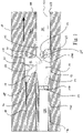
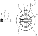
- FIG. 1 and 2 show a traction head 10 according to the invention as part of a laying system for a pipeline in the ground from a starting point to a destination along a predetermined laying line, in particular when laying pipelines near the surface in the form of underground cables or underground lines in the ground with a connection 11 for drill pipes 110 and a connection 12 for protective tubes 120.
- a device e.g. a drilling device
- an opening e.g. borehole 100
- a compression ring 130 for introducing mortar 140 is arranged between the protective tube 120 and the connection 12 .
- the drill pipes 110 or protective pipes 120 can be connected by welding or screw connections.
- the grouting ring 130 is connected to a grouting line 131 via which the mortar 140 is fed to the grouting ring 130 .
- the drill pipe 110 is located in a borehole 100 that is driven into the ground 101 with a drilling device (not shown).
- the pulling head 10 has a housing 13 which has a conical section 14 in order to compensate for the difference in diameter between the drill pipe 110 and the protective pipe 120 .
- the overcut area 102 which inevitably arises due to the different diameters of the drill pipes 110 and protective pipes 120, is filled with the mortar 140 via the grouting ring 130 behind the pulling head.
- a displacement element 15 is arranged on the housing 13 .
- the displacement element 15 acts here like a sword or plough, which, when the pulling head 10 is moved through the borehole 100 in the direction of the arrow A, creates a temporary opening in the ground 101 into which a route tape 200 can be inserted.
- the displacement element 15 is arranged on the housing 13 with its inner end 16 .
- the inner end 16 can be attached to the housing 13, for example, by welding or by a screw connection.
- the displacement element 15 has an outer end 17 .
- the length of the displacement element 15 is provided in such a way that the outer end 17 remains in the base 101 .
- the displacement element 15 has a discharge opening 19 on its rear side 18 .
- the discharge opening 19 is connected to a guide 20 which extends through the displacement element 15 into the housing 13, for example in the form of a channel.
- the guide 20 has a feed opening 21 .
- the route tape 200 is fed to the guide 20 via the feed opening 21 .
- the road tape 200 is fed through the inner space 22 of the guide 20 to the discharge opening 19 and discharged from there into the temporary opening in the floor 101 .
- the distance between the route strip 200 that has been laid and the protective tube 120 can be adjusted by changing the length of the displacement element 15 .
- displacement elements 15 of different lengths or spacers (not shown) can be provided.
- a memory 23 which is here a drum 24 which is arranged rotatably on an axis 25, the road tape is reeled.
- the line strip 200 is unwound from the drum 24 and fed through the guide 20 and the delivery opening 19 to the temporary opening in the floor 101 above the protective tubes 120 .
- the storage 23 can also be provided at the starting point and the line strip 200 can then be fed to the guide 20 either through the protective tube 120 or the drill tube 110 .
- the route tape 200 is introduced into the ground 101 while the protective pipe 120 and thus the pipeline are being installed, it is also possible to insert the route tape 200 while the opening is being created in the ground 101, for example during of drilling.
- the displacement element 15 described can be arranged, for example, directly on a drilling device or on or in the drill pipe string as such or also on the pipeline itself. This would be the case, for example, with microtunneling or when using the direct pipe method.
Landscapes
- Excavating Of Shafts Or Tunnels (AREA)
- Lining Or Joining Of Plastics Or The Like (AREA)
Priority Applications (1)
| Application Number | Priority Date | Filing Date | Title |
|---|---|---|---|
| EP22178421.8A EP4099525B1 (de) | 2016-07-07 | 2017-07-07 | Vorrichtung und verfahren zum einbringen einer zusatzeinrichtung in den boden |
Applications Claiming Priority (1)
| Application Number | Priority Date | Filing Date | Title |
|---|---|---|---|
| DE102016008203.8A DE102016008203A1 (de) | 2016-07-07 | 2016-07-07 | Vorrichtung und Verfahren zum Einbringen von Trassenband in den Boden |
Related Child Applications (1)
| Application Number | Title | Priority Date | Filing Date |
|---|---|---|---|
| EP22178421.8A Division EP4099525B1 (de) | 2016-07-07 | 2017-07-07 | Vorrichtung und verfahren zum einbringen einer zusatzeinrichtung in den boden |
Publications (2)
| Publication Number | Publication Date |
|---|---|
| EP3267540A1 EP3267540A1 (de) | 2018-01-10 |
| EP3267540B1 true EP3267540B1 (de) | 2022-06-22 |
Family
ID=59387871
Family Applications (2)
| Application Number | Title | Priority Date | Filing Date |
|---|---|---|---|
| EP17180330.7A Active EP3267540B1 (de) | 2016-07-07 | 2017-07-07 | Vorrichtung und verfahren zum einbringen von trassenband in den boden |
| EP22178421.8A Active EP4099525B1 (de) | 2016-07-07 | 2017-07-07 | Vorrichtung und verfahren zum einbringen einer zusatzeinrichtung in den boden |
Family Applications After (1)
| Application Number | Title | Priority Date | Filing Date |
|---|---|---|---|
| EP22178421.8A Active EP4099525B1 (de) | 2016-07-07 | 2017-07-07 | Vorrichtung und verfahren zum einbringen einer zusatzeinrichtung in den boden |
Country Status (6)
| Country | Link |
|---|---|
| EP (2) | EP3267540B1 (pl) |
| DE (1) | DE102016008203A1 (pl) |
| DK (1) | DK3267540T3 (pl) |
| ES (2) | ES2928376T3 (pl) |
| PL (2) | PL3267540T3 (pl) |
| PT (1) | PT3267540T (pl) |
Citations (1)
| Publication number | Priority date | Publication date | Assignee | Title |
|---|---|---|---|---|
| GB2259103A (en) * | 1991-08-30 | 1993-03-03 | Compair Holman Ltd | Improved drilling apparatus |
Family Cites Families (6)
| Publication number | Priority date | Publication date | Assignee | Title |
|---|---|---|---|---|
| DE3335561A1 (de) | 1983-09-30 | 1985-05-02 | Rastra AG, Pfäffikon, Freienbach | Verfahren zur herstellung von leichtbeton |
| DE3335651C2 (de) * | 1983-09-30 | 1986-01-30 | Josef 8490 Cham Schmidbauer | Für Kabelpflüge dienende Lenkvorrichtung für Warnbänder |
| FR2627025B1 (fr) * | 1988-02-10 | 1991-05-24 | Plymouth Francaise Sa | Dispositif avertisseur de canalisations enterrees |
| DE19623922C1 (de) | 1996-06-15 | 1998-02-12 | Foeckersperger Georg Gmbh | Anordnung zum Einziehen eines Rohres in den Erdboden, sowie Anwendung einer solchen Anordnung |
| DE19928682C2 (de) * | 1999-06-23 | 2001-09-20 | Foeckersperger Georg Gmbh | Anordnung und Verfahren zum Einführen eines Rohres in den Erdboden |
| AT509086B1 (de) * | 2010-01-21 | 2011-06-15 | Pichler Jan Michael | Verfahren und vorrichtung zur einbringung eines rohres für optische kabel in einen festen verlegegrund |
-
2016
- 2016-07-07 DE DE102016008203.8A patent/DE102016008203A1/de not_active Withdrawn
-
2017
- 2017-07-07 EP EP17180330.7A patent/EP3267540B1/de active Active
- 2017-07-07 DK DK17180330.7T patent/DK3267540T3/da active
- 2017-07-07 PT PT171803307T patent/PT3267540T/pt unknown
- 2017-07-07 PL PL17180330.7T patent/PL3267540T3/pl unknown
- 2017-07-07 PL PL22178421.8T patent/PL4099525T3/pl unknown
- 2017-07-07 EP EP22178421.8A patent/EP4099525B1/de active Active
- 2017-07-07 ES ES17180330T patent/ES2928376T3/es active Active
- 2017-07-07 ES ES22178421T patent/ES2987129T3/es active Active
Patent Citations (1)
| Publication number | Priority date | Publication date | Assignee | Title |
|---|---|---|---|---|
| GB2259103A (en) * | 1991-08-30 | 1993-03-03 | Compair Holman Ltd | Improved drilling apparatus |
Also Published As
| Publication number | Publication date |
|---|---|
| DE102016008203A1 (de) | 2018-01-11 |
| DK3267540T3 (da) | 2022-09-26 |
| PL3267540T3 (pl) | 2022-12-05 |
| ES2987129T3 (es) | 2024-11-13 |
| PL4099525T3 (pl) | 2024-07-15 |
| EP4099525A1 (de) | 2022-12-07 |
| EP4099525C0 (de) | 2024-04-10 |
| PT3267540T (pt) | 2022-09-16 |
| EP4099525B1 (de) | 2024-04-10 |
| ES2928376T3 (es) | 2022-11-17 |
| EP3267540A1 (de) | 2018-01-10 |
Similar Documents
| Publication | Publication Date | Title |
|---|---|---|
| DE69534139T2 (de) | Installation von Kabelkanälen | |
| DE202016008021U1 (de) | System zum oberflächennahen Verlegen von Erdkabeln oder Erdleitungen im Boden | |
| DE69500908T2 (de) | Verfahren und Vorrichtung zum Verlegen eines unterirdischen Fernmeldekabels | |
| EP0993540B1 (de) | Vorrichtung und verfahren zum herstellen von bohrlochverzweigungen | |
| DE69911810T2 (de) | VERFAHREN UND VORRICHTUNG ZUR HANDHABUNG VON BOHRLOCHGESTäNGEN | |
| DE3801824C1 (en) | Method and apparatus for the trenchless laying of supply lines | |
| DE3228684A1 (de) | Vorrichtung zum vorpressen kleiner, nicht mehr begehbarer rohre | |
| EP4099525B1 (de) | Vorrichtung und verfahren zum einbringen einer zusatzeinrichtung in den boden | |
| DE3501215C2 (pl) | ||
| EP3029262A1 (de) | Bohrgestänge, verbindungssystem, erdbohrvorrichtung und verfahren zum verbinden eines bohrgestängeschusses | |
| WO2003006786A1 (de) | Verfahren zum herstellen von erdbohrungen | |
| EP1635098B1 (de) | Verfahren und Spülkopf zum Freilegen von im Erdreich verlegten Anlagen | |
| EP0583650B1 (de) | Verfahren und Vorrichtung zur unterirdischen Einbringung von Transportrohren grösserer Länge in das Erdreich | |
| DE19825582C2 (de) | Vorrichtung zum grabenlosen Neuverlegen von insbesondere Trinkwasserrohren | |
| DE102007050931B4 (de) | Überbohrkopf zum Verdrängen des eine Leitung umgebenden Erdreiches und Verfahren zum Überbohren | |
| EP2150674B1 (de) | Verfahren und vorrichtung zur überprüfung der umhüllung einer rohrleitung während des einzugs in ein mit flüssigkeit gefülltes bohrloch | |
| EP2205813B1 (de) | Verfahren und vorrichtung zur überprüfung der umhüllung einer rohrleitung während der verlegung in ein mit flüssigkeit gefülltes bohrloch | |
| AT357946B (de) | Vorrichtung zum vortrieb eines aus mindestens einem rohrabschnitt bestehenden rohres im erdboden | |
| DE102014100490A1 (de) | Verfahren und System zum Verlegen von vor mechanischen Beanspruchungen geschützten Leitungen | |
| EP3663504B1 (de) | Erdbauverfahren, erdbauvorrichtung und erdbauinstallation | |
| DE19929893C2 (de) | Verfahren zum grabenlosen Verlegen von Rohrleitungen und Kabeln | |
| DE102011110622A1 (de) | Verfahren und Vorrichtungen zur Verlegung von zwei Rohrleitungen im Boden | |
| DE10114625A1 (de) | Vorrichtung, Verfahren und Verlegeeinrichtung zur hydraulischen Stützung eines Tunnels | |
| DE1809311A1 (de) | Verfahren und Vorrichtung zum Verlegen biegsamer Rohre oder Kabel | |
| WO2001025677A1 (de) | Schutzmantelerzeugung beim verlegen von leitungen |
Legal Events
| Date | Code | Title | Description |
|---|---|---|---|
| PUAI | Public reference made under article 153(3) epc to a published international application that has entered the european phase |
Free format text: ORIGINAL CODE: 0009012 |
|
| STAA | Information on the status of an ep patent application or granted ep patent |
Free format text: STATUS: THE APPLICATION HAS BEEN PUBLISHED |
|
| AK | Designated contracting states |
Kind code of ref document: A1 Designated state(s): AL AT BE BG CH CY CZ DE DK EE ES FI FR GB GR HR HU IE IS IT LI LT LU LV MC MK MT NL NO PL PT RO RS SE SI SK SM TR |
|
| AX | Request for extension of the european patent |
Extension state: BA ME |
|
| STAA | Information on the status of an ep patent application or granted ep patent |
Free format text: STATUS: REQUEST FOR EXAMINATION WAS MADE |
|
| 17P | Request for examination filed |
Effective date: 20180703 |
|
| RBV | Designated contracting states (corrected) |
Designated state(s): AL AT BE BG CH CY CZ DE DK EE ES FI FR GB GR HR HU IE IS IT LI LT LU LV MC MK MT NL NO PL PT RO RS SE SI SK SM TR |
|
| STAA | Information on the status of an ep patent application or granted ep patent |
Free format text: STATUS: EXAMINATION IS IN PROGRESS |
|
| 17Q | First examination report despatched |
Effective date: 20190926 |
|
| GRAP | Despatch of communication of intention to grant a patent |
Free format text: ORIGINAL CODE: EPIDOSNIGR1 |
|
| STAA | Information on the status of an ep patent application or granted ep patent |
Free format text: STATUS: GRANT OF PATENT IS INTENDED |
|
| INTG | Intention to grant announced |
Effective date: 20220105 |
|
| GRAS | Grant fee paid |
Free format text: ORIGINAL CODE: EPIDOSNIGR3 |
|
| GRAA | (expected) grant |
Free format text: ORIGINAL CODE: 0009210 |
|
| STAA | Information on the status of an ep patent application or granted ep patent |
Free format text: STATUS: THE PATENT HAS BEEN GRANTED |
|
| AK | Designated contracting states |
Kind code of ref document: B1 Designated state(s): AL AT BE BG CH CY CZ DE DK EE ES FI FR GB GR HR HU IE IS IT LI LT LU LV MC MK MT NL NO PL PT RO RS SE SI SK SM TR |
|
| REG | Reference to a national code |
Ref country code: GB Ref legal event code: FG4D Free format text: NOT ENGLISH |
|
| REG | Reference to a national code |
Ref country code: CH Ref legal event code: EP |
|
| REG | Reference to a national code |
Ref country code: DE Ref legal event code: R096 Ref document number: 502017013349 Country of ref document: DE |
|
| REG | Reference to a national code |
Ref country code: AT Ref legal event code: REF Ref document number: 1500404 Country of ref document: AT Kind code of ref document: T Effective date: 20220715 |
|
| REG | Reference to a national code |
Ref country code: IE Ref legal event code: FG4D Free format text: LANGUAGE OF EP DOCUMENT: GERMAN |
|
| REG | Reference to a national code |
Ref country code: PT Ref legal event code: SC4A Ref document number: 3267540 Country of ref document: PT Date of ref document: 20220916 Kind code of ref document: T Free format text: AVAILABILITY OF NATIONAL TRANSLATION Effective date: 20220912 |
|
| REG | Reference to a national code |
Ref country code: DK Ref legal event code: T3 Effective date: 20220919 |
|
| REG | Reference to a national code |
Ref country code: NL Ref legal event code: FP |
|
| REG | Reference to a national code |
Ref country code: LT Ref legal event code: MG9D |
|
| PG25 | Lapsed in a contracting state [announced via postgrant information from national office to epo] |
Ref country code: SE Free format text: LAPSE BECAUSE OF FAILURE TO SUBMIT A TRANSLATION OF THE DESCRIPTION OR TO PAY THE FEE WITHIN THE PRESCRIBED TIME-LIMIT Effective date: 20220622 Ref country code: NO Free format text: LAPSE BECAUSE OF FAILURE TO SUBMIT A TRANSLATION OF THE DESCRIPTION OR TO PAY THE FEE WITHIN THE PRESCRIBED TIME-LIMIT Effective date: 20220922 Ref country code: LT Free format text: LAPSE BECAUSE OF FAILURE TO SUBMIT A TRANSLATION OF THE DESCRIPTION OR TO PAY THE FEE WITHIN THE PRESCRIBED TIME-LIMIT Effective date: 20220622 Ref country code: HR Free format text: LAPSE BECAUSE OF FAILURE TO SUBMIT A TRANSLATION OF THE DESCRIPTION OR TO PAY THE FEE WITHIN THE PRESCRIBED TIME-LIMIT Effective date: 20220622 Ref country code: GR Free format text: LAPSE BECAUSE OF FAILURE TO SUBMIT A TRANSLATION OF THE DESCRIPTION OR TO PAY THE FEE WITHIN THE PRESCRIBED TIME-LIMIT Effective date: 20220923 Ref country code: FI Free format text: LAPSE BECAUSE OF FAILURE TO SUBMIT A TRANSLATION OF THE DESCRIPTION OR TO PAY THE FEE WITHIN THE PRESCRIBED TIME-LIMIT Effective date: 20220622 Ref country code: BG Free format text: LAPSE BECAUSE OF FAILURE TO SUBMIT A TRANSLATION OF THE DESCRIPTION OR TO PAY THE FEE WITHIN THE PRESCRIBED TIME-LIMIT Effective date: 20220922 |
|
| REG | Reference to a national code |
Ref country code: ES Ref legal event code: FG2A Ref document number: 2928376 Country of ref document: ES Kind code of ref document: T3 Effective date: 20221117 |
|
| PG25 | Lapsed in a contracting state [announced via postgrant information from national office to epo] |
Ref country code: RS Free format text: LAPSE BECAUSE OF FAILURE TO SUBMIT A TRANSLATION OF THE DESCRIPTION OR TO PAY THE FEE WITHIN THE PRESCRIBED TIME-LIMIT Effective date: 20220622 Ref country code: LV Free format text: LAPSE BECAUSE OF FAILURE TO SUBMIT A TRANSLATION OF THE DESCRIPTION OR TO PAY THE FEE WITHIN THE PRESCRIBED TIME-LIMIT Effective date: 20220622 |
|
| PG25 | Lapsed in a contracting state [announced via postgrant information from national office to epo] |
Ref country code: SM Free format text: LAPSE BECAUSE OF FAILURE TO SUBMIT A TRANSLATION OF THE DESCRIPTION OR TO PAY THE FEE WITHIN THE PRESCRIBED TIME-LIMIT Effective date: 20220622 Ref country code: SK Free format text: LAPSE BECAUSE OF FAILURE TO SUBMIT A TRANSLATION OF THE DESCRIPTION OR TO PAY THE FEE WITHIN THE PRESCRIBED TIME-LIMIT Effective date: 20220622 Ref country code: RO Free format text: LAPSE BECAUSE OF FAILURE TO SUBMIT A TRANSLATION OF THE DESCRIPTION OR TO PAY THE FEE WITHIN THE PRESCRIBED TIME-LIMIT Effective date: 20220622 Ref country code: EE Free format text: LAPSE BECAUSE OF FAILURE TO SUBMIT A TRANSLATION OF THE DESCRIPTION OR TO PAY THE FEE WITHIN THE PRESCRIBED TIME-LIMIT Effective date: 20220622 Ref country code: CZ Free format text: LAPSE BECAUSE OF FAILURE TO SUBMIT A TRANSLATION OF THE DESCRIPTION OR TO PAY THE FEE WITHIN THE PRESCRIBED TIME-LIMIT Effective date: 20220622 |
|
| PG25 | Lapsed in a contracting state [announced via postgrant information from national office to epo] |
Ref country code: IS Free format text: LAPSE BECAUSE OF FAILURE TO SUBMIT A TRANSLATION OF THE DESCRIPTION OR TO PAY THE FEE WITHIN THE PRESCRIBED TIME-LIMIT Effective date: 20221022 |
|
| REG | Reference to a national code |
Ref country code: DE Ref legal event code: R097 Ref document number: 502017013349 Country of ref document: DE |
|
| PG25 | Lapsed in a contracting state [announced via postgrant information from national office to epo] |
Ref country code: MC Free format text: LAPSE BECAUSE OF FAILURE TO SUBMIT A TRANSLATION OF THE DESCRIPTION OR TO PAY THE FEE WITHIN THE PRESCRIBED TIME-LIMIT Effective date: 20220622 Ref country code: AL Free format text: LAPSE BECAUSE OF FAILURE TO SUBMIT A TRANSLATION OF THE DESCRIPTION OR TO PAY THE FEE WITHIN THE PRESCRIBED TIME-LIMIT Effective date: 20220622 |
|
| PG25 | Lapsed in a contracting state [announced via postgrant information from national office to epo] |
Ref country code: LU Free format text: LAPSE BECAUSE OF NON-PAYMENT OF DUE FEES Effective date: 20220707 |
|
| PLBE | No opposition filed within time limit |
Free format text: ORIGINAL CODE: 0009261 |
|
| STAA | Information on the status of an ep patent application or granted ep patent |
Free format text: STATUS: NO OPPOSITION FILED WITHIN TIME LIMIT |
|
| 26N | No opposition filed |
Effective date: 20230323 |
|
| PG25 | Lapsed in a contracting state [announced via postgrant information from national office to epo] |
Ref country code: SI Free format text: LAPSE BECAUSE OF FAILURE TO SUBMIT A TRANSLATION OF THE DESCRIPTION OR TO PAY THE FEE WITHIN THE PRESCRIBED TIME-LIMIT Effective date: 20220622 |
|
| PG25 | Lapsed in a contracting state [announced via postgrant information from national office to epo] |
Ref country code: HU Free format text: LAPSE BECAUSE OF FAILURE TO SUBMIT A TRANSLATION OF THE DESCRIPTION OR TO PAY THE FEE WITHIN THE PRESCRIBED TIME-LIMIT; INVALID AB INITIO Effective date: 20170707 |
|
| PG25 | Lapsed in a contracting state [announced via postgrant information from national office to epo] |
Ref country code: MK Free format text: LAPSE BECAUSE OF FAILURE TO SUBMIT A TRANSLATION OF THE DESCRIPTION OR TO PAY THE FEE WITHIN THE PRESCRIBED TIME-LIMIT Effective date: 20220622 Ref country code: CY Free format text: LAPSE BECAUSE OF FAILURE TO SUBMIT A TRANSLATION OF THE DESCRIPTION OR TO PAY THE FEE WITHIN THE PRESCRIBED TIME-LIMIT Effective date: 20220622 |
|
| PG25 | Lapsed in a contracting state [announced via postgrant information from national office to epo] |
Ref country code: TR Free format text: LAPSE BECAUSE OF FAILURE TO SUBMIT A TRANSLATION OF THE DESCRIPTION OR TO PAY THE FEE WITHIN THE PRESCRIBED TIME-LIMIT Effective date: 20220622 |
|
| PG25 | Lapsed in a contracting state [announced via postgrant information from national office to epo] |
Ref country code: MT Free format text: LAPSE BECAUSE OF FAILURE TO SUBMIT A TRANSLATION OF THE DESCRIPTION OR TO PAY THE FEE WITHIN THE PRESCRIBED TIME-LIMIT Effective date: 20220622 |
|
| PG25 | Lapsed in a contracting state [announced via postgrant information from national office to epo] |
Ref country code: BG Free format text: LAPSE BECAUSE OF FAILURE TO SUBMIT A TRANSLATION OF THE DESCRIPTION OR TO PAY THE FEE WITHIN THE PRESCRIBED TIME-LIMIT Effective date: 20220622 |
|
| PG25 | Lapsed in a contracting state [announced via postgrant information from national office to epo] |
Ref country code: BG Free format text: LAPSE BECAUSE OF FAILURE TO SUBMIT A TRANSLATION OF THE DESCRIPTION OR TO PAY THE FEE WITHIN THE PRESCRIBED TIME-LIMIT Effective date: 20220622 |
|
| PGFP | Annual fee paid to national office [announced via postgrant information from national office to epo] |
Ref country code: NL Payment date: 20250721 Year of fee payment: 9 |
|
| PGFP | Annual fee paid to national office [announced via postgrant information from national office to epo] |
Ref country code: ES Payment date: 20250826 Year of fee payment: 9 |
|
| PGFP | Annual fee paid to national office [announced via postgrant information from national office to epo] |
Ref country code: DK Payment date: 20250725 Year of fee payment: 9 Ref country code: DE Payment date: 20250505 Year of fee payment: 9 |
|
| PGFP | Annual fee paid to national office [announced via postgrant information from national office to epo] |
Ref country code: IT Payment date: 20250724 Year of fee payment: 9 |
|
| PGFP | Annual fee paid to national office [announced via postgrant information from national office to epo] |
Ref country code: GB Payment date: 20250722 Year of fee payment: 9 Ref country code: BE Payment date: 20250721 Year of fee payment: 9 |
|
| PGFP | Annual fee paid to national office [announced via postgrant information from national office to epo] |
Ref country code: AT Payment date: 20250722 Year of fee payment: 9 Ref country code: FR Payment date: 20250725 Year of fee payment: 9 |
|
| PGFP | Annual fee paid to national office [announced via postgrant information from national office to epo] |
Ref country code: CH Payment date: 20250801 Year of fee payment: 9 |
|
| PGFP | Annual fee paid to national office [announced via postgrant information from national office to epo] |
Ref country code: IE Payment date: 20250723 Year of fee payment: 9 |
|
| PGFP | Annual fee paid to national office [announced via postgrant information from national office to epo] |
Ref country code: PL Payment date: 20260625 Year of fee payment: 10 |
|
| PGFP | Annual fee paid to national office [announced via postgrant information from national office to epo] |
Ref country code: PT Payment date: 20260619 Year of fee payment: 10 |
|
| REG | Reference to a national code |
Ref country code: CH Ref legal event code: U11 Free format text: ST27 STATUS EVENT CODE: U-0-0-U10-U11 (AS PROVIDED BY THE NATIONAL OFFICE) Effective date: 20260801 |