EP3263419B1 - Verfahren zur höhensteuerung eines transportfahrzeugs, und entsprechendes transportfahrzeug - Google Patents
Verfahren zur höhensteuerung eines transportfahrzeugs, und entsprechendes transportfahrzeug Download PDFInfo
- Publication number
- EP3263419B1 EP3263419B1 EP17177240.3A EP17177240A EP3263419B1 EP 3263419 B1 EP3263419 B1 EP 3263419B1 EP 17177240 A EP17177240 A EP 17177240A EP 3263419 B1 EP3263419 B1 EP 3263419B1
- Authority
- EP
- European Patent Office
- Prior art keywords
- height
- suspension
- bogie
- shaft
- axle
- Prior art date
- Legal status (The legal status is an assumption and is not a legal conclusion. Google has not performed a legal analysis and makes no representation as to the accuracy of the status listed.)
- Active
Links
Images


Classifications
-
- B—PERFORMING OPERATIONS; TRANSPORTING
- B61—RAILWAYS
- B61F—RAIL VEHICLE SUSPENSIONS, e.g. UNDERFRAMES, BOGIES OR ARRANGEMENTS OF WHEEL AXLES; RAIL VEHICLES FOR USE ON TRACKS OF DIFFERENT WIDTH; PREVENTING DERAILING OF RAIL VEHICLES; WHEEL GUARDS, OBSTRUCTION REMOVERS OR THE LIKE FOR RAIL VEHICLES
- B61F5/00—Constructional details of bogies; Connections between bogies and vehicle underframes; Arrangements or devices for adjusting or allowing self-adjustment of wheel axles or bogies when rounding curves
-
- B—PERFORMING OPERATIONS; TRANSPORTING
- B61—RAILWAYS
- B61F—RAIL VEHICLE SUSPENSIONS, e.g. UNDERFRAMES, BOGIES OR ARRANGEMENTS OF WHEEL AXLES; RAIL VEHICLES FOR USE ON TRACKS OF DIFFERENT WIDTH; PREVENTING DERAILING OF RAIL VEHICLES; WHEEL GUARDS, OBSTRUCTION REMOVERS OR THE LIKE FOR RAIL VEHICLES
- B61F5/00—Constructional details of bogies; Connections between bogies and vehicle underframes; Arrangements or devices for adjusting or allowing self-adjustment of wheel axles or bogies when rounding curves
- B61F5/02—Arrangements permitting limited transverse relative movements between vehicle underframe or bolster and bogie; Connections between underframes and bogies
-
- B—PERFORMING OPERATIONS; TRANSPORTING
- B61—RAILWAYS
- B61F—RAIL VEHICLE SUSPENSIONS, e.g. UNDERFRAMES, BOGIES OR ARRANGEMENTS OF WHEEL AXLES; RAIL VEHICLES FOR USE ON TRACKS OF DIFFERENT WIDTH; PREVENTING DERAILING OF RAIL VEHICLES; WHEEL GUARDS, OBSTRUCTION REMOVERS OR THE LIKE FOR RAIL VEHICLES
- B61F1/00—Underframes
- B61F1/08—Details
- B61F1/14—Attaching or supporting vehicle body-structure
Definitions
- a vehicle In the rail passenger transport sector, a vehicle is required to make several stops in stations, or stations, to allow the exit or entry of travelers.
- Passengers' access to a car takes place at the level of the floor of the car, which is generally placed opposite the station platform.
- the difference in heights, which may exist between the floor and the platform, may prove to be unacceptable for certain users, in particular those with reduced mobility.
- the ADA standard for American Disability Act, imposes a height difference between the dock and the floor of less than 16 mm.
- the document DE 10 236 246 B4 offers a solution to adjust the height of the floor, so that it is at the same height as that of the platform. A similar solution is proposed by the document DE 19647998 A1 .
- An object of the invention is therefore to propose a method making it possible to modify in a simple manner the height of a transport vehicle, in particular to ensure easy access to the users of this vehicle, during its various stops in a station.
- the subject of the invention is a method for controlling the height of a transport vehicle as defined in claim 1.
- the invention relates, according to a second aspect, to a transport vehicle as defined in claim 9.
- a passenger transport vehicle car 10 is illustrated, in section, in a simplified manner on the figure. figure 1 .
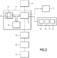
- a partial drawing of car 10 is shown on the figure 2 .
- Such a transport vehicle is, for example, a bus, a trolleybus, a tram, a metro, a train or any other type of railway vehicle.
- the vehicle is able to stop at a station comprising a platform 12.
- the platform 12 has a height H pla , defined from the top of rails 11 on which the vehicle is traveling.
- the car 10 comprises a floor 14 for passenger access to a body 16 and at least one bogie 18.
- the vehicle comprises several cars 10 and several bogies 18 distributed along the vehicle.
- each car 10 includes two bogies 18.
- the bogie 18 comprises an axle 20, a bogie frame 21, at least one primary suspension 22 interposed between the axle 20 and the bogie frame 21, and at least one secondary suspension 24 interposed between the primary suspension 22 and the floor 14.
- the bogie 18 comprises two primary suspensions 22 and two secondary suspensions 24.
- the axle 20 is rotatable relative to the bogie frame 21 along an axis substantially parallel to the ground, the axis being transverse to the rails 11.
- the axle 20 comprises two wheels 26 and a shaft 28 connecting the wheels 26.
- the wheels 26 are, for example, solid wheels intended to cooperate with the rails 11, or wheels fitted with tires.
- the wheels 26 of the vehicle are solid wheels.
- the shaft 28 of the axle 20 has a height R defined from the rails 11. More precisely, the height considered is, for example, the height of the upper part of the shaft 28 defined from the top of the rails 11. This height R depends on the characteristics of the wheels 26.
- the wheels 26 have a wear which depends on the number of kilometers traveled by the vehicle. This wear deforms the wheels 26 in a non-uniform manner which reduces the grip and therefore the safety of the passengers.
- the vehicle is usually taken to a maintenance center in which control operations are carried out on the vehicle. These control operations are for example maintenance operations.
- the vehicle is advantageously required to receive these control operations several times during its lifetime. It should be noted that the components of the vehicle received a first control operation during their construction.
- these checking operations may include the replacement of the tires.
- these control operations include, for example, an operation of reprofiling the wheels 26, during which the wheels 26 are machined to give them a shape. standardized.
- each wheel exhibits a shrinkage of material of predetermined thickness.
- This material shrinkage thickness is possibly different for each wheel of the vehicle, in order to guarantee perfect symmetry between the wheels of the same axle and between the different axles of the vehicle.
- the shaft 28 of the axle 20 thus loses height.
- the total height lost by the shaft 28 during all the reprofiling operations carried out on the wheels 26 since the construction of the wheels 26 is denoted ⁇ repro .
- the characteristic parameter R 0 is for example equal to the height of the shaft 28 defined from the top of the rails 11 measured at the end of the last checking operation. This height is advantageously measured by an operator at the end of each control operation.
- the vehicle comprises its own traction / braking software, when it is executed, to calculate the diameter of the wheels of each axle from the measured speed of this axle and thus to calculate the height R.
- reprofiling compensating shims 29A of thickness ⁇ shims / repro .
- these reprofiling compensation wedges 29A also compensate for the wear of the wheels 26 observed between two reprofiling operations.
- the thickness of the reprofiling compensation shims 29A ⁇ shims / repro is for example equal to the sum of the total height lost by the shaft 28 during all the reprofiling operations undergone by the wheels 26, and the height lost by the shaft 28 associated with the wear of the wheels 26 observed between each reprofiling operations since the construction of the wheels 26.
- the reprofiling compensation wedges 29A are placed, for example, under the secondary suspension 24 and on the bogie frame 21.
- the bogie frame 21 then comprises the reprofiling compensation wedges 29A.
- the control operations also include, for example, an estimate of the creep ⁇ creep of the primary suspension 22. This is in particular the case when the primary suspension 22 comprises elements made of elastomeric material.
- the creep is then evaluated by an operator and possibly compensated by the addition of creep compensation shims 29B of thickness ⁇ wedges / creep .
- the thickness ⁇ shims / creep of the creep compensation shims 29B is equal to the creep ⁇ creep .
- the creep compensation wedges 29B are placed, for example, under the secondary suspension 24 and on the bogie frame 21.
- the bogie frame 21 then comprises the creep compensation wedges 29B.
- the bogie frame 21 comprises a cross member 21A which rests on the primary suspension 22.
- the top of the bogie frame 21 is defined as the upper wall of the cross member 21A in line with the primary suspension 22.
- the bogie frame 21 In line with the primary suspension 22, the bogie frame 21 has a thickness H c .
- This thickness H c is, for example, equal to the nominal construction thickness H cn of the bogie frame 21 measured in line with the primary suspension 22.
- the bogie frame 21 comprises, for example, other components such as calibration wedges (not shown).
- the thickness of these components, in particular of these shims, is then added to the nominal construction thickness H cn in the value of the thickness H c of the bogie frame 21.
- the primary suspension 22 comprises shock absorbers, not shown, and springs 30 to be chosen from the group comprising: pneumatic springs or metal springs.
- the springs 30 have the same stiffness K and are placed between the axle 20 and the bogie 18. Through the springs 30, the primary suspension 22 then has a stiffness K.
- the secondary suspension 24 extends from the top of the bogie frame 21.
- the secondary suspension 24 comprises for example at least one, or even more, pneumatic cushion (s) 36, a device 38 for actuating the secondary suspension 24, a compressed air tank 40 and a height sensor 42.
- the actuating device 38 is able to control the adjustment of the height of the secondary suspension 24. More precisely, the actuating device 38 is configured to increase or decrease the pressure in the air bag (s) ( s) 36, in controlling the supply of compressed air from the reservoir 40. The variation in pressure in the air bag (s) 36 modifies the height of the secondary suspension 24.
- the actuating device 38 is advantageously a solenoid valve.
- the secondary suspension 24 advantageously comprises a load sensor 32.
- the load sensor 32 is able to measure the load, denoted P, exerted by the body 16 on the bogie 18.
- the load P depends in particular on the mass of the passengers and the luggage. occupying the cash register 16.
- the load sensor 32 is, for example, able to measure the pressure of the pneumatic cushions 36.
- the load sensor 32 is able to deduce therefrom a measurement of the load P exerted by the body 16 on the bogie 18.
- the secondary suspension 24 advantageously comprises an average weighing valve intended to control the braking force of the vehicle.
- this average weighing valve is then the load sensor 32.
- the primary suspension 22 has a deflection under load equal to the ratio of the load Q on the primary suspension by the stiffness K of the springs 30.
- the load Q on the primary suspension is equal to the sum of the measured load P and the suspended mass. between the primary and secondary suspension stages.
- the mass suspended between the primary and secondary suspension stages has a predetermined value which depends on the configuration of the bogie.
- the primary suspension 22 thus has a height H p defined from the shaft 28 of the axle 20.
- the characteristic parameter H p0 depends on the nominal construction height H pn of the primary suspension 22 defined from the shaft 28, on the load P exerted by the body 16 on the bogie 18, on the stiffness K of the primary suspension 22 and creep ⁇ creep of the suspension
- the characteristic parameter H p0 is, for example, equal to the height of the primary suspension 22 defined from the shaft 28 for a reference load of the body 16, for example, when the body 16 is empty of passengers, that is to say when the body 16 is zero load. This height is advantageously measured by an operator at the end of each control operation.
- the primary suspension 22 comprises, for example, other components such as calibration wedges (not shown) intended to compensate for manufacturing tolerances in the components of the vehicle.
- the thickness of these components, in particular of these calibration shims, is then added to the expression for the parameter H p0 .
- H cb denotes the height of the top of the bogie frame 21 defined from the shaft 28. This height H cb then depends on the thickness H c of the bogie frame 21 measured in line with the primary suspension 22, from the height H p of the primary suspension 22 defined from the shaft 28, and possibly the thickness ⁇ shims / repro of the reprofiling compensation shims 29A and / or the thickness ⁇ shims / creep of the compensation shims creep 29B.
- the secondary suspension 24 has a height H s defined from the top of the bogie frame 21.
- the height sensor 42 is suitable for measuring this height H s .
- the floor 14 has, at the level of the bogie 18, a height H f defined from the top of the rails 11.
- the height H f of the floor 14 depends on the height R of the shaft 28 of the axle 20 defined from the top of the rails 11, on the height H cb of the top of the bogie frame 21 defined from the shaft 28, and the height H s of the secondary suspension 24 defined from the top of the bogie frame 21.
- the height H f also depends on a geometric constant H f0 depending on the geometry and the dimensions of the car 10.
- the constant H f0 is thus, for example, equal to the thickness of the floor 14 measured at the level of the secondary suspension. 24.
- H f R + H cb + H s + H f0 .
- the vehicle comprises a processing unit 44 and an odometer 46.
- the odometer 46 is able to calculate the number of kilometers traveled by the vehicle between two predetermined dates.
- the predetermined dates are, for example, the date of the last control operation and the current date.
- the odometer 46 comprises, for example, a processor 48 capable of managing the operation of the counter 46, a memory 50 capable of storing the number of kilometers traveled between the two predetermined dates, and a geolocation system 52, for example GPS type (Global Positioning System).
- the processor 48 is then connected to the memory 50 and to the geolocation system 52.
- the processing unit 44 is connected to the odometer 46, to the load sensor 32, to the displacement sensor 42 and to the device 38 for actuating the secondary suspension 24 of each bogie 18 of each car 10 of the vehicle.
- the processing unit 44 comprises a processor 54 connected to a memory 56 and to a graphic interface 58.
- the memory 56 is also able to store the number of kilometers traveled by the vehicle between the two predetermined dates.
- the graphical interface 58 is configured to allow an operator to store in the memory 56 the known values of the preceding characteristics.
- the memory 56 comprises a program 60.
- the program 60 is able to manage the steps of the method for controlling the position of the floor 14 of the car 10 of the vehicle, the processor 54 being able to carry out the calculations.
- the processor 54 is able to estimate the height R of the shaft 28 defined from the top of the rails 11.
- the processor 54 is able to take into account the wear of the wheels 26 in its calculation of the height R of the shaft 28 defined from the top of the rails 11.
- the processor 54 is able to calculate, from the data of the odometer 46, a theoretical wear of the wheels as a function of the number of kilometers traveled by the vehicle.
- the memory 56 comprises traction / braking software suitable for calculating the diameter of the wheels of each axle from the measured speed of this axle.
- the processor 54 is then able to deduce therefrom a theoretical reduction ⁇ wear / theo in the height of the shaft 28 associated with the wear.
- this theoretical reduction ⁇ wear / theo is equal to the effective reduction ⁇ wear .
- the processor 54 is also able to calculate the heights H p , H cb , H s and H f according to the preceding formulas, and to estimate the difference between the height H pla of the platform 12 and the height H f of the floor 14.
- the processor 54 is then able to control the device 38 for actuating the secondary suspension 24, so that the difference between the height H pla of the platform 12 and the height H f of the floor 14 is between -16mm and 16mm, advantageously in order to that this difference be canceled.
- the method is implemented for each bogie of each car of the vehicle.
- the method comprises a step 100 of parameterizing the processing unit 44, a step 102 of estimating the height of the top of the bogie frame 21 followed by a step 104 of estimating the height of the shaft 28 of the 'axle 20, a step 106 of measuring the height of the secondary suspension 24 and a step 108 of adjusting the height of the secondary suspension 24 as a function of the height of the platform 12 to position the floor at the height of the platform 12 .
- an operator measures and stores the known values of the previous characteristics of the platform 12 and of the vehicle, in the memory 56 of the processing unit 44.
- Step 102 for estimating the height of the top of the bogie frame 21 comprises a step 110 for estimating the height of the primary suspension 22.
- the step 110 for estimating the height of the primary suspension 22 comprises a step 120 of measuring the load of the body 16 on the bogie 18, during which the load sensor 32 measures the load P of the body 16 on the bogie 18.
- the load sensor 32 measures, for example, the pressure of the pneumatic cushions 36 and derives therefrom a measurement of the load P.
- the step 110 for estimating the height of the primary suspension 22 then comprises a step 122 for calculating the deflection under load of the primary suspension 22.
- the processor 54 calculates the deflection under load of the primary suspension 22, from the measurement of the load P carried out in the measurement step 120 of the load, of the mass between the primary and secondary suspension stage and of the stiffness stored by the memory 56. More precisely, the processor 54 realizes the sum of the measured load P and of the mass between the primary suspension stages and secondary and divide this sum by the stiffness K of the primary suspension 22.
- the stiffness K is, for example, equal to the stiffness of the springs 30.
- the step 110 for estimating the height of the primary suspension 22 then comprises a step 124 for calculating the height H p of the primary suspension 22 defined from the shaft 28.
- the processor 54 uses the calculation carried out in step 122 of calculating the deflection under load of the preceding primary suspension 22 to deduce therefrom the height H p of the primary suspension 22 defined from the shaft 28. More precisely, the processor 54 subtracts the characteristic parameter H p0 of the primary suspension 22 by the deflection calculated in step 122 of calculating the deflection under load of the primary suspension 22.
- Step 102 for estimating the height of the top of the bogie frame 21 comprises a step 125 for calculating the height of the bogie frame 21.
- the processor 54 attributes to the height H cb of the top of the bogie frame 21 defined from the shaft 28, the sum of the height H p of the primary suspension 22, of the thickness H c of the bogie frame 21, and possibly of the thickness ⁇ shims / repro of the reprofiling compensation shims 29A and / or of the thickness ⁇ shims / creep of the compensation shims of creep 29B.
- the thicknesses of the shims are added if the shims are present in the bogie 18.
- Step 104 of estimating the height of the shaft 28 of the axle 20 advantageously comprises a step 126 of estimating the theoretical wear of the wheels 26 as a function of the mileage.
- the processor 54 collects the number of kilometers traveled by the vehicle since the last check operation, from the odometer 46 or from the memory 56. The processor 54 then calculates the theoretical reduction ⁇ wear / theo of the height of the shaft 28 associated with the wear. Alternatively, the processor 54 retrieves the diameter of the wheel from the data transmitted by the traction / braking software and deduced therefrom the theoretical reduction ⁇ wear / theo of the height of the shaft 28.
- the height sensor 42 measures the height H s of the secondary suspension 24 defined from the top of the bogie frame 21.
- the step 108 for adjusting the height of the secondary suspension 24 comprises a first step 130 for calculating the height of the floor 14.
- the step 108 of adjusting the height of the secondary suspension 24 then comprises a step 132 of adjusting the height of the secondary suspension 24.
- the processor 54 calculates the difference between the height H f of the floor 14 defined from the top of the rails 11 and the height H pla of the platform 12 defined at from the top of the rails 11.
- the processor 54 thus determines the modification in height that the secondary suspension 24 must undergo so that the difference is between -16mm and 16mm, advantageously so that it is canceled.
- the processor 54 then prepares a command and sends it to the actuation device 38.
- the device 38 controls the supply of compressed air from the reservoir 40 to the pneumatic cushion (s) 36, and thus varies the volume of the cushion (s) tire (s) 36 and therefore the height of the secondary suspension 24.
- the processor 54 On the move, the processor 54 generates a command and sends it to the actuator 38 only when the secondary suspension height varies, for example, by more than 50 mm from a reference height of the secondary suspension.
- the aim here is to minimize air consumption in dynamic mode.
- the secondary suspension is readjusted to the reference height in order to be re-centered before the rolling phase.
- the adjustment of the height of the secondary suspension 24 is made according to the height of the primary suspension 22 and the height of the shaft 28 of the axle 20 from the top of the rails 11.
- the step 104 of estimating the height of the shaft 28 of the axle 20 is implemented before the step 102 of estimating the height of the top of the bogie frame 21.
- the method does not include a step 104 of estimating the height of the shaft 28 of the axle 20.
- the processor 54 assigns a constant value at the height R of the shaft 28 of the axle 20 defined from the top of the rails 11. This value is advantageously the height R 0 of the shaft 28 defined from the top of the rails 11 measured by a operator during the last check operation.
- the method described provides a solution for adjusting the height of the floor by taking into account the value of parameters such as the load of the vehicle or the wear of the wheels.
- the method thus makes it possible to modify in a simple manner the height of the transport vehicle in order to facilitate the access of all travelers to the body of the vehicle.
- the method makes it possible to comply with the ADA standard.
Landscapes
- Engineering & Computer Science (AREA)
- Mechanical Engineering (AREA)
- Vehicle Body Suspensions (AREA)
Claims (9)
- Verfahren zum Steuern der Position eines Bodens (14) eines Wagens (10) eines sich auf Schienen bewegenden Schienenfahrzeugs in Bezug auf einen Bahnsteig, wobei der Wagen einen Wagenkasten (16) und mindestens ein Drehgestell (18) umfasst und das Drehgestell (18) einen Radsatz (20), einen Rahmen (21), mindestens eine Primäraufhängung (22), die zwischen dem Radsatz (20) und dem Rahmen des Drehgestells (21) angeordnet ist, und mindestens eine Sekundäraufhängung (24), die zwischen der Primäraufhängung (22) und dem Boden (14) angeordnet ist, aufweist, wobei der Radsatz (20) durch eine Achse (28) verbundene Räder (26) umfasst, wobei das Verfahren die folgenden Schritte aufweist:- Messen (106) der Höhe (Hs) der Sekundäraufhängung (24), die ab der Spitze des Rahmens des Drehgestells (21) definiert ist, und- Einstellen (108) der Höhe (Hs) der Sekundäraufhängung (24) abhängig von der Höhe (Hpla) des Bahnsteigs (12), die ab dem Scheitelpunkt der Schienen (11) definiert ist, um den Boden (14) an die Höhe (Hpla) des Bahnsteigs (12) zu bringen,dadurch gekennzeichnet, dass das Verfahren einen Schritt (102) des Schätzens der Höhe (Hcb) der Spitze des Rahmens des Drehgestells, die ab der Achse (28) des Radsatzes (20) definiert ist, und einen Schritt (104) des Schätzens der Höhe (R) der Achse (28) des Radsatzes (20), die von dem Scheitelpunkt der Schienen (11) gemessen ist, umfasst,
wobei das Einstellen (108) der Höhe (HS) der Sekundäraufhängung (24) abhängig von der geschätzten Höhe (Hcb) der Spitze des Rahmens des Drehgestells (21), die ab der Achse (28) definiert ist, und abhängig von der geschätzten Höhe (R) der Achse (28), die ab dem Scheitelpunkt der Schienen (11) definiert ist, durchgeführt wird. - Verfahren nach Anspruch 1, bei dem der Schritt (102) des Schätzens der Höhe (Hcb) der Spitze des Rahmens des Drehgestells (21) einen Schritt (110) des Schätzens der Höhe (Hp) der Primäraufhängung (22), die ab der Achse (28) des Radsatzes (20) definiert ist, umfasst.
- Verfahren nach Anspruch 2, bei dem der Schritt (110) des Schätzens der Höhe (Hp) der Primäraufhängung (22) die folgenden Schritte umfasst:- Berechnen (122) der Auslenkung unter Last der Primäraufhängung (22) und- Berechnen (124) der Höhe (Hp) der Primäraufhängung (22) die ab der Achse (28) des Radsatzes (20) definiert ist, wobei diese Berechnung (124) die Subtraktion eines charakteristischen Parameters (Hp0) der Primäraufhängung (22) von der berechneten Auslenkung unter Last der Primäraufhängung (22) umfasst.
- Verfahren nach Anspruch 3, bei dem der charakteristische Parameter (Hp0) der Primäraufhängung (22) gleich der ab der Achse (28) der Primäraufhängung (22) definierten Höhe für eine Referenzbeladung des Wagenkastens (16) ist.
- Verfahren nach Anspruch 3 oder 4, bei dem der Schritt (110) des Schätzens der ab der Achse (28) des Radsatzes (20) definierten Höhe (Hp) der Primäraufhängung (22) einen Schritt (120) des Messens einer Last (P), die von dem Wagenkasten (16) auf das Drehgestell (18) ausgeübt wird, umfasst, wobei die Auslenkung unter Last der Primäraufhängung (22) gleich dem Verhältnis der Summe der gemessenen, von dem Wagenkasten (16) auf das Drehgestell (18) ausgeübten Last (P) und einer vorbestimmten Masse zwischen der Primäraufhängung und der Sekundäraufhängung zu der Steifigkeit (K) der Primäraufhängung ist.
- Verfahren nach Anspruch 5, bei dem die Sekundäraufhängung (24) mindestens ein pneumatisches Kissen (36) und einen Lastaufnehmer (32) umfasst, die geeignet sind, den Schritt (120) des Messens der Last (P) durchzuführen, wobei der Lastaufnehmer (32) geeignet ist, den Druck jedes pneumatischen Kissens (36) der Sekundäraufhängung (24) zu messen.
- Verfahren nach einem beliebigen der vorhergehenden Ansprüche, bei dem der Schritt (104) des Schätzens der Höhe (R) der Achse (28) des Radsatzes (20), der ab dem Scheitelpunkt der Schienen (11) definiert ist, die folgenden Schritte umfasst:- Schätzen (126) der theoretischen Abnutzung der Räder (26) und- Berechnen (128) der Höhe (R) der Achse (28), die ab dem Scheitelpunkt der Schienen (11) definiert ist, wobei diese Berechnung (128) die Subtraktion eines charakteristischen Parameters (R0) des Radsatzes (20) von einer theoretischen Verringerung (Δusure/theo) der Höhe der Achse 28, die der theoretischen Abnutzung der Räder (26) zugeordnet ist, umfasst.
- Verfahren nach Anspruch 7, bei dem das Fahrzeug mindestens einen Steuervorgang empfangen hat, wobei der charakteristische Parameter (R0) des Radsatzes (20) gleich der ab dem Scheitelpunkt der Schienen (11) definierten Höhe (R) der Achse (28) ist, die am Ende dieses Steuervorganges gemessenen wird.
- Transportfahrzeug, das mindestens einen Wagen (10) aufweist, der einen Boden (14), einen Wagenkasten (16) und mindestens ein Drehgestell (18) umfasst, wobei das Drehgestell (18) einen Radsatz (20), einen Rahmen des Drehgestells (21), mindestens eine Primäraufhängung (22), die zwischen dem Radsatzes (20) und dem Rahmen des Drehgestells (21) angeordnet ist, und mindestens eine Sekundäraufhängung (24), die zwischen der Primäraufhängung (22) und dem Boden (14) angeordnet ist, aufweist, wobei der Radsatz (20) durch eine Achse (28) verbundene Räder (26), wobei das Fahrzeug einen Höhensensor (42), eine Vorrichtung (38) zur Betätigung der sekundären Aufhängung (14) und einen Prozessor (54) einer Verarbeitungseinheit (44) aufweist, der die Durchführung des Verfahrens gemäß einem der vorhergehenden Ansprüche ermöglicht..
Applications Claiming Priority (1)
| Application Number | Priority Date | Filing Date | Title |
|---|---|---|---|
| FR1656120A FR3053301B1 (fr) | 2016-06-29 | 2016-06-29 | Procede de commande de la hauteur d'un vehicule de transport et vehicule de transport associe |
Publications (2)
| Publication Number | Publication Date |
|---|---|
| EP3263419A1 EP3263419A1 (de) | 2018-01-03 |
| EP3263419B1 true EP3263419B1 (de) | 2020-08-05 |
Family
ID=56842908
Family Applications (1)
| Application Number | Title | Priority Date | Filing Date |
|---|---|---|---|
| EP17177240.3A Active EP3263419B1 (de) | 2016-06-29 | 2017-06-21 | Verfahren zur höhensteuerung eines transportfahrzeugs, und entsprechendes transportfahrzeug |
Country Status (6)
| Country | Link |
|---|---|
| US (1) | US10787185B2 (de) |
| EP (1) | EP3263419B1 (de) |
| JP (1) | JP6894779B2 (de) |
| CA (1) | CA2971967C (de) |
| ES (1) | ES2824802T3 (de) |
| FR (1) | FR3053301B1 (de) |
Families Citing this family (10)
| Publication number | Priority date | Publication date | Assignee | Title |
|---|---|---|---|---|
| FR3084854B1 (fr) | 2018-08-09 | 2020-11-27 | Alstom Transp Tech | Procede de commande de la hauteur d'un vehicule et vehicule associe |
| CN109017819B (zh) * | 2018-08-29 | 2019-11-22 | 中车青岛四方机车车辆股份有限公司 | 高度调节系统及高度调节方法 |
| FR3085932B1 (fr) * | 2018-09-14 | 2021-07-23 | Speedinnov | Suspension pneumatique pour vehicule ferroviaire |
| US11904649B1 (en) * | 2018-10-05 | 2024-02-20 | Glydways, Inc. | Vehicle with independently adjustable suspension |
| FR3104525B1 (fr) * | 2019-12-17 | 2022-05-06 | Alstom Transp Tech | Bogie de véhicule ferroviaire |
| US12116025B2 (en) * | 2020-01-21 | 2024-10-15 | Alstom Transport Technologies | Method for controlling the vertical position of a vehicle and associated control assembly |
| FR3115886B1 (fr) | 2020-11-04 | 2022-12-09 | Alstom Transp Tech | Procédé de mesure d’une distance d’un véhicule à un quai |
| DE102022104793B3 (de) | 2022-03-01 | 2023-02-16 | Deutsches Zentrum für Luft- und Raumfahrt e.V. | Schienenfahrzeug |
| DE102022209423B3 (de) * | 2022-09-09 | 2024-01-18 | Siemens Mobility GmbH | Fahrwerkshöhenregelung mittels Fahrgasteinstiegssensor |
| CN118928490A (zh) * | 2024-09-03 | 2024-11-12 | 株洲时代新材料科技股份有限公司 | 一种列车车体高度调节方法 |
Family Cites Families (21)
| Publication number | Priority date | Publication date | Assignee | Title |
|---|---|---|---|---|
| US4798369A (en) * | 1987-11-03 | 1989-01-17 | The Firestone Tire & Rubber Company | Ultrasonic air spring system |
| JPH0347868U (de) * | 1989-09-20 | 1991-05-07 | ||
| JPH0757605B2 (ja) * | 1991-02-19 | 1995-06-21 | 住友金属工業株式会社 | 鉄道車両の車体制御方法 |
| US5447325A (en) * | 1994-03-07 | 1995-09-05 | Standen's Limited | High mobility suspension system |
| DE19647998A1 (de) * | 1996-11-20 | 1998-05-28 | Duewag Ag | Luftfeder für Schienenfahrzeuge |
| US5947031A (en) * | 1997-10-07 | 1999-09-07 | Buckeye Steel Castings | Railway truck leveling valve arrangement for closer overall height control |
| US6053112A (en) | 1998-12-07 | 2000-04-25 | Buckeye Steel Castings Company | Shimming of railway car primary suspensions |
| JP2001322546A (ja) | 2000-05-17 | 2001-11-20 | Teito Rapid Transit Authority | 鉄道車両床面の高さ制御装置 |
| US6556908B1 (en) * | 2002-03-04 | 2003-04-29 | Ford Global Technologies, Inc. | Attitude sensing system for an automotive vehicle relative to the road |
| US6550394B1 (en) | 2002-03-11 | 2003-04-22 | Buckeye Steel Castings Company | Retractable auxiliary bumper for hydraulic or pneumatic railway suspensions |
| US20040016361A1 (en) * | 2002-04-26 | 2004-01-29 | Martin Teichmann | Level control for a rail-mounted vehicle |
| DE10236246B4 (de) * | 2002-08-07 | 2007-06-14 | Knorr-Bremse Systeme für Schienenfahrzeuge GmbH | Niveauregulierbare Luftfederungsvorrichtung für Fahrzeuge |
| DE10236245A1 (de) | 2002-08-07 | 2004-02-19 | Knorr-Bremse Systeme für Schienenfahrzeuge GmbH | Niveauregulierbare Federungsvorrichtung für Fahrzeuge |
| DE10238059B4 (de) * | 2002-08-20 | 2014-02-13 | Liebherr-Aerospace Lindenberg Gmbh | Federelement |
| JP2006027477A (ja) * | 2004-07-16 | 2006-02-02 | East Japan Railway Co | バリヤフリーのための鉄道車両の出入り口高さ調整システム |
| FR2878192B3 (fr) | 2004-11-23 | 2007-01-26 | Irisbus France Sa | Procede et installation de commande de la hauteur d'un vehicule de transport |
| US8079310B2 (en) | 2009-11-25 | 2011-12-20 | LTK Consulting Services, Inc. | Vertical position compensating device for a vehicle |
| US9315203B2 (en) * | 2011-02-22 | 2016-04-19 | Wabtec Holding Corp. | Leveling railway vehicle and related systems and methods |
| JP6086973B2 (ja) * | 2013-02-21 | 2017-03-01 | 三菱重工業株式会社 | 軌道式車両、および、その車体傾斜制御方法 |
| JP5868930B2 (ja) * | 2013-11-28 | 2016-02-24 | 三菱重工業株式会社 | 車両用サスペンション装置、走行台車、及び車両 |
| US9731780B2 (en) * | 2015-07-18 | 2017-08-15 | Brooks Strong | Trailer hitch |
-
2016
- 2016-06-29 FR FR1656120A patent/FR3053301B1/fr not_active Expired - Fee Related
-
2017
- 2017-06-21 ES ES17177240T patent/ES2824802T3/es active Active
- 2017-06-21 EP EP17177240.3A patent/EP3263419B1/de active Active
- 2017-06-27 CA CA2971967A patent/CA2971967C/fr active Active
- 2017-06-28 JP JP2017125898A patent/JP6894779B2/ja active Active
- 2017-06-28 US US15/636,280 patent/US10787185B2/en active Active
Non-Patent Citations (1)
| Title |
|---|
| None * |
Also Published As
| Publication number | Publication date |
|---|---|
| CA2971967C (fr) | 2025-11-18 |
| EP3263419A1 (de) | 2018-01-03 |
| FR3053301B1 (fr) | 2019-05-24 |
| CA2971967A1 (fr) | 2017-12-29 |
| JP6894779B2 (ja) | 2021-06-30 |
| JP2018030572A (ja) | 2018-03-01 |
| ES2824802T3 (es) | 2021-05-13 |
| FR3053301A1 (fr) | 2018-01-05 |
| US10787185B2 (en) | 2020-09-29 |
| US20180001914A1 (en) | 2018-01-04 |
Similar Documents
| Publication | Publication Date | Title |
|---|---|---|
| EP3263419A1 (de) | Verfahren zur höhensteuerung eines transportfahrzeugs, und entsprechendes transportfahrzeug | |
| EP3608195B1 (de) | Verfahren zur höhensteuerung eines fahrzeugs, und entsprechendes fahrzeug | |
| FR3070033A1 (fr) | Procede et dispositif destines a determiner des modifications du comportement dynamique longitudinal d'un vehicule ferroviaire | |
| FR2950569A3 (fr) | Agencement de ressorts pour reguler le niveau dans un vehicule | |
| US11203353B2 (en) | Steering control system, steering system, car, steering control method and recording medium | |
| EP2951551A1 (de) | Verfahren zur charakterisierung des verhaltens eines fahrzeugs und verwendung bei der auswahl der reifen des fahrzeugs | |
| AU2017285703A1 (en) | Apparatus, methods and systems for enabling a vehicle to anticipate irregularities in a travelling surface | |
| EP1354183A1 (de) | Verfahren zur vorhersage des komfortgrades eines fahrzeuges | |
| EP3620343B1 (de) | Schienenfahrzeug, das ein regulierungsorgan eines sekundären aufhängungssystems umfasst | |
| EP3620344B1 (de) | Schienenfahrzeug, das ein regulierungsorgan eines sekundären aufhängungssystems umfasst | |
| FR3054035A1 (fr) | Procede de mesure de la pression de gonflage des pneumatiques equipant un vehicule en deplacement sur une voie de circulation | |
| Linström et al. | A real-time non-linear vehicle preview model | |
| JP2019156387A (ja) | 操舵制御システム、操舵システム、車両、操舵制御方法およびプログラム | |
| EP3659893B1 (de) | Schienenfahrzeug für den transport eines sattelaufliegers, und beladungsverfahren eines solchen schienenfahrzeugs | |
| EP2893308B1 (de) | Verfahren zur bestimmung der masse eines fahrzeugs und entsprechendes fahrzeug | |
| EP4228946B1 (de) | Transportsystem, auf dem ein fahrzeug fährt, und verfahren zur steuerung solch eines fahrzeugs | |
| FR2932416A3 (fr) | Procede et dispositif de controle de suspension de vehicule lors d'une prise de virage | |
| EP3080565B1 (de) | Vorrichtung und verfahren zur schätzung der gesamtmasse eines kraftfahrzeugs mit fahrzeuginterner kalibrierung von aufhängungsverlagerungssensoren | |
| EP3656620B1 (de) | Schienenfahrzeug, das mit einem verbesserten bremssystem ausgestattet ist | |
| EP3838706B1 (de) | Fahrgestell eines schienenfahrzeugs | |
| FR2878192A1 (fr) | Procede et installation de commande de la hauteur d'un vehicule de transport | |
| JPH11310130A (ja) | 鉄道車両の車体傾斜制御装置 | |
| EP4541684A1 (de) | Dämpfungsvorrichtung für ein schienenfahrzeug, entsprechendes schienenfahrzeug und steuerungsverfahren | |
| EP4194308A1 (de) | Elektronisches steuersystem für sekundäraufhängungen eines schienenfahrzeugs und entsprechendes schienenfahrzeug | |
| JP2022154247A (ja) | 摩耗量推定システム、演算モデル生成システムおよび摩耗量推定方法 |
Legal Events
| Date | Code | Title | Description |
|---|---|---|---|
| PUAI | Public reference made under article 153(3) epc to a published international application that has entered the european phase |
Free format text: ORIGINAL CODE: 0009012 |
|
| STAA | Information on the status of an ep patent application or granted ep patent |
Free format text: STATUS: THE APPLICATION HAS BEEN PUBLISHED |
|
| AK | Designated contracting states |
Kind code of ref document: A1 Designated state(s): AL AT BE BG CH CY CZ DE DK EE ES FI FR GB GR HR HU IE IS IT LI LT LU LV MC MK MT NL NO PL PT RO RS SE SI SK SM TR |
|
| AX | Request for extension of the european patent |
Extension state: BA ME |
|
| STAA | Information on the status of an ep patent application or granted ep patent |
Free format text: STATUS: REQUEST FOR EXAMINATION WAS MADE |
|
| 17P | Request for examination filed |
Effective date: 20180124 |
|
| RBV | Designated contracting states (corrected) |
Designated state(s): AL AT BE BG CH CY CZ DE DK EE ES FI FR GB GR HR HU IE IS IT LI LT LU LV MC MK MT NL NO PL PT RO RS SE SI SK SM TR |
|
| GRAP | Despatch of communication of intention to grant a patent |
Free format text: ORIGINAL CODE: EPIDOSNIGR1 |
|
| STAA | Information on the status of an ep patent application or granted ep patent |
Free format text: STATUS: GRANT OF PATENT IS INTENDED |
|
| INTG | Intention to grant announced |
Effective date: 20200129 |
|
| GRAJ | Information related to disapproval of communication of intention to grant by the applicant or resumption of examination proceedings by the epo deleted |
Free format text: ORIGINAL CODE: EPIDOSDIGR1 |
|
| STAA | Information on the status of an ep patent application or granted ep patent |
Free format text: STATUS: REQUEST FOR EXAMINATION WAS MADE |
|
| INTC | Intention to grant announced (deleted) | ||
| GRAR | Information related to intention to grant a patent recorded |
Free format text: ORIGINAL CODE: EPIDOSNIGR71 |
|
| GRAS | Grant fee paid |
Free format text: ORIGINAL CODE: EPIDOSNIGR3 |
|
| STAA | Information on the status of an ep patent application or granted ep patent |
Free format text: STATUS: GRANT OF PATENT IS INTENDED |
|
| GRAA | (expected) grant |
Free format text: ORIGINAL CODE: 0009210 |
|
| STAA | Information on the status of an ep patent application or granted ep patent |
Free format text: STATUS: THE PATENT HAS BEEN GRANTED |
|
| INTG | Intention to grant announced |
Effective date: 20200622 |
|
| AK | Designated contracting states |
Kind code of ref document: B1 Designated state(s): AL AT BE BG CH CY CZ DE DK EE ES FI FR GB GR HR HU IE IS IT LI LT LU LV MC MK MT NL NO PL PT RO RS SE SI SK SM TR |
|
| REG | Reference to a national code |
Ref country code: GB Ref legal event code: FG4D Free format text: NOT ENGLISH |
|
| REG | Reference to a national code |
Ref country code: CH Ref legal event code: EP |
|
| REG | Reference to a national code |
Ref country code: AT Ref legal event code: REF Ref document number: 1298332 Country of ref document: AT Kind code of ref document: T Effective date: 20200815 |
|
| REG | Reference to a national code |
Ref country code: DE Ref legal event code: R096 Ref document number: 602017020887 Country of ref document: DE |
|
| REG | Reference to a national code |
Ref country code: IE Ref legal event code: FG4D Free format text: LANGUAGE OF EP DOCUMENT: FRENCH |
|
| REG | Reference to a national code |
Ref country code: CH Ref legal event code: NV Representative=s name: NOVAGRAAF INTERNATIONAL SA, CH |
|
| REG | Reference to a national code |
Ref country code: LT Ref legal event code: MG4D |
|
| REG | Reference to a national code |
Ref country code: NL Ref legal event code: MP Effective date: 20200805 |
|
| PG25 | Lapsed in a contracting state [announced via postgrant information from national office to epo] |
Ref country code: HR Free format text: LAPSE BECAUSE OF FAILURE TO SUBMIT A TRANSLATION OF THE DESCRIPTION OR TO PAY THE FEE WITHIN THE PRESCRIBED TIME-LIMIT Effective date: 20200805 Ref country code: LT Free format text: LAPSE BECAUSE OF FAILURE TO SUBMIT A TRANSLATION OF THE DESCRIPTION OR TO PAY THE FEE WITHIN THE PRESCRIBED TIME-LIMIT Effective date: 20200805 Ref country code: NO Free format text: LAPSE BECAUSE OF FAILURE TO SUBMIT A TRANSLATION OF THE DESCRIPTION OR TO PAY THE FEE WITHIN THE PRESCRIBED TIME-LIMIT Effective date: 20201105 Ref country code: BG Free format text: LAPSE BECAUSE OF FAILURE TO SUBMIT A TRANSLATION OF THE DESCRIPTION OR TO PAY THE FEE WITHIN THE PRESCRIBED TIME-LIMIT Effective date: 20201105 Ref country code: PT Free format text: LAPSE BECAUSE OF FAILURE TO SUBMIT A TRANSLATION OF THE DESCRIPTION OR TO PAY THE FEE WITHIN THE PRESCRIBED TIME-LIMIT Effective date: 20201207 Ref country code: FI Free format text: LAPSE BECAUSE OF FAILURE TO SUBMIT A TRANSLATION OF THE DESCRIPTION OR TO PAY THE FEE WITHIN THE PRESCRIBED TIME-LIMIT Effective date: 20200805 Ref country code: GR Free format text: LAPSE BECAUSE OF FAILURE TO SUBMIT A TRANSLATION OF THE DESCRIPTION OR TO PAY THE FEE WITHIN THE PRESCRIBED TIME-LIMIT Effective date: 20201106 Ref country code: SE Free format text: LAPSE BECAUSE OF FAILURE TO SUBMIT A TRANSLATION OF THE DESCRIPTION OR TO PAY THE FEE WITHIN THE PRESCRIBED TIME-LIMIT Effective date: 20200805 |
|
| PG25 | Lapsed in a contracting state [announced via postgrant information from national office to epo] |
Ref country code: LV Free format text: LAPSE BECAUSE OF FAILURE TO SUBMIT A TRANSLATION OF THE DESCRIPTION OR TO PAY THE FEE WITHIN THE PRESCRIBED TIME-LIMIT Effective date: 20200805 Ref country code: NL Free format text: LAPSE BECAUSE OF FAILURE TO SUBMIT A TRANSLATION OF THE DESCRIPTION OR TO PAY THE FEE WITHIN THE PRESCRIBED TIME-LIMIT Effective date: 20200805 Ref country code: RS Free format text: LAPSE BECAUSE OF FAILURE TO SUBMIT A TRANSLATION OF THE DESCRIPTION OR TO PAY THE FEE WITHIN THE PRESCRIBED TIME-LIMIT Effective date: 20200805 Ref country code: PL Free format text: LAPSE BECAUSE OF FAILURE TO SUBMIT A TRANSLATION OF THE DESCRIPTION OR TO PAY THE FEE WITHIN THE PRESCRIBED TIME-LIMIT Effective date: 20200805 Ref country code: IS Free format text: LAPSE BECAUSE OF FAILURE TO SUBMIT A TRANSLATION OF THE DESCRIPTION OR TO PAY THE FEE WITHIN THE PRESCRIBED TIME-LIMIT Effective date: 20201205 |
|
| PG25 | Lapsed in a contracting state [announced via postgrant information from national office to epo] |
Ref country code: EE Free format text: LAPSE BECAUSE OF FAILURE TO SUBMIT A TRANSLATION OF THE DESCRIPTION OR TO PAY THE FEE WITHIN THE PRESCRIBED TIME-LIMIT Effective date: 20200805 Ref country code: SM Free format text: LAPSE BECAUSE OF FAILURE TO SUBMIT A TRANSLATION OF THE DESCRIPTION OR TO PAY THE FEE WITHIN THE PRESCRIBED TIME-LIMIT Effective date: 20200805 Ref country code: CZ Free format text: LAPSE BECAUSE OF FAILURE TO SUBMIT A TRANSLATION OF THE DESCRIPTION OR TO PAY THE FEE WITHIN THE PRESCRIBED TIME-LIMIT Effective date: 20200805 Ref country code: DK Free format text: LAPSE BECAUSE OF FAILURE TO SUBMIT A TRANSLATION OF THE DESCRIPTION OR TO PAY THE FEE WITHIN THE PRESCRIBED TIME-LIMIT Effective date: 20200805 Ref country code: RO Free format text: LAPSE BECAUSE OF FAILURE TO SUBMIT A TRANSLATION OF THE DESCRIPTION OR TO PAY THE FEE WITHIN THE PRESCRIBED TIME-LIMIT Effective date: 20200805 |
|
| REG | Reference to a national code |
Ref country code: DE Ref legal event code: R097 Ref document number: 602017020887 Country of ref document: DE |
|
| REG | Reference to a national code |
Ref country code: ES Ref legal event code: FG2A Ref document number: 2824802 Country of ref document: ES Kind code of ref document: T3 Effective date: 20210513 |
|
| PG25 | Lapsed in a contracting state [announced via postgrant information from national office to epo] |
Ref country code: AL Free format text: LAPSE BECAUSE OF FAILURE TO SUBMIT A TRANSLATION OF THE DESCRIPTION OR TO PAY THE FEE WITHIN THE PRESCRIBED TIME-LIMIT Effective date: 20200805 |
|
| PLBE | No opposition filed within time limit |
Free format text: ORIGINAL CODE: 0009261 |
|
| STAA | Information on the status of an ep patent application or granted ep patent |
Free format text: STATUS: NO OPPOSITION FILED WITHIN TIME LIMIT |
|
| PG25 | Lapsed in a contracting state [announced via postgrant information from national office to epo] |
Ref country code: SK Free format text: LAPSE BECAUSE OF FAILURE TO SUBMIT A TRANSLATION OF THE DESCRIPTION OR TO PAY THE FEE WITHIN THE PRESCRIBED TIME-LIMIT Effective date: 20200805 |
|
| 26N | No opposition filed |
Effective date: 20210507 |
|
| PG25 | Lapsed in a contracting state [announced via postgrant information from national office to epo] |
Ref country code: IT Free format text: LAPSE BECAUSE OF FAILURE TO SUBMIT A TRANSLATION OF THE DESCRIPTION OR TO PAY THE FEE WITHIN THE PRESCRIBED TIME-LIMIT Effective date: 20200805 |
|
| PG25 | Lapsed in a contracting state [announced via postgrant information from national office to epo] |
Ref country code: SI Free format text: LAPSE BECAUSE OF FAILURE TO SUBMIT A TRANSLATION OF THE DESCRIPTION OR TO PAY THE FEE WITHIN THE PRESCRIBED TIME-LIMIT Effective date: 20200805 |
|
| PG25 | Lapsed in a contracting state [announced via postgrant information from national office to epo] |
Ref country code: MC Free format text: LAPSE BECAUSE OF FAILURE TO SUBMIT A TRANSLATION OF THE DESCRIPTION OR TO PAY THE FEE WITHIN THE PRESCRIBED TIME-LIMIT Effective date: 20200805 |
|
| GBPC | Gb: european patent ceased through non-payment of renewal fee |
Effective date: 20210621 |
|
| REG | Reference to a national code |
Ref country code: BE Ref legal event code: MM Effective date: 20210630 |
|
| PG25 | Lapsed in a contracting state [announced via postgrant information from national office to epo] |
Ref country code: LU Free format text: LAPSE BECAUSE OF NON-PAYMENT OF DUE FEES Effective date: 20210621 |
|
| PG25 | Lapsed in a contracting state [announced via postgrant information from national office to epo] |
Ref country code: IE Free format text: LAPSE BECAUSE OF NON-PAYMENT OF DUE FEES Effective date: 20210621 Ref country code: GB Free format text: LAPSE BECAUSE OF NON-PAYMENT OF DUE FEES Effective date: 20210621 |
|
| PG25 | Lapsed in a contracting state [announced via postgrant information from national office to epo] |
Ref country code: BE Free format text: LAPSE BECAUSE OF NON-PAYMENT OF DUE FEES Effective date: 20210630 |
|
| REG | Reference to a national code |
Ref country code: AT Ref legal event code: UEP Ref document number: 1298332 Country of ref document: AT Kind code of ref document: T Effective date: 20200805 |
|
| PG25 | Lapsed in a contracting state [announced via postgrant information from national office to epo] |
Ref country code: HU Free format text: LAPSE BECAUSE OF FAILURE TO SUBMIT A TRANSLATION OF THE DESCRIPTION OR TO PAY THE FEE WITHIN THE PRESCRIBED TIME-LIMIT; INVALID AB INITIO Effective date: 20170621 |
|
| PG25 | Lapsed in a contracting state [announced via postgrant information from national office to epo] |
Ref country code: CY Free format text: LAPSE BECAUSE OF FAILURE TO SUBMIT A TRANSLATION OF THE DESCRIPTION OR TO PAY THE FEE WITHIN THE PRESCRIBED TIME-LIMIT Effective date: 20200805 |
|
| P01 | Opt-out of the competence of the unified patent court (upc) registered |
Effective date: 20230823 |
|
| PG25 | Lapsed in a contracting state [announced via postgrant information from national office to epo] |
Ref country code: MK Free format text: LAPSE BECAUSE OF FAILURE TO SUBMIT A TRANSLATION OF THE DESCRIPTION OR TO PAY THE FEE WITHIN THE PRESCRIBED TIME-LIMIT Effective date: 20200805 |
|
| PG25 | Lapsed in a contracting state [announced via postgrant information from national office to epo] |
Ref country code: TR Free format text: LAPSE BECAUSE OF FAILURE TO SUBMIT A TRANSLATION OF THE DESCRIPTION OR TO PAY THE FEE WITHIN THE PRESCRIBED TIME-LIMIT Effective date: 20200805 |
|
| PG25 | Lapsed in a contracting state [announced via postgrant information from national office to epo] |
Ref country code: MT Free format text: LAPSE BECAUSE OF FAILURE TO SUBMIT A TRANSLATION OF THE DESCRIPTION OR TO PAY THE FEE WITHIN THE PRESCRIBED TIME-LIMIT Effective date: 20200805 |
|
| PGFP | Annual fee paid to national office [announced via postgrant information from national office to epo] |
Ref country code: DE Payment date: 20250618 Year of fee payment: 9 |
|
| PGFP | Annual fee paid to national office [announced via postgrant information from national office to epo] |
Ref country code: FR Payment date: 20250625 Year of fee payment: 9 |
|
| PGFP | Annual fee paid to national office [announced via postgrant information from national office to epo] |
Ref country code: AT Payment date: 20250620 Year of fee payment: 9 |
|
| REG | Reference to a national code |
Ref country code: ES Ref legal event code: PC2A Owner name: ALSTOM HOLDINGS Effective date: 20250722 |
|
| PGFP | Annual fee paid to national office [announced via postgrant information from national office to epo] |
Ref country code: ES Payment date: 20250728 Year of fee payment: 9 |
|
| PGFP | Annual fee paid to national office [announced via postgrant information from national office to epo] |
Ref country code: CH Payment date: 20250701 Year of fee payment: 9 |