EP3263290A1 - Manipulatorsystem und medizinisches system - Google Patents
Manipulatorsystem und medizinisches system Download PDFInfo
- Publication number
- EP3263290A1 EP3263290A1 EP16755096.1A EP16755096A EP3263290A1 EP 3263290 A1 EP3263290 A1 EP 3263290A1 EP 16755096 A EP16755096 A EP 16755096A EP 3263290 A1 EP3263290 A1 EP 3263290A1
- Authority
- EP
- European Patent Office
- Prior art keywords
- manipulator
- unit
- tapping
- sensor unit
- operator
- Prior art date
- Legal status (The legal status is an assumption and is not a legal conclusion. Google has not performed a legal analysis and makes no representation as to the accuracy of the status listed.)
- Withdrawn
Links
Images


Classifications
-
- A—HUMAN NECESSITIES
- A61—MEDICAL OR VETERINARY SCIENCE; HYGIENE
- A61B—DIAGNOSIS; SURGERY; IDENTIFICATION
- A61B34/00—Computer-aided surgery; Manipulators or robots specially adapted for use in surgery
- A61B34/30—Surgical robots
- A61B34/35—Surgical robots for telesurgery
-
- A—HUMAN NECESSITIES
- A61—MEDICAL OR VETERINARY SCIENCE; HYGIENE
- A61B—DIAGNOSIS; SURGERY; IDENTIFICATION
- A61B34/00—Computer-aided surgery; Manipulators or robots specially adapted for use in surgery
- A61B34/30—Surgical robots
- A61B34/37—Leader-follower robots
-
- A—HUMAN NECESSITIES
- A61—MEDICAL OR VETERINARY SCIENCE; HYGIENE
- A61B—DIAGNOSIS; SURGERY; IDENTIFICATION
- A61B34/00—Computer-aided surgery; Manipulators or robots specially adapted for use in surgery
- A61B34/20—Surgical navigation systems; Devices for tracking or guiding surgical instruments, e.g. for frameless stereotaxis
-
- A—HUMAN NECESSITIES
- A61—MEDICAL OR VETERINARY SCIENCE; HYGIENE
- A61B—DIAGNOSIS; SURGERY; IDENTIFICATION
- A61B34/00—Computer-aided surgery; Manipulators or robots specially adapted for use in surgery
- A61B34/70—Manipulators specially adapted for use in surgery
-
- A—HUMAN NECESSITIES
- A61—MEDICAL OR VETERINARY SCIENCE; HYGIENE
- A61B—DIAGNOSIS; SURGERY; IDENTIFICATION
- A61B34/00—Computer-aided surgery; Manipulators or robots specially adapted for use in surgery
- A61B34/70—Manipulators specially adapted for use in surgery
- A61B34/74—Manipulators with manual electric input means
-
- A—HUMAN NECESSITIES
- A61—MEDICAL OR VETERINARY SCIENCE; HYGIENE
- A61B—DIAGNOSIS; SURGERY; IDENTIFICATION
- A61B90/00—Instruments, implements or accessories specially adapted for surgery or diagnosis and not covered by any of the groups A61B1/00 - A61B50/00, e.g. for luxation treatment or for protecting wound edges
-
- B—PERFORMING OPERATIONS; TRANSPORTING
- B25—HAND TOOLS; PORTABLE POWER-DRIVEN TOOLS; MANIPULATORS
- B25J—MANIPULATORS; CHAMBERS PROVIDED WITH MANIPULATION DEVICES
- B25J3/00—Manipulators of leader-follower type, i.e. both controlling unit and controlled unit perform corresponding spatial movements
- B25J3/04—Manipulators of leader-follower type, i.e. both controlling unit and controlled unit perform corresponding spatial movements involving servo mechanisms
-
- G—PHYSICS
- G06—COMPUTING OR CALCULATING; COUNTING
- G06F—ELECTRIC DIGITAL DATA PROCESSING
- G06F3/00—Input arrangements for transferring data to be processed into a form capable of being handled by the computer; Output arrangements for transferring data from processing unit to output unit, e.g. interface arrangements
- G06F3/01—Input arrangements or combined input and output arrangements for interaction between user and computer
- G06F3/017—Gesture based interaction, e.g. based on a set of recognized hand gestures
-
- G—PHYSICS
- G06—COMPUTING OR CALCULATING; COUNTING
- G06F—ELECTRIC DIGITAL DATA PROCESSING
- G06F3/00—Input arrangements for transferring data to be processed into a form capable of being handled by the computer; Output arrangements for transferring data from processing unit to output unit, e.g. interface arrangements
- G06F3/01—Input arrangements or combined input and output arrangements for interaction between user and computer
- G06F3/03—Arrangements for converting the position or the displacement of a member into a coded form
- G06F3/033—Pointing devices displaced or positioned by the user, e.g. mice, trackballs, pens or joysticks; Accessories therefor
- G06F3/0346—Pointing devices displaced or positioned by the user, e.g. mice, trackballs, pens or joysticks; Accessories therefor with detection of the device orientation or free movement in a three-dimensional [3D] space, e.g. 3D mice, 6-DOF [six degrees of freedom] pointers using gyroscopes, accelerometers or tilt-sensors
-
- A—HUMAN NECESSITIES
- A61—MEDICAL OR VETERINARY SCIENCE; HYGIENE
- A61B—DIAGNOSIS; SURGERY; IDENTIFICATION
- A61B34/00—Computer-aided surgery; Manipulators or robots specially adapted for use in surgery
- A61B34/20—Surgical navigation systems; Devices for tracking or guiding surgical instruments, e.g. for frameless stereotaxis
- A61B2034/2046—Tracking techniques
- A61B2034/2048—Tracking techniques using an accelerometer or inertia sensor
-
- A—HUMAN NECESSITIES
- A61—MEDICAL OR VETERINARY SCIENCE; HYGIENE
- A61B—DIAGNOSIS; SURGERY; IDENTIFICATION
- A61B34/00—Computer-aided surgery; Manipulators or robots specially adapted for use in surgery
- A61B34/20—Surgical navigation systems; Devices for tracking or guiding surgical instruments, e.g. for frameless stereotaxis
- A61B2034/2046—Tracking techniques
- A61B2034/2065—Tracking using image or pattern recognition
-
- A—HUMAN NECESSITIES
- A61—MEDICAL OR VETERINARY SCIENCE; HYGIENE
- A61B—DIAGNOSIS; SURGERY; IDENTIFICATION
- A61B34/00—Computer-aided surgery; Manipulators or robots specially adapted for use in surgery
- A61B34/30—Surgical robots
- A61B2034/301—Surgical robots for introducing or steering flexible instruments inserted into the body, e.g. catheters or endoscopes
-
- A—HUMAN NECESSITIES
- A61—MEDICAL OR VETERINARY SCIENCE; HYGIENE
- A61B—DIAGNOSIS; SURGERY; IDENTIFICATION
- A61B34/00—Computer-aided surgery; Manipulators or robots specially adapted for use in surgery
- A61B34/70—Manipulators specially adapted for use in surgery
- A61B34/74—Manipulators with manual electric input means
- A61B2034/742—Joysticks
-
- A—HUMAN NECESSITIES
- A61—MEDICAL OR VETERINARY SCIENCE; HYGIENE
- A61B—DIAGNOSIS; SURGERY; IDENTIFICATION
- A61B34/00—Computer-aided surgery; Manipulators or robots specially adapted for use in surgery
- A61B34/30—Surgical robots
-
- G—PHYSICS
- G06—COMPUTING OR CALCULATING; COUNTING
- G06F—ELECTRIC DIGITAL DATA PROCESSING
- G06F2200/00—Indexing scheme relating to G06F1/04 - G06F1/32
- G06F2200/16—Indexing scheme relating to G06F1/16 - G06F1/18
- G06F2200/163—Indexing scheme relating to constructional details of the computer
- G06F2200/1636—Sensing arrangement for detection of a tap gesture on the housing
Definitions
- the present invention relates to a manipulator system, and a medical system that is inserted through the body cavity of a patient for surgical operations to view, and apply treatments or the like to, the patient's body cavity.
- Medical equipments including a treatment tool to be inserted through the body cavity of a patient have widely been used to pull the distal end of the treatment tool as by means of a wire for the purpose of viewing, and applying treatments to, organs in the body cavity.
- the structure of such medical equipments has become more complicated and sophisticated because of the need for being compatible with some diverse treatments. Structural complication and sophistication have led to more complicated and sophisticated operations or manipulations accordingly.
- Patent Literature 1 discloses a manipulator system that relies upon a joystick type manipulator, an arm type manipulator, a touchpad type manipulator, and a footswitch to improve on manipulation capabilities.
- Patent Literature 1 JP(A) 2009-262291
- manipulators there is a large space needed for their location, resulting in difficulty in taking hold of that space.
- the present invention has for its main purpose to provide a manipulator system, and a medical system with which diverse manipulations are achievable within a limited space.
- a manipulator system includes:
- information detected by the tapping sensor unit includes the direction, intensity or number of tappings
- the system control unit implements control set for each information in association with the information detected by the tapping sensor unit.
- the operating unit includes a master arm for coordination with the manipulator, and the tapping sensor unit is provided on the master arm.
- the manipulator system further includes clutch control for connection/disconnection of actuation of the manipulator in association with information detected by the tapping sensor unit.
- the manipulator includes a treatment tool and an endoscope
- the master input unit includes a display unit for displaying images taken by the endoscope
- the system control unit makes a switchover between controls of at least the treatment tool, the endoscope and the display unit.
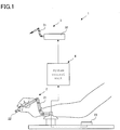
- Fig. 1 shows the manipulator system 1 described herein
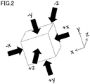
- Fig. 2 shows a triaxial acceleration sensor that is used as one example of the tapping sensor unit 22 described herein.
- the manipulator system 1 includes an operating unit 2 operated by an operator, a manipulator 3 operated by the operating unit 2, and a system control unit 4 that controls the manipulator 3 in association with the operation of the operating unit 2.
- the operating unit 2 includes a master arm 21 operated by the operator, a tapping sensor unit 22 that detects vibrations or movements, and an impact sensor unit 23 that detects impacts or the like.
- the manipulator 3 includes a main manipulator unit 31 and a driver 32.
- the master arm 21 conforms in shape to the main manipulator unit 31, and issues instructions about the operation of the main manipulator unit 31 and the driving of the driver 32.
- the system control unit 4 controls the driver 32 such that the main manipulator unit 31 moves in conformity with movement of the master arm 21.
- the tapping sensor unit 22 includes a triaxial acceleration sensor that detects movements of three axes, an imaging sensor that images how they move to detect the presence or absence of vibrations, or the like. As can be seen from Fig. 2 , the triaxial acceleration sensor that detects vibrations in the ⁇ x, ⁇ y and ⁇ z directions.
- the impact sensor unit 23 is located in a position corresponding to the operator's elbow to detect input with tapping by the operator's elbow.
- this sensor unit 23 may be a mono-axial acceleration sensor, a sensor that detects contacts, or the like.
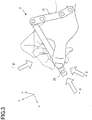
- Fig. 3 shows one example of the operation of the operating unit 2 in the manipulator system 1 described herein
- Fig. 4 shows another example of the operation of the operating unit 2 in the manipulator system 1 described herein.
- the operator grips the master arm 21 of the operating unit 2. As the operator puts the master arm 21 into movement, it allows for the main manipulator unit 31 to move in conformity with movement of the master arm 21.
- the operator taps the master arm 21 so that vibrations can be given on the tapping sensor unit 22, allowing for the main manipulator unit 31 to make settings changes, mode conversions, and so on.
- the tap sensor unit 22 detects an input from the -y direction, and when the operator taps the master arm 21 with the left hand, the index finger or the like from the front, the tap sensor unit 22 detects an input from the -x direction. Alternatively, when the operator taps the master arm 21 with the thumb or the like from the left side, the tap sensor unit 22 detects an input from the +z direction.
- the tap sensor unit 22 detects an input from the -z direction
- the tap sensor unit 22 detects an input from the +y direction. Referring here to a direction such as the +x direction in which it is difficult for the operator to tap the master arm 21, such an impact sensor unit 23 as shown in Fig. 1 may be allocated to an input in the +x direction.
- the setting changes, mode conversions or the like of the main manipulator unit 31 may be implemented depending on the intensity, number or interval of tappings, etc.
- the medical system 10 that incorporates the manipulator system 1 described herein will now be explained.
- Fig. 5 shows the medical system 10 that incorporates the manipulator system 1 described herein
- Fig. 6 is illustrative of the architecture of the manipulator 3 at the distal end of the overtube 33 described herein.
- the medical system 10 described herein preferably operates in the master-slave mode.
- the medical system 10 includes an operating unit 2 including a master arm 21, a master input unit 5 for issuance of an operating command and a slave manipulator 6 including a slave arm 61, and implements remote control of the slave arm 61 and manipulator 3 in such a way as to keep track of the operation of the master arm 21 by an operator Op.
- An operating command is sent by way of the master arm 21 to a master controller 41 in the system control unit 4 where it is subjected to optional transformation processing, after which it is entered in a slave controller 43 or a manipulator controller 42. Thereafter, an operating signal is sent from the manipulator controller 42 to the slave manipulator 6 to put the slave arm 61 and manipulator 3 into operation.
- An electric scalpel controller 44 gains control of output settings for an electric scalpel, etc.
- a display controller 45 gains control of setting changes for an endoscope 31c and a display unit 51.
- the slave manipulator 6 is placed on an operating table 11 on which a patient P lies down.
- the slave arm 61 includes a plurality of joints having a multi-degree of freedom so that it can be put into multi-axis operation.
- the respective joints having a multi-degree of freedom are individually driven by a power source (not shown) such as a servo motor having an incremental encoder or decelerator.
- the slave arm 61 is provided at its distal end with the manipulator 3 that is inserted through the body cavity of the patient P for surgical procedures.
- the manipulator 3 includes treatment tools 31a, 31b and an endoscope 31c, and is inserted through an overtube 33.
- the distal end of the overtube 33 is inserted through the body cavity of the patient P.
- a plurality of treatment tools 31a and 31b because of being selectively used depending on the surgical procedure applied, are provided with different distal-end treatment structures or configurations; they may be attached to or detached from the distal end portion of the slave arm 61 for replacements or, alternatively, they may be inserted into or pulled out of a channel formed through the overtube 33 for replacements or diverse surgical procedures.
- the endoscope 31c acquires images of an operative field including the internal site of the patient's body to be operated by the treatment tools 31a and 31b.
- the master input portion 5 includes a plurality of master arms 21 operated by an operator Op and a display unit 51 for displaying images acquired through the endoscope 31c.
- Each master arm 21 has a known construction capable of multi-axis movements, and is gripped by a surgeon to issue an operating command to a distal end side near to the operator Op.
- the insert portion described herein includes a flexible, elongated overtube 33, and treatment tools 31a, 31b and endoscope 31c inserted through an insertion bore in the overtube 33 through which the manipulator is inserted.
- the treatment tools 31a, 31b and endoscope 31c have a structure applicable to the manipulator system 1 described herein.
- the manipulator 3 described herein includes a first treatment tool 31a and a second treatment tool 31b.
- the first treatment tool 31a includes an electric scalpel and the second treatment tool 31b includes a hand grip.
- the manipulator 3 is extendable from the overtube 33, and constructed of a bending assembly in which there are plural joint rings arranged in an axial direction. Fixed to the most distal-end side are both ends of an operating wire for driving the bending assembly, and the operating wire may be driven to bend the bending assembly.
- the bending assembly may also be rotated in the axial direction.
- the overtube 33 per se may preferably be bent, and rotated in the axial direction as well.
- the slave arm 61, manipulator 3 and so on may be controlled by the master arm 21 of the operating unit 2.
- the master arm 21 described herein is provided with the tap sensor unit 22 shown in Fig. 1 such that the operator Op can tap the master arm 21 thereby making a switchover to the control mode for controlling the slave arm 61, manipulator 3, an electric scalpel that is the first treatment tool 31a or the display unit 51, or the like.
- a tap in the +y direction for instance, there is a switchover to the mode for controlling the slave arm 61, and with a tap in the -y direction, there is a switchover to the mode for controlling the manipulator 3, etc.
- information corresponding to the mode applied is displayed on the display unit 51.
- the tap sensor unit 22 may be provided on the slave arm 61 or the like or, alternatively, it may be operated by another operator Op.
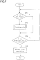
- Fig. 7 is a tap control flowchart for the medical system described herein.
- Step 1 whether or not there is the tapping mode set is determined in Step 1 (ST1).
- Step 1 When there is the tapping mode in Step 1, the control process goes to Step 2 for the subroutine of the tapping mode (ST2) that will be described later. When there is no tapping mode in Step 1, the control process goes to Step 3.
- Step 3 Whether or not the manipulator system 1 is in operation is then determined in Step 3 (ST3).
- the control process returns back to Step 1.
- the control process goes to Step 4 for master-slave operation (ST4).
- Fig. 8 is one example of the control flowchart for the tapping mode of the medical system described herein.
- Step 11 whether or not the tapping direction is in the ⁇ z direction is first determined in Step 11 (ST11).
- the control process goes to Step 12 in which there is a shift to a clutch mode for treatment tool connection/disconnection (ST12), after which the control process goes back to Step 11.
- the control process goes to Step 13 in which there is a shift to a viewing zoom mode for endoscope zooming (ST13), after which the control process returns back to Step 11.
- Step 14 When the tapping direction is not the ⁇ z direction in Step 11, whether or not the tapping direction is the ⁇ x direction is determined in Step 14 (ST14).
- the control process shifts to a treatment scaling mode for choosing a scaling function of varying the operating ratio between the master arm and the slave arm (ST15), after which the control process returns back to Step 11.
- the control process goes to a viewing special light mode for choosing illumination light in Step 16 (ST16), after which the control process returns back to Step 11.
- Step 17 In which whether or not the tapping direction is the ⁇ y direction is determined (ST17).
- the control process goes to Step 18 in which there is a shift to a cauterization/incision mode of setting an output for an energy treatment tool such an electric scalpel (ST18), after which the control process returns back to Step 11.
- the control process goes to Step 19 in which the mode is cleared (ST19), and the control process then returns back to the control flow shown in Fig. 7 .
- the tapping direction is not the ⁇ y direction in Step 17
- the control process returns back to Step 11.
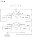
- Fig. 9 is one example of the control flowchart for the clutch mode.
- Step 21 whether or not the tapping direction is the ⁇ x direction is first determined in Step 21 (ST21).
- the control process goes to Step 22 in which the control process moves back to the previous option (ST22), after which it returns back to Step 21.
- the control process goes to Step 23 in which it moves to the next option (ST23), after which the control process returns back to Step 21.
- Fig. 10 shows one example of the clutch mode transition.
- connection/disconnection portions are sequentially selected.
- the connection/disconnection of the treatment tools and endoscope may be selected for each tapping.
- the treatment tools for the right arm and the left arm are turned on in such a way as to be controllable upon detection of a tap on the master arm 21 in the +x direction.
- the treatment tool for the left arm is selectively turned on in such a way as to be controllable.
- Step 24 determines whether or not the tapping direction is the ⁇ y direction (ST24).
- the control process goes to Step 25 to determine an option to be selected (ST25), after which it returns back to Step 11 shown in Fig. 8 .
- the control process goes to Step 26 to cancel the selected option (ST26), after which it returns back to Step 11 shown in Fig. 8 .
- control may be implemented in such a flow as shown in Fig. 9 .
- a different criterion for tapping may be relied upon.
- the criterion for tapping is defined by the tapping direction in the embodiment described herein; however, the criterion may be the number or intensity of tappings. Transitions within the modes of Fig. 10 may be set within the respective modes.
- the operating unit 2 that is put by the operator into operation
- the manipulator 3 that is operated by the operating unit 2
- the system control unit 4 that controls the manipulator 3 in association with operation of the operating unit 2 and the tapping sensor unit 22, 23 for detecting tapping by the operator, it enables the system control unit 4 to switch between controls in association with information detected by the tapping sensor unit 22 so that diverse operations or manipulations are achievable in limited space.
- the information detected by the tapping sensor unit 22 includes the direction, intensity or number of tappings and the system control unit 4 implements control set for each piece of information in association with the information detected by the tapping sensor unit 22, 23, it is possible to facilitate control by tapping by the operator, resulting in improvements in operability.
- the operating unit 2 includes the master arm 21 for coordination with the manipulator 3 and the tapping sensor unit 22 is provided on the master arm 21, it is possible to introduce much more improvements in operability.
- the system control unit 4 includes the clutch control for connection/disconnection of actuation of the manipulator 3 in association with information detected by the tapping sensor unit 22, it is possible to rapidly deactivate the manipulator 3 in case of emergency.
- the manipulator system 10 incorporating the manipulator system 1 which, as described above, includes the master input unit 5 that includes the operating unit 2 for issuance of an operating command and the slave manipulator 6 including the slave arm 61 and manipulator 3 and in which the slave arm 61 is remotely controlled in such a way as to keep track of operation of the master arm 21, it is possible to achieve more diverse operations. It is also possible for another operator Oa to carry out tapping to determine a speed for positioning of the slave arm 61, facilitating location and positioning prior to surgical operations or changes in location incidental to position changing during surgical operations.
- the manipulator 3 includes the treatment tools 31a, 31b and endoscope 31c
- the master input unit 5 includes the display unit 51 adapted to display images taken through the endoscope 31c
- the system control unit 4 makes a switchover between at least the treatment tool 31a, 31b, the endoscope 31c and the display unit 51 in association with information detected by the tapping sensor unit 22, 23, it is possible for the operator to facilitate selection by tapping.
Landscapes
- Engineering & Computer Science (AREA)
- Health & Medical Sciences (AREA)
- Life Sciences & Earth Sciences (AREA)
- Surgery (AREA)
- Robotics (AREA)
- Nuclear Medicine, Radiotherapy & Molecular Imaging (AREA)
- Veterinary Medicine (AREA)
- Biomedical Technology (AREA)
- Heart & Thoracic Surgery (AREA)
- Medical Informatics (AREA)
- Molecular Biology (AREA)
- Animal Behavior & Ethology (AREA)
- General Health & Medical Sciences (AREA)
- Public Health (AREA)
- General Engineering & Computer Science (AREA)
- Theoretical Computer Science (AREA)
- Human Computer Interaction (AREA)
- Physics & Mathematics (AREA)
- General Physics & Mathematics (AREA)
- Pathology (AREA)
- Oral & Maxillofacial Surgery (AREA)
- Mechanical Engineering (AREA)
- Manipulator (AREA)
- Surgical Instruments (AREA)
Applications Claiming Priority (2)
| Application Number | Priority Date | Filing Date | Title |
|---|---|---|---|
| JP2015034815 | 2015-02-25 | ||
| PCT/JP2016/051894 WO2016136346A1 (ja) | 2015-02-25 | 2016-01-22 | マニピュレータシステム及び医療システム |
Publications (2)
| Publication Number | Publication Date |
|---|---|
| EP3263290A1 true EP3263290A1 (de) | 2018-01-03 |
| EP3263290A4 EP3263290A4 (de) | 2018-11-21 |
Family
ID=56788336
Family Applications (1)
| Application Number | Title | Priority Date | Filing Date |
|---|---|---|---|
| EP16755096.1A Withdrawn EP3263290A4 (de) | 2015-02-25 | 2016-01-22 | Manipulatorsystem und medizinisches system |
Country Status (5)
| Country | Link |
|---|---|
| US (1) | US9974620B2 (de) |
| EP (1) | EP3263290A4 (de) |
| JP (1) | JP6084344B2 (de) |
| CN (1) | CN107073704A (de) |
| WO (1) | WO2016136346A1 (de) |
Cited By (1)
| Publication number | Priority date | Publication date | Assignee | Title |
|---|---|---|---|---|
| CN112959327A (zh) * | 2021-03-31 | 2021-06-15 | 上海电气集团股份有限公司 | 机器人运动控制方法、系统、电子设备及存储介质 |
Families Citing this family (8)
| Publication number | Priority date | Publication date | Assignee | Title |
|---|---|---|---|---|
| KR102020393B1 (ko) * | 2017-08-23 | 2019-09-11 | 한국기계연구원 | 원격 초음파 진단시스템 |
| WO2019222495A1 (en) | 2018-05-18 | 2019-11-21 | Auris Health, Inc. | Controllers for robotically-enabled teleoperated systems |
| US11135030B2 (en) | 2018-06-15 | 2021-10-05 | Verb Surgical Inc. | User interface device having finger clutch |
| CN111374767A (zh) * | 2018-12-27 | 2020-07-07 | 苏州汇控智能技术有限公司 | 医疗内窥镜智能机器人系统及内窥镜的控制方法 |
| EP4125670A4 (de) | 2020-03-27 | 2024-04-17 | Auris Health, Inc. | Handmanipulierte eingabevorrichtung für robotersystem |
| CN112259192A (zh) * | 2020-10-22 | 2021-01-22 | 华志微创医疗科技(北京)有限公司 | 一种手术操作系统以及控制方法 |
| CN112568998B (zh) * | 2020-12-08 | 2022-08-05 | 北京天使之手机器人科技有限公司 | 一种远程主从交互式医疗系统及方法 |
| CN114788735B (zh) * | 2021-01-25 | 2025-01-03 | 北京天使之手机器人科技有限公司 | 具有主端力反馈的远程交互式超声引导穿刺系统及方法 |
Family Cites Families (13)
| Publication number | Priority date | Publication date | Assignee | Title |
|---|---|---|---|---|
| JPH05261691A (ja) * | 1992-03-18 | 1993-10-12 | Fujitsu Ltd | 冗長マニピュレータ制御方式 |
| US8398541B2 (en) * | 2006-06-06 | 2013-03-19 | Intuitive Surgical Operations, Inc. | Interactive user interfaces for robotic minimally invasive surgical systems |
| US20070257881A1 (en) * | 2006-05-08 | 2007-11-08 | Marja-Leena Nurmela | Music player and method |
| JP4916011B2 (ja) | 2007-03-20 | 2012-04-11 | 株式会社日立製作所 | マスタ・スレーブ式マニピュレータシステム |
| US9211160B2 (en) * | 2008-01-16 | 2015-12-15 | Luiz Geraldo Pivotto | Remotely controlled catheter insertion system with automatic control system |
| JP5192898B2 (ja) | 2008-04-25 | 2013-05-08 | オリンパスメディカルシステムズ株式会社 | マニピュレータシステム |
| US20100134327A1 (en) * | 2008-11-28 | 2010-06-03 | Dinh Vincent Vinh | Wireless haptic glove for language and information transference |
| US9439736B2 (en) * | 2009-07-22 | 2016-09-13 | St. Jude Medical, Atrial Fibrillation Division, Inc. | System and method for controlling a remote medical device guidance system in three-dimensions using gestures |
| US8521331B2 (en) * | 2009-11-13 | 2013-08-27 | Intuitive Surgical Operations, Inc. | Patient-side surgeon interface for a minimally invasive, teleoperated surgical instrument |
| US8682489B2 (en) | 2009-11-13 | 2014-03-25 | Intuitive Sugical Operations, Inc. | Method and system for hand control of a teleoperated minimally invasive slave surgical instrument |
| US20140267024A1 (en) * | 2013-03-15 | 2014-09-18 | Eric Jeffrey Keller | Computing interface system |
| JP6297784B2 (ja) * | 2013-03-21 | 2018-03-20 | 株式会社椿本チエイン | マニピュレータ装置 |
| JP5632040B2 (ja) * | 2013-05-17 | 2014-11-26 | オリンパスイメージング株式会社 | 撮像装置およびそのモード切換え方法 |
-
2016
- 2016-01-22 JP JP2016553036A patent/JP6084344B2/ja not_active Expired - Fee Related
- 2016-01-22 EP EP16755096.1A patent/EP3263290A4/de not_active Withdrawn
- 2016-01-22 WO PCT/JP2016/051894 patent/WO2016136346A1/ja not_active Ceased
- 2016-01-22 CN CN201680003237.2A patent/CN107073704A/zh active Pending
-
2017
- 2017-05-09 US US15/590,289 patent/US9974620B2/en active Active
Cited By (2)
| Publication number | Priority date | Publication date | Assignee | Title |
|---|---|---|---|---|
| CN112959327A (zh) * | 2021-03-31 | 2021-06-15 | 上海电气集团股份有限公司 | 机器人运动控制方法、系统、电子设备及存储介质 |
| CN112959327B (zh) * | 2021-03-31 | 2022-07-29 | 上海电气集团股份有限公司 | 机器人运动控制方法、系统、电子设备及存储介质 |
Also Published As
| Publication number | Publication date |
|---|---|
| WO2016136346A1 (ja) | 2016-09-01 |
| JPWO2016136346A1 (ja) | 2017-04-27 |
| EP3263290A4 (de) | 2018-11-21 |
| JP6084344B2 (ja) | 2017-02-22 |
| CN107073704A (zh) | 2017-08-18 |
| US9974620B2 (en) | 2018-05-22 |
| US20170239008A1 (en) | 2017-08-24 |
Similar Documents
| Publication | Publication Date | Title |
|---|---|---|
| EP3263290A1 (de) | Manipulatorsystem und medizinisches system | |
| EP3025671B1 (de) | Medizinisches system | |
| EP2814642B1 (de) | Benutzerauswahl für robotersystem-betriebsarten mit benutzeraktionen zur modusunterscheidung | |
| US11517384B2 (en) | Surgical system and method for controlling the same | |
| EP2550926B1 (de) | Medizinisches manipulatorsystem | |
| JP5744455B2 (ja) | マスタ・スレーブ方式マニピュレータの制御装置及びその制御方法 | |
| EP2982330B1 (de) | Vorrichtung zum austausch eines behandlungswerkzeugs und medizinisches system | |
| CN104470449B (zh) | 医疗用操作装置 | |
| WO2011058530A1 (en) | Human-robot shared control for endoscopic assistant robot | |
| WO2015005072A1 (ja) | 手術支援ロボット | |
| US10660720B2 (en) | Surgical-manipulator operating device and surgical-manipulator system | |
| KR102199910B1 (ko) | 탈부착형 로봇 수술 도구를 이용한 다자유도 복강경 수술 장치 | |
| JP7330543B2 (ja) | 着用可能な手術用ロボットアーム | |
| KR101063281B1 (ko) | 싱글 포트 수술용 어댑터 | |
| US11399910B2 (en) | Medical system |
Legal Events
| Date | Code | Title | Description |
|---|---|---|---|
| STAA | Information on the status of an ep patent application or granted ep patent |
Free format text: STATUS: THE INTERNATIONAL PUBLICATION HAS BEEN MADE |
|
| PUAI | Public reference made under article 153(3) epc to a published international application that has entered the european phase |
Free format text: ORIGINAL CODE: 0009012 |
|
| STAA | Information on the status of an ep patent application or granted ep patent |
Free format text: STATUS: REQUEST FOR EXAMINATION WAS MADE |
|
| 17P | Request for examination filed |
Effective date: 20170912 |
|
| AK | Designated contracting states |
Kind code of ref document: A1 Designated state(s): AL AT BE BG CH CY CZ DE DK EE ES FI FR GB GR HR HU IE IS IT LI LT LU LV MC MK MT NL NO PL PT RO RS SE SI SK SM TR |
|
| AX | Request for extension of the european patent |
Extension state: BA ME |
|
| DAV | Request for validation of the european patent (deleted) | ||
| DAX | Request for extension of the european patent (deleted) | ||
| A4 | Supplementary search report drawn up and despatched |
Effective date: 20181022 |
|
| RIC1 | Information provided on ipc code assigned before grant |
Ipc: A61B 34/37 20160101ALI20181016BHEP Ipc: A61B 34/30 20160101ALI20181016BHEP Ipc: A61B 34/00 20160101ALI20181016BHEP Ipc: A61B 34/35 20160101ALI20181016BHEP Ipc: B25J 3/00 20060101AFI20181016BHEP Ipc: G06F 3/01 20060101ALI20181016BHEP |
|
| STAA | Information on the status of an ep patent application or granted ep patent |
Free format text: STATUS: THE APPLICATION IS DEEMED TO BE WITHDRAWN |
|
| 18D | Application deemed to be withdrawn |
Effective date: 20190521 |