EP3025671B1 - Medizinisches system - Google Patents
Medizinisches system Download PDFInfo
- Publication number
- EP3025671B1 EP3025671B1 EP14829426.7A EP14829426A EP3025671B1 EP 3025671 B1 EP3025671 B1 EP 3025671B1 EP 14829426 A EP14829426 A EP 14829426A EP 3025671 B1 EP3025671 B1 EP 3025671B1
- Authority
- EP
- European Patent Office
- Prior art keywords
- arm
- slave
- slave arm
- master
- joints
- Prior art date
- Legal status (The legal status is an assumption and is not a legal conclusion. Google has not performed a legal analysis and makes no representation as to the accuracy of the status listed.)
- Active
Links
- VQQXDBPNEPNNNS-UHFFFAOYSA-N C(C1)C2=C1CCC2 Chemical compound C(C1)C2=C1CCC2 VQQXDBPNEPNNNS-UHFFFAOYSA-N 0.000 description 1
Images


Classifications
-
- B—PERFORMING OPERATIONS; TRANSPORTING
- B25—HAND TOOLS; PORTABLE POWER-DRIVEN TOOLS; MANIPULATORS
- B25J—MANIPULATORS; CHAMBERS PROVIDED WITH MANIPULATION DEVICES
- B25J9/00—Program-controlled manipulators
- B25J9/16—Program controls
- B25J9/1679—Program controls characterised by the tasks executed
- B25J9/1689—Teleoperation
-
- A—HUMAN NECESSITIES
- A61—MEDICAL OR VETERINARY SCIENCE; HYGIENE
- A61B—DIAGNOSIS; SURGERY; IDENTIFICATION
- A61B34/00—Computer-aided surgery; Manipulators or robots specially adapted for use in surgery
- A61B34/30—Surgical robots
-
- A—HUMAN NECESSITIES
- A61—MEDICAL OR VETERINARY SCIENCE; HYGIENE
- A61B—DIAGNOSIS; SURGERY; IDENTIFICATION
- A61B34/00—Computer-aided surgery; Manipulators or robots specially adapted for use in surgery
- A61B34/30—Surgical robots
- A61B34/32—Surgical robots operating autonomously
-
- A—HUMAN NECESSITIES
- A61—MEDICAL OR VETERINARY SCIENCE; HYGIENE
- A61B—DIAGNOSIS; SURGERY; IDENTIFICATION
- A61B34/00—Computer-aided surgery; Manipulators or robots specially adapted for use in surgery
- A61B34/30—Surgical robots
- A61B34/37—Leader-follower robots
-
- A—HUMAN NECESSITIES
- A61—MEDICAL OR VETERINARY SCIENCE; HYGIENE
- A61B—DIAGNOSIS; SURGERY; IDENTIFICATION
- A61B34/00—Computer-aided surgery; Manipulators or robots specially adapted for use in surgery
- A61B34/70—Manipulators specially adapted for use in surgery
- A61B34/74—Manipulators with manual electric input means
-
- B—PERFORMING OPERATIONS; TRANSPORTING
- B25—HAND TOOLS; PORTABLE POWER-DRIVEN TOOLS; MANIPULATORS
- B25J—MANIPULATORS; CHAMBERS PROVIDED WITH MANIPULATION DEVICES
- B25J3/00—Manipulators of leader-follower type, i.e. both controlling unit and controlled unit perform corresponding spatial movements
- B25J3/04—Manipulators of leader-follower type, i.e. both controlling unit and controlled unit perform corresponding spatial movements involving servo mechanisms
-
- A—HUMAN NECESSITIES
- A61—MEDICAL OR VETERINARY SCIENCE; HYGIENE
- A61B—DIAGNOSIS; SURGERY; IDENTIFICATION
- A61B34/00—Computer-aided surgery; Manipulators or robots specially adapted for use in surgery
- A61B34/20—Surgical navigation systems; Devices for tracking or guiding surgical instruments, e.g. for frameless stereotaxis
- A61B2034/2046—Tracking techniques
- A61B2034/2059—Mechanical position encoders
-
- A—HUMAN NECESSITIES
- A61—MEDICAL OR VETERINARY SCIENCE; HYGIENE
- A61B—DIAGNOSIS; SURGERY; IDENTIFICATION
- A61B34/00—Computer-aided surgery; Manipulators or robots specially adapted for use in surgery
- A61B34/30—Surgical robots
- A61B2034/301—Surgical robots for introducing or steering flexible instruments inserted into the body, e.g. catheters or endoscopes
-
- A—HUMAN NECESSITIES
- A61—MEDICAL OR VETERINARY SCIENCE; HYGIENE
- A61B—DIAGNOSIS; SURGERY; IDENTIFICATION
- A61B90/00—Instruments, implements or accessories specially adapted for surgery or diagnosis and not covered by any of the groups A61B1/00 - A61B50/00, e.g. for luxation treatment or for protecting wound edges
- A61B90/06—Measuring instruments not otherwise provided for
- A61B2090/067—Measuring instruments not otherwise provided for for measuring angles
-
- Y—GENERAL TAGGING OF NEW TECHNOLOGICAL DEVELOPMENTS; GENERAL TAGGING OF CROSS-SECTIONAL TECHNOLOGIES SPANNING OVER SEVERAL SECTIONS OF THE IPC; TECHNICAL SUBJECTS COVERED BY FORMER USPC CROSS-REFERENCE ART COLLECTIONS [XRACs] AND DIGESTS
- Y10—TECHNICAL SUBJECTS COVERED BY FORMER USPC
- Y10S—TECHNICAL SUBJECTS COVERED BY FORMER USPC CROSS-REFERENCE ART COLLECTIONS [XRACs] AND DIGESTS
- Y10S901/00—Robots
- Y10S901/02—Arm motion controller
-
- Y—GENERAL TAGGING OF NEW TECHNOLOGICAL DEVELOPMENTS; GENERAL TAGGING OF CROSS-SECTIONAL TECHNOLOGIES SPANNING OVER SEVERAL SECTIONS OF THE IPC; TECHNICAL SUBJECTS COVERED BY FORMER USPC CROSS-REFERENCE ART COLLECTIONS [XRACs] AND DIGESTS
- Y10—TECHNICAL SUBJECTS COVERED BY FORMER USPC
- Y10S—TECHNICAL SUBJECTS COVERED BY FORMER USPC CROSS-REFERENCE ART COLLECTIONS [XRACs] AND DIGESTS
- Y10S901/00—Robots
- Y10S901/27—Arm part
- Y10S901/28—Joint
Definitions
- the present invention relates to medical systems.
- Another known medical system includes a single slave arm and multiple types of distal-end treatment sections that are attachable to the arm.
- an operable section can be replaced according to the type of distal-end treatment section to be used (for example, see Patent Literature 3).
- US 2012/191247 A1 discloses a master-slave manipulator, in which the slave manipulator is controlled in accordance with a joint driving command value generated by means of a dedicated second operation unit.
- WO 00/30548 A1 relates to a robotics surgical system, comprising at least four manipulator arms which may sequentially be controlled by left and right master control devices.
- US 2012/059392 A1 teaches a medical robotic system, including articulated instruments extending out of a distal end of an entry guide, wherein the movements of the instruments with respect to the entry guide are controlled in a specified manner.
- the distal end of a slave arm is provided with a distal-end treatment section, such as forceps, scissors, or a hook electrode.
- a distal-end treatment section such as forceps, scissors, or a hook electrode.
- different types of slave arms equipped with distal-end treatment sections for different purposes are often used in an interchanging manner.
- replacing of slave arms is not taken into account, and the joint configuration of the master arm and the joint configuration of the slave arm have a one-to-one correspondence relationship. Therefore, this is problematic in terms of an inability to deal with an application that requires multiple types of slave arms.
- Patent Literature 3 multiple types of distal-end treatment sections can be used in an interchanging manner.
- Patent Literature 3 is problematic in that the device is expensive since it is necessary to prepare operable sections equal in number to the number of types of distal-end treatment sections, and also in that an operable section has to be replaced every time a distal-end treatment section is replaced, thus requiring time and labor.
- the shape of a distal-end treatment section and the shape of a grip section at the master side are simply matched, and the use of slave arms having different joint configurations is not taken into account.
- the present invention has been made in view of the circumstances described above, and an object thereof is to provide a medical system and an exemplary control method, not part of the invention, therefor that allow slave arms having any joint configurations to be intuitively manipulated without requiring a dedicated master arm for each slave arm.
- the present invention provides the solution defined in independent claim 1 with further advantageous embodiments being defined in the dependent claims.
- a first aspect of the present invention provides a medical system including a first slave arm having joints; a master arm that has a joint configuration with a structure similar to a joint configuration of the first slave arm and that is operated by an operator; a second slave arm having joints; a manipulation-target switching unit that switches a manipulation target to be manipulated with the master arm between the first slave arm and the second slave arm; and a controller that controls the first slave arm and the second slave arm on the basis of an operation performed on the master arm.
- the controller switches between a first control mode and a second control mode in accordance with the joint configuration of the slave arm selected by the manipulation-target switching unit.
- the first control mode is a mode for controlling rotation of the joints of the first slave arm so that the joints of the first slave arm are rotated by rotation angles equal to rotation angles of joints of the master arm when the manipulation target is switched to the first slave arm by the manipulation-target switching unit
- the second control mode is a mode for controlling rotation of the joints of the second slave arm on the basis of a movement of a predetermined section of the master arm so as to cause a predetermined section of the second slave arm to follow the movement of the predetermined section of the master arm.
- the controller in the first control mode, makes the first slave arm reproduce a movement corresponding to that of the master arm so that the operator can intuitively manipulate the first slave arm by using the master arm.
- the controller makes the predetermined section of the second slave arm reproduce the movement of the predetermined section of the master arm so that the operator can intuitively manipulate the second slave arm having any joint configuration by using the master arm.
- a slave arm with a similar structure and a slave arm with a non-similar structure can both be dealt with using the same master arm, thereby eliminating the need for a dedicated master arm for each slave arm.
- the controller when the controller transitions from the first control mode to the second control mode, the controller may execute a reset flow, prior to the second control mode, for moving at least one of the master arm and the second slave arm so that a position and orientation of the predetermined section of the master arm and a position and orientation of the predetermined section of the second slave arm correspond with each other.
- the second control mode starts in a state where the position and orientation of the predetermined section of the second slave arm match the position and orientation of the predetermined section of the master arm, manipulation of the second slave arm can be started smoothly.
- the controller when the controller transitions from the second control mode to the first control mode, the controller may execute a reset flow, prior to the first control mode, for moving at least one of the master arm and the first slave arm so that displacement amounts of the joints of the master arm and displacement amounts of the joints of the slave arm correspond with each other.
- the first control mode starts in a state where the position and orientation of the entire first slave arm match the position and orientation of the entire master arm, manipulation of the first slave arm can be started smoothly.
- the controller may control the rotation of the joints of the second slave arm on the basis of a movement amount of a distal end of the master arm so as to cause a distal end of the second slave arm to follow a movement of the distal end of the master arm.
- the distal end of the second slave arm can be manipulated with high accuracy by using the master arm.
- the controller may calculate reverse kinematics of the second slave arm on the basis of a movement amount of the distal end of the master arm and may select a solution with which a shape of the second slave arm is most similar to the shape of the master arm from among a plurality of solutions obtained.
- the shape of the second slave arm can be roughly recognized on the basis of the master arm.
- the controller may select a solution corresponding to a minimum total of differences between displacement amounts of the joints of the master arm and displacement amounts of the joints of the second slave arm.
- the controller may select a solution that causes the second slave arm to be positioned in a space corresponding to a space in which the master arm is positioned.
- a solution that causes the shape and orientation of the second slave arm to be similar to the shape and orientation of the master arm can be selected by simple calculation.
- the controller may control rotation of any of the joints of the second slave arm having corresponding joints existing in the master arm on the basis of rotation amounts of the joints of the master arm.
- each corresponding pair of joints can be moved in a manner similar to the first control mode.
- a movement of a joint not having a corresponding joint among the joints included in the second slave arm and the master arm may be limited.
- the controller may cause the second slave arm to advance and recede so as to dispose a distal-end portion of the second slave arm at a position and orientation corresponding to a position and orientation of a distal-end portion of the master arm.
- the distal end of the second slave arm can be made to follow the movement of the distal end of the master arm with high accuracy even when the distances between the joints are different between the master arm and the second slave arm.
- the controller may control the second slave arm so that the joint located at a most distal end of the second slave arm is disposed at a position and orientation corresponding to a position and orientation of the joint located at a most distal end of the master arm.
- the distal end of the second slave arm can be made to follow the movement of the distal end of the master arm with high accuracy even when the distances between the joints are different between the master arm and the second slave arm.
- a second aspect of the present invention provides a control method for a medical system having a plurality of slave arms each having joints and a master arm operated by an operator.
- the control method includes alternately selecting a manipulation target to be manipulated with the master arm from among the plurality of slave arms; and switching between a first control mode and a second control mode in accordance with whether or not a joint configuration of the selected slave arm and a joint configuration of the master arm have structures similar to each other.
- the first control mode is a mode for controlling rotation of joints of the slave arm on the basis of rotation amounts of joints of the master arm so that the slave arm has a shape similar to a shape of the master arm.
- the second control mode is a mode for controlling the rotation of the joints of the slave arm on the basis of a movement of a predetermined section of the master arm so as to cause a predetermined section of the slave arm to follow the movement of the predetermined section of the master arm.
- a reset flow for moving at least one of the second slave arm and the master arm may be executed prior to the second control mode so that a position and orientation of the predetermined section of the second slave arm and a position and orientation of the predetermined section of the master arm correspond with each other.
- a reset flow for moving at least one of the first slave arm and the master arm may be executed prior to the first control mode so that displacement amounts of the joints of the first slave arm and displacement amounts of the joints of the master arm correspond with each other.
- the present invention is advantageous in that slave arms having any joint configurations can be intuitively manipulated without requiring a dedicated master arm for each slave arm.
- a medical system 100 according to an embodiment of the present invention will be described below with reference to the drawings.
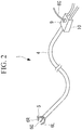
- the medical system 100 includes a slave manipulator 1 to be inserted into the body of a patient P, and an operation input unit 2 and a controller 3 that are disposed in the vicinity of a surgical table on which the patient P lies.
- the distal end of the slave manipulator 1 is provided with an endoscope 5 and slave arms 6L, 6R, and 6C, which will be described later.
- an operator Op inserts the slave manipulator 1 into the body of the patient P through his/her anus and operates the operation input unit 2 while observing an internal body image acquired by the endoscope 5 and displayed on a display 12 provided on the operation input unit 2, the controller 3 controls the slave manipulator 1 on the basis of an operation input to the operation input unit 2.
- the operator Op can remotely control the slave manipulator 1 located inside the body and perform a medical treatment inside the body by using the slave arms 6L, 6R, and 6C provided in the slave manipulator 1.
- the slave manipulator 1 includes an elongated flexible section 4 to be inserted into the body, and the endoscope 5 and the three slave arms 6L, 6R, and 6C, which are provided at the distal end of the flexible section 4.
- the slave manipulator 1 may alternatively have a rigid insertion section in place of the flexible section 4.
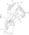
- Fig. 3 is an external view illustrating the distal end portion of the slave manipulator 1.
- the endoscope 5 can acquire a bird's-eye-view image of the three slave arms 6L, 6R, and 6C arranged in the radial direction of the flexible section 4.
- Two of the three slave arms are the left slave arm (first slave arm) 6L and the right slave arm (first slave arm) 6R, which are provided at the distal end of the flexible section 4.
- the distal ends of these slave arms 6L and 6R are respectively provided with distal-end treatment sections 8L and 8R (e.g., forceps for gripping biological tissue).
- the one remaining slave arm is an arbitrary slave arm (second slave arm) 6C disposed at the distal end of the flexible section 4 via a channel (not shown) formed in the flexible section 4.
- the channel extends from the distal end of the flexible section 4 to a port 9 provided at the base end of the flexible section 4.
- the central slave arm 6C inserted into the channel through the port 9 protrudes from a channel opening formed between the left slave arm 6L and the right slave arm 6R so as to be disposed between the right slave arm 6R and the left slave arm 6L.
- the distal end of the slave arm 6C is provided with a distal-end treatment section 8C (e.g., electric scalpel).
- the three slave arms 6L, 6R, and 6C branch off at a branch section 10 where the aforementioned port 9 is provided, and are individually connected to the controller 3, as shown in Fig. 1 .
- the left and right slave arms 6L and 6R are described as being arms provided at the distal end of the flexible section 4.
- the left and right slave arms 6L and 6R may protrude from openings of channels, such that multiple slave arms are interchangeable by being inserted into and removed from the channels.
- the operation input unit 2 includes two master arms 11L and 11R and the display 12.
- the master arms include a left master arm 11L corresponding to the left slave arm 6L and a right master arm 11R corresponding to the right slave arm 6R.
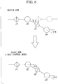
- Fig. 5 schematically illustrates joint configurations of the left and right slave arms 6L and 6R and the left and right master arms 11L and 11R.
- each master arm 11L or 11R has a joint configuration with a structure similar to that of a joint configuration of the corresponding slave arm 6L or 6R.
- each of the slave arms 6L and 6R has a roll joint J1', a yaw joint J2', a roll joint J3', and a yaw joint J4' in this order from the base end.
- each of the master arms 11L and 11R has a roll joint J1, a yaw joint J2, a roll joint J3, and a yaw joint J4 in this order from the base end.
- the roll joints J1', J3', J1, and J3 rotate about roll axes extending from the base ends to the distal ends of the respective arms 6L, 6R, 11L, and 11R in the longitudinal direction of the arms 6L, 6R, 11L, and 11R.
- the yaw joints J2', J4', J2, and J4 rotate about yaw axes extending orthogonally to the roll axes (i.e., extending orthogonally to the plane of the drawing in Fig. 5 ). Furthermore, the ratio of distances between neighboring joints is the same between the left slave arm 6L and the left master arm 11L, and the ratio of distances between neighboring joints is the same between the right slave arm 6R and the right master arm 11R.
- the controller 3 Based on the operation signals of the master arms 11L and 11R received from the operation input unit 2, the controller 3 generates drive signals for driving the joints Ji' of the slave arms 6L, 6R, and 6C and transmits the generated drive signals to the slave manipulator 1.
- the slave manipulator 1 rotates the joints Ji' in accordance with control signals so as to move the slave arms 6L, 6R, and 6C.
- the medical system 100 includes a manipulation-target switching unit 13 for changing manipulation targets to be manipulated with the master arms 11L and 11R.
- the manipulation-target switching unit 13 is a switch that is provided in the operation input unit 2 and that is to be operated by the operator Op.
- the manipulation-target switching unit 13 switches a manipulation target to be manipulated with the left master arm 11L between the left slave arm 6L and the central slave arm 6C, and switches a manipulation target to be manipulated with the right master arm 11R between the right slave arm 6R and the central slave arm 6C.
- the operator Op may preliminarily set switch targets, such that when the operator Op presses the switch, the manipulation targets are switched to the switch targets preset as default.
- the operator Op may switch between the currently-used slave arm and a slave arm to be used next, which are switch targets, by setting the switch targets using, for example, an operating panel.
- Signals indicating the slave arms selected by the manipulation-target switching unit 13 are transmitted to the controller 3.
- the controller 3 sets the manipulation targets to be manipulated with the master arms 11L and 11R to the slave arms 6L, 6R, 6C designated by the received signals.
- the operator Op uses the manipulation-target switching unit 13 to switch the manipulation target to be manipulated with one of the left and right master arms 11L and 11R to the central slave arm 6C, so that the central slave arm 6C can be manipulated by using the left master arm 11L or the right master arm 11R.
- the controller 3 selects a first control mode or a second control mode in accordance with whether or not the joint configurations of the slave arms 6L, 6R, 6C selected by the manipulation-target switching unit 13 have structures substantially similar to those of the joint configurations of the corresponding master arms 11L and 11R, and controls the slave arms 6L, 6R, 6C in accordance with the selected mode.
- a method of controlling the slave manipulator 1 with the controller 3 will be described in detail.
- the left and right slave arms 6L and 6R in their entirety are made to follow the movements of the entire left and right master arms 11L and 11R.
- the controller 3 rotates the joints Ji' of the slave arms 6L and 6R by amounts equal to the amounts of change ⁇ i in the joints Ji of the master arms 11L and 11R.
- the controller 3 controls the left slave arm 6L in accordance with the first control mode.
- the controller 3 controls the right slave arm 6R in accordance with the first control mode.
- the distal end of the central slave arm 6C is made to follow the movement of the distal end of the left or right master arm 11L or 11R.
- the controller 3 uses the amounts of change ⁇ i in the joints Ji received from the operation input unit 2 to calculate the forward kinematics of the master arm 11L or 11R, thereby calculating movement amounts dx and dy, in respective directions, of the distal end of the master arm 11L or 11R in an operational coordinate system of the master arm 11L or 11R, as shown in Fig. 7 .
- the controller 3 converts the obtained movement amounts dx and dy into movement amounts dx' and dy', in respective directions, in an operational coordinate system of the central slave arm 6C.
- the coordinate conversion in this case is desirably performed such that the moving direction of the central slave arm 6C displayed on the display 12 observed by the operator Op matches the moving direction of the master arm 11L or 11R.
- the controller 3 calculates the reverse kinematics of the slave arm 6C on the basis of the obtained movement amounts dx' and dy' so as to calculate rotation amounts ⁇ i' of the joints Ji', and rotates the joints Ji' of the slave arm 6C by the obtained rotation amounts ⁇ i'.
- the controller 3 employs the solution with which the overall shape of the slave arm 6C is most similar to the overall shape of the master arm 11L or 11R (i.e., solution 2 in the example in Fig. 7 ), such as the solution corresponding to a minimum total of differences in rotational angles between corresponding joints Ji and Ji'.
- the controller 3 stores, for each slave arm 6C, information related to the joint configuration thereof and a calculation expression, based on that information, to be used for the reverse kinematics, and selects and uses the calculation expression corresponding to the slave arm inserted in the channel.
- the slave arm inserted in the channel is recognized by a recognizing means (not shown).
- the central slave arm 6C shown has a joint configuration with a structure substantially similar to that of the joint configuration of the master arm 11L or 11R for simplifying the description.
- the joint configuration of the central slave arm 6C is arbitrary; the central slave arm 6C used may have various kinds of joint configurations, as shown in Figs. 11 to 14B , to be described later.
- the configuration that switches the manipulation targets between the left and right slave arms 6L and 6R and the central slave arm 6C has been described as an example.
- the control-mode switching operation may be performed on the basis of the joint configuration of the new slave arm.
- the left slave arm 6L when the endoscope 5 rotates by 180 degrees and the left and right positions of the slave arms 6L and 6R displayed on the display 12 are interchanged, the same method may be used if it is desired to interchange the left and right positions of the manipulation targets to be manipulated with the master arms 11L and 11R.
- the flexible section 4 of the slave manipulator 1 is inserted into the body of the patient P. While observing an internal body image acquired by the endoscope 5 with the display 12, the distal end of the slave manipulator 1 is moved to the vicinity of an affected area. Then, while observing the image displayed on the display 12, the operator Op manipulates the master arms 11L and 11R to move the slave arms 6L and 6R, thereby performing, for example, a pretreatment, which is necessary for medically treating the affected area, on the affected area and a surrounding area thereof.
- the left and right slave arms 6L and 6R are controlled in accordance with the first control mode (YES in step S1, and step S2).
- the joints Ji' of the slave arms 6L and 6R are rotated by the same amounts as the joints Ji of the master arms 11L and 11R (steps S21 and S22), so that the slave arms 6L and 6R in their entirely follow the movements of the entire master arms 11L and 11R (step S23).
- the operator Op can intuitively manipulate the left and right slave arms 6L and 6R while directly recognizing the current shapes and orientations of the slave arms 6L and 6R from the master arms 11L and 11R.
- the operator Op desires to medically treat a target site by changing to the central slave arm 6C, such as an electric scalpel, for example, the operator Op switches the manipulation target to be manipulated with the right master arm 11R to the central slave arm 6C by using the manipulation-target switching unit 13.
- the central slave arm 6C becomes capable of being moved by using the right master arm 11R.
- the controller 3 switches the first control mode to the second control mode on the basis of joint-configuration information about the switched slave arm 6C (NO in step S1) and controls the central slave arm 6C in accordance with the second control mode (step S3).
- the slave arm 6C is controlled on the basis of the movement of the distal end of the right master arm 11R (steps S31 and S32) so that the distal end of the central slave arm 6C follows the movement of the distal end of the right master arm 11R (steps S33 and S34).
- the solution that corresponds to a shape similar to that of the right master arm 11R is selected. Therefore, the operator Op can intuitively manipulate the distal end of the central slave arm 6C by using the right master arm 11R while roughly ascertaining the changing shape of the central slave arm 6C from the shape of the right master arm 11R.
- the manipulation targets to be manipulated with the left and right master arms 11L and 11R can be switched between the two slave arms 6L and 6R or between the two slave arms 6R and 6C, and the central slave arm 6C having a structure not similar to those of the master arms 11L and 11R is controlled in accordance with the second control mode in which the distal end of the central slave arm 6C is made to follow the movement of the distal end of the master arm 11L or 11R. Accordingly, slave arms having any kind of joint configuration can be intuitively manipulated by using the left and right master arms 11L and 11R. Moreover, since it is not necessary to provide a dedicated master arm for each slave arm, the device configuration is simplified, thereby reducing manufacturing costs, as well as achieving a highly-versatile design.
- the operator Op constantly needs to be aware of the bent shapes of the slave arms 6L and 6R, especially inside a narrow lumen, so as to prevent the left and right slave arms 6L and 6R from coming into contact with the surrounding tissue with a strong force.
- the working space for the central slave arm 6C is limited, and normally, the joints of the central slave arm 6C do not need to be moved by large amounts.
- the operator Op can properly move the slave arms 6L and 6R while readily ascertaining the changing shapes of the slave arms 6L and 6R. Furthermore, the left and right slave arms 6L and 6R that move in a relatively large working space are used more frequently than the central slave arm 6C that moves in a limited working space. This embodiment allows for improved ease of used since it is provided with the master arms 11L and 11R having structures substantially similar to those of the frequently-used slave arms 6L and 6R.
- the controller 3 executes a reset flow prior to the start of the second control mode.
- the controller 3 causes at least one of the central slave arm 6C and the master arms 11L and 11R to move so as to make the distal-end positions of the arms 6C and 11L or the arms 6C and 11R correspond with each other in the master space and the slave space.
- the aforementioned reset flow may be performed manually by the operator Op manipulating the master arm 11L or 11R instead of being executed automatically by the controller 3.
- the controller 3 may terminate the reset flow when a deviation between the distal-end positions of the arms 6C and 11L or the arms 6C and 11R is within a predetermined range.
- the controller 3 may cause the display 12 to display an indication for guiding the operator Op to manipulate the master arm 11L or 11R.
- the controller 3 execute a reset flow when the second control mode is to be switched to the first control mode.
- the controller 3 causes at least one of the master arm 11L or 11R, for which the manipulation target has been changed, and the slave arm 6L or 6R serving as the manipulation target to move so as to make the rotational angles of the joints Ji and Ji' of the two arms match, thereby giving the two arms similar shapes.
- This reset flow may also be performed manually by the operator Op instead of being executed automatically by the controller 3.
- the controller 3 may terminate the reset flow when a deviation between the rotational angles of the joints Ji and Ji' of the two arms 6L and 11L or the two arms 6R and 11R is within a predetermined range.
- the controller 3 may cause the display 12 to display an indication for guiding the operator Op to manipulate the master arm 11L or 11R.
- the controller 3 may have at least two of the aforementioned second control mode and first to third modifications of the second control mode to be described below and may select an appropriate second control mode in accordance with the joint configuration of the central slave arm 6C.
- the controller 3 rotates the joints Ji' by amounts equal to the amounts of change ⁇ i in the corresponding joints Ji without taking into account the movement of the joint J4, which is included in the joints Ji of the master arm 11L or 11R and is an extra joint relative to the joints Ji' of the central slave arm 6C.
- the operator Op can manipulate the master arm 11L or 11R while regarding the extra joint J4 of the master arm 11L or 11R as the distal end of the central slave arm 6C.
- the extra joint J4 may be secured with, for example, an actuator, a brake, or a clutch (not shown) so as to prevent an undesired movement thereof.
- the controller 3 rotates the joints Ji' of the central slave arm 6C that correspond to the joints Ji of the master arm 11L or 11R by amounts equal to the amounts of change ⁇ i in the joints Ji but does not control the joint J5', which is an extra joint relative to the joints Ji.
- the extra joint J5' may be secured with, for example, an actuator, a brake, or a clutch (not shown) so as to prevent an undesired movement thereof.
- At least one of the extra joint J5' and the joint J4' having a redundant relationship therewith may be selectively driven.
- the joint J4' and the joint J5' may both be driven such that the total driving amount is equal to the amount of change ⁇ 4 in the joint J4.
- the third modification of the second control mode is to be used when the central slave arm 6C has a joint arrangement in common with that of each of the left and right master arms 11L and 11R and when the ratio of distances between neighboring joints of the central slave arm 6C is different from that of the master arm 11L or 11R.
- the controller 3 moves the central slave arm 6C in a manner similar to Fig. 6 .
- the distal-end position of the central slave arm 6C becomes deviated from the distal-end position of the master arm 11L or 11R.
- the controller 3 causes the entire central slave arm 6C to advance or recede relative to the flexible section 4 so as to position the distal end of the central slave arm 6C on the same line as the distal-end portion of the master arm 11L or 11R.
- the controller 3 may drive the central slave arm 6C so that the position and orientation of the joint J4' located at the most distal end correspond to those of the corresponding joint J4.
- the solution that causes the central slave arm 6C to be positioned in the same space as the master arm 11L or 11R from among first to fourth spaces may be used, as shown in Fig. 15 .
- the first to fourth spaces are four spaces that are obtained by defining a central axis A of the base portion of each of the arms 6C, 11L, and 11R and that are divided by two orthogonal planes passing through the axis A.
- slave manipulator 1 having the three slave arms 6L, 6R, and 6C attached to the distal end of the flexible section 4
- a specific configuration of the slave manipulator 1 is not limited to this.
- two slave arms may be attached to the distal end of the flexible section 4.
- one of the slave arms may be controlled in accordance with the first control mode, and the other slave arm may be controlled in accordance with the second control mode.
- a single replaceable slave arm may be attached to the distal end of the flexible section 4.
- the switching operation between the first control mode and the second control mode may be performed on the basis of the joint configuration of that slave arm.
Landscapes
- Engineering & Computer Science (AREA)
- Health & Medical Sciences (AREA)
- Life Sciences & Earth Sciences (AREA)
- Surgery (AREA)
- Robotics (AREA)
- Medical Informatics (AREA)
- Biomedical Technology (AREA)
- Heart & Thoracic Surgery (AREA)
- Nuclear Medicine, Radiotherapy & Molecular Imaging (AREA)
- Molecular Biology (AREA)
- Animal Behavior & Ethology (AREA)
- General Health & Medical Sciences (AREA)
- Public Health (AREA)
- Veterinary Medicine (AREA)
- Mechanical Engineering (AREA)
- Manipulator (AREA)
Claims (10)
- Medizinisches System (100), umfassend:einen ersten Slave-Arm (6L, 6R), der Gelenke (Ji) aufweist;einen Master-Arm (11L, 11R), der eine Gelenkkonfiguration mit einer Struktur und Form ähnlich wie eine Gelenkkonfiguration des ersten Slave-Arms (6L, 6R) aufweist und der durch einen Bediener bedient wird;einen zweiten Slave-Arm (6C), der Gelenke (Ji) aufweist;eine Einheit (13) zum Umschalten eines Manipulationsziels, die ein Manipulationsziel, das mit dem Master-Arm (11L, 11R) zu manipulieren ist, zwischen dem ersten Slave-Arm (6L, 6R) und dem zweiten Slave-Arm (6C) umschaltet; und
ein Steuergerät (3), das den ersten Slave-Arm (6L, 6R) und den zweiten Slave-Arm (6C) auf der Grundlage einer Bedienung, die an dem Master-Arm (11L, 11R) ausgeführt wird, steuert,wobei das Steuergerät (3) zwischen einem ersten Steuermodus und einem zweiten Steuermodus in Übereinstimmung mit der Gelenkkonfiguration des Slave-Arms (6L, 6R, 6C), der durch die Einheit (13) zum Umschalten eines Manipulationsziels ausgewählt wird, umschaltet,dadurch gekennzeichnet, dass der erste Steuermodus ein Modus zum Steuern der Drehung der Gelenke (Ji) des ersten Slave-Arms (6L, 6R) ist, so dass die Gelenks (Ji) des ersten Slave-Arms (6L, 6R) um Drehwinkel gedreht werden, die gleich den Drehwinkeln der Gelenke (Ji) des Master-Arms (11L, 11R) sind, wenn das Manipulationsziel auf den ersten Slave-Arm (6L, 6R) durch die Einheit (13) zum Umschalten eines Manipulationsziels umgeschaltet wird, wobei der zweite Steuermodus ein Modus zum Steuern der Drehung der Gelenke (Ji) des zweiten Slave-Arms (6C) auf der Grundlage einer Bewegung eines vorbestimmten Teilabschnitts des Master-Arms (11L, 11R) ist, um zu bewirken, dass ein vorbestimmter Teilabschnitt des zweiten Slave-Arms (6C) der Bewegung des vorbestimmten Teilabschnitt des Master-Arms (11L, 11R) folgt. - Medizinisches System (100) nach Anspruch 1,
wobei, wenn das Steuergerät (3) von dem ersten Steuermodus auf den zweiten Steuermodus übergeht, das Steuergerät (3) einen Rückstellablauf vor dem zweiten Steuermodus durchführt, um den zweiten Slave-Arm (6C) und/oder den Master-Arm (11R, 11L) zu bewegen, so dass eine Position und Orientierung des vorbestimmten Teilabschnitts des zweiten Slave-Arms (6C) und eine Position und Orientierung des vorbestimmten Teilabschnitts des Master-Arms (11R, 11L) einander entsprechen. - Medizinisches System (100) nach Anspruch 1 oder 2,
wobei, wenn das Steuergerät (3) von dem zweiten Steuermodus auf den ersten Steuermodus übergeht, das Steuergerät (3) einen Rückstellablauf vor dem ersten Steuermodus durchführt, um den ersten Slave-Arm (6L, 6R) und/oder den Master-Arm (11R, 11L) zu bewegen, so dass die Verlagerungsbeträge der Gelenke (Ji) des ersten Slave-Arms (6L, 6R) und die Verlagerungsbeträge der Gelenke (Ji) des Master-Arms (11R, 11L) einander entsprechen. - Medizinisches System (100) nach einem der Ansprüche 1 bis 3,
wobei das Steuergerät (3) im zweiten Steuermodus die Drehung der Gelenke (Ji) des zweiten Slave-Arms (6C) auf der Grundlage eines Bewegungsbetrags eines distalen Endes des Master-Arms (11R, 11L) steuert, um zu bewirken, dass ein distales Ende des zweiten Slave-Arms (6C) einer Bewegung des distalen Endes des Master-Arms (11R, 11L) folgt. - Medizinisches System (100) nach Anspruch 4,
wobei das Steuergerät (3) im zweiten Steuermodus eine inverse Kinematik des zweiten Slave-Arms (6C) auf der Grundlage eines Bewegungsbetrags des distalen Endes des Master-Arms (11L, 11R) berechnet und eine Lösung, mit der eine Form des zweiten Slave-Arms (6C) der Form des Master-Arms (11L, 11R) möglichst ähnlich ist, aus einer Mehrzahl von erzielten Lösungen auswählt. - Medizinisches System (100) nach Anspruch 5,
wobei das Steuergerät (3) im zweiten Steuermodus eine Lösung, die einer Mindestgesamtsumme der Differenzen zwischen den Verlagerungsbeträgen der Gelenke (Ji) des Master-Arms (11L, 11R) und den Verlagerungsbeträgen der Gelenke (Ji) des zweiten Slave-Arms (6C) entspricht, auswählt. - Medizinisches System (100) nach Anspruch 5,
wobei unter der Voraussetzung, dass vier Räume gebildet werden, indem sie durch zwei Ebenen unterteilt werden, die durch eine mittlere Achse (A) eines Basisabschnitts jedes von dem zweiten Slave-Arm (6C) und dem Master-Arm (11R, 11L) gehen und die auf der mittleren Achse (A) zueinander orthogonal sind, das Steuergerät (3) eine Lösung auswählt, die bewirkt, dass der zweite Slave-Arm (6C) in einem Raum positioniert wird, der einem Raum entspricht, in dem der Master-Arm (11L, 11R) positioniert ist. - Medizinisches System (100) nach einem der Ansprüche 1 bis 3,
wobei das Steuergerät (3) im zweiten Steuermodus die Drehung eines der Gelenke (Ji) des zweiten Slave-Arms (6C), der entsprechende Gelenke (Ji) aufweist, die in dem Master-Arm (11L, 11R) existieren, auf der Grundlage von Drehbeträgen der Gelenke (Ji) des Master-Arms (111, 11R) steuert. - Medizinisches System (100) nach Anspruch 8,
wobei das Steuergerät (3) eine Bewegung eines Gelenks (Ji) begrenzt, das kein entsprechendes Gelenk (Ji) unter den Gelenken (Ji), die in dem zweiten Slave-Arm (6C) und dem Master-Arm (11L, 11R) enthalten sind, aufweist. - Medizinisches System (100) nach einem der Ansprüche 1 bis 3,
wobei das Steuergerät (3) im zweiten Steuermodus den zweiten Slave-Arm (6C) derart steuert, dass das Gelenk (Ji), das sich an einem distalsten Ende des zweiten Slave-Arms (6C) befindet, in einer Position und Orientierung angeordnet ist, die einer Position und Orientierung des Gelenks (Ji) entsprechen, das sich an einem distalsten Ende des Master-Arms (11L, 11R) befindet.
Applications Claiming Priority (2)
| Application Number | Priority Date | Filing Date | Title |
|---|---|---|---|
| JP2013155884A JP6109001B2 (ja) | 2013-07-26 | 2013-07-26 | 医療用システムおよびその作動方法 |
| PCT/JP2014/068853 WO2015012162A1 (ja) | 2013-07-26 | 2014-07-16 | 医療用システムおよびその制御方法 |
Publications (3)
| Publication Number | Publication Date |
|---|---|
| EP3025671A1 EP3025671A1 (de) | 2016-06-01 |
| EP3025671A4 EP3025671A4 (de) | 2017-04-05 |
| EP3025671B1 true EP3025671B1 (de) | 2019-02-20 |
Family
ID=52393206
Family Applications (1)
| Application Number | Title | Priority Date | Filing Date |
|---|---|---|---|
| EP14829426.7A Active EP3025671B1 (de) | 2013-07-26 | 2014-07-16 | Medizinisches system |
Country Status (5)
| Country | Link |
|---|---|
| US (1) | US10022871B2 (de) |
| EP (1) | EP3025671B1 (de) |
| JP (1) | JP6109001B2 (de) |
| CN (1) | CN105431104B (de) |
| WO (1) | WO2015012162A1 (de) |
Families Citing this family (19)
| Publication number | Priority date | Publication date | Assignee | Title |
|---|---|---|---|---|
| EP2675367B1 (de) | 2011-02-15 | 2018-03-07 | Intuitive Surgical Operations, Inc. | Systeme zur kennzeichnung einer klemmenvorhersage |
| CN106714655B (zh) | 2014-09-04 | 2020-12-29 | 迈米克创新手术有限公司 | 包括机械臂的装置和系统 |
| JP6644816B2 (ja) * | 2015-06-30 | 2020-02-12 | キヤノン ユーエスエイ, インコーポレイテッドCanon U.S.A., Inc | マニピュレータを制御する方法および装置 |
| WO2017033355A1 (ja) * | 2015-08-25 | 2017-03-02 | 川崎重工業株式会社 | マニピュレータシステム |
| WO2017037723A1 (en) | 2015-09-04 | 2017-03-09 | Memic Innovative Surgery Ltd. | Actuation of a device comprising mechanical arms |
| CN106914879A (zh) * | 2015-12-25 | 2017-07-04 | 财团法人金属工业研究发展中心 | 机械手臂动作导引系统及其操作方法 |
| CN105796179B (zh) * | 2016-03-03 | 2018-05-18 | 北京理工大学 | 一种主从介入手术机器人从端操作装置及其控制方法 |
| CA2960354A1 (en) | 2016-03-09 | 2017-09-09 | Memic Innovative Surgery Ltd. | Modular device comprising mechanical arms |
| WO2017221323A1 (ja) * | 2016-06-21 | 2017-12-28 | オリンパス株式会社 | 医療システム |
| US10973592B2 (en) | 2017-03-09 | 2021-04-13 | Memie Innovative Surgery Ltd. | Control console for surgical device with mechanical arms |
| US11779410B2 (en) | 2017-03-09 | 2023-10-10 | Momentis Surgical Ltd | Control console including an input arm for control of a surgical mechanical arm |
| GB2571319B (en) * | 2018-02-23 | 2022-11-23 | Cmr Surgical Ltd | Concurrent control of an end effector in a master-slave robotic system using multiple input devices |
| WO2019222495A1 (en) | 2018-05-18 | 2019-11-21 | Auris Health, Inc. | Controllers for robotically-enabled teleoperated systems |
| KR102221089B1 (ko) * | 2018-12-05 | 2021-02-26 | (주)미래컴퍼니 | 수술용 슬레이브 암을 원격으로 제어하는 방법 및 시스템 |
| JP2020049300A (ja) * | 2019-12-25 | 2020-04-02 | 株式会社メディカロイド | 遠隔操作装置及び遠隔手術システム |
| WO2021145051A1 (ja) | 2020-01-16 | 2021-07-22 | オリンパス株式会社 | 内視鏡システム |
| CN117222377A (zh) * | 2021-04-27 | 2023-12-12 | 川崎重工业株式会社 | 机器人系统 |
| CN117695016A (zh) * | 2022-08-24 | 2024-03-15 | 上海微创医疗机器人(集团)股份有限公司 | 机械臂的匹配方法、医生控制台和计算机可读存储介质 |
| CN116211475B (zh) * | 2023-03-21 | 2026-01-13 | 四川大学 | 一种多自由度皮肤缝合器 |
Family Cites Families (24)
| Publication number | Priority date | Publication date | Assignee | Title |
|---|---|---|---|---|
| JPH0829509B2 (ja) * | 1986-12-12 | 1996-03-27 | 株式会社日立製作所 | マニピユレ−タの制御装置 |
| CA2000818C (en) * | 1988-10-19 | 1994-02-01 | Akira Tsuchihashi | Master slave manipulator system |
| DE69332914T2 (de) | 1992-01-21 | 2004-02-26 | Sri International, Menlo Park | Chirurgisches System |
| US5876325A (en) * | 1993-11-02 | 1999-03-02 | Olympus Optical Co., Ltd. | Surgical manipulation system |
| US6364888B1 (en) * | 1996-09-09 | 2002-04-02 | Intuitive Surgical, Inc. | Alignment of master and slave in a minimally invasive surgical apparatus |
| US6459926B1 (en) * | 1998-11-20 | 2002-10-01 | Intuitive Surgical, Inc. | Repositioning and reorientation of master/slave relationship in minimally invasive telesurgery |
| US6659939B2 (en) * | 1998-11-20 | 2003-12-09 | Intuitive Surgical, Inc. | Cooperative minimally invasive telesurgical system |
| US6424885B1 (en) | 1999-04-07 | 2002-07-23 | Intuitive Surgical, Inc. | Camera referenced control in a minimally invasive surgical apparatus |
| JP2001087281A (ja) | 1999-09-20 | 2001-04-03 | Olympus Optical Co Ltd | 多機能マニピュレータ |
| US7379790B2 (en) * | 2004-05-04 | 2008-05-27 | Intuitive Surgical, Inc. | Tool memory-based software upgrades for robotic surgery |
| JP2005131417A (ja) * | 2004-12-03 | 2005-05-26 | Toshiba Corp | 医療用マニピュレータの制御方法 |
| US10555775B2 (en) * | 2005-05-16 | 2020-02-11 | Intuitive Surgical Operations, Inc. | Methods and system for performing 3-D tool tracking by fusion of sensor and/or camera derived data during minimally invasive robotic surgery |
| KR101477738B1 (ko) | 2006-06-13 | 2014-12-31 | 인튜어티브 서지컬 인코포레이티드 | 미소절개 수술 시스템 |
| US8738181B2 (en) | 2007-04-16 | 2014-05-27 | Alexander Greer | Methods, devices, and systems for automated movements involving medical robots |
| US9138129B2 (en) * | 2007-06-13 | 2015-09-22 | Intuitive Surgical Operations, Inc. | Method and system for moving a plurality of articulated instruments in tandem back towards an entry guide |
| JP5258284B2 (ja) * | 2007-12-28 | 2013-08-07 | テルモ株式会社 | 医療用マニピュレータ及び医療用ロボットシステム |
| JP4608601B2 (ja) | 2008-11-14 | 2011-01-12 | オリンパスメディカルシステムズ株式会社 | 医療用システム |
| JP5612971B2 (ja) * | 2010-09-07 | 2014-10-22 | オリンパス株式会社 | マスタスレーブマニピュレータ |
| JP5744455B2 (ja) * | 2010-09-29 | 2015-07-08 | オリンパス株式会社 | マスタ・スレーブ方式マニピュレータの制御装置及びその制御方法 |
| JP5669590B2 (ja) * | 2011-01-20 | 2015-02-12 | オリンパス株式会社 | マスタスレーブマニピュレータ及び医療用マスタスレーブマニピュレータ |
| JP6021353B2 (ja) * | 2011-08-04 | 2016-11-09 | オリンパス株式会社 | 手術支援装置 |
| JP5893330B2 (ja) * | 2011-10-18 | 2016-03-23 | オリンパス株式会社 | 操作入力装置および操作入力装置の初期化方法 |
| CN104334110B (zh) * | 2012-06-01 | 2017-10-03 | 直观外科手术操作公司 | 使用零空间回避操纵器臂与患者碰撞 |
| JP6262216B2 (ja) * | 2012-06-01 | 2018-01-17 | インテュイティブ サージカル オペレーションズ, インコーポレイテッド | 零空間を使用して操作アーム間の衝突を回避するためのシステム及び方法 |
-
2013
- 2013-07-26 JP JP2013155884A patent/JP6109001B2/ja not_active Expired - Fee Related
-
2014
- 2014-07-16 CN CN201480041731.9A patent/CN105431104B/zh active Active
- 2014-07-16 EP EP14829426.7A patent/EP3025671B1/de active Active
- 2014-07-16 WO PCT/JP2014/068853 patent/WO2015012162A1/ja not_active Ceased
-
2016
- 2016-01-19 US US15/000,341 patent/US10022871B2/en active Active
Non-Patent Citations (1)
| Title |
|---|
| None * |
Also Published As
| Publication number | Publication date |
|---|---|
| JP2015024035A (ja) | 2015-02-05 |
| JP6109001B2 (ja) | 2017-04-05 |
| CN105431104B (zh) | 2018-01-23 |
| US10022871B2 (en) | 2018-07-17 |
| CN105431104A (zh) | 2016-03-23 |
| WO2015012162A1 (ja) | 2015-01-29 |
| EP3025671A1 (de) | 2016-06-01 |
| US20160128790A1 (en) | 2016-05-12 |
| EP3025671A4 (de) | 2017-04-05 |
Similar Documents
| Publication | Publication Date | Title |
|---|---|---|
| EP3025671B1 (de) | Medizinisches system | |
| US11576735B2 (en) | Controllable steerable instrument | |
| US9974620B2 (en) | Manipulator system, and medical system | |
| EP2814642B1 (de) | Benutzerauswahl für robotersystem-betriebsarten mit benutzeraktionen zur modusunterscheidung | |
| EP2982330B1 (de) | Vorrichtung zum austausch eines behandlungswerkzeugs und medizinisches system | |
| JP6010225B2 (ja) | 医療用マニピュレータ | |
| JP6117922B2 (ja) | 医療用マニピュレータおよびその作動方法 | |
| EP3254640A1 (de) | Manipulator | |
| JP7085400B2 (ja) | 外科手術システム | |
| US20230000579A1 (en) | Orientation of user- input devices for controlling surgical arms | |
| EP2881048A1 (de) | Medizinischer manipulator | |
| WO2015005072A1 (ja) | 手術支援ロボット | |
| EP3871629B1 (de) | Am körper tragbarer chirurgischer roboterarm | |
| US20220175479A1 (en) | Surgical operation system and method of controlling surgical operation system | |
| WO2014199415A1 (ja) | 医療用マニピュレータおよびその制御方法 |
Legal Events
| Date | Code | Title | Description |
|---|---|---|---|
| PUAI | Public reference made under article 153(3) epc to a published international application that has entered the european phase |
Free format text: ORIGINAL CODE: 0009012 |
|
| 17P | Request for examination filed |
Effective date: 20160211 |
|
| AK | Designated contracting states |
Kind code of ref document: A1 Designated state(s): AL AT BE BG CH CY CZ DE DK EE ES FI FR GB GR HR HU IE IS IT LI LT LU LV MC MK MT NL NO PL PT RO RS SE SI SK SM TR |
|
| AX | Request for extension of the european patent |
Extension state: BA ME |
|
| RAP1 | Party data changed (applicant data changed or rights of an application transferred) |
Owner name: OLYMPUS CORPORATION |
|
| RIN1 | Information on inventor provided before grant (corrected) |
Inventor name: OGAWA, RYOHEI Inventor name: KISHI, KOSUKE |
|
| DAX | Request for extension of the european patent (deleted) | ||
| A4 | Supplementary search report drawn up and despatched |
Effective date: 20170302 |
|
| RIC1 | Information provided on ipc code assigned before grant |
Ipc: B25J 3/00 20060101ALI20170224BHEP Ipc: A61B 90/00 20160101AFI20170224BHEP Ipc: A61B 34/00 20160101ALI20170224BHEP |
|
| RAP1 | Party data changed (applicant data changed or rights of an application transferred) |
Owner name: OLYMPUS CORPORATION |
|
| RIN1 | Information on inventor provided before grant (corrected) |
Inventor name: KISHI, KOSUKE Inventor name: OGAWA, RYOHEI |
|
| GRAP | Despatch of communication of intention to grant a patent |
Free format text: ORIGINAL CODE: EPIDOSNIGR1 |
|
| STAA | Information on the status of an ep patent application or granted ep patent |
Free format text: STATUS: GRANT OF PATENT IS INTENDED |
|
| INTG | Intention to grant announced |
Effective date: 20180830 |
|
| GRAS | Grant fee paid |
Free format text: ORIGINAL CODE: EPIDOSNIGR3 |
|
| GRAA | (expected) grant |
Free format text: ORIGINAL CODE: 0009210 |
|
| STAA | Information on the status of an ep patent application or granted ep patent |
Free format text: STATUS: THE PATENT HAS BEEN GRANTED |
|
| AK | Designated contracting states |
Kind code of ref document: B1 Designated state(s): AL AT BE BG CH CY CZ DE DK EE ES FI FR GB GR HR HU IE IS IT LI LT LU LV MC MK MT NL NO PL PT RO RS SE SI SK SM TR |
|
| REG | Reference to a national code |
Ref country code: GB Ref legal event code: FG4D |
|
| REG | Reference to a national code |
Ref country code: CH Ref legal event code: EP |
|
| REG | Reference to a national code |
Ref country code: DE Ref legal event code: R096 Ref document number: 602014041459 Country of ref document: DE |
|
| REG | Reference to a national code |
Ref country code: AT Ref legal event code: REF Ref document number: 1097168 Country of ref document: AT Kind code of ref document: T Effective date: 20190315 |
|
| REG | Reference to a national code |
Ref country code: IE Ref legal event code: FG4D |
|
| REG | Reference to a national code |
Ref country code: NL Ref legal event code: MP Effective date: 20190220 |
|
| REG | Reference to a national code |
Ref country code: LT Ref legal event code: MG4D |
|
| PG25 | Lapsed in a contracting state [announced via postgrant information from national office to epo] |
Ref country code: FI Free format text: LAPSE BECAUSE OF FAILURE TO SUBMIT A TRANSLATION OF THE DESCRIPTION OR TO PAY THE FEE WITHIN THE PRESCRIBED TIME-LIMIT Effective date: 20190220 Ref country code: SE Free format text: LAPSE BECAUSE OF FAILURE TO SUBMIT A TRANSLATION OF THE DESCRIPTION OR TO PAY THE FEE WITHIN THE PRESCRIBED TIME-LIMIT Effective date: 20190220 Ref country code: PT Free format text: LAPSE BECAUSE OF FAILURE TO SUBMIT A TRANSLATION OF THE DESCRIPTION OR TO PAY THE FEE WITHIN THE PRESCRIBED TIME-LIMIT Effective date: 20190620 Ref country code: NO Free format text: LAPSE BECAUSE OF FAILURE TO SUBMIT A TRANSLATION OF THE DESCRIPTION OR TO PAY THE FEE WITHIN THE PRESCRIBED TIME-LIMIT Effective date: 20190520 Ref country code: NL Free format text: LAPSE BECAUSE OF FAILURE TO SUBMIT A TRANSLATION OF THE DESCRIPTION OR TO PAY THE FEE WITHIN THE PRESCRIBED TIME-LIMIT Effective date: 20190220 Ref country code: LT Free format text: LAPSE BECAUSE OF FAILURE TO SUBMIT A TRANSLATION OF THE DESCRIPTION OR TO PAY THE FEE WITHIN THE PRESCRIBED TIME-LIMIT Effective date: 20190220 |
|
| PG25 | Lapsed in a contracting state [announced via postgrant information from national office to epo] |
Ref country code: RS Free format text: LAPSE BECAUSE OF FAILURE TO SUBMIT A TRANSLATION OF THE DESCRIPTION OR TO PAY THE FEE WITHIN THE PRESCRIBED TIME-LIMIT Effective date: 20190220 Ref country code: HR Free format text: LAPSE BECAUSE OF FAILURE TO SUBMIT A TRANSLATION OF THE DESCRIPTION OR TO PAY THE FEE WITHIN THE PRESCRIBED TIME-LIMIT Effective date: 20190220 Ref country code: BG Free format text: LAPSE BECAUSE OF FAILURE TO SUBMIT A TRANSLATION OF THE DESCRIPTION OR TO PAY THE FEE WITHIN THE PRESCRIBED TIME-LIMIT Effective date: 20190520 Ref country code: GR Free format text: LAPSE BECAUSE OF FAILURE TO SUBMIT A TRANSLATION OF THE DESCRIPTION OR TO PAY THE FEE WITHIN THE PRESCRIBED TIME-LIMIT Effective date: 20190521 Ref country code: LV Free format text: LAPSE BECAUSE OF FAILURE TO SUBMIT A TRANSLATION OF THE DESCRIPTION OR TO PAY THE FEE WITHIN THE PRESCRIBED TIME-LIMIT Effective date: 20190220 Ref country code: IS Free format text: LAPSE BECAUSE OF FAILURE TO SUBMIT A TRANSLATION OF THE DESCRIPTION OR TO PAY THE FEE WITHIN THE PRESCRIBED TIME-LIMIT Effective date: 20190620 |
|
| REG | Reference to a national code |
Ref country code: AT Ref legal event code: MK05 Ref document number: 1097168 Country of ref document: AT Kind code of ref document: T Effective date: 20190220 |
|
| PG25 | Lapsed in a contracting state [announced via postgrant information from national office to epo] |
Ref country code: EE Free format text: LAPSE BECAUSE OF FAILURE TO SUBMIT A TRANSLATION OF THE DESCRIPTION OR TO PAY THE FEE WITHIN THE PRESCRIBED TIME-LIMIT Effective date: 20190220 Ref country code: SK Free format text: LAPSE BECAUSE OF FAILURE TO SUBMIT A TRANSLATION OF THE DESCRIPTION OR TO PAY THE FEE WITHIN THE PRESCRIBED TIME-LIMIT Effective date: 20190220 Ref country code: IT Free format text: LAPSE BECAUSE OF FAILURE TO SUBMIT A TRANSLATION OF THE DESCRIPTION OR TO PAY THE FEE WITHIN THE PRESCRIBED TIME-LIMIT Effective date: 20190220 Ref country code: DK Free format text: LAPSE BECAUSE OF FAILURE TO SUBMIT A TRANSLATION OF THE DESCRIPTION OR TO PAY THE FEE WITHIN THE PRESCRIBED TIME-LIMIT Effective date: 20190220 Ref country code: CZ Free format text: LAPSE BECAUSE OF FAILURE TO SUBMIT A TRANSLATION OF THE DESCRIPTION OR TO PAY THE FEE WITHIN THE PRESCRIBED TIME-LIMIT Effective date: 20190220 Ref country code: AL Free format text: LAPSE BECAUSE OF FAILURE TO SUBMIT A TRANSLATION OF THE DESCRIPTION OR TO PAY THE FEE WITHIN THE PRESCRIBED TIME-LIMIT Effective date: 20190220 Ref country code: RO Free format text: LAPSE BECAUSE OF FAILURE TO SUBMIT A TRANSLATION OF THE DESCRIPTION OR TO PAY THE FEE WITHIN THE PRESCRIBED TIME-LIMIT Effective date: 20190220 Ref country code: ES Free format text: LAPSE BECAUSE OF FAILURE TO SUBMIT A TRANSLATION OF THE DESCRIPTION OR TO PAY THE FEE WITHIN THE PRESCRIBED TIME-LIMIT Effective date: 20190220 |
|
| REG | Reference to a national code |
Ref country code: DE Ref legal event code: R097 Ref document number: 602014041459 Country of ref document: DE |
|
| PG25 | Lapsed in a contracting state [announced via postgrant information from national office to epo] |
Ref country code: SM Free format text: LAPSE BECAUSE OF FAILURE TO SUBMIT A TRANSLATION OF THE DESCRIPTION OR TO PAY THE FEE WITHIN THE PRESCRIBED TIME-LIMIT Effective date: 20190220 Ref country code: PL Free format text: LAPSE BECAUSE OF FAILURE TO SUBMIT A TRANSLATION OF THE DESCRIPTION OR TO PAY THE FEE WITHIN THE PRESCRIBED TIME-LIMIT Effective date: 20190220 |
|
| PLBE | No opposition filed within time limit |
Free format text: ORIGINAL CODE: 0009261 |
|
| STAA | Information on the status of an ep patent application or granted ep patent |
Free format text: STATUS: NO OPPOSITION FILED WITHIN TIME LIMIT |
|
| PG25 | Lapsed in a contracting state [announced via postgrant information from national office to epo] |
Ref country code: AT Free format text: LAPSE BECAUSE OF FAILURE TO SUBMIT A TRANSLATION OF THE DESCRIPTION OR TO PAY THE FEE WITHIN THE PRESCRIBED TIME-LIMIT Effective date: 20190220 |
|
| 26N | No opposition filed |
Effective date: 20191121 |
|
| PG25 | Lapsed in a contracting state [announced via postgrant information from national office to epo] |
Ref country code: MC Free format text: LAPSE BECAUSE OF FAILURE TO SUBMIT A TRANSLATION OF THE DESCRIPTION OR TO PAY THE FEE WITHIN THE PRESCRIBED TIME-LIMIT Effective date: 20190220 Ref country code: SI Free format text: LAPSE BECAUSE OF FAILURE TO SUBMIT A TRANSLATION OF THE DESCRIPTION OR TO PAY THE FEE WITHIN THE PRESCRIBED TIME-LIMIT Effective date: 20190220 |
|
| REG | Reference to a national code |
Ref country code: CH Ref legal event code: PL |
|
| GBPC | Gb: european patent ceased through non-payment of renewal fee |
Effective date: 20190716 |
|
| PG25 | Lapsed in a contracting state [announced via postgrant information from national office to epo] |
Ref country code: TR Free format text: LAPSE BECAUSE OF FAILURE TO SUBMIT A TRANSLATION OF THE DESCRIPTION OR TO PAY THE FEE WITHIN THE PRESCRIBED TIME-LIMIT Effective date: 20190220 |
|
| REG | Reference to a national code |
Ref country code: BE Ref legal event code: MM Effective date: 20190731 |
|
| PG25 | Lapsed in a contracting state [announced via postgrant information from national office to epo] |
Ref country code: GB Free format text: LAPSE BECAUSE OF NON-PAYMENT OF DUE FEES Effective date: 20190716 |
|
| PG25 | Lapsed in a contracting state [announced via postgrant information from national office to epo] |
Ref country code: BE Free format text: LAPSE BECAUSE OF NON-PAYMENT OF DUE FEES Effective date: 20190731 Ref country code: LI Free format text: LAPSE BECAUSE OF NON-PAYMENT OF DUE FEES Effective date: 20190731 Ref country code: CH Free format text: LAPSE BECAUSE OF NON-PAYMENT OF DUE FEES Effective date: 20190731 Ref country code: LU Free format text: LAPSE BECAUSE OF NON-PAYMENT OF DUE FEES Effective date: 20190716 |
|
| PG25 | Lapsed in a contracting state [announced via postgrant information from national office to epo] |
Ref country code: FR Free format text: LAPSE BECAUSE OF NON-PAYMENT OF DUE FEES Effective date: 20190731 |
|
| PG25 | Lapsed in a contracting state [announced via postgrant information from national office to epo] |
Ref country code: IE Free format text: LAPSE BECAUSE OF NON-PAYMENT OF DUE FEES Effective date: 20190716 |
|
| PG25 | Lapsed in a contracting state [announced via postgrant information from national office to epo] |
Ref country code: CY Free format text: LAPSE BECAUSE OF FAILURE TO SUBMIT A TRANSLATION OF THE DESCRIPTION OR TO PAY THE FEE WITHIN THE PRESCRIBED TIME-LIMIT Effective date: 20190220 |
|
| PG25 | Lapsed in a contracting state [announced via postgrant information from national office to epo] |
Ref country code: HU Free format text: LAPSE BECAUSE OF FAILURE TO SUBMIT A TRANSLATION OF THE DESCRIPTION OR TO PAY THE FEE WITHIN THE PRESCRIBED TIME-LIMIT; INVALID AB INITIO Effective date: 20140716 Ref country code: MT Free format text: LAPSE BECAUSE OF FAILURE TO SUBMIT A TRANSLATION OF THE DESCRIPTION OR TO PAY THE FEE WITHIN THE PRESCRIBED TIME-LIMIT Effective date: 20190220 |
|
| PG25 | Lapsed in a contracting state [announced via postgrant information from national office to epo] |
Ref country code: MK Free format text: LAPSE BECAUSE OF FAILURE TO SUBMIT A TRANSLATION OF THE DESCRIPTION OR TO PAY THE FEE WITHIN THE PRESCRIBED TIME-LIMIT Effective date: 20190220 |
|
| P01 | Opt-out of the competence of the unified patent court (upc) registered |
Effective date: 20230528 |
|
| PGFP | Annual fee paid to national office [announced via postgrant information from national office to epo] |
Ref country code: DE Payment date: 20250722 Year of fee payment: 12 |