EP3260244A1 - Method of controlling robot apparatus, robot apparatus, and method of manufacturing article - Google Patents
Method of controlling robot apparatus, robot apparatus, and method of manufacturing article Download PDFInfo
- Publication number
- EP3260244A1 EP3260244A1 EP17176298.2A EP17176298A EP3260244A1 EP 3260244 A1 EP3260244 A1 EP 3260244A1 EP 17176298 A EP17176298 A EP 17176298A EP 3260244 A1 EP3260244 A1 EP 3260244A1
- Authority
- EP
- European Patent Office
- Prior art keywords
- teaching point
- measurement
- robotic arm
- gripped
- orientation
- Prior art date
- Legal status (The legal status is an assumption and is not a legal conclusion. Google has not performed a legal analysis and makes no representation as to the accuracy of the status listed.)
- Withdrawn
Links
Images


Classifications
-
- B—PERFORMING OPERATIONS; TRANSPORTING
- B25—HAND TOOLS; PORTABLE POWER-DRIVEN TOOLS; MANIPULATORS
- B25J—MANIPULATORS; CHAMBERS PROVIDED WITH MANIPULATION DEVICES
- B25J9/00—Programme-controlled manipulators
- B25J9/16—Programme controls
- B25J9/1656—Programme controls characterised by programming, planning systems for manipulators
- B25J9/1664—Programme controls characterised by programming, planning systems for manipulators characterised by motion, path, trajectory planning
- B25J9/1666—Avoiding collision or forbidden zones
-
- B—PERFORMING OPERATIONS; TRANSPORTING
- B25—HAND TOOLS; PORTABLE POWER-DRIVEN TOOLS; MANIPULATORS
- B25J—MANIPULATORS; CHAMBERS PROVIDED WITH MANIPULATION DEVICES
- B25J19/00—Accessories fitted to manipulators, e.g. for monitoring, for viewing; Safety devices combined with or specially adapted for use in connection with manipulators
- B25J19/02—Sensing devices
- B25J19/021—Optical sensing devices
- B25J19/023—Optical sensing devices including video camera means
-
- B—PERFORMING OPERATIONS; TRANSPORTING
- B25—HAND TOOLS; PORTABLE POWER-DRIVEN TOOLS; MANIPULATORS
- B25J—MANIPULATORS; CHAMBERS PROVIDED WITH MANIPULATION DEVICES
- B25J9/00—Programme-controlled manipulators
- B25J9/16—Programme controls
- B25J9/1628—Programme controls characterised by the control loop
- B25J9/1641—Programme controls characterised by the control loop compensation for backlash, friction, compliance, elasticity in the joints
-
- B—PERFORMING OPERATIONS; TRANSPORTING
- B25—HAND TOOLS; PORTABLE POWER-DRIVEN TOOLS; MANIPULATORS
- B25J—MANIPULATORS; CHAMBERS PROVIDED WITH MANIPULATION DEVICES
- B25J9/00—Programme-controlled manipulators
- B25J9/16—Programme controls
- B25J9/1679—Programme controls characterised by the tasks executed
- B25J9/1687—Assembly, peg and hole, palletising, straight line, weaving pattern movement
-
- G—PHYSICS
- G05—CONTROLLING; REGULATING
- G05B—CONTROL OR REGULATING SYSTEMS IN GENERAL; FUNCTIONAL ELEMENTS OF SUCH SYSTEMS; MONITORING OR TESTING ARRANGEMENTS FOR SUCH SYSTEMS OR ELEMENTS
- G05B2219/00—Program-control systems
- G05B2219/30—Nc systems
- G05B2219/37—Measurements
- G05B2219/37555—Camera detects orientation, position workpiece, points of workpiece
-
- G—PHYSICS
- G05—CONTROLLING; REGULATING
- G05B—CONTROL OR REGULATING SYSTEMS IN GENERAL; FUNCTIONAL ELEMENTS OF SUCH SYSTEMS; MONITORING OR TESTING ARRANGEMENTS FOR SUCH SYSTEMS OR ELEMENTS
- G05B2219/00—Program-control systems
- G05B2219/30—Nc systems
- G05B2219/39—Robotics, robotics to robotics hand
- G05B2219/39001—Robot, manipulator control
-
- G—PHYSICS
- G05—CONTROLLING; REGULATING
- G05B—CONTROL OR REGULATING SYSTEMS IN GENERAL; FUNCTIONAL ELEMENTS OF SUCH SYSTEMS; MONITORING OR TESTING ARRANGEMENTS FOR SUCH SYSTEMS OR ELEMENTS
- G05B2219/00—Program-control systems
- G05B2219/30—Nc systems
- G05B2219/40—Robotics, robotics mapping to robotics vision
- G05B2219/40564—Recognize shape, contour of object, extract position and orientation
-
- G—PHYSICS
- G05—CONTROLLING; REGULATING
- G05B—CONTROL OR REGULATING SYSTEMS IN GENERAL; FUNCTIONAL ELEMENTS OF SUCH SYSTEMS; MONITORING OR TESTING ARRANGEMENTS FOR SUCH SYSTEMS OR ELEMENTS
- G05B2219/00—Program-control systems
- G05B2219/30—Nc systems
- G05B2219/40—Robotics, robotics mapping to robotics vision
- G05B2219/40583—Detect relative position or orientation between gripper and currently handled object
-
- G—PHYSICS
- G05—CONTROLLING; REGULATING
- G05B—CONTROL OR REGULATING SYSTEMS IN GENERAL; FUNCTIONAL ELEMENTS OF SUCH SYSTEMS; MONITORING OR TESTING ARRANGEMENTS FOR SUCH SYSTEMS OR ELEMENTS
- G05B2219/00—Program-control systems
- G05B2219/30—Nc systems
- G05B2219/41—Servomotor, servo controller till figures
- G05B2219/41265—To avoid backlash
-
- G—PHYSICS
- G05—CONTROLLING; REGULATING
- G05B—CONTROL OR REGULATING SYSTEMS IN GENERAL; FUNCTIONAL ELEMENTS OF SUCH SYSTEMS; MONITORING OR TESTING ARRANGEMENTS FOR SUCH SYSTEMS OR ELEMENTS
- G05B2219/00—Program-control systems
- G05B2219/30—Nc systems
- G05B2219/45—Nc applications
- G05B2219/45064—Assembly robot
-
- H—ELECTRICITY
- H01—ELECTRIC ELEMENTS
- H01R—ELECTRICALLY-CONDUCTIVE CONNECTIONS; STRUCTURAL ASSOCIATIONS OF A PLURALITY OF MUTUALLY-INSULATED ELECTRICAL CONNECTING ELEMENTS; COUPLING DEVICES; CURRENT COLLECTORS
- H01R43/00—Apparatus or processes specially adapted for manufacturing, assembling, maintaining, or repairing of line connectors or current collectors or for joining electric conductors
- H01R43/26—Apparatus or processes specially adapted for manufacturing, assembling, maintaining, or repairing of line connectors or current collectors or for joining electric conductors for engaging or disengaging the two parts of a coupling device
Definitions
- the present invention relates to a method of controlling a robot apparatus which measures a position or an orientation of a gripped object gripped with a gripping device of a robotic arm by using a measurement device, and controls an operation to manufacture an article by attaching the gripped object to an attachment target object being a target for attachment based on a result of the measurement.
- the present invention also relates to the robot apparatus.
- the gripped object and the attachment target object mentioned above are thought to be components having male and female shapes corresponding to each other such as a cylindrical (or prismatic) member and a corresponding circular (or square) hole.
- an operation to cause the robotic arm to grip a connector (of a male type, for example) as the gripped object provided at an end of a cable and inserting and fitting the connector into another connector or a receptacle (of a corresponding female type, for example) as the attachment target object also falls within the aforementioned assembly operation.
- the gripped object like the above-mentioned connector is gripped with the robotic arm
- fingers at a front end of the robotic arm do not always grip the gripped object every time at the same relative positions and the same relative orientations (gripping orientations).
- to insert the connector into the receptacle or the like it is possible to insert the connector in the state right opposed to the receptacle by changing or correcting an operation of the robotic arm depending on the gripping orientations.
- the robot control data is generated in the form of a list of teaching points, for example.
- teaching points are expressed in a form using three-dimensional coordinates representing movement of a reference position (such as a point at a front end of an arm) of the robotic arm, and rotational angles of rotary joints (joint orientations) of the robotic arm.
- this technique performs the control to determine a position of the sensor such as the camera such that the sensor can properly measure the relative positions and the relative orientations between the gripped object and the attachment target object.
- the robot control data to cause a certain rotary joint of the arm to reverse its rotational driving direction may be generated (or corrected) at a certain timing.
- a hysteresis error may occur in consequence of a backlash of a decelerator in the rotary joint of the arm, thereby deteriorating accuracy of position-orientation control of the robotic arm.
- an object of the present invention is to enable control (and correction) of an operation of a robotic arm at high accuracy based on relative positions and relative orientations of the robotic arm, a gripped object, and an attachment target object, which are detected with a measurement device such as a visual sensor.
- the present invention intends to enable control (correction) of robot control data in an action of an arm after detection with the sensor in such a way as to achieve the action of the arm supposed to be realized by rotationally driving each of all rotary joints of the robotic arm in a definite direction.
- the present invention provides a method of controlling a robot apparatus including a robotic arm provided with a gripping device capable of changing any of a position and an orientation by using a joint, and a control device configured to control any of a position and an orientation of a gripped object gripped with the gripping device in an action of attaching the gripped object to an attachment target object, the method including: causing a measurement device to measure any of the position and the orientation of the gripped object at a measurement teaching point determined such that a driving direction of the joint in a movement to an attachment teaching point is set to a definite driving direction; and causing the robotic arm to correct any of the position and the orientation of the gripped object based on a result of the measurement.
- the robot apparatus when the robotic arm moves from the measurement teaching point where the measurement with the measurement device takes place to the attachment teaching point corrected based on the measurement, the robot apparatus is controlled such that the driving direction of the joint of the robotic arm is set to the definite driving direction.
- the robot apparatus is controlled such that the driving direction of the joint of the robotic arm is set to the definite driving direction.
- FIG. 17 shows a schematic configuration of a robot apparatus of this Example 1.
- a robot apparatus 300 shown in FIG. 17 is constructed as an industrial robot apparatus to perform such work as assembly of a machine or an electronic device, for example.
- the robot apparatus 300 in FIG. 17 includes a six-axis vertically articulated robotic arm 301, a control device 200 to control the robotic arm 301, a teaching pendant 1300 connected to the control device 200, and a visual sensor 500.
- the robotic arm 301 is assembled on a base unit 1101.
- the robotic arm 301 includes multiple links 1121 to 1126 each of which transmits a displacement and a force.
- the links 1121 to 1126 are connected in series by using multiple joints J1 to J6 that join these links in such a way as to be turnable or rotatable relative to one another.
- a robotic hand 302 is joined to the link 1126 at a front end of the robotic arm 301.
- the robotic hand 302 is an end effector (tool) for gripping and manipulating a workpiece, which is an object of manipulation such as assembly work.
- the visual sensor 500 installed as a position-orientation measurement device is used for measuring a position and an orientation of a gripped object (the workpiece) gripped with the robotic hand 302 as described later.
- the visual sensor 500 can be formed from a digital camera that includes a solid-state image pick-up element such as a CMOS image sensor and a CCD image sensor.
- the visual sensor 500 is disposed by way of fixing the visual sensor 500 to a ceiling and the like in an environment where the robot apparatus 300 is installed, or onto a tripod or an arbitrary pedestal. Nonetheless, the visual sensor 500 does not always have to be fixedly disposed. For instance, a shooting optical axis (a shooting region) of the visual sensor 500 may be subjected to movable (variable) control by using a different movable stage or a different robot apparatus (neither of which is shown).
- the visual sensor 500 is supposed to be fixed or movably disposed in such a way as to be capable of shooting an image around the gripped object (the workpiece) and a member serving as an attachment target when the visual sensor 500 measures the position and the orientation of the gripped object (the workpiece) gripped with the robotic hand 302 as described later.
- the visual sensor 500 serving as the measurement device may also be formed from a stereo (binocular) visual sensor which can three-dimensionally measure the position and the orientation of the object.
- a different measurement device corresponding to the visual sensor 500 of this Example 1 may be constructed in the form of an arbitrary measurement device such as a laser range finder, as long as such an arbitrary measurement device is capable of measuring the position and the orientation of the object by use of an ultrasonic wave, a laser beam, and other measurement media.
- the joints J1 to J6 in FIG. 17 are driven via a drive system (details of which are not shown) formed from servo motors, transmissions, and the like. While the joints J1 to J6 are assumed to be rotary joints in this Example 1, the configuration and control procedures according to the present invention can also be carried out even when part (or all) of these joints are prismatic joints.
- a drive system of each of the joints J1 to J6 is of a rotary drive system, a servo motor or the like is used as a rotary drive source of this drive system, and a transmission (a decelerator) that changes gears therein (mostly in a decelerating manner) is disposed in the drive system (a transmission system).
- a strain wave gearing mechanism which is small in size, light in weight, and provided with a high reduction ratio is suitably used for the decelerator.
- a transmission system When each transmission (decelerator) used in the drive system for the joints J1 to J6 is formed of a gear train, such a transmission system potentially involves a transmission error such as a backlash as discussed previously.
- a transmission system containing the transmissions (decelerators) of this type causes a transmission error between an input end and an output end of the system, which is attributed to a backlash.
- the transmission error attributed to the backlash in the gear transmission system of this type exhibits a hysteresis characteristic.
- a drive amount such as a rotation angle and the number of rotations
- the decelerator for the joint J1 (or for any of other joints J2 to J6) remains constant
- a difference in drive amount such as a rotational angle
- a non-linear characteristic between the input and output ends does not occur as long as the driving direction of the joint continues in the same direction.
- the control device 200 in FIG. 17 can be formed as shown in FIG. 18 , for example.
- a control system in FIG. 18 includes a CPU 1201 formed from a general-purpose microprocessor or the like, a ROM 1202, a RAM 1203, an external storage device 1204, interfaces 1205, 1207, and 1208, a network interface 1206, and so forth.
- the control system in FIG. 18 is provided with an RTC (real-time clock) 1209.
- the RTC 1209 can be used for timekeeping processing as appropriate in the control to be described later.
- the ROM 1202 is used for storing an access control program and control data to be described later, for example.
- a storage area in the ROM 1202 for storing the access control program and the control data may be formed from a storage device such as an E(E)PROM, so that the access control program and the control data stored therein can be updated later.
- the RAM 1203 is formed from a DRAM device or the like, and is used as a work area for allowing the CPU 1201 to execute a variety of control and processing. Functions concerning control procedures for the robotic arm 301 to be described later are realized by causing the CPU 1201 to execute the access control program of this Example 1.
- the external storage device 1204 is formed from a disk drive such as an SSD and an HDD.
- the external storage device 1204 can store a robot control program, teaching point data, and/or the access control program and the like to be described later in the form of files.
- the external storage device 1204 may be formed from a removable storage medium such as various types of optical disks, a removable disk drive such as a removable SSD and a removable HDD, or a removable flash memory.
- the variety of removable computer-readable record media cited above can be used for installing and updating the access control program on the ROM 1202 (the E(E)PROM area), the program constituting part of the present invention, for example. In this case, each of the variety of the removable computer-readable record media stores the control program constituting the present invention, and therefore, such a record medium per se constitutes the present invention as well.
- the CPU 1201 executes a production control program, the robot control program, firmware, the access control program, and the like stored in any of the ROM 1202 and the external storage device 1204.
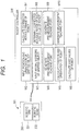
- functional blocks of the control device 200 are realized as shown in FIG. 1 , for example.
- the control device 200 is provided with the interfaces 1207 and 1208.
- the interface 1208 is used for controlling communication with the robotic arm 301.
- the CPU 1201 can cause the robotic arm 301 to execute a robot action in response to a robot program or the like taught in advance, by transmitting a control signal in conformity with a given signal format through the interface 1208.
- the interface 1207 is used for communication with a teaching device such as the teaching pendant 1300 (or with a different robot control device).
- Each of these interfaces 1207 and 1208 is formed from an arbitrary communication interface (such as a parallel communication interface or a serial communication interface) as described above.
- the network interface (NIF) 1206 is used for communication with a different control terminal (not shown), the different robot control device, a server on a network, and the like.
- This network interface 1206 can adopt various network communication methods through wired and wireless connection, such as IEEE802.3 in the wired connection and IEEE802.11 and 802.15 in the wireless connection. Note that the communication with the robotic arm 301 as well as a robot operation device (such as the teaching pendant 1300) may be conducted entirely through the network interface 1206.
- the robot apparatus 300 in FIG. 17 is provided with the teaching pendant 1300 serving as the teaching device which teaches teaching points for activating the robotic arm 301.
- the teaching pendant 1300 includes a keyboard (or any of a touch panel, an operation dial, and the like) operable in accordance with operation methods such as a step operation and a jog operation.
- the teaching pendant 1300 is configured to be capable of programming (teaching) an action of the robotic arm 301 and modifying the robot control data (the robot program) that has been taught in an actual installation environment.
- FIG. 16 shows a configuration example of an operation screen of the teaching pendant 1300.
- Operating keys 1301 and 1302 used for turning the joints J1 to J6 of the robotic arm 301 respectively in + and - directions, for example, are disposed on the operation screen of the teaching pendant 1300 in FIG. 16 .
- a central part of the operation screen of the teaching pendant 1300 is formed of a touch panel 1303.
- This touch panel 1303 is formed by disposing an operation panel on an LCD display unit, where the operation panel is designed to accept operation inputs such as tap (touch) and swipe (drag) operations.
- touch panel 1303 it is possible to construct a user interface configured to display keyboards and the like on the LCD display unit and to allow an operator to directly operate such a display section, for example.
- the touch panel 1303 of the teaching pendant 1300 in FIG. 16 displays display outputs and operation buttons as indicated with reference signs 1304, 1305, 1306, 1307, and so forth.
- the user interface constructed by these display items on the touch panel 1303 in FIG. 16 will be explained in connection with robot control to be described later.
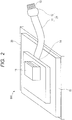
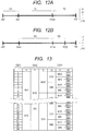
- FIG. 2 shows an example of a workpiece 800 as a target for assembly (attachment) manipulation by a gripping device such as the robotic hand 302 of the robotic arm 301.
- the workpiece 800 being a work target includes a board 15, a connector-attached cable 21 with its base end portion 14 being attached to the board 15, and a connector 16.
- the connector-attached cable 21 is drawn out of the board 15 in this example, the connector-attached cable 21 may be drawn out of a different member (not shown) instead.
- the connector-attached cable 21 includes a cable 11, and a connector 12 being a cable-side connector formed at a front end portion of the cable 11.
- a front end portion 13 in a longitudinal direction of the connector-attached cable 21 constitutes the connector 12.
- the cable 11 is made of a (flexible) flat cable, for instance.
- FIG. 3 shows an example of work to manufacture an article by connecting the front end portion 13 in the longitudinal direction of the connector-attached cable 21 having the above-described configuration to the connector 16.
- the robotic hand 302 of the robotic arm 301 includes a pair of fingers 303 and 304 for a gripping operation, which are provided at a front end of the robotic hand 302.
- control device 200 performs manipulation to grip the connector 12 on the connector-attached cable 21 side with the fingers 303 and 304 of the robotic hand 302, and then to connect the connector 12 to the connector 16 on the board 15 side as illustrated in FIGS. 4A to 4C , for example.
- the front end portion 13 in the longitudinal direction of the connector-attached cable 21 is gripped with the fingers 303 and 304 of the robotic hand 302.
- manipulation as shown in FIG. 4B is required if the cable 11 formed of a flat cable or the like assumes a straight orientation (shape) as illustrated in FIG. 4A .
- the control device 200 controls the robotic arm 301 in such a way as to turn the orientation of the connector 12 (the front end portion 13 of the connector-attached cable 21) gripped with the robotic hand 302 as shown in FIG. 4B , thereby directing the connector 12 toward the connector 16.
- the connector 12 is brought into engagement with (fitted into, inserted into, etc.) the connector 16 as shown in FIG. 4C .
- the position and orientation of the connector 12 need to be controlled when bringing the connectors 12 and 16 into engagement such that a projection and a recess of the connectors are aligned with each other.
- the position and the orientation of the connector 12 need to be aligned with the direction to insert the connector 16.
- the center 23 (the central axis) of the connector 16 needs to be aligned with the center 22 (the center axis) of the front end portion 13 in the longitudinal direction of the connector-attached cable 21.
- XY-coordinate systems used in assembly control conducted by the robot apparatus 300 is shown on an upper left part in FIG. 5 .
- This XY-coordinate system is a global coordinate system that is substantially parallel to a plane on which the board 15 is disposed, for example.
- the position and the orientation of the gripped object are corrected by applying a measurement result obtained by using the measurement device such as the visual sensor 500.
- the gripped object the front end portion 13 of the connector-attached cable 21
- the position and the orientation of the gripped object do not always establish an ideal positional relation with the connector 16 as shown in FIG. 6A .
- the gripped position (the gripped orientation) thereof may vary as shown in FIGS. 6B and 6C .
- the gripped position (the gripped orientation) thereof may vary as shown in FIGS. 6B and 6C .
- a region to be gripped with the fingers 303 and 304 of the robotic hand 302 may be displaced in another case.
- Those errors in the gripped position are caused by the effect of individual differences including a manufacturing error of the connector-attached cable 21, a position of attachment, bending and torsion of the cable 11, and so forth.
- FIG. 7 shows a state of shooting an image by using the visual sensor 500 while gripping the connector 12 with the robotic hand 302 at the position and the orientation illustrated in FIG. 4B , for example.
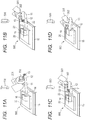
- FIGS. 11A to 11D show states of activating position-orientation correction processing on the gripped object (the connector 12 as well as the front end portion 13 of the connector-attached cable 21) by using measurement (shooting) results of the visual sensor 500 at the time of performing a connector attachment operation equivalent to the illustration in FIGS. 4A to 4C .
- FIGS. 11A and 11B correspond to the states illustrated in FIGS. 4A and 4B , respectively.
- the center 22 (the central axis) of the connector 12 that is, the front end portion 13 in the longitudinal direction of the connector-attached cable 21, is tilted with respect to the center 23 (the central axis) of the connector 16, and these axes are not aligned (do not coincide) with each other.
- the gripped connector 12 is tilted in a horizontal (XY) plane with respect to the fingers 303 and 304 of the robotic hand 302, and a front end of the connector 12 is tilted downward.
- the control device 200 can calculate the position and the orientation of the connector 12 gripped with the robotic hand 302, such as the position and the orientation of the center 22, by using an image shot with the visual sensor 500. Then, the control device 200 can correct subsequent control of the position and the orientation of the robotic arm 301 at the time of bringing both of the connectors 12 and 16 into engagement as illustrated in FIGS. 11C and 11D , by using a result of analysis of the image shot with the visual sensor 500.
- an attachment step that is, a step of connecting the connectors 12 and 16 is completed by pushing the connector 12 into the connector 16 with the robotic arm 301.
- the above-mentioned position-orientation control error may occur in the course of actions of the robotic arm 301 ( FIGS. 11C and 11D ) at the time of bringing both of the connectors 12 and 16 into engagement as corrected by the control device 200 while using the result of analysis of the image shot with the visual sensor 500.
- the correction takes place in such a way as to reverse rotation (to cause reverse rotation) of a certain one of the joints (J1 to J6) in the course of a corrected action of the robotic arm 301.
- Timing for performing the shooting (the measurement) with the visual sensor 500 can be determined based on an operation conducted by an operator with the teaching pendant 1300, for example.
- the control device 200 may automatically determine the timing while using a specific operation of the teaching pendant 1300 as a trigger.
- the above-mentioned position-orientation control error may occur when the correction takes place in such a way as to reverse the rotation (to cause the reverse rotation) of the certain one of the joints (J1 to J6) in the robotic arm 301 in the course of the shooting (the measurement) with the visual sensor 500.
- the position-orientation control error is attributed to a backlash of the drive (transmission) system of a certain one of the joints (J1 to J6) caused by the reversal of the rotation (the reverse rotation) of the certain joint.
- an operation to connect the connectors 12 and 16 may fail or a forcible connector inserting operation may take place and end up in failure to establish a normal connection status.
- this Example 1 provides a configuration to enable a corrective action in the correction of the position-orientation control of the robotic arm 301 to be conducted in response to the shooting (the measurement) with the visual sensor 500, with which the occurrence of the position-orientation control error attributed to the reversal of the rotation (the reverse rotation) of the certain one of the joints (J1 to J6) is avoidable.
- the correction of the position-orientation control of the robotic arm 301 to be conducted in response to the shooting (the measurement) with the visual sensor 500 is naturally conducted in terms of the position and the orientation of the gripped object (as well as the arm) when the shooting (the measurement) with the visual sensor 500 takes place. Accordingly, the timing of the shooting (the measurement) with the visual sensor 500 and the position and the orientation of the gripped object (and the arm) at that timing are controlled in this Example 1.
- the robot apparatus 300 includes the robotic arm 301 provided with the gripping device (the robotic hand 302) capable of changing its position or orientation by using the joints.
- the robot apparatus 300 includes the measurement device (the visual sensor 500) which measures the position or the orientation at a measurement teaching point of the gripped object (the connector 12) gripped with the gripping device (the robotic hand 302).
- the control device 200 of the robot apparatus 300 controls the position or the orientation when the gripped object (the connector 12) is attached to the attachment target object (the connector 16) being the target for attachment at an attachment teaching point that is corrected based on the measurement result by the measurement device. Moreover, in the control method of this Example 1, the control device 200 executes a measurement teaching point determination process of determining the measurement teaching point such that the driving direction of each of the joints (J1 to J6) from the measurement teaching point to the attachment teaching point mentioned above is set to the definite driving direction.
- the control device 200 of the robot apparatus 300 acquires a pre-measurement teaching point (a pre-measurement teaching point determination process) where the robotic arm 301 causes the gripped object (the connector 12) gripped with the robotic hand 302 to pass through in advance of the measurement teaching point.
- the pre-measurement teaching point determination process the pre-measurement teaching point is determined such that the driving direction of each of the joints from the pre-measurement teaching point to the measurement teaching point where the measurement with the visual sensor 500 takes place is set to the definite driving direction.
- the gripped object is moved to the measurement teaching point via the pre-measurement teaching point determined in the pre-measurement teaching point determination process.
- the control to cause the robot apparatus 300 to determine the measurement teaching point (the teaching point at which the measurement with the visual sensor 500 takes place) such that it is possible to create the corrective action which can avoid the occurrence of the reversal of the rotation (the reverse rotation) of each of the joints (J1 to J6) of the robotic arm 301 as mentioned above will be described below in further detail.
- Workpieces 800 or more specifically, the workpieces 800 each provided with the connector-attached cable 21, the board 15 to which the connector-attached cable 21 is attached, and the connector 16 serving as a connection target to the connector 12, are sequentially supplied onto a work table 20 by using a not-illustrated supply-conveyance unit.
- Each of these workpieces 800 is roughly positioned on the work table 20. Accordingly, it is possible to achieve substantially constant control of a control position of the base end portion 14 (a base) of the connector-attached cable 21 (the cable 11) as well as a control position in the vicinity thereof. However, a variation in position is gradually increased toward the front end portion 13 of the connector-attached cable 21 due to the effects of bending, torsion and the like of the cable 11. For this reason, even when the board 15 of each workpiece 800 is positioned on the work table 20, the position and the orientation of the front end portion 13 of the connector-attached cable 21 before being gripped are likely to vary over relatively wide ranges as shown in FIGS. 6B and 6C .
- the robotic hand 302 is used to pinch an intermediate region near the base end portion 14 of the connector-attached cable 21. Then, a pinching amount of the robotic hand 302 is thought to be set with such a clearance that enables the robotic hand 302 in the pinching (gripping) state to move to the connector 12 of the connector-attached cable 21 while sliding thereon.
- a possible option is to provide a confinement unit that confines error ranges of the position and the orientation of the gripped object (the connector 12), which is in the state of being gripped with the gripping device (the robotic hand 302), with respect to the gripping device to predetermined ranges.
- the fingers 303 and 304 of the robotic hand 302 are provided with confinement members at such positions and orientations as represented by projections 305 and 306.
- the confinement unit As shown in FIG. 8 , it is possible to confine the displacement of the front end portion 13 from the robot apparatus 300 at the time of insertion of the front end portion 13 within a predetermined error range in advance, and thus to reduce a control burden for the robot control to be described later.
- the robotic hand 302 with such a structure that can keep the connector 12 (or part of the connector-attached cable 21) pinched between the fingers 303 and 304 from sliding during the action to connect the connector 12 to the connector 16.
- a possible option for example, is to form opposed surfaces of the fingers 303 and 304 by using a material having a high friction coefficient such as a rubber material. This makes it possible to prevent or suppress the misalignment of the relative positions and the relative orientations between the front end portion 13 of the connector-attached cable 21 and the fingers 303 and 304 during the action of the robotic arm 301 to change the orientations of the fingers 303 and 304.
- the visual sensor 500 naturally has a measurement range (such as an angle of view) to allow the visual sensor 500 to shoot (measure) the connector 12 of the connector-attached cable 21 and the connector 16 of the robotic hand 302 at the same time.
- a measurement range such as an angle of view
- control functions of the control device 200 are thought to be constructed by respective functions as shown in FIG. 1 , for example.
- the robot apparatus 300 provided with the robotic arm 301 and the robotic hand 302 in FIG. 17 are illustrated as a single block.
- the functions of respective control blocks in FIG. 1 are formed of the storage units (the ROM 1202 and the RAM 1203) and operating functions (of the CPU 1201) of the control device 200 except for a hardware configuration (W1) thereof.
- the robot control of this Example 1 performs the control to correct the relative positions and the relative orientations between the attachment target object (the connector 16) and the object (the connector 12) gripped with the robotic hand 302 to be moved via the pre-measurement teaching point, the measurement teaching point, and the attachment teaching point.
- the term “teaching point” represents a physical amount and control information corresponding to the position and the orientation of the entire robotic arm 301 inclusive of the robotic hand 302.
- Such a teaching point may be expressed, for example, by the position and the orientation of a reference region (a reference point) of the robot such as the center (the central axis) of a flange surface where the robotic hand 302 is attached to the robotic arm 301.
- a reference region a reference point
- the above-mentioned expression “moved via the teaching point” means that the aforementioned reference region (the reference point) of the robot undergoes the position and the orientation of each teaching point.
- "teaching" manipulation by using the teaching pendant 1300 adopts a manipulation method of moving the position and the orientation of the reference region (the reference point) mentioned above by way of a manipulation unit such as a jog button (details of which are not illustrated) disposed on the teaching pendant 1300 shown in FIG. 17 .
- the position and the orientation are determined based on an axis value (which is a rotational angle in the case of a rotary joint) of each of the joints (J1 to J6).
- the control device 200 conducts so-called kinematics calculation starting from the axis value of each of the joints (J1 to J6), thereby acquiring the corresponding teaching point, that is, the position and the orientation occupied by the reference region (the reference point) of the robot.
- the teaching point being a control target that is, the axis value of each of the joints (J1 to J6) for achieving the position and the orientation to be occupied by the reference region (the reference point) of the robot, is acquired by conducting so-called inverse kinematics calculation starting from the teaching point.
- a certain teaching point is uniquely determined by conducting the kinematics calculation based on the axis value of each of the joints (J1 to J6).
- the number of combinations of the axis values of the respective joints (J1 to J6) to be obtained by the inverse kinematics calculation so as to achieve the certain teaching point is not necessarily limited only to one.
- the control method of this Example 1 is formed from the functions illustrated in blocks that are denoted by reference signs W1 to W10 as shown in FIG. 1 , for example.
- reference sign W1 corresponds to a movement unit that moves the gripped object (such as the connector 12) gripped with the robot apparatus 300.
- the movement unit W1 is formed from drive sources (such as servo motors) for the respective joints (J1 to J6) of the robotic arm 301 and for the fingers 303 and 304 of the robotic hand 302, for example.
- reference sign W2 denotes the measurement device that measures one or both of the position and the orientation of the gripped object (the connector 12).
- the measurement device W2 corresponds to the visual sensor 500.
- reference sign W3 denotes a unit to input maximum and minimum error ranges of the relative position and the relative orientation of the gripped object (the connector 12) in the gripped state with respect to the robotic hand 302.
- the unit W3 may for instance be table data of specification information prepared in the ROM 1202 and the like.
- the unit W3 corresponds to step S100 in FIG. 9 to be described later.
- the maximum and minimum error ranges of the relative position and the relative orientation of the gripped object (the connector 12) in the gripped state with respect to the robotic hand 302 can be calculated in advance based on physical dimensions of and shape information on the confinement unit such as the projections 305 and 306 in FIG. 8 . Then, the maximum and minimum error ranges of the relative position and the relative orientation of the gripped object (the connector 12) in the gripped state with respect to the robotic hand 302 thus obtained are stored in the ROM 1202 and the like.
- the confinement unit By providing the confinement unit to confine the maximum and minimum error ranges of the relative position and the relative orientation of the gripped object (the connector 12) in the gripped state with respect to the robotic hand 302 as shown in FIG. 8 , it is possible to reduce an amount of calculation by the control device 200 at the time of acquisition of the corrected movable range to be described later.
- reference sign W4 denotes a unit to acquire a teaching point ( FIG. 11C , for example) used to move the robotic arm 301, the measurement teaching point ( FIG. 11B , for example), and a via-point ( FIG. 11A , for example) as the pre-measurement teaching point when there is no position (orientation) error of the gripped object.
- the unit W4 can be realized, for example, by a teaching operation to teach the respective teaching points mentioned above to be conducted by the operator using the teaching pendant 1300.
- the respective teaching points mentioned above may be stored in the ROM 1202 as setting information in advance, depending on ranges of specifications regarding work accuracy of the workpiece 800, conveyance (supply) accuracy of the workpiece 800, control accuracy of the robotic arm 301, and so forth.
- the unit W4 corresponds to step S200 in FIG. 9 to be described later.
- reference sign W5 denotes a unit to obtain the position and the orientation to be taken by the robotic arm 301 after the corrective action at the attachment teaching point ( FIG. 11C , for example) depending on the maximum and minimum error ranges of the position and the orientation of the gripped object (the connector 12) acquired by the unit W3.
- reference sign W6 denotes a unit to obtain the axis value of each of the joints (J1 to J6) of the robotic arm 301 at a specific position and a specific orientation (the teaching point) of the robotic arm 301.
- the unit W6 can be realized, for example, by causing the CPU 1201 of the control device 200 to perform calculation (the inverse kinematic calculation) of the axis value (which is the rotational angle in the case of the rotary joint) of each of the joints (J1 to J6) based on the specific position and the specific orientation (the teaching point) of the robotic arm 301.
- the unit W6 corresponds to step S400 in FIG. 9 to be described later.
- reference sign W7 denotes a unit to obtain the possible corrected movable range of the axis value (which is the rotational angle in the case of the rotary joint) in terms of each of the joints (J1 to J6) of the robotic arm 301 (a corrected movable range acquisition process).
- the corrected movable range corresponds to a range of possible axis values applicable to the certain one of the joints (J1 to J6) on the way to the teaching point ( FIG. 11C ) at a destination of the robotic arm 301 when there is no error, the range corresponding to the maximum and minimum error ranges (the unit W3) of the position and the orientation of the gripped object (the connector 12).
- the CPU 1201 of the control device 200 performs the calculation based on the above-mentioned maximum and minimum error ranges and on the teaching point ( FIG. 11C ) at the destination of the robotic arm 301 when there is no error.
- the unit W7 corresponds to step S600 in FIG. 9 to be described later.
- the CPU 1201 can acquire a list of teaching points located on a trajectory to move the robot to the teaching point.
- the list of teaching points thus acquired can be formed in a linked list format, for example, and stored in the RAM 1203 as with the case of storing a binary tree and graph data.
- the CPU 1201 can obtain the possible axis value of a certain one of the joints (J1 to J6) corresponding to each teaching point by the inverse kinematics calculation of the unit W6 by referring to the list of teaching points directed to the teaching point ( FIG.
- the range of possible axis values applicable to the certain one of the joints (J1 to J6) during the action to be directed to the teaching point ( FIG. 11C ) at the destination of the robotic arm 301 when there is no error is acquired as the corrected movable range of the certain joint.
- the corrected movable range thus acquired is supposed to realize the trajectory of the teaching points of the robotic arm 301 corresponding thereto only with the rotary drive of the certain joint in one direction.
- the certain joint causes the reverse rotation on a certain trajectory of the teaching points as a result of the inverse kinematics calculation (W6)
- the certain trajectory of the teaching points in the list of the teaching points is to be excluded from the target to be acquired as the corrected movable range.
- reference sign W8 denotes a determination unit to determine whether or not the axis value of each of the joints (J1 to J6) corresponding to a certain via-point, such as the pre-measurement teaching point, falls within the corrected movable range (W7).
- the determination unit W8 corresponds to steps S700 and S800 in FIG. 9 to be described later.
- reference sign W9 corresponds to a control function applicable to the case (W8) where the axis value of each of the joints (J1 to J6) corresponding to a certain via-point such as the pre-measurement teaching point falls within the corrected movable range (W7).
- the unit W9 represents a control unit which provides a new teaching point in such a range where each axis value falls out of the corrected movable range during the movement from a pre-measurement teaching point to the attachment teaching point ( FIG. 11C ), and determines this teaching point as the pre-measurement teaching point immediately preceding to the measurement teaching point.
- the control unit W9 corresponds to steps S1000 and S1100 in FIG. 9 to be described later, and the "via-point" in these steps corresponds to the above-mentioned "pre-measurement point immediately preceding to the measurement teaching point".
- reference sign W10 denotes a unit to provide another new teaching point in such a range where each axis value falls out of the corrected movable range during the movement from the pre-measurement teaching point (W9) to the attachment teaching point ( FIG. 11C ), and to define this teaching point as the measurement teaching point to be measured with the visual sensor 500.
- the unit W10 corresponds to step S1200 in FIG. 9 to be described later.
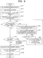
- FIG. 9 shows an example of robot control procedures for realizing the respective control functions (W1 to W10) in FIG. 1 described above in this Example 1.
- the control procedures in FIG. 9 can be stored in the ROM 1202 or the external storage device 1204 as a control program executable by the control device 200. Now, the control procedures in FIG. 9 will be described below in detail.
- the workpiece 800 to be handled by the robotic arm 301 is assumed to have the configuration as illustrated in FIGS. 2 to 7 .
- the confinement unit configured to suppress the variations (the error ranges) of the position and the orientation of the gripped object (the connector 12) are preferably disposed on the robotic hand 302 as shown in FIG. 8 .
- step S100 in FIG. 9 the CPU 1201 of the control device 200 sets the error ranges ( FIGS. 5 , and 6A to 6C ) of the position and the orientation of the center 22 of the front end portion 13 of the connector-attached cable 21 with respect to the center 23 of the connector 16.
- the error ranges of the workpiece 800 are values derived from a product error, attachment accuracy, positioning accuracy, and the like of the connector-attached cable 21, which are stored in the ROM 1202 and the like in advance.
- the CPU 1201 reads the values therefrom. As shown in FIG.
- the error ranges of the workpiece 800 are expressed by coordinate information in terms of three axes of XYZ axes and information on amounts of rotation around the three axes, namely, X, Y, Z (position information 1401: by the millimeter), and rX, rY, rZ (orientation information 1402: by the degrees (of the angle)).
- X, Y, Z position information 1401: by the millimeter
- rX, rY, rZ orientation information 1402: by the degrees (of the angle)
- teaching points to let the robotic arm 301 pass (pass through) in the manipulation to attach the connectors 12 and 16 are set in step S200.
- the setting of the teaching points is either automatically performed by the CPU 1201 using design information on the workpiece 800 or performed by manipulation of the teaching pendant 1300 by the operator.
- Teaching points to be set at this stage include the following two types of teaching points.
- the first teaching point represents the position and the orientation of the robotic arm 301 in the case where the centers 22 and 23 of the connectors 12 and 16 coincide with each other as shown in FIG. 11C , and a required correction amount is therefore zero.
- the other teaching point corresponds to the teaching point immediately preceding to the measurement teaching point to measure a relative position relation between the center 22 of the connector 12 and the center 23 of the connector 16 with the visual sensor 500 as shown in FIG. 11B , and this teaching point represents the position and the orientation of the robotic arm 301 shown in FIG. 11A , for example.
- the measurement teaching point is acquired by the robot control of this Example 1.
- the pre-measurement teaching point does not always have to represent the position and the orientation shown in FIG. 11A .
- step S300 the CPU 1201 sets attachment correction ranges ( FIG. 10B ) corresponding to correction ranges of the position and the orientation to be carried out in an attachment operation to be described later based on the error ranges ( FIG. 10A ) of the position and the orientation of the workpiece 800 set in step S100.
- position information 1403 and orientation information 1404 in the attachment correction ranges represents the error ranges (variation ranges of the gripped workpiece) of the position and the orientation in FIG. 10A , with positive and negative signs therein being inverted.
- the values of the error ranges ( FIG. 10A ) and the values of the attachment correction ranges ( FIG. 10B ) correspond to one another based on the assumption that these ranges adopt the same coordinate system.
- step S400 the inverse kinematics calculation is conducted in terms of all of the positions and the orientations (all the teaching points) of the robot that can be taken within the attachment correction ranges (MAX to MIN) in FIG. 10B which are obtained in step S300.
- the axis value of each of the joints (J1 to J6) of the robotic arm 301 at each position and each orientation (each teaching point) is acquired.
- the axis value of each of the joints (J1 to J6) at each of the teaching points may be acquired by searching the teaching points on a teaching point trajectory in a space corresponding to the attachment correction ranges ( FIG. 10B ) by using arbitrary step amount.
- step S500 corresponds to loop control for carrying out processing from steps S600 to S900 in terms of each of the joints (J1 to J6) of the robotic arm 301 (as many times as the number of the axes).
- steps S600 to S900 is carried out on each of the joints J1 to J6.
- a general expression "n" is used as an index to identify each of the joints J1 to J6 (where n is an integer from 1 to 6).
- the corrected movable range J[n] of the axis value (which is the rotational angle in the case of the rotary joint) of the joint Jn (any of J1 to J6) being processed is calculated in the first step S600 of this loop.
- this corrected movable range J[n] (1405) is calculated as the range of the axis value of the joint Jn at the position and the orientation of the robotic arm 301, which can be taken within the correction ranges corresponding to the attachment correction ranges ( FIG. 10B ) obtained in step S400.
- the (maximum) movable range (defined as A, for example) of a certain joint (Jn) of the robot satisfies -180° ⁇ A ⁇ 180°.
- a range corresponding to the attachment correction range ( FIG. 10B ) calculated by the inverse kinematics calculation in step S400 is assumed to be R2 (from ⁇ min to ⁇ max).
- the corrected movable range J[n] corresponding to the attachment correction range of the joint (Jn) is equivalent to the range R2, namely, ⁇ min ⁇ J[n] ⁇ ⁇ max.
- step S700 the CPU 1201 checks overlap between the axis value of the joint (Jn) at the pre-measurement teaching point acquired in step S200 and the corrected movable range.
- the corrected movable range J[n] of the joint (Jn) obtained in step S600 is assumed to fall within the range R2 in FIG. 12A , for example.
- the check processing in step S700 corresponds to processing to check whether or not the axis value of the joint (Jn) (acquired by the inverse kinematics calculation and) corresponding to the pre-measurement teaching point acquired in step S200 falls within (overlaps) the range R2 of the joint axis.
- step S800 it is determined in step S800 whether or not there is the occurrence of the overlap in step S700, and step S900 is executed if there is the occurrence of the overlap. If there is no occurrence of the overlap in step S700, that is, when the axis value of the joint (Jn) (to be acquired by the inverse kinematics calculation and) corresponding to the pre-measurement teaching point falls out of the corrected movable range J[n], the loop processing of the relevant joint (Jn) is terminated (the processing returns to step S500).
- step S900 the CPU 1201 executes processing applicable to the case where the result in step S700 turns out that the axis value of the joint (Jn) at the pre-measurement teaching point falls within the corrected movable range J[n].
- a range Jt[n] of the via-point to be passed through as the new pre-measurement teaching point outside the corrected movable range J[n] is calculated in step S900.
- the corrected movable range J[n] of the joint (Jn) is equivalent to the range R2 as shown in FIG.
- the range Jt[n] of the via-point is defined as ranges outside the range R2, namely, - 180° ⁇ Jt[n] ⁇ ⁇ min and ⁇ max ⁇ Jt[n] ⁇ 180°.
- step S1000 it is determined whether or not there is the occurrence of the overlap in the determination concerning the pre-measurement teaching point in step S800.
- Step S1100 is executed when there is the occurrence of the overlap in step S800.
- step S1100 in terms of all of the joints (J1 to J6), the via-point in a via-point range (Jt[n]) satisfying the condition of being "outside the corrected movable range (R2 in FIG. 12A )" calculated in step S900 is acquired as the new pre-measurement teaching point.
- the processing to acquire the via-point satisfying this condition as the new pre-measurement teaching point is thought to be conducted by automatic calculation of the CPU 1201, for example.
- the range outside the corrected movable range calculated in step S900 is assumed to be any of the above-mentioned ranges (R1 and R2) of -180° ⁇ Jt[n] ⁇ ⁇ min and ⁇ max ⁇ Jt[n] ⁇ 180°, for example.
- the CPU 1201 is caused to select one of the via-points within any of the via-point ranges (R1 and R2) and to acquire the selected via-point as the new pre-measurement teaching point. At this time, however, the CPU 1201 is controlled so as not to acquire the via-point within any of the two via-point ranges (R1 and R2), which establishes an angular relation that causes the relevant joint Jn to enter the corrected movable range (R2 in FIG. 12A ) in an opposite direction to the rotational direction of the joint Jn in the corrected movable range in the actual corrective action.
- the processing to acquire the via-point as the new pre-measurement teaching point in step S1100 can also be carried out by teaching manipulation of the operator using the teaching pendant 1300.
- the operator is caused to perform the teaching operation by using the teaching pendant 1300 so as to teach an arbitrary via-point (a teaching point).
- the CPU 1201 determines whether or not the via-point (the teaching point) taught from the teaching pendant 1300 satisfies the condition of the above-mentioned via-point range (R1 or R2).
- the CPU 1201 acquires the via-point (the teaching point) taught from the teaching pendant 1300 as the new pre-measurement teaching point when the condition of the above-mentioned via-point range (R1 or R2) is satisfied.
- the CPU 1201 performs the calculation to acquire the measurement range.
- the measurement range means a range R4 between an axis value Jb[n] of a certain joint (Jn) corresponding to the pre-measurement teaching point acquired in step S1100 and the corrected movable range R2 of the certain joint (Jn).
- the CPU 1201 acquires this range R4 as a measurement range (R4).
- step S1300 the position and the orientation of the robotic arm 301 at the time of performing the measurement with the visual sensor 500 in order to correct the operation to attach the connectors 12 and 16, that is, the measurement teaching point ( FIG. 11B ) is acquired.
- the measurement teaching point is acquired from within the measurement range (R4 in FIG. 12B ) calculated in step S1200.
- the acquisition of the measurement teaching point is also thought to be conducted by automatic calculation of the CPU 1201, for example.
- the CPU 1201 is caused to select one of teaching points within the measurement range (R4) and to acquire the selected teaching point as the measurement teaching point.
- the acquisition of the measurement teaching point in step S1300 can also be carried out by teaching manipulation of the operator using the teaching pendant 1300.
- the user interface as shown in FIG. 16 can be adopted to teaching pendant 1300 in order to acquire (teach) the measurement teaching point, for example.
- An input device to allow the operator to input candidates for the measurement teaching point (or the pre-measurement teaching point) is arranged on the teaching pendant 1300 (the teaching device).
- the input device is formed from the operating keys 1301 and 1302, and the touch panel 1303.
- an output device to output information on whether or not any of the candidates for the measurement teaching point (or the pre-measurement teaching point) inputted with the input device satisfies the above-described relation with the corrected movable range is arranged on the teaching pendant 1300 (the teaching device).
- the output device is formed from (a display unit of) the touch panel 1303.
- the operator activates the respective joints (J1 to J6) of the robotic arm 301 by using the operating keys 1301 and 1302, for example, thereby moving (the reference region, for example, of) the robotic arm 301 to the desired teaching point (the position and the orientation).
- the desired teaching point the position and the orientation
- numerical input keys (not shown) and the like are additionally provided to the teaching pendant 1300, it is also possible to adopt an operating method of designating the desired teaching point by inputting a numerical value representing the rotational angle of each of the joints (J1 to J6).
- a mode display section 1304 such as "teaching of measurement teaching points" is displayed on an upper part of the touch panel 1303.
- a propriety display section 1307 indicating propriety of the teaching point designated by moving the robotic arm 301 (or designated by inputting the numerical values), for example, is displayed at a lower part of the touch panel 1303.
- the propriety display section 1307 includes: angle subsections (display subsections in rectangular frames) of the respective joints (J1 to J6) corresponding to the designated teaching point; and appropriateness display subsections (in circles) located therebelow and indicating "OK” (appropriate) or "NG” (inappropriate).
- the appropriateness display subsections (in circles) in the propriety display section 1307 are configured to indicate whether or not the axis values of the respective joints (J1 to J6) satisfy the measurement range (R4 in FIG. 12B ) calculated in step S1200.
- a numerical value display subsection 1306 to display the ranges of the axis values of the respective joints (J1 to J6) corresponding to the measurement range (R4 in FIG. 12B ) is provided below the propriety display section 1307.
- the appropriateness display subsections (in circles) in the propriety display section 1307 indicate that the axis values of the joints J1, J3, J4, and J5 satisfy the measurement ranges (R4 in FIG. 12B ) for the respective axes (appropriate).
- the appropriateness display subsections (in circles) in the propriety display section 1307 indicate that the axis values of the joints J2 and J6 do not satisfy the measurement ranges (R4 in FIG. 12B ) for the respective axes (no and inappropriate).
- this display example of the user interface in FIG. 16 shows a state where the teaching point (the position and the orientation) of the robotic arm 301 is inappropriate as the measurement teaching point.
- the touch panel 1303 displays the information as shown in FIG. 16
- the operator designates a different teaching point by repeating the teaching operation.
- the CPU 1201 enables an input operation of a confirmation key display section 1305 (a virtual key) indicating "confirmation of measurement teaching points" at a lower part of the touch panel 1303 when all the appropriateness display subsections (in circles) in the propriety display section 1307 indicate "OK" (appropriate).
- the confirmation key display section 1305 becomes operable, the operator can confirm the teaching point as the measurement teaching point by operating the confirmation key display section 1305.
- the same user interface as that in FIG. 16 can also be used when acquiring the pre-measurement teaching point in step S1100 described above.
- character strings in the mode display section 1304 and in the confirmation key display section 1305 may be changed from “measurement teaching points” in FIG. 16 into “pre-measurement teaching points” as appropriate.
- step S1400 After the measurement teaching point is acquired as described above, it is possible to cause the robotic arm 301 to execute an attachment action in step S1400 and so on, inclusive of the corrective action based on the measurement with the visual sensor 500 at the measurement teaching position thus acquired.
- the visual sensor 500 is caused to perform the measurement by using the pre-measurement teaching point and the measurement teaching point taught in steps S1100 and S1300, and the robotic arm 301 is caused to execute the attachment action inclusive of the corrective action based on the measurement.
- the CPU 1201 measures the workpiece 800 with the visual sensor 500 at the acquired measurement teaching point, and then corrects the positon and the orientation of the robotic arm 301 based on an analysis of measurement images in such a way as to align the centers 22 and 23 of the connectors 12 and 16 with each other. Thereafter, the CPU 1201 causes the robotic arm 301 to perform an inserting operation involving the connectors 12 and 16. Thus, it is possible to execute the attachment of the connectors 12 and 16 reliably and accurately.
- step S1400 in FIG. 9 may also be regarded as corresponding to a general assembly process in which numerous workpieces 800 are repeatedly processed by automatic execution.
- a process to acquire the pre-measurement teaching point and the measurement teaching point prior to the workpiece attachment operation in step S1400 may be regarded as a teaching process to program the general assembly process.
- step S1400 is repeatedly executed by using the pre-measurement teaching point and the measurement teaching point determined in the teaching process to program the general assembly process. Then, the manipulation to attach the connectors 12 and 16 of each of the workpieces 800 is corrected every time based on the actual measurement with the visual sensor 500.
- the correction processing to align the centers 22 and 23 of the connectors 12 and 16 with each other is carried out in response to a grip error that may reside in each of the workpieces 800.
- the possible corrected movable range of the axis value of the certain one of joints toward the attachment teaching point is obtained based on the possible error ranges of the relative position and the relative orientation of the gripped object (the connector 12) gripped with the robotic hand 302 (the corrected movable range acquisition process).
- the teaching point included in the range outside the corrected movable range is acquired as the pre-measurement teaching point based on the axis value of the relevant joint corresponding to the acquired corrected movable range.
- the teaching point included in the range between the corrected movable range and the pre-measurement teaching point is acquired as the measurement teaching point based on the axis value of the relevant joint corresponding to the acquired corrected movable range.
- the via-point outside the corrected movable range is acquired as the pre-measurement teaching point, and the measurement teaching point where the measurement with the visual sensor 500 takes place is acquired at a point between the pre-measurement teaching point and the corrected movable range where the corrective action based on the measurement takes place.
- the robotic arm 301 is moved from the pre-measurement teaching point to the measurement teaching point, and is then caused to execute the action in the corrected movable range based on the measurement conducted at the measurement teaching point with the visual sensor 500.
- Example 1 by performing the robot control as described above, it is possible to select the measurement teaching to perform the measurement with the visual sensor 500, so as to create the corrective action that can avoid the occurrence of the reversal of the rotation (the reverse rotation) of each of the joints (J1 to J6).
- the robotic arm 301 when the robotic arm 301 is moved from the pre-measurement teaching point to the measurement teaching point and further to the corrected movable range, the robotic arm 301 is controlled in such a way that a certain one (or all) of the joints is driven in the definite driving direction without causing the reverse rotation. For this reason, it is possible to properly suppress a control error attributed to a backlash of a drive system of each of the joints of the robotic arm 301, thereby manufacturing an article while conducting accurate and reliable workpiece attachment.
- a combination of the connector-attached cable 21 and the connector 16 has been shown above as an example of the workpiece 800.
- the above-described robot control technique is not limited by aspects of the workpieces to be manipulated.
- the robot control technique is applicable to an arbitrary robot apparatus as long as the robot apparatus is configured to correct a gripped workpiece in response to a result of measurement with the visual sensor 500.
- Example 2 of the present invention will be described.
- a hardware configuration and a basic control configuration of a robot apparatus in this Example 2 are assumed to be the same as those illustrated in the drawings in conjunction with the description of Example 1.
- Example 1 explains that the inverse kinematics calculation is to be conducted in terms of all the possible combinations of the positions and the orientations (the teaching points) of the robot within the attachment correction ranges (from MAX to MIN) in FIG. 10B obtained in step S300.
- this configuration may require the CPU 1201 of a high-performance type or require a high-capacity memory (such as the RAM 1203 and a virtual memory).
- step S400 of this Example 2 the inverse kinematics calculation is executed in terms of all the combinations involving only the maximum values and the minimum values (MAX and MIN) in position information 1502 and orientation information 1503 in the attachment correction ranges instead of all the possible positions and orientations in the attachment correction ranges in FIG. 10B .
- Example 3 robot apparatus control according to Example 3 of the present invention will be described.
- a hardware configuration and a basic control configuration of a robot apparatus are assumed to be the same as those illustrated in the drawings in conjunction with the description of Example 1.
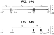
- Example 3 adopts a different method of acquiring the via-point range outside the corrected movable range (R2) in step S900 shown in FIG. 9 .
- measurement ranges acquired in step S1200 in FIG. 9 are different from those acquired in Example 1.
- Example 1 explains that when the range Jt[n] of the via-point (the pre-measurement teaching point) is equivalent to the corrected movable range (R2) in FIG. 12A , the range Jt[n] is defined as -180° ⁇ Jt[n] ⁇ ⁇ min and ⁇ max ⁇ Jt[n] ⁇ 180° (ranges R1 and R3) in step S900.
- a via-point (a pre-measurement teaching point) with which a joint drive amount from the via-point (the pre-measurement teaching point) to the measurement teaching point is rendered extremely small may be acquired (and taught) in the acquisition (and the teaching) of the pre-measurement teaching point.
- This case may lead to an action in which a backlash cannot be sufficiently moved to one side, and the measurement teaching point may be set up while a control error attributed to the backlash is still active, for example.
- the via-point range Jt[n] to be defined outside the corrected movable range (R2) is located on each of two outer sides of the corrected movable range (R2) at a distance away by at least the amount equivalent to the angle ⁇ b that corresponds to the backlash of the drive system of the joint.
- an amount of rotation of the joint drive system corresponding to the backlash can be obtained from numerical values of backlashes and the like in a catalog for a transmission used in the joint, and stored in the ROM 1202 and the like in advance.
- the via-point range Jt[n] is acquired as ranges R1' and R3' located on two outer sides of the corrected movable range (R2), while each range and the corrected movable range interposing a gap at an amount of the angle ⁇ b corresponding to the backlash.
- the via-point ranges (R1' and R3') are defined as -180° ⁇ Jt[n] ⁇ ⁇ min - ⁇ b and ⁇ max + ⁇ b ⁇ Jt[n] ⁇ 180°.
- a range (R4') of the measurement teaching point is defined as a range narrowed down by at least the amount of the angle ⁇ b corresponding to the backlash as shown in FIG. 14B due to the same reason.
- the via-point ranges (R1' and R3') and the range (R4') of the measurement teaching point are acquired based on a drive amount corresponding to the angle ⁇ b reflecting the backlash as mentioned above.
- the certain joint is controlled in such a way as to be driven in the definite direction at least by the drive amount corresponding to the backlash of the drive system.
- the certain joint is controlled in such a way as to be driven in the definite direction at least by the drive amount corresponding to the backlash of the drive system as well. Therefore, according to this Example 3, the robotic arm 301 can be moved without being affected by the control error attributed to the backlash of the joint drive system during the movement from the via-point (the pre-measurement teaching point) to the measurement teaching point or from the measurement teaching point to the corrected movable range.
- Example 4 robot apparatus control according to Example 4 of the present invention will be described.
- a hardware configuration and a basic control configuration of a robot apparatus are assumed to be the same as those illustrated in the drawings in conjunction with the description of Example 1.
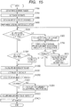
- FIG. 15 is a flowchart arranged by adding steps S1201 to S1204 to the control procedures in FIG. 9 .
- steps S100 to S1400 having already been explained in conjunction with Example 1 will be omitted, and only the processing in steps S1201 to S1204 will be explained instead.
- the additional steps S1201 to S1204 in FIG. 15 correspond to control to avoid interface (interface calculation) with an obstacle in an environment where the robot apparatus 300 is installed.
- an obstacle is an object other than the robot apparatus 300 in the environment where the robot apparatus 300 is installed as well as the workpiece 800 to be handled by the robot apparatus 300.
- Such an obstacle is possibly another robot, and other furniture and equipment in the room, for example.
- Obstacle range information that is, information concerning a spatial range occupied by the obstacle in the environment where the robot apparatus 300 is installed is set in step S1201 in FIG. 15 .
- the obstacle range information is expressed, for example, by a list of coordinate value corresponding to the space occupied by the obstacle in terms of a global coordinate system of the environment where the robot apparatus 300 is installed.
- the obstacle range information may adopt an arbitrary data storage format.
- An operator or an administrator can input the obstacle range information in advance by numerical value input or through a GUI operation depending on the condition of the environment to install the robot apparatus 300.
- the CPU 1201 may possibly generate the obstacle range information from a result of recognition of image information, for example, which is obtained by measuring the environment to install the robot apparatus 300 while using the visual sensor 500.
- the obstacle range information thus inputted or generated can be stored in the external storage device 1204, for example, at a stage before its use in the control in FIG. 15 . Then, prior to execution of the control in FIG. 15 , the obstacle range information is developed in the RAM 1203 (or a virtual memory area), and the like.
- the CPU 1201 When moving the robotic arm 301, the CPU 1201 performs control so as to keep the robotic arm 301, the body of the robotic hand 302, and the gripped workpiece 800 from entering the space occupied by the obstacle recorded in the obstacle range information.
- the CPU 1201 conducts interference check in step S1202 in FIG. 15 .
- the interference check is conducted in order to perform the control in such a way that the robot apparatus 300 as well as the workpiece 800 gripped with the robot apparatus 300 do not enter the spatial range, which is expressed in the obstacle range information set in step S1201, during the robot action to take place afterwards in step S1400 and the like.
- the CPU 1201 determines whether or not the current position and the current orientation of the robotic arm 301 interfere with the space occupied by the obstacle as indicated in the obstacle range information. This calculation is performed by comparison operation using the global coordinate values (and ranges thereof), for example.
- the CPU 1201 determines whether or not the position and the orientation of the robotic arm 301 corresponding to the measurement range (such as R4 and R4' in FIG. 12B and FIG. 14B ), which are calculated in terms of each of the joints (J1 to J6) in step S1200, interfere with the space occupied by the obstacle indicated in the obstacle range information. Furthermore, control data to discriminate between a spatial range where the robot apparatus 300 as well as the workpiece 800 gripped with the robot apparatus 300 can enter and a spatial range where the robot apparatus 300 as well as the workpiece 800 cannot enter due to the presence of the obstacle may be generated at this time.
- the measurement range such as R4 and R4' in FIG. 12B and FIG. 14B
- step S1203 the CPU 1201 checks the presence of interference with the obstacle.
- the CPU 1201 checks, in particular, whether or not the position and the orientation of the robotic arm 301 corresponding to the calculated measurement range (R4 and R4' in FIG. 12B and FIG. 14B ) interfere with the space occupied by the obstacle indicated in the obstacle range information.
- a range corresponding to an interfering part in the measurement range concerning each of the joints (J1 to J6) is reduced (narrowed down) in step S1204 so as to eliminate the interference, for example.
- step S1300 the measurement teaching point in the measurement range (R4 and R4' in FIG. 12B and FIG. 14B ) is acquired as explained in Examples 1 and 3.
- the measurement range (R4 and R4' in FIG. 12B and FIG. 14B ) has been modified so as not to interfere with the obstacle.
- control data to discriminate between the spatial range where the robot apparatus 300 as well as the workpiece 800 can enter and the spatial range where the robot apparatus 300 as well as the workpiece 800 cannot enter due to the presence of the obstacle is generated in step S1200
- the control data can also be used in the attachment control in step S1400.
- the control the interference calculation
- the setting of the obstacle range information in step S1201 can be executed at the beginning of the control procedures in FIG. 15 .
- the control to avoid the interference with the obstacle like the above-described control may also be executed in the acquisition of the pre-measurement teaching point (the via-point) (S1100), the calculation of the via-point range (S900), and the like. Furthermore, the control to avoid the interference with the obstacle in this Example 4 can be combined with the control of Example 2 and Example 3.
- Embodiment(s) of the present invention can also be realized by a computer of a system or apparatus that reads out and executes computer executable instructions (e.g., one or more programs) recorded on a storage medium (which may also be referred to more fully as a 'non-transitory computer-readable storage medium') to perform the functions of one or more of the above-described embodiment(s) and/or that includes one or more circuits (e.g., application specific integrated circuit (ASIC)) for performing the functions of one or more of the above-described embodiment(s), and by a method performed by the computer of the system or apparatus by, for example, reading out and executing the computer executable instructions from the storage medium to perform the functions of one or more of the above-described embodiment(s) and/or controlling the one or more circuits to perform the functions of one or more of the above-described embodiment(s).
- computer executable instructions e.g., one or more programs
- a storage medium which may also be referred to more fully as
- the computer may comprise one or more processors (e.g., central processing unit (CPU), micro processing unit (MPU)) and may include a network of separate computers or separate processors to read out and execute the computer executable instructions.
- the computer executable instructions may be provided to the computer, for example, from a network or the storage medium.
- the storage medium may include, for example, one or more of a hard disk, a random-access memory (RAM), a read only memory (ROM), a storage of distributed computing systems, an optical disk (such as a compact disc (CD), digital versatile disc (DVD), or Blu-ray Disc (BD)TM), a flash memory device, a memory card, and the like.
- a robot apparatus includes: a robotic arm provided with a robotic hand capable of changing its position and its orientation by using joints; a visual sensor which measures a position or an orientation of a gripped object gripped with the robotic hand at a measurement teaching point; and a control device.
- the control device controls the position or the orientation of the gripped object when the gripped object is attached to an attachment target object at a corrected teaching point corrected based on a measurement result by the visual sensor.
- the control device determines a measurement teaching point, where the measurement with the visual sensor takes place, such that a driving direction of each of the joints from the measurement teaching point to the corrected teaching point is set to a definite driving direction.
Applications Claiming Priority (1)
| Application Number | Priority Date | Filing Date | Title |
|---|---|---|---|
| JP2016122168A JP6755724B2 (ja) | 2016-06-20 | 2016-06-20 | 制御方法、ロボットシステム、および物品の製造方法 |
Publications (1)
| Publication Number | Publication Date |
|---|---|
| EP3260244A1 true EP3260244A1 (en) | 2017-12-27 |
Family
ID=59077882
Family Applications (1)
| Application Number | Title | Priority Date | Filing Date |
|---|---|---|---|
| EP17176298.2A Withdrawn EP3260244A1 (en) | 2016-06-20 | 2017-06-16 | Method of controlling robot apparatus, robot apparatus, and method of manufacturing article |
Country Status (3)
| Country | Link |
|---|---|
| US (1) | US10702989B2 (ja) |
| EP (1) | EP3260244A1 (ja) |
| JP (1) | JP6755724B2 (ja) |
Cited By (1)
| Publication number | Priority date | Publication date | Assignee | Title |
|---|---|---|---|---|
| EP3646995A1 (de) * | 2018-10-29 | 2020-05-06 | Siemens Aktiengesellschaft | Vollautomatisierte montage und kontaktierung elektrischer bauteile |
Families Citing this family (17)
| Publication number | Priority date | Publication date | Assignee | Title |
|---|---|---|---|---|
| JP6506348B2 (ja) * | 2017-06-14 | 2019-04-24 | ファナック株式会社 | ロボットの軌道を修正するロボットの教示装置 |
| CN107379017B (zh) * | 2017-06-19 | 2020-04-24 | 深圳市优必选科技有限公司 | 机器人及机器人肢体防抖的方法 |
| US11141855B2 (en) * | 2018-01-15 | 2021-10-12 | Canon Kabushiki Kaisha | Robot system, method of controlling robot arm, recording medium, and method of manufacturing an article |
| CN111757796B (zh) * | 2018-02-23 | 2023-09-29 | 仓敷纺绩株式会社 | 线状物的前端移动方法、控制装置以及三维照相机 |
| JP7024579B2 (ja) * | 2018-04-25 | 2022-02-24 | セイコーエプソン株式会社 | ロボット制御装置、ロボットシステムおよびロボット制御方法 |
| JP6725587B2 (ja) | 2018-05-18 | 2020-07-22 | ファナック株式会社 | バラ積みされたワークを取り出すロボットシステムおよびロボットシステムの制御方法 |
| JP6823008B2 (ja) * | 2018-05-18 | 2021-01-27 | ファナック株式会社 | バラ積みされたワークを取り出すロボットシステムおよびロボットシステムの制御方法 |
| JP6673419B2 (ja) * | 2018-09-19 | 2020-03-25 | 株式会社オートネットワーク技術研究所 | 配線部材 |
| CN109676583B (zh) * | 2018-12-03 | 2021-08-24 | 深圳市越疆科技有限公司 | 基于目标姿态深度学习视觉采集方法、学习系统及存储介质 |
| JP7147571B2 (ja) * | 2019-01-15 | 2022-10-05 | オムロン株式会社 | 経路生成装置、経路生成方法、及び経路生成プログラム |
| JP2020121391A (ja) * | 2019-01-31 | 2020-08-13 | 川崎重工業株式会社 | ロボット及びその運転方法 |
| JP7103967B2 (ja) | 2019-02-06 | 2022-07-20 | ファナック株式会社 | 情報処理装置及びプログラム |
| JP2020138293A (ja) * | 2019-02-28 | 2020-09-03 | セイコーエプソン株式会社 | ロボットシステムおよび制御方法 |
| JP2020138292A (ja) * | 2019-02-28 | 2020-09-03 | セイコーエプソン株式会社 | ロボットシステムおよび制御方法 |
| EP3725472A1 (de) * | 2019-04-16 | 2020-10-21 | Siemens Aktiengesellschaft | Verfahren zum ermitteln einer trajektorie eines roboters |
| JP7329431B2 (ja) * | 2019-05-22 | 2023-08-18 | 倉敷紡績株式会社 | 線状物ハンドリング方法、線状物転動ロボットハンドおよびロボットハンドシステム |
| JP7400644B2 (ja) * | 2020-07-02 | 2023-12-19 | 株式会社デンソー | 動作経路生成装置、動作経路生成方法および動作経路生成プログラム |
Citations (4)
| Publication number | Priority date | Publication date | Assignee | Title |
|---|---|---|---|---|
| JPH07200018A (ja) | 1993-12-27 | 1995-08-04 | Toyoda Mach Works Ltd | ロボットの制御装置 |
| EP1431706A2 (en) * | 2002-12-20 | 2004-06-23 | Fanuc Ltd | Reducing measurement error in an optical sensor for measuring an object in three dimensions |
| US20070276539A1 (en) * | 2006-05-25 | 2007-11-29 | Babak Habibi | System and method of robotically engaging an object |
| DE102017002608A1 (de) * | 2016-03-25 | 2017-09-28 | Fanuc Corporation | Positioniersystem unter Verwendung eines Roboters |
Family Cites Families (13)
| Publication number | Priority date | Publication date | Assignee | Title |
|---|---|---|---|---|
| JP4174342B2 (ja) * | 2003-02-19 | 2008-10-29 | ファナック株式会社 | ワーク搬送装置 |
| CN101870112B (zh) * | 2006-01-13 | 2011-09-28 | 松下电器产业株式会社 | 机械手臂的控制装置 |
| WO2008004487A1 (fr) * | 2006-07-04 | 2008-01-10 | Panasonic Corporation | Appareil et procédé de commande de bras robotisé, robot et programme de commande de bras robotisé |
| US8700215B2 (en) * | 2009-01-13 | 2014-04-15 | Panasonic Corporation | Control apparatus and control method of elastic body actuator as well as control program thereof |
| WO2011080856A1 (ja) * | 2010-01-04 | 2011-07-07 | パナソニック株式会社 | ロボット、ロボットの制御装置、及び制御方法 |
| CN103889650B (zh) * | 2011-11-16 | 2017-05-24 | 日产自动车株式会社 | 接合体的制造方法及其制造装置 |
| JP6153316B2 (ja) * | 2012-11-27 | 2017-06-28 | キヤノン株式会社 | ロボットシステム及びロボットシステムの制御方法 |
| JP2014104528A (ja) * | 2012-11-27 | 2014-06-09 | Canon Inc | ロボットシステム及びロボットシステムの制御方法 |
| JP6164970B2 (ja) * | 2013-08-07 | 2017-07-19 | キヤノン株式会社 | ロボット制御方法、ロボットシステム、プログラム、記録媒体及び部品の製造方法 |
| SE537534C2 (sv) * | 2013-08-27 | 2015-06-02 | Cognibotics Ab | Metod och system för bestämning av åtminstone en egenskap hos en manipulator |
| US9505133B2 (en) * | 2013-12-13 | 2016-11-29 | Canon Kabushiki Kaisha | Robot apparatus, robot controlling method, program and recording medium |
| JP6380828B2 (ja) * | 2014-03-07 | 2018-08-29 | セイコーエプソン株式会社 | ロボット、ロボットシステム、制御装置、及び制御方法 |
| JP6700669B2 (ja) * | 2015-04-07 | 2020-05-27 | キヤノン株式会社 | 制御方法、ロボット装置、プログラム、記録媒体、及び物品の製造方法 |
-
2016
- 2016-06-20 JP JP2016122168A patent/JP6755724B2/ja active Active
-
2017
- 2017-06-08 US US15/617,699 patent/US10702989B2/en active Active
- 2017-06-16 EP EP17176298.2A patent/EP3260244A1/en not_active Withdrawn
Patent Citations (4)
| Publication number | Priority date | Publication date | Assignee | Title |
|---|---|---|---|---|
| JPH07200018A (ja) | 1993-12-27 | 1995-08-04 | Toyoda Mach Works Ltd | ロボットの制御装置 |
| EP1431706A2 (en) * | 2002-12-20 | 2004-06-23 | Fanuc Ltd | Reducing measurement error in an optical sensor for measuring an object in three dimensions |
| US20070276539A1 (en) * | 2006-05-25 | 2007-11-29 | Babak Habibi | System and method of robotically engaging an object |
| DE102017002608A1 (de) * | 2016-03-25 | 2017-09-28 | Fanuc Corporation | Positioniersystem unter Verwendung eines Roboters |
Cited By (4)
| Publication number | Priority date | Publication date | Assignee | Title |
|---|---|---|---|---|
| EP3646995A1 (de) * | 2018-10-29 | 2020-05-06 | Siemens Aktiengesellschaft | Vollautomatisierte montage und kontaktierung elektrischer bauteile |
| WO2020088834A1 (de) | 2018-10-29 | 2020-05-07 | Siemens Aktiengesellschaft | Vollautomatisierte montage und kontaktierung elektrischer bauteile |
| CN112955287A (zh) * | 2018-10-29 | 2021-06-11 | 西门子股份公司 | 全自动安装和触点接通电构件 |
| CN112955287B (zh) * | 2018-10-29 | 2024-03-22 | 西门子股份公司 | 全自动安装和触点接通电构件 |
Also Published As
| Publication number | Publication date |
|---|---|
| JP2017226029A (ja) | 2017-12-28 |
| US10702989B2 (en) | 2020-07-07 |
| US20170361464A1 (en) | 2017-12-21 |
| JP6755724B2 (ja) | 2020-09-16 |
Similar Documents
| Publication | Publication Date | Title |
|---|---|---|
| US10702989B2 (en) | Method of controlling robot apparatus, robot apparatus, and method of manufacturing article | |
| US10906182B2 (en) | Method of teaching robot and robot system | |
| EP3366433B1 (en) | Method of controlling robot, method of teaching robot, and robot system | |
| US10525597B2 (en) | Robot and robot system | |
| WO2018090323A1 (zh) | 一种坐标系标定方法、系统及装置 | |
| JP6429473B2 (ja) | ロボットシステム、ロボットシステムの校正方法、プログラム、およびコンピュータ読み取り可能な記録媒体 | |
| JP3946711B2 (ja) | ロボットシステム | |
| TW201736065A (zh) | 用以決定機械手幾何性質的方法、限制裝置、及系統 | |
| US20150127141A1 (en) | Robot, control device, robot system and robot control method | |
| US20180029232A1 (en) | Control apparatus and robot | |
| US20210252713A1 (en) | External input device, robot system, control method of robot system, control program, and recording medium | |
| EP2923806A1 (en) | Robot control device, robot, robotic system, teaching method, and program | |
| JP2014176940A (ja) | ロボットシステム、ロボット制御方法及び被加工物の製造方法 | |
| CN104608121A (zh) | 机器人、控制装置、机器人系统以及控制方法 | |
| JP2014233814A (ja) | ロボット教示補助装置、ロボットシステムおよびロボット教示方法 | |
| CN114080590A (zh) | 使用先进扫描技术的机器人料箱拾取系统和方法 | |
| US20240139935A1 (en) | Robotic arm calibration method | |
| JP2016097474A (ja) | ロボットおよびロボットシステム | |
| JP5948914B2 (ja) | ロボット制御装置、ロボット制御方法、ロボット制御プログラムおよびロボットシステム | |
| Nandikolla et al. | Teleoperation robot control of a hybrid eeg-based bci arm manipulator using ros | |
| JP2013111684A (ja) | ロボットアームの制御装置及び制御方法、ロボット、ロボットアームの制御プログラム、並びに、ロボットアームの制御用集積電子回路 | |
| US20220134566A1 (en) | Optimizing calibration with constraints between different coordinate frames | |
| WO2019069361A1 (ja) | 把持位置姿勢教示装置、把持位置姿勢教示方法及びロボットシステム | |
| KR20150044241A (ko) | 로봇 자세 교시장치 및 그 방법 | |
| JP6343930B2 (ja) | ロボットシステム、ロボット制御装置、及びロボット制御方法 |
Legal Events
| Date | Code | Title | Description |
|---|---|---|---|
| PUAI | Public reference made under article 153(3) epc to a published international application that has entered the european phase |
Free format text: ORIGINAL CODE: 0009012 |
|
| AK | Designated contracting states |
Kind code of ref document: A1 Designated state(s): AL AT BE BG CH CY CZ DE DK EE ES FI FR GB GR HR HU IE IS IT LI LT LU LV MC MK MT NL NO PL PT RO RS SE SI SK SM TR |
|
| AX | Request for extension of the european patent |
Extension state: BA ME |
|
| 17P | Request for examination filed |
Effective date: 20180627 |
|
| RBV | Designated contracting states (corrected) |
Designated state(s): AL AT BE BG CH CY CZ DE DK EE ES FI FR GB GR HR HU IE IS IT LI LT LU LV MC MK MT NL NO PL PT RO RS SE SI SK SM TR |
|
| STAA | Information on the status of an ep patent application or granted ep patent |
Free format text: STATUS: THE APPLICATION HAS BEEN WITHDRAWN |
|
| 18W | Application withdrawn |
Effective date: 20200527 |