EP3259808B1 - Baugruppe mit einem gehäuse und einem kabelschuh - Google Patents
Baugruppe mit einem gehäuse und einem kabelschuh Download PDFInfo
- Publication number
- EP3259808B1 EP3259808B1 EP15801456.3A EP15801456A EP3259808B1 EP 3259808 B1 EP3259808 B1 EP 3259808B1 EP 15801456 A EP15801456 A EP 15801456A EP 3259808 B1 EP3259808 B1 EP 3259808B1
- Authority
- EP
- European Patent Office
- Prior art keywords
- housing
- cable
- opening
- receptacle
- cable terminal
- Prior art date
- Legal status (The legal status is an assumption and is not a legal conclusion. Google has not performed a legal analysis and makes no representation as to the accuracy of the status listed.)
- Active
Links
Images



Classifications
-
- H—ELECTRICITY
- H01—ELECTRIC ELEMENTS
- H01R—ELECTRICALLY-CONDUCTIVE CONNECTIONS; STRUCTURAL ASSOCIATIONS OF A PLURALITY OF MUTUALLY-INSULATED ELECTRICAL CONNECTING ELEMENTS; COUPLING DEVICES; CURRENT COLLECTORS
- H01R13/00—Details of coupling devices of the kinds covered by groups H01R12/70 or H01R24/00 - H01R33/00
- H01R13/40—Securing contact members in or to a base or case; Insulating of contact members
- H01R13/42—Securing in a demountable manner
- H01R13/422—Securing in resilient one-piece base or case, e.g. by friction; One-piece base or case formed with resilient locking means
- H01R13/4223—Securing in resilient one-piece base or case, e.g. by friction; One-piece base or case formed with resilient locking means comprising integral flexible contact retaining fingers
-
- H—ELECTRICITY
- H01—ELECTRIC ELEMENTS
- H01R—ELECTRICALLY-CONDUCTIVE CONNECTIONS; STRUCTURAL ASSOCIATIONS OF A PLURALITY OF MUTUALLY-INSULATED ELECTRICAL CONNECTING ELEMENTS; COUPLING DEVICES; CURRENT COLLECTORS
- H01R11/00—Individual connecting elements providing two or more spaced connecting locations for conductive members which are, or may be, thereby interconnected, e.g. end pieces for wires or cables supported by the wire or cable and having means for facilitating electrical connection to some other wire, terminal, or conductive member, blocks of binding posts
- H01R11/11—End pieces or tapping pieces for wires, supported by the wire and for facilitating electrical connection to some other wire, terminal or conductive member
- H01R11/12—End pieces terminating in an eye, hook, or fork
Definitions
- the invention relates to an assembly comprising a housing and a cable lug and a system comprising the assembly and a fastening bolt.
- the EP 1 133 022 A2 shows a shielded connector by means of which a connection cable can be connected to an electric motor.
- a connection cable can be connected to an electric motor.
- two cable pieces are electrically connected to each other, each ending in a cable lug.
- Both cable lugs are attached to a housing part by a screw penetrates the lugs of both cable lugs at the same time.
- the housing can be fixed via mounting holes by means of further screw on the engine.
- the generic JP 2010 272243 A shows a plug which is screwed to a component, wherein the electrical connection pieces of both connector parts are screwed by means of a fastening bolt within the plug.
- the object of the invention is to simplify the attachment of a housing and, for example, an associated grounding cable.
- an assembly with a housing and with a cable lug with the features of claim 1, is used.
- a pre-assembly of the cable lug in the housing is possible.
- the provision of a positioning device makes it possible to insert the cable lug during pre-assembly in the recording, that during the subsequent final assembly on the mounting bolt, the positioning of the cable lug with respect to the mounting opening of the housing is maintained.
- the cable lug is always located in the receptacle in a position in which an overlapping of the holding opening is ensured with the mounting opening, so that the fastening bolt penetrates simultaneously the mounting opening of the housing and the holding opening of the cable lug.
- the housing is a cable duct housing which can be fixed in a vehicle and which is intended to receive a part of a cable harness.
- the cable duct housing is preferably attached to a motor housing, which also forms the ground for the grounding of the entire wiring harness.
- the attachment opening in the housing is formed for example in an electrically conductive socket, which simplifies the production of an electrically conductive connection between the cable lug and the fastening bolt.
- the mounting bolt may be about a bolt on the vehicle or a separate screw, such as an M6 or M8 screw. This can for example engage in a mounting dome, which is formed on the engine block.
- the rest of the housing, apart from the mounting bush, is preferably made of a suitable plastic. It should be ensured that the housing including the receptacle is formed so that the individual parts of the housing can be produced with as little effort and preferably without the use of slides in injection molds.
- the housing may for example be formed in two parts, which also facilitates the insertion of, for example, a harness section.
- the attachment opening in the housing may, for example, be provided on a housing projection, wherein the attachment opening is parallel or may be aligned at an angle to a through opening of the housing.
- the passage opening can run, for example, along the extension direction of the cable harness section accommodated in the housing.
- the holding opening of the cable lug can be easily overlapping aligned with the mounting opening in the housing.
- the positioning device may comprise a first latching element in the housing, which engages with a second latching element on the cable lug when it is fully inserted into the receptacle.
- the latching connection thus produced holds on the one hand the cable lug in its final assembly position and on the other hand, for example, by an audible detent noise, in the pre-assembly a means of control when inserting the cable lug in the recording.
- the first locking element is, for example, a detent spring and the second detent element a detent opening in a mounting plate of the cable lug, in which engages the detent spring of the cable lug.
- the retaining opening is preferably formed in the mounting plate of the cable lug. Holding opening and latching opening may be arranged one behind the other with respect to the insertion direction of the cable lug in the receptacle to a slim design of the To enable cable lug.
- the detent opening and the retaining opening can be slightly offset from each other to allow a pre-assembly of the cable lug only in the correct orientation.
- the positioning device may comprise a stop on the housing, which defines a fully inserted position of the cable lug. This stop can be realized for example by an integrally formed with the housing projection.
- the cable lug may be rectilinear, so that the cable protrudes in extension of the mounting plate of the cable lug, or may have an angled end.
- two openings are preferably provided in the housing, via which the cable lug at its angled end in a simple manner can be fixed to the housing.
- a ratchet strap or cable tie is pulled through the two openings and fixed around the angled end of the cable lug.
- the breakthroughs can be shaped, for example, during the injection molding process of the housing parts.
- the recording guide elements for the mounting plate of the cable lug are preferably provided, for example, in the housing parts molded grooves and / or ribs as guides and bearing surfaces. These guide elements prevent unwanted twisting and tilting of the cable lug when inserted into the receptacle. At the insertion end of the recording bevels may be provided, which can also serve as demolding aids for demolding of the housing parts of an injection mold at the same time.
- FIG. 1 shows an assembly 10 with a housing 12 having a receptacle 14 for a cable lug 16.
- the cable lug 16 is preassembled in the receptacle 14.
- a fastening bolt 18, here in the form of a hexagon socket screw the housing 12 and the cable lug 16 are fastened together to a vehicle part 20, which is formed in this example by an engine block.
- the housing 12 is closer in FIG. 2 shown. It consists of two composite shell parts 22, 24, which enclose a cavity which forms a through-opening 25, which extends axially through the entire housing 12.
- the two shell parts 22, 24 of the housing 12 are connected to each other here via a plurality of latching connections.
- the receptacle 14 extends here substantially perpendicular to the passage opening 25.
- the housing 12 is formed in the example shown here as a cable duct housing and serves to receive a portion of a wiring harness of a vehicle and to attach it to the vehicle (not shown).
- a projection 26 is formed on a shell part, here the shell part 24, in which the receptacle 14 is formed for the cable lug 16.
- a fastening opening 28 extends through the projection 26, through which the in FIG. 1 shown fastening bolts 18 engages when the housing 12 is mounted on the vehicle.
- the shape of the housing 12 may of course be adapted to the particular application of the housing 12 and is not limited to the shape shown here.
- the two shell parts 22, 24 of the housing 12 consist at least largely of plastic and are each made separately as an injection molded part. However, the attachment opening 28 is formed in a metallic, electrically conductive socket 30 inserted in the projection 26.
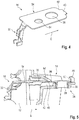
- the cable lug 16 (see FIG. 4 ) has a cable holding portion 32 which continues integrally into a mounting plate 34. The entire cable lug 16 is formed from a metal sheet.
- the formed in a known manner cable holding portion 32 serves to receive a cable end and electrically connected to the mounting plate 34.
- the cable (not shown) is here a ground cable and is part of the wiring harness which is accommodated in the housing 12 (not shown).
- the mounting plate 34 is substantially flat here, in the mounting plate 34 has a holding opening 36 is formed. In addition, the mounting plate 34 has a small projection 40 at its free end.
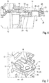
- FIG. 5 When the housing 12 is mounted around the harness, the ground wire is connected to the lug 16, and the lug 16 is inserted into the receptacle 14 on the housing 12 for pre-assembly.
- This situation (without cable and wiring harness) is in FIG. 5 shown.
- guide elements which facilitate an exact alignment of the mounting plate 34 in the receptacle 14.
- a plurality of support surfaces 42 for the mounting plate 34 and two lateral guide grooves 44 are formed on the housing 12.
- the insertion surfaces at the insertion end of the receptacle 14 are chamfered. These details are also in the FIGS. 7 to 9 shown.
- the positioning device comprises a plurality of separate elements, which may be implemented together or separately.
- a first element of the positioning device is formed by a stop 46 on a projection at the free end of the receptacle 14 in the housing 12 is formed. If the cable lug 16 is completely inserted into the receptacle 14, then an edge portion 48 of the mounting plate 34 adjoining the end projection 40 rests against the inwardly directed abutment surface 50 of the abutment 46. An inwardly directed extension on the stop 46 prevents axial lifting of the mounting plate 34 from the receptacle 14th
- the second element of the positioning device is here formed by a latching device which comprises two latching elements 52, 54 which engage in one another when the mounting plate 34 of the cable lug 16 has been correctly inserted into the receptacle 14.
- the first locking element 52 is formed by a protruding into the receptacle 14 detent spring on the housing 12.
- the second latching element 54 is realized by a latching opening in the mounting plate 34.
- the detent spring may either be integrally formed as a plastic part with the housing 12, or may be a separate, inserted into the housing 12 component.
- the detent spring engages with an audible noise in the detent opening 38 a.
- the latching opening is offset relative to the insertion direction E a piece relative to the holding opening 36, to allow a locking of the detent spring in the latching opening only in a unique mounting position of the cable lug 16.
- This correct preassembly corresponds to a fully inserted into the receptacle 14 position of the cable lug 16.
- the holding opening 36 of the lug 16 is above the mounting hole 28 of the receptacle 14 of the housing 12, so that the two openings 28, 36 overlap and in this example also exactly aligned.
- the detent spring holds the cable lug 16 in the preassembly position.
- FIGS. 6 and 9 show a variant in which the cable holding portion 32 of the cable lug 16 extends rectilinearly in extension of the mounting plate 34, and is not angled. Both versions are interchangeable.
- a cable lug 16 is used with an angled cable holding section 32, two apertures 58 in the housing 12 allow a simple fixation of the cable holding section 32 by means of a cable tie (not shown).
- the prefabricated assembly 10 with the housing 12 and the cable lug 16 preassembled thereon is positioned on the vehicle at the desired location and by means of the fastening bolt 18, which simultaneously passes through the fastening opening 28 of the housing 12 and the overlapping retaining opening 36 of the cable lug 16. firmly and definitively fixed to the vehicle.
Landscapes
- Details Of Connecting Devices For Male And Female Coupling (AREA)
- Installation Of Indoor Wiring (AREA)
Description
- Die Erfindung betrifft eine Baugruppe mit einem Gehäuse und einem Kabelschuh und ein System umfassend die Baugruppe und einen Befestigungsbolzen.
- Die
EP 1 133 022 A2 zeigt einen abgeschirmten Verbinder, mittels dem ein Anschlusskabel mit einem elektrischen Motor verbunden werden kann. Innerhalb eines Gehäuses sind zwei Kabelstücke elektrisch miteinander verbunden, die jeweils in einem Kabelschuh enden. Beide Kabelschuhe sind an einem Gehäuseteil befestigt, indem eine Schraube die Ösen beider Kabelschuhe gleichzeitig durchgreift. Das Gehäuse kann über Befestigungsöffnungen mittels weiterer Schraubverbindungen am Motor fixiert werden. - Die gattungsgemäße
JP 2010 272243 A - In der
US 5 897 392 A ist eine Baugruppe aus einem Stromverteilerkasten, einem daran ansteckbaren Stecker sowie einer Kabelabdeckung beschrieben, wobei die Kabelabdeckung und der Stecker über einen Befestigungsbolzen mit dem Verteilerkasten verschraubbar sind. - Bei der Montage eines Kabelbaums in einem Fahrzeug wird derzeit ein Kabelschacht, durch den Abschnitte des Kabelbaums verlaufen, beispielsweise am Motorblock fixiert, während die Erdung des Kabelbaums über eine separate Verbindung eines Erdungskabels mit einem elektrisch leitenden Bauteil, beispielsweise ebenfalls dem Motorgehäuse erfolgt.
- Aufgabe der Erfindung ist es, die Befestigung eines Gehäuses sowie beispielsweise eines damit verbundenen Erdungskabels zu vereinfachen.
- Hierzu wird erfindungsgemäß eine Baugruppe mit einem Gehäuse und mit einem Kabelschuh, mit den Merkmalen des Anspruchs 1, eingesetzt.
- Infolgedessen kann zur Fixierung des Gehäuses der Befestigungsbolzen gleichzeitig durch die Befestigungsöffnung des Gehäuses und durch die Halteöffnung des Kabelschuhs geschoben werden, und die Befestigung von Gehäuse und Erdungskabel kann in einem einzigen Arbeitsgang erfolgen.
- Außerdem ist eine Vormontage des Kabelschuhs im Gehäuse möglich. Das Vorsehen einer Positioniervorrichtung erlaubt es dabei, den Kabelschuh bei der Vormontage so in die Aufnahme einzulegen, dass bei der späteren Endmontage am Befestigungsbolzen die Positionierung des Kabelschuhs bezüglich der Befestigungsöffnung des Gehäuses erhalten bleibt. Der Kabelschuh liegt in der Aufnahme stets in einer Position, in der ein Überlappen der Halteöffnung mit der Befestigungsöffnung sichergestellt ist, sodass der Befestigungsbolzen gleichzeitig die Befestigungsöffnung des Gehäuses und die Halteöffnung des Kabelschuhs durchdringt.
- Das Gehäuse ist ein Kabelschachtgehäuse, das in einem Fahrzeug fixiert werden kann und das zur Aufnahme eines Teils eines Kabelbaums bestimmt ist.
- Das Kabelschachtgehäuse ist vorzugsweise an einem Motorgehäuse befestigt, das auch die Masse für die Erdung des gesamten Kabelbaums bildet. Die Befestigungsöffnung im Gehäuse ist beispielsweise in einer elektrisch leitfähigen Buchse ausgebildet, was das Herstellen einer elektrisch leitenden Verbindung zwischen dem Kabelschuh und dem Befestigungsbolzen vereinfacht.
- Der Befestigungsbolzen kann etwa ein Schraubbolzen am Fahrzeug oder eine separate Schraube sein, beispielsweise eine M6- oder M8-Schraube. Diese kann beispielsweise in einen Befestigungsdom eingreifen, der am Motorblock ausgebildet ist.
- Das restliche Gehäuse, abgesehen von der Befestigungsbuchse, besteht vorzugsweise aus einem geeigneten Kunststoff. Dabei sollte darauf geachtet werden, dass das Gehäuse inklusive der Aufnahme so ausgebildet ist, dass die Einzelteile des Gehäuses mit möglichst wenig Aufwand und bevorzugt ohne den Einsatz von Schiebern in Spritzgusswerkzeugen herstellbar sind.
- Das Gehäuse kann beispielsweise zweiteilig ausgebildet sein, was auch das Einlegen beispielsweise eines Kabelbaumabschnitts erleichtert.
- Die Befestigungsöffnung im Gehäuse kann beispielsweise an einem Gehäusevorsprung vorgesehen sein, wobei die Befestigungsöffnung parallel oder in einem Winkel zu einer Durchgangsöffnung des Gehäuses ausgerichtet sein kann. Die Durchgangsöffnung kann beispielsweise entlang der Erstreckungsrichtung des im Gehäuse aufgenommenen Kabelbaumabschnitts verlaufen.
- Wenn sich die Aufnahme für den Kabelschuh im Wesentlichen senkrecht zu der Durchlassöffnung des Gehäuses erstreckt, lässt sich die Halteöffnung des Kabelschuhs einfach überlappend mit der Befestigungsöffnung im Gehäuse ausrichten.
- Auf diese Weise ist eine Verschraubung des Gehäuses am Fahrzeug auch möglich, wenn der Kabelbaumabschnitt bereits im Gehäuse aufgenommen ist.
- Mit der erfindungsgemäßen Baugruppe ist es daher möglich, einen Kabelbaum so vorzufertigen, dass an einem Abschnitt bereits das Kabelschachtgehäuse vorgesehen ist, wobei ein Erdungskabel des Kabelbaums mit einem Kabelschuh versehen ist, der in einer Aufnahme des Gehäuses durch die Positioniervorrichtung in einer Endmontageposition gehalten wird. Ein so vorgefertigter Kabelbaum muss bei der Endmontage lediglich im Fahrzeug fixiert werden, indem der Befestigungsbolzen durch die überlappende Befestigungsöffnung und Halteöffnung von Gehäuse und Kabelschuh hindurchgreift.
- Die Positioniervorrichtung kann in einer möglichen Ausführungsform ein erstes Rastelement im Gehäuse umfassen, das in Eingriff mit einem zweiten Rastelement am Kabelschuh kommt, wenn dieser vollständig in die Aufnahme eingeschoben ist. Die so hergestellte Rastverbindung hält zum einen den Kabelschuh in seiner Endmontageposition und bietet zum anderen, beispielsweise durch ein hörbares Rastgeräusch, bei der Vormontage eine Kontrollmöglichkeit beim Einsetzen des Kabelschuhs in die Aufnahme.
- Das erste Rastelement ist beispielsweise eine Rastfeder und das zweite Rastelement eine Rastöffnung in einer Montageplatte des Kabelschuhs, in die die Rastfeder des Kabelschuhs eingreift. In diesem Fall ist vorzugsweise in der Montageplatte des Kabelschuhs auch die Halteöffnung ausgebildet. Halteöffnung und Rastöffnung können bezüglich der Einschubrichtung des Kabelschuhs in die Aufnahme hintereinander angeordnet sein, um eine schlanke Ausbildung des Kabelschuhs zu ermöglichen. Die Rastöffnung und die Halteöffnung können leicht gegeneinander versetzt sein, um eine Vormontage des Kabelschuhs nur in der korrekten Ausrichtung zuzulassen.
- Natürlich können auch anders ausgebildete Rastverbindungen zwischen Gehäuse und Kabelschuh verwendet werden. Alternativ oder zusätzlich kann die Positioniervorrichtung einen Anschlag am Gehäuse umfassen, der eine vollständig eingeschobene Position des Kabelschuhs definiert. Dieser Anschlag kann beispielsweise durch einen einstückig mit dem Gehäuse ausgebildeten Vorsprung realisiert sein.
- Der Kabelschuh kann geradlinig gestaltet sein, sodass das Kabel in Verlängerung der Montageplatte des Kabelschuhs absteht, oder kann ein abgewinkeltes Ende aufweisen. Im letzteren Fall sind vorzugsweise im Gehäuse zwei Durchbrüche vorgesehen, über die der Kabelschuh an seinem abgewinkelten Ende auf einfache Weise am Gehäuse fixierbar ist. Hierzu wird beispielsweise ein Ratschband oder Kabelbinder durch die beiden Durchbrüche gezogen und um das abgewinkelte Ende des Kabelschuhs fixiert. Die Durchbrüche lassen sich beispielsweise während des Spritzgussprozesses der Gehäuseteile mit formen.
- In der Aufnahme sind vorzugsweise Leitelemente für die Montageplatte des Kabelschuhs vorgesehen, beispielsweise in die Gehäuseteile eingeformte Nuten und/oder Rippen als Führungen und Auflageflächen. Diese Leitelemente verhindern ein ungewolltes Verdrehen und Verkippen des Kabelschuhs beim Einschieben in die Aufnahme. Am Einschubende der Aufnahme können Schrägen vorgesehen sein, die auch gleichzeitig als Entformhilfen für das Entformen der Gehäuseteile aus einer Spritzgussform dienen können.
- Die Erfindung wird nachfolgend anhand eines Ausführungsbeispiels mit Bezug auf die beigefügten Figuren näher beschrieben. In den Figuren zeigen:
-
Figur 1 eine erfindungsgemäße Baugruppe endmontiert an einem Fahrzeug; -
Figur 2 das Gehäuse der Baugruppe ausFigur 1 ; -
Figur 3 eine Detaildarstellung der Befestigungsöffnung des Gehäuses ausFigur 2 ; -
Figur 4 eine schematische perspektivische Darstellung des Kabelschuhs der erfindungsgemäßen Baugruppe; -
Figuren 5 und6 die erfindungsgemäße Baugruppe mit in die Gehäuseaufnahme eingeschobenem Kabelschuh für einen geraden und einen abgewinkelten Kabelschuh; -
Figur 7 einen Ausschnitt der erfindungsgemäßen Baugruppe mit einem vormontierten Kabelschuh; und -
Figuren 8 und 9 Details der erfindungsgemäßen Baugruppe mit in die Aufnahme eingeschobenem Kabelschuh. -
Figur 1 zeigt eine Baugruppe 10 mit einem Gehäuse 12, das eine Aufnahme 14 für einen Kabelschuh 16 aufweist. Der Kabelschuh 16 ist in der Aufnahme 14 vormontiert. Über einen Befestigungsbolzen 18, hier in Form einer Innensechskantschraube, sind das Gehäuse 12 und der Kabelschuh 16 gemeinsam an einem Fahrzeugteil 20 befestigt, das in diesem Beispiel durch einen Motorblock gebildet ist. - Das Gehäuse 12 ist näher in
Figur 2 dargestellt. Es besteht aus zwei zusammengesetzten Schalenteile 22, 24, die einen Hohlraum umschließen, der eine Durchgangsöffnung 25 bildet, die sich axial durch das gesamte Gehäuse 12 erstreckt. Die beiden Schalenteile 22, 24 des Gehäuses 12 sind hier miteinander über mehrere Rastverbindungen verbunden. Die Aufnahme 14 erstreckt sich hier im Wesentlichen senkrecht zur Durchgangsöffnung 25. - Das Gehäuse 12 ist im hier gezeigten Beispiel als Kabelschachtgehäuse ausgebildet und dient dazu, einen Abschnitt eines Kabelbaums eines Fahrzeugs aufzunehmen und diesen am Fahrzeug zu befestigen (nicht näher dargestellt). Hierzu ist an einem Schalenteil, hier dem Schalenteil 24, ein Vorsprung 26 ausgebildet, in dem die Aufnahme 14 für den Kabelschuh 16 ausgebildet ist. Im Bereich der Aufnahme 14 verläuft eine Befestigungsöffnung 28 durch den Vorsprung 26 hindurch, durch die der in
Figur 1 dargestellte Befestigungsbolzen 18 hindurchgreift, wenn das Gehäuse 12 am Fahrzeug montiert wird. Die Form des Gehäuses 12 kann natürlich auf den jeweiligen Einsatzzweck des Gehäuses 12 abgestimmt werden und ist nicht auf die hier gezeigte Form beschränkt. - Die beiden Schalenteile 22, 24 des Gehäuses 12 bestehen zumindest weitgehend aus Kunststoff und sind jeweils separat als Spritzgussteil gefertigt. Die Befestigungsöffnung 28 ist jedoch in einer metallischen, elektrisch leitfähigen, in den Vorsprung 26 eingesetzten Buchse 30 ausgebildet. Der Kabelschuh 16 (siehe
Figur 4 ) hat einen Kabelhalteabschnitt 32, der sich einstückig in eine Montageplatte 34 fortsetzt. Der gesamte Kabelschuh 16 ist aus einem Metallblech geformt. - Der auf bekannte Weise ausgebildete Kabelhalteabschnitt 32 dient dazu, ein Kabelende aufzunehmen und elektrisch leitend mit der Montageplatte 34 zu verbinden. Das (nicht gezeigte) Kabel ist hier ein Erdungskabel und ist Teil des Kabelbaums, der im Gehäuse 12 aufgenommen ist (nicht dargestellt).
- Die Montageplatte 34 ist hier im Wesentlichen eben ausgebildet, in der Montageplatte 34 ist eine Halteöffnung 36 ausgebildet. Außerdem weist die Montage- platte 34 an ihrem freien Ende einen kleinen Vorsprung 40 auf.
- Wenn das Gehäuse 12 um den Kabelbaum montiert wird, wird das Erdungskabel mit dem Kabelschuh 16 verbunden, und der Kabelschuh 16 wird zur Vormontage in die Aufnahme 14 am Gehäuse 12 eingeschoben. Diese Situation (ohne Kabel und Kabelbaum) ist in
Figur 5 dargestellt. Es sind Leitelemente vorgesehen, die eine exakte Ausrichtung der Montageplatte 34 in der Aufnahme 14 erleichtern. Beispielsweise sind am Gehäuse 12 mehrere Auflageflächen 42 für die Montageplatte 34 sowie zwei seitliche Führungsnuten 44 ausgebildet. Zum Erleichtern des Einführens des Kabelschuhs 16 sind die Einführflächen am Einschubende der Aufnahme 14 angeschrägt. Diese Details sind auch in denFiguren 7 bis 9 dargestellt. - Um die korrekte Vormontageposition der Montageplatte 34 des Kabelschuhs 16 in der Aufnahme 14 des Gehäuses 12 vor der Fixierung des Gehäuses 12 am Fahrzeug sicherzustellen und um den Kabelschuh 16 bis zu seiner Endmontage in dieser Position zu halten, ist eine Positioniervorrichtung vorgesehen. In diesem Beispiel weist die Positioniervorrichtung mehrere separate Elemente auf, die zusammen oder getrennt verwirklicht sein können.
- Ein erstes Element der Positioniervorrichtung ist durch einen Anschlag 46 gebildet, der an einem Vorsprung am freien Ende der Aufnahme 14 im Gehäuse 12 ausgebildet ist. Ist der Kabelschuh 16 vollständig in die Aufnahme 14 eingeschoben, so liegt ein an den endseitigen Vorsprung 40 anschließender Randabschnitt 48 der Montageplatte 34 an der nach innen gerichteten Anschlagsfläche 50 des Anschlags 46 an. Ein nach innen gerichteter Fortsatz am Anschlag 46 verhindert ein axiales Abheben der Montageplatte 34 aus der Aufnahme 14.
- Das zweite Element der Positioniervorrichtung ist hier durch eine Rastvorrichtung gebildet, die zwei Rastelemente 52, 54 umfasst, die ineinandergreifen, wenn die Montageplatte 34 des Kabelschuhs 16 korrekt in die Aufnahme 14 eingeschoben wurde.
- Das erste Rastelement 52 ist durch eine in die Aufnahme 14 ragende Rastfeder am Gehäuse 12 gebildet. Das das zweite Rastelement 54 ist durch eine Rastöffnung in der Montageplatte 34 realisiert. Die Rastfeder kann entweder einstückig als Kunststoffteil mit dem Gehäuse 12 ausgebildet sein, oder kann ein separates, in das Gehäuse 12 eingesetztes Bauteil sein.
- Beim Einschieben der Montageplatte 34 in Einschubrichtung E in die Aufnahme 14 rastet die Rastfeder mit einem hörbaren Geräusch in der Rastöffnung 38 ein.
- Die Rastöffnung ist bezüglich der Einschubrichtung E ein Stück gegenüber der Halteöffnung 36 versetzt, um ein Einrasten der Rastfeder in die Rastöffnung nur in einer eindeutigen Montagestellung des Kabelschuhs 16 zu erlauben.
- Wenn das freie Ende 56 der Rastfeder in die Rastöffnung eingreift, ergibt dies ein akustisches und haptisches Signal, das das Erreichen der korrekten Vormontageposition anzeigt, in der eine Endmontage möglich ist. Diese korrekte Vormontageposition entspricht einer vollständig in die Aufnahme 14 eingeschobenen Position des Kabelschuhs 16. In dieser korrekten Vormontageposition liegt die Halteöffnung 36 des Kabelschuhs 16 über der Befestigungsöffnung 28 der Aufnahme 14 des Gehäuses 12, sodass die beiden Öffnungen 28, 36 überlappen und in diesem Beispiel auch exakt fluchten. Die Rastfeder hält den Kabelschuh 16 auch in der Vormontageposition.
- Die
Figuren 6 und9 zeigen eine Variante, in der der Kabelhalteabschnitt 32 des Kabelschuhs 16 geradlinig in Verlängerung der Montageplatte 34 verläuft, und nicht abgewinkelt ist. Beide Varianten sind nach Belieben austauschbar. - Wird ein Kabelschuh 16 mit einem abgewinkelten Kabelhalteabschnitt 32 verwendet, so ermöglichen zwei Durchbrüche 58 im Gehäuse 12 eine einfache Fixierung des Kabelhalteabschnitts 32 mittels eines Kabelbinders (nicht dargestellt).
- Die so vorgefertigte Baugruppe 10 mit dem Gehäuse 12 und dem daran vormontierten Kabelschuh 16 wird am Fahrzeug an der gewünschten Stelle positioniert und mittels des Befestigungsbolzens 18, der gleichzeitig durch die Befestigungsöffnung 28 des Gehäuses 12 und die mit dieser überlappenden Halteöffnung 36 des Kabelschuhs 16 hindurchgreift, fest und endgültig am Fahrzeug fixiert.
Claims (9)
- Baugruppe (10) mit einem Gehäuse (12), das ein Kabelschachtgehäuse ist, das in einem Fahrzeug fixiert werden kann und das zur Aufnahme eines Teils eines Kabelbaums bestimmt ist, und einem Kabelschuh (16), der zur Verbindung mit einem Erdungskabel vorgesehen ist, mit einer Halteöffnung (36), wobei das Gehäuse (12) eine Befestigungsöffnung (28) aufweist, mit der das Gehäuse (12) zur Fixierung im Fahrzeug an einem Befestigungsbolzen (18) angebracht werden kann und eine Aufnahme (14) für den Kabelschuh (16), wobei die Aufnahme (14) eine Positioniervorrichtung für den Kabelschuh (16) aufweist und wobei der Kabelschuh (16) in der Aufnahme (14) so angeordnet ist, dass die Halteöffnung (36) mit der Befestigungsöffnung (28) überlappt, wobei zur Fixierung des Gehäuses (12) der Befestigungsbolzen (18) die Befestigungsöffnung (28) und die Halteöffnung (36) durchgreifen kann.
- Baugruppe nach einem der vorhergehenden Ansprüche, dadurch gekennzeichnet, dass das Gehäuse (12) an einem Motorgehäuse befestigt werden kann.
- Baugruppe nach einem der vorhergehenden Ansprüche, dadurch gekennzeichnet, dass die Befestigungsöffnung (28) im Gehäuse (12) in einer elektrisch leitfähigen Buchse (30) ausgebildet ist.
- Baugruppe nach einem der vorhergehenden Ansprüche, dadurch gekennzeichnet, dass sich die Aufnahme (14) für den Kabelschuh (16) im Wesentlichen senkrecht zu einer Durchgangsöffnung (25) des Gehäuses (12) erstreckt.
- Baugruppe nach einem der vorhergehenden Ansprüche, dadurch gekennzeichnet, dass die Positioniervorrichtung ein erstes Rastelement (52) im Gehäuse (12) umfasst, das in Eingriff mit einem zweiten Rastelement (54) am Kabelschuh (16) kommt, wenn dieser vollständig in die Aufnahme (14) eingeschoben ist.
- Baugruppe nach Anspruch 5, dadurch gekennzeichnet, dass das erste Rastelement (52) eine Rastfeder und das zweite Rastelement (54) eine Rastöffnung in einer Montageplatte (34) des Kabelschuhs (16) ist, in die die Rastfeder eingreift.
- Baugruppe nach einem der vorhergehenden Ansprüche, dadurch gekennzeichnet, dass die Positioniervorrichtung einen Anschlag (46) am Gehäuse (12) umfasst, der eine vollständig eingeschobene Position des Kabelschuhs (16) definiert.
- Baugruppe nach einem der vorhergehenden Ansprüche, dadurch gekennzeichnet, dass der Kabelschuh (16) einen abgewinkelten Kabelhalteabschnitt (32) aufweist und dass im Gehäuse (12) zwei Durchbrüche (58) vorgesehen sind, über die der Kabelschuh (16) an seinem abgewinkelten Kabelhalteabschnitt (32) am Gehäuse (12) fixierbar ist.
- System umfassend einen Befestigungsbolzen (18) und eine Baugruppe nach einem der vorgehenden Ansprüche, dadurch gekennzeichnet, dass der Befestigungsbolzen (18) einen Schraubbolzen am Fahrzeug oder eine Schraube ist.
Applications Claiming Priority (2)
| Application Number | Priority Date | Filing Date | Title |
|---|---|---|---|
| DE102015202785.6A DE102015202785A1 (de) | 2015-02-17 | 2015-02-17 | Baugruppe mit einem Gehäuse und einem Kabelschuh |
| PCT/EP2015/078018 WO2016131509A1 (de) | 2015-02-17 | 2015-11-30 | Baugruppe mit einem gehäuse und einem kabelschuh |
Publications (2)
| Publication Number | Publication Date |
|---|---|
| EP3259808A1 EP3259808A1 (de) | 2017-12-27 |
| EP3259808B1 true EP3259808B1 (de) | 2019-07-31 |
Family
ID=54705639
Family Applications (1)
| Application Number | Title | Priority Date | Filing Date |
|---|---|---|---|
| EP15801456.3A Active EP3259808B1 (de) | 2015-02-17 | 2015-11-30 | Baugruppe mit einem gehäuse und einem kabelschuh |
Country Status (3)
| Country | Link |
|---|---|
| EP (1) | EP3259808B1 (de) |
| DE (1) | DE102015202785A1 (de) |
| WO (1) | WO2016131509A1 (de) |
Families Citing this family (1)
| Publication number | Priority date | Publication date | Assignee | Title |
|---|---|---|---|---|
| DE102019216998A1 (de) * | 2019-11-05 | 2021-05-06 | Volkswagen Aktiengesellschaft | Verbindungsanordnung mit Rastscheibe |
Citations (1)
| Publication number | Priority date | Publication date | Assignee | Title |
|---|---|---|---|---|
| US5897392A (en) * | 1997-03-26 | 1999-04-27 | Yazaki Corporation | Wire retaining clip |
Family Cites Families (6)
| Publication number | Priority date | Publication date | Assignee | Title |
|---|---|---|---|---|
| FR2667989B1 (fr) * | 1990-10-16 | 1994-03-04 | Telemecanique Sa | Borne de connexion a vis imperdable et bornier utilisant des bornes de ce genre. |
| JP2605741Y2 (ja) * | 1992-07-23 | 2000-08-07 | 矢崎総業株式会社 | 接続端子の固定構造 |
| DE60133787T2 (de) * | 2000-03-07 | 2009-06-25 | AutoNetworks Technologies, Ltd., Nagoya | Abgeschirmter Verbinder und Anschlusskontaktanordnung für elektrisches abgeschirmtes Kabel |
| JP5251726B2 (ja) * | 2009-05-19 | 2013-07-31 | 住友電装株式会社 | コネクタ |
| JP5489763B2 (ja) * | 2010-02-03 | 2014-05-14 | 矢崎総業株式会社 | 充電コネクタの端子保持構造 |
| JP5413627B2 (ja) * | 2012-05-31 | 2014-02-12 | 株式会社葉山電器製作所 | 給電接続具 |
-
2015
- 2015-02-17 DE DE102015202785.6A patent/DE102015202785A1/de active Granted
- 2015-11-30 WO PCT/EP2015/078018 patent/WO2016131509A1/de not_active Ceased
- 2015-11-30 EP EP15801456.3A patent/EP3259808B1/de active Active
Patent Citations (1)
| Publication number | Priority date | Publication date | Assignee | Title |
|---|---|---|---|---|
| US5897392A (en) * | 1997-03-26 | 1999-04-27 | Yazaki Corporation | Wire retaining clip |
Also Published As
| Publication number | Publication date |
|---|---|
| DE102015202785A1 (de) | 2016-08-18 |
| WO2016131509A1 (de) | 2016-08-25 |
| EP3259808A1 (de) | 2017-12-27 |
Similar Documents
| Publication | Publication Date | Title |
|---|---|---|
| DE102010002176B4 (de) | Kontakteinrichtung | |
| DE69207217T2 (de) | Abgeschirmte elektrische Verbinderanordnung | |
| EP3613110B1 (de) | Baugruppe für ein steckverbinderteil mit einem kontakteinsatz und einem erdungselement | |
| EP2165580B1 (de) | Schliesssystem für fahrzeuge und verwendung eines komponententrägers | |
| EP2823536B1 (de) | Steckverbinder umfassend eine schutzleiterbrücke | |
| DE102018210892B4 (de) | Steckverbindungselement für ein Kraftfahrzeug und Verfahren zum Herstellen eines solchen Steckverbindungselements | |
| DE19809492A1 (de) | Elektrischer Verbinder | |
| DE102014205744B4 (de) | Steuergerät für ein Fahrzeugheizgerät | |
| DE20113304U1 (de) | Fahrzeuginnenraummodul | |
| DE60008347T2 (de) | Sicherungsdose | |
| EP3507861A1 (de) | Kraftfahrzeugtürgriffanordnung mit montageerleichterung | |
| DE102016007421B4 (de) | Trägervorrichtung, elektrische Baugruppe, Lenkrad, Fahrerairbagmodul und Verfahren zur Montage | |
| DE69933155T2 (de) | Drehschalter | |
| EP3221935B1 (de) | Elektrische verbindungsanordnung und verfahren zu deren herstellung | |
| EP1936757B1 (de) | Steckverbindersystem für eine Wandmontage | |
| DE102012105352A1 (de) | Positionierelement | |
| DE19614367C2 (de) | Montagevorrichtung für unterschiedliche Muttern | |
| EP3259808A1 (de) | Baugruppe mit einem gehäuse und einem kabelschuh | |
| DE102010064150B4 (de) | System zur lösbaren Anbringung eines elektrischen Verteilerkastens an einem Tragteil | |
| DE102009023292B4 (de) | Elektrischer Verbinder mit Kontaktbrücke und Verfahren zum Montieren der Kontaktbrücke | |
| DE102017212598A1 (de) | Stecker und Stecksystem mit einem Stecker | |
| EP1720222B1 (de) | Steckverbinder, insbesondere für Airbag-Zündsysteme | |
| DE10220615A1 (de) | Schildverbinder für eine Apparatur | |
| DE102012108859B4 (de) | Elektronikmodul | |
| DE102019200021A1 (de) | Kontaktierungsvorrichtung |
Legal Events
| Date | Code | Title | Description |
|---|---|---|---|
| STAA | Information on the status of an ep patent application or granted ep patent |
Free format text: STATUS: THE INTERNATIONAL PUBLICATION HAS BEEN MADE |
|
| PUAI | Public reference made under article 153(3) epc to a published international application that has entered the european phase |
Free format text: ORIGINAL CODE: 0009012 |
|
| STAA | Information on the status of an ep patent application or granted ep patent |
Free format text: STATUS: REQUEST FOR EXAMINATION WAS MADE |
|
| 17P | Request for examination filed |
Effective date: 20170706 |
|
| AK | Designated contracting states |
Kind code of ref document: A1 Designated state(s): AL AT BE BG CH CY CZ DE DK EE ES FI FR GB GR HR HU IE IS IT LI LT LU LV MC MK MT NL NO PL PT RO RS SE SI SK SM TR |
|
| AX | Request for extension of the european patent |
Extension state: BA ME |
|
| RIN1 | Information on inventor provided before grant (corrected) |
Inventor name: HALBEDL, KLAUS Inventor name: MAIER, CHRISTIAN Inventor name: STEINHOEGL, MANFRED Inventor name: GERSTORFER, JOHANN Inventor name: SKOWRON, MAREK |
|
| DAV | Request for validation of the european patent (deleted) | ||
| DAX | Request for extension of the european patent (deleted) | ||
| STAA | Information on the status of an ep patent application or granted ep patent |
Free format text: STATUS: EXAMINATION IS IN PROGRESS |
|
| 17Q | First examination report despatched |
Effective date: 20181120 |
|
| REG | Reference to a national code |
Ref country code: DE Ref legal event code: R079 Ref document number: 502015009836 Country of ref document: DE Free format text: PREVIOUS MAIN CLASS: H01R0013422000 Ipc: B60R0016020000 |
|
| GRAP | Despatch of communication of intention to grant a patent |
Free format text: ORIGINAL CODE: EPIDOSNIGR1 |
|
| STAA | Information on the status of an ep patent application or granted ep patent |
Free format text: STATUS: GRANT OF PATENT IS INTENDED |
|
| RIC1 | Information provided on ipc code assigned before grant |
Ipc: H01R 11/12 20060101ALI20190401BHEP Ipc: B60R 16/02 20060101AFI20190401BHEP Ipc: H01R 13/422 20060101ALI20190401BHEP |
|
| INTG | Intention to grant announced |
Effective date: 20190418 |
|
| GRAS | Grant fee paid |
Free format text: ORIGINAL CODE: EPIDOSNIGR3 |
|
| GRAA | (expected) grant |
Free format text: ORIGINAL CODE: 0009210 |
|
| STAA | Information on the status of an ep patent application or granted ep patent |
Free format text: STATUS: THE PATENT HAS BEEN GRANTED |
|
| AK | Designated contracting states |
Kind code of ref document: B1 Designated state(s): AL AT BE BG CH CY CZ DE DK EE ES FI FR GB GR HR HU IE IS IT LI LT LU LV MC MK MT NL NO PL PT RO RS SE SI SK SM TR |
|
| REG | Reference to a national code |
Ref country code: CH Ref legal event code: EP Ref country code: GB Ref legal event code: FG4D Free format text: NOT ENGLISH |
|
| REG | Reference to a national code |
Ref country code: AT Ref legal event code: REF Ref document number: 1160556 Country of ref document: AT Kind code of ref document: T Effective date: 20190815 |
|
| REG | Reference to a national code |
Ref country code: IE Ref legal event code: FG4D Free format text: LANGUAGE OF EP DOCUMENT: GERMAN |
|
| REG | Reference to a national code |
Ref country code: DE Ref legal event code: R096 Ref document number: 502015009836 Country of ref document: DE |
|
| REG | Reference to a national code |
Ref country code: NL Ref legal event code: MP Effective date: 20190731 |
|
| REG | Reference to a national code |
Ref country code: LT Ref legal event code: MG4D |
|
| PG25 | Lapsed in a contracting state [announced via postgrant information from national office to epo] |
Ref country code: PT Free format text: LAPSE BECAUSE OF FAILURE TO SUBMIT A TRANSLATION OF THE DESCRIPTION OR TO PAY THE FEE WITHIN THE PRESCRIBED TIME-LIMIT Effective date: 20191202 Ref country code: FI Free format text: LAPSE BECAUSE OF FAILURE TO SUBMIT A TRANSLATION OF THE DESCRIPTION OR TO PAY THE FEE WITHIN THE PRESCRIBED TIME-LIMIT Effective date: 20190731 Ref country code: SE Free format text: LAPSE BECAUSE OF FAILURE TO SUBMIT A TRANSLATION OF THE DESCRIPTION OR TO PAY THE FEE WITHIN THE PRESCRIBED TIME-LIMIT Effective date: 20190731 Ref country code: NL Free format text: LAPSE BECAUSE OF FAILURE TO SUBMIT A TRANSLATION OF THE DESCRIPTION OR TO PAY THE FEE WITHIN THE PRESCRIBED TIME-LIMIT Effective date: 20190731 Ref country code: BG Free format text: LAPSE BECAUSE OF FAILURE TO SUBMIT A TRANSLATION OF THE DESCRIPTION OR TO PAY THE FEE WITHIN THE PRESCRIBED TIME-LIMIT Effective date: 20191031 Ref country code: NO Free format text: LAPSE BECAUSE OF FAILURE TO SUBMIT A TRANSLATION OF THE DESCRIPTION OR TO PAY THE FEE WITHIN THE PRESCRIBED TIME-LIMIT Effective date: 20191031 Ref country code: HR Free format text: LAPSE BECAUSE OF FAILURE TO SUBMIT A TRANSLATION OF THE DESCRIPTION OR TO PAY THE FEE WITHIN THE PRESCRIBED TIME-LIMIT Effective date: 20190731 Ref country code: LT Free format text: LAPSE BECAUSE OF FAILURE TO SUBMIT A TRANSLATION OF THE DESCRIPTION OR TO PAY THE FEE WITHIN THE PRESCRIBED TIME-LIMIT Effective date: 20190731 |
|
| PG25 | Lapsed in a contracting state [announced via postgrant information from national office to epo] |
Ref country code: AL Free format text: LAPSE BECAUSE OF FAILURE TO SUBMIT A TRANSLATION OF THE DESCRIPTION OR TO PAY THE FEE WITHIN THE PRESCRIBED TIME-LIMIT Effective date: 20190731 Ref country code: GR Free format text: LAPSE BECAUSE OF FAILURE TO SUBMIT A TRANSLATION OF THE DESCRIPTION OR TO PAY THE FEE WITHIN THE PRESCRIBED TIME-LIMIT Effective date: 20191101 Ref country code: LV Free format text: LAPSE BECAUSE OF FAILURE TO SUBMIT A TRANSLATION OF THE DESCRIPTION OR TO PAY THE FEE WITHIN THE PRESCRIBED TIME-LIMIT Effective date: 20190731 Ref country code: RS Free format text: LAPSE BECAUSE OF FAILURE TO SUBMIT A TRANSLATION OF THE DESCRIPTION OR TO PAY THE FEE WITHIN THE PRESCRIBED TIME-LIMIT Effective date: 20190731 Ref country code: ES Free format text: LAPSE BECAUSE OF FAILURE TO SUBMIT A TRANSLATION OF THE DESCRIPTION OR TO PAY THE FEE WITHIN THE PRESCRIBED TIME-LIMIT Effective date: 20190731 |
|
| PG25 | Lapsed in a contracting state [announced via postgrant information from national office to epo] |
Ref country code: TR Free format text: LAPSE BECAUSE OF FAILURE TO SUBMIT A TRANSLATION OF THE DESCRIPTION OR TO PAY THE FEE WITHIN THE PRESCRIBED TIME-LIMIT Effective date: 20190731 |
|
| PG25 | Lapsed in a contracting state [announced via postgrant information from national office to epo] |
Ref country code: RO Free format text: LAPSE BECAUSE OF FAILURE TO SUBMIT A TRANSLATION OF THE DESCRIPTION OR TO PAY THE FEE WITHIN THE PRESCRIBED TIME-LIMIT Effective date: 20190731 Ref country code: PL Free format text: LAPSE BECAUSE OF FAILURE TO SUBMIT A TRANSLATION OF THE DESCRIPTION OR TO PAY THE FEE WITHIN THE PRESCRIBED TIME-LIMIT Effective date: 20190731 Ref country code: DK Free format text: LAPSE BECAUSE OF FAILURE TO SUBMIT A TRANSLATION OF THE DESCRIPTION OR TO PAY THE FEE WITHIN THE PRESCRIBED TIME-LIMIT Effective date: 20190731 Ref country code: EE Free format text: LAPSE BECAUSE OF FAILURE TO SUBMIT A TRANSLATION OF THE DESCRIPTION OR TO PAY THE FEE WITHIN THE PRESCRIBED TIME-LIMIT Effective date: 20190731 |
|
| PG25 | Lapsed in a contracting state [announced via postgrant information from national office to epo] |
Ref country code: CZ Free format text: LAPSE BECAUSE OF FAILURE TO SUBMIT A TRANSLATION OF THE DESCRIPTION OR TO PAY THE FEE WITHIN THE PRESCRIBED TIME-LIMIT Effective date: 20190731 Ref country code: SM Free format text: LAPSE BECAUSE OF FAILURE TO SUBMIT A TRANSLATION OF THE DESCRIPTION OR TO PAY THE FEE WITHIN THE PRESCRIBED TIME-LIMIT Effective date: 20190731 Ref country code: SK Free format text: LAPSE BECAUSE OF FAILURE TO SUBMIT A TRANSLATION OF THE DESCRIPTION OR TO PAY THE FEE WITHIN THE PRESCRIBED TIME-LIMIT Effective date: 20190731 Ref country code: IS Free format text: LAPSE BECAUSE OF FAILURE TO SUBMIT A TRANSLATION OF THE DESCRIPTION OR TO PAY THE FEE WITHIN THE PRESCRIBED TIME-LIMIT Effective date: 20200224 |
|
| REG | Reference to a national code |
Ref country code: DE Ref legal event code: R097 Ref document number: 502015009836 Country of ref document: DE |
|
| REG | Reference to a national code |
Ref country code: CH Ref legal event code: PL |
|
| PLBE | No opposition filed within time limit |
Free format text: ORIGINAL CODE: 0009261 |
|
| STAA | Information on the status of an ep patent application or granted ep patent |
Free format text: STATUS: NO OPPOSITION FILED WITHIN TIME LIMIT |
|
| PG2D | Information on lapse in contracting state deleted |
Ref country code: IS |
|
| PG25 | Lapsed in a contracting state [announced via postgrant information from national office to epo] |
Ref country code: MC Free format text: LAPSE BECAUSE OF FAILURE TO SUBMIT A TRANSLATION OF THE DESCRIPTION OR TO PAY THE FEE WITHIN THE PRESCRIBED TIME-LIMIT Effective date: 20190731 Ref country code: CH Free format text: LAPSE BECAUSE OF NON-PAYMENT OF DUE FEES Effective date: 20191130 Ref country code: LU Free format text: LAPSE BECAUSE OF NON-PAYMENT OF DUE FEES Effective date: 20191130 Ref country code: LI Free format text: LAPSE BECAUSE OF NON-PAYMENT OF DUE FEES Effective date: 20191130 Ref country code: IS Free format text: LAPSE BECAUSE OF FAILURE TO SUBMIT A TRANSLATION OF THE DESCRIPTION OR TO PAY THE FEE WITHIN THE PRESCRIBED TIME-LIMIT Effective date: 20191030 |
|
| 26N | No opposition filed |
Effective date: 20200603 |
|
| REG | Reference to a national code |
Ref country code: BE Ref legal event code: MM Effective date: 20191130 |
|
| PG25 | Lapsed in a contracting state [announced via postgrant information from national office to epo] |
Ref country code: SI Free format text: LAPSE BECAUSE OF FAILURE TO SUBMIT A TRANSLATION OF THE DESCRIPTION OR TO PAY THE FEE WITHIN THE PRESCRIBED TIME-LIMIT Effective date: 20190731 |
|
| PG25 | Lapsed in a contracting state [announced via postgrant information from national office to epo] |
Ref country code: IE Free format text: LAPSE BECAUSE OF NON-PAYMENT OF DUE FEES Effective date: 20191130 |
|
| PG25 | Lapsed in a contracting state [announced via postgrant information from national office to epo] |
Ref country code: BE Free format text: LAPSE BECAUSE OF NON-PAYMENT OF DUE FEES Effective date: 20191130 |
|
| PG25 | Lapsed in a contracting state [announced via postgrant information from national office to epo] |
Ref country code: CY Free format text: LAPSE BECAUSE OF FAILURE TO SUBMIT A TRANSLATION OF THE DESCRIPTION OR TO PAY THE FEE WITHIN THE PRESCRIBED TIME-LIMIT Effective date: 20190731 |
|
| PG25 | Lapsed in a contracting state [announced via postgrant information from national office to epo] |
Ref country code: MT Free format text: LAPSE BECAUSE OF FAILURE TO SUBMIT A TRANSLATION OF THE DESCRIPTION OR TO PAY THE FEE WITHIN THE PRESCRIBED TIME-LIMIT Effective date: 20190731 Ref country code: HU Free format text: LAPSE BECAUSE OF FAILURE TO SUBMIT A TRANSLATION OF THE DESCRIPTION OR TO PAY THE FEE WITHIN THE PRESCRIBED TIME-LIMIT; INVALID AB INITIO Effective date: 20151130 |
|
| REG | Reference to a national code |
Ref country code: AT Ref legal event code: MM01 Ref document number: 1160556 Country of ref document: AT Kind code of ref document: T Effective date: 20201130 |
|
| PG25 | Lapsed in a contracting state [announced via postgrant information from national office to epo] |
Ref country code: AT Free format text: LAPSE BECAUSE OF NON-PAYMENT OF DUE FEES Effective date: 20201130 |
|
| PG25 | Lapsed in a contracting state [announced via postgrant information from national office to epo] |
Ref country code: MK Free format text: LAPSE BECAUSE OF FAILURE TO SUBMIT A TRANSLATION OF THE DESCRIPTION OR TO PAY THE FEE WITHIN THE PRESCRIBED TIME-LIMIT Effective date: 20190731 |
|
| P01 | Opt-out of the competence of the unified patent court (upc) registered |
Effective date: 20230503 |
|
| PGFP | Annual fee paid to national office [announced via postgrant information from national office to epo] |
Ref country code: DE Payment date: 20251110 Year of fee payment: 11 |
|
| PGFP | Annual fee paid to national office [announced via postgrant information from national office to epo] |
Ref country code: GB Payment date: 20251120 Year of fee payment: 11 |
|
| PGFP | Annual fee paid to national office [announced via postgrant information from national office to epo] |
Ref country code: IT Payment date: 20251128 Year of fee payment: 11 |
|
| PGFP | Annual fee paid to national office [announced via postgrant information from national office to epo] |
Ref country code: FR Payment date: 20251120 Year of fee payment: 11 |