EP3258863B1 - Atherectomy apparatus with imaging - Google Patents
Atherectomy apparatus with imaging Download PDFInfo
- Publication number
- EP3258863B1 EP3258863B1 EP16702817.4A EP16702817A EP3258863B1 EP 3258863 B1 EP3258863 B1 EP 3258863B1 EP 16702817 A EP16702817 A EP 16702817A EP 3258863 B1 EP3258863 B1 EP 3258863B1
- Authority
- EP
- European Patent Office
- Prior art keywords
- catheter
- catheter body
- cutting
- cutter
- assembly
- Prior art date
- Legal status (The legal status is an assumption and is not a legal conclusion. Google has not performed a legal analysis and makes no representation as to the accuracy of the status listed.)
- Active
Links
- 238000003384 imaging method Methods 0.000 title claims description 90
- 238000005520 cutting process Methods 0.000 claims description 168
- 239000000463 material Substances 0.000 claims description 92
- 238000012014 optical coherence tomography Methods 0.000 claims description 26
- 238000002604 ultrasonography Methods 0.000 claims description 22
- 238000005259 measurement Methods 0.000 claims description 6
- 238000005452 bending Methods 0.000 description 56
- 210000001519 tissue Anatomy 0.000 description 33
- 210000001367 artery Anatomy 0.000 description 27
- 238000000034 method Methods 0.000 description 24
- 238000012545 processing Methods 0.000 description 22
- 230000003287 optical effect Effects 0.000 description 19
- 210000003127 knee Anatomy 0.000 description 16
- 239000000306 component Substances 0.000 description 15
- 238000002608 intravascular ultrasound Methods 0.000 description 15
- 229910052751 metal Inorganic materials 0.000 description 14
- 239000002184 metal Substances 0.000 description 14
- 208000007536 Thrombosis Diseases 0.000 description 13
- 230000000712 assembly Effects 0.000 description 13
- 238000000429 assembly Methods 0.000 description 13
- 210000002414 leg Anatomy 0.000 description 13
- 239000002245 particle Substances 0.000 description 12
- 210000004369 blood Anatomy 0.000 description 11
- 239000008280 blood Substances 0.000 description 11
- 210000003090 iliac artery Anatomy 0.000 description 11
- 210000004204 blood vessel Anatomy 0.000 description 10
- 201000001320 Atherosclerosis Diseases 0.000 description 9
- 239000012530 fluid Substances 0.000 description 9
- 239000000523 sample Substances 0.000 description 9
- 230000002093 peripheral effect Effects 0.000 description 8
- 230000002792 vascular Effects 0.000 description 8
- 208000037260 Atherosclerotic Plaque Diseases 0.000 description 7
- 230000015572 biosynthetic process Effects 0.000 description 7
- 238000012512 characterization method Methods 0.000 description 7
- 230000006870 function Effects 0.000 description 7
- 230000007246 mechanism Effects 0.000 description 7
- 238000001228 spectrum Methods 0.000 description 7
- 206010003210 Arteriosclerosis Diseases 0.000 description 6
- 210000003484 anatomy Anatomy 0.000 description 6
- HVYWMOMLDIMFJA-DPAQBDIFSA-N cholesterol Chemical compound C1C=C2C[C@@H](O)CC[C@]2(C)[C@@H]2[C@@H]1[C@@H]1CC[C@H]([C@H](C)CCCC(C)C)[C@@]1(C)CC2 HVYWMOMLDIMFJA-DPAQBDIFSA-N 0.000 description 6
- 230000006835 compression Effects 0.000 description 6
- 238000007906 compression Methods 0.000 description 6
- 210000005166 vasculature Anatomy 0.000 description 6
- 238000013459 approach Methods 0.000 description 5
- 230000004044 response Effects 0.000 description 5
- 238000010183 spectrum analysis Methods 0.000 description 5
- 238000012285 ultrasound imaging Methods 0.000 description 5
- 210000003462 vein Anatomy 0.000 description 5
- 239000002699 waste material Substances 0.000 description 5
- 239000010963 304 stainless steel Substances 0.000 description 4
- 229910000589 SAE 304 stainless steel Inorganic materials 0.000 description 4
- 208000027418 Wounds and injury Diseases 0.000 description 4
- 230000009471 action Effects 0.000 description 4
- 238000001514 detection method Methods 0.000 description 4
- 210000001105 femoral artery Anatomy 0.000 description 4
- 206010020718 hyperplasia Diseases 0.000 description 4
- 238000002156 mixing Methods 0.000 description 4
- 210000003137 popliteal artery Anatomy 0.000 description 4
- 210000002465 tibial artery Anatomy 0.000 description 4
- 238000012546 transfer Methods 0.000 description 4
- 238000003466 welding Methods 0.000 description 4
- 210000000702 aorta abdominal Anatomy 0.000 description 3
- 230000004323 axial length Effects 0.000 description 3
- 230000008901 benefit Effects 0.000 description 3
- 235000012000 cholesterol Nutrition 0.000 description 3
- 239000011248 coating agent Substances 0.000 description 3
- 238000000576 coating method Methods 0.000 description 3
- 230000003247 decreasing effect Effects 0.000 description 3
- 208000014674 injury Diseases 0.000 description 3
- 230000003447 ipsilateral effect Effects 0.000 description 3
- 238000003698 laser cutting Methods 0.000 description 3
- 239000007769 metal material Substances 0.000 description 3
- 230000003595 spectral effect Effects 0.000 description 3
- 230000008733 trauma Effects 0.000 description 3
- 238000012800 visualization Methods 0.000 description 3
- OYPRJOBELJOOCE-UHFFFAOYSA-N Calcium Chemical compound [Ca] OYPRJOBELJOOCE-UHFFFAOYSA-N 0.000 description 2
- 208000005189 Embolism Diseases 0.000 description 2
- HTTJABKRGRZYRN-UHFFFAOYSA-N Heparin Chemical compound OC1C(NC(=O)C)C(O)OC(COS(O)(=O)=O)C1OC1C(OS(O)(=O)=O)C(O)C(OC2C(C(OS(O)(=O)=O)C(OC3C(C(O)C(O)C(O3)C(O)=O)OS(O)(=O)=O)C(CO)O2)NS(O)(=O)=O)C(C(O)=O)O1 HTTJABKRGRZYRN-UHFFFAOYSA-N 0.000 description 2
- 239000000853 adhesive Substances 0.000 description 2
- 230000001070 adhesive effect Effects 0.000 description 2
- 238000002399 angioplasty Methods 0.000 description 2
- 230000000845 anti-microbial effect Effects 0.000 description 2
- 230000008321 arterial blood flow Effects 0.000 description 2
- QVGXLLKOCUKJST-UHFFFAOYSA-N atomic oxygen Chemical compound [O] QVGXLLKOCUKJST-UHFFFAOYSA-N 0.000 description 2
- 229910052791 calcium Inorganic materials 0.000 description 2
- 239000011575 calcium Substances 0.000 description 2
- 230000015556 catabolic process Effects 0.000 description 2
- 210000004351 coronary vessel Anatomy 0.000 description 2
- 230000001419 dependent effect Effects 0.000 description 2
- 238000004090 dissolution Methods 0.000 description 2
- 229940079593 drug Drugs 0.000 description 2
- 239000003814 drug Substances 0.000 description 2
- -1 e.g. Polymers 0.000 description 2
- 238000002592 echocardiography Methods 0.000 description 2
- 238000000227 grinding Methods 0.000 description 2
- 229960002897 heparin Drugs 0.000 description 2
- 229920000669 heparin Polymers 0.000 description 2
- 230000002209 hydrophobic effect Effects 0.000 description 2
- 230000002390 hyperplastic effect Effects 0.000 description 2
- 238000011065 in-situ storage Methods 0.000 description 2
- 230000003902 lesion Effects 0.000 description 2
- 238000003754 machining Methods 0.000 description 2
- 238000010338 mechanical breakdown Methods 0.000 description 2
- 229910052760 oxygen Inorganic materials 0.000 description 2
- 239000001301 oxygen Substances 0.000 description 2
- 239000004810 polytetrafluoroethylene Substances 0.000 description 2
- 229920001343 polytetrafluoroethylene Polymers 0.000 description 2
- 239000002002 slurry Substances 0.000 description 2
- 239000000126 substance Substances 0.000 description 2
- CCEKAJIANROZEO-UHFFFAOYSA-N sulfluramid Chemical group CCNS(=O)(=O)C(F)(F)C(F)(F)C(F)(F)C(F)(F)C(F)(F)C(F)(F)C(F)(F)C(F)(F)F CCEKAJIANROZEO-UHFFFAOYSA-N 0.000 description 2
- 238000001356 surgical procedure Methods 0.000 description 2
- 238000012935 Averaging Methods 0.000 description 1
- OKTJSMMVPCPJKN-UHFFFAOYSA-N Carbon Chemical compound [C] OKTJSMMVPCPJKN-UHFFFAOYSA-N 0.000 description 1
- 206010019280 Heart failures Diseases 0.000 description 1
- 206010021143 Hypoxia Diseases 0.000 description 1
- 206010028980 Neoplasm Diseases 0.000 description 1
- 208000031481 Pathologic Constriction Diseases 0.000 description 1
- 239000004696 Poly ether ether ketone Substances 0.000 description 1
- 229920002614 Polyether block amide Polymers 0.000 description 1
- 239000004698 Polyethylene Substances 0.000 description 1
- 239000004642 Polyimide Substances 0.000 description 1
- 208000010378 Pulmonary Embolism Diseases 0.000 description 1
- XUIMIQQOPSSXEZ-UHFFFAOYSA-N Silicon Chemical compound [Si] XUIMIQQOPSSXEZ-UHFFFAOYSA-N 0.000 description 1
- FAPWRFPIFSIZLT-UHFFFAOYSA-M Sodium chloride Chemical compound [Na+].[Cl-] FAPWRFPIFSIZLT-UHFFFAOYSA-M 0.000 description 1
- 244000273618 Sphenoclea zeylanica Species 0.000 description 1
- NRTOMJZYCJJWKI-UHFFFAOYSA-N Titanium nitride Chemical compound [Ti]#N NRTOMJZYCJJWKI-UHFFFAOYSA-N 0.000 description 1
- 210000001015 abdomen Anatomy 0.000 description 1
- 239000011358 absorbing material Substances 0.000 description 1
- 238000004458 analytical method Methods 0.000 description 1
- 229940127219 anticoagulant drug Drugs 0.000 description 1
- 230000009286 beneficial effect Effects 0.000 description 1
- JUPQTSLXMOCDHR-UHFFFAOYSA-N benzene-1,4-diol;bis(4-fluorophenyl)methanone Chemical compound OC1=CC=C(O)C=C1.C1=CC(F)=CC=C1C(=O)C1=CC=C(F)C=C1 JUPQTSLXMOCDHR-UHFFFAOYSA-N 0.000 description 1
- 239000012620 biological material Substances 0.000 description 1
- 230000005540 biological transmission Effects 0.000 description 1
- 230000017531 blood circulation Effects 0.000 description 1
- 239000012503 blood component Substances 0.000 description 1
- 230000036770 blood supply Effects 0.000 description 1
- 210000000988 bone and bone Anatomy 0.000 description 1
- 210000004556 brain Anatomy 0.000 description 1
- 210000004958 brain cell Anatomy 0.000 description 1
- 210000005013 brain tissue Anatomy 0.000 description 1
- 229910052799 carbon Inorganic materials 0.000 description 1
- 230000008859 change Effects 0.000 description 1
- 230000000295 complement effect Effects 0.000 description 1
- 238000002591 computed tomography Methods 0.000 description 1
- 239000000470 constituent Substances 0.000 description 1
- 239000002872 contrast media Substances 0.000 description 1
- 208000029078 coronary artery disease Diseases 0.000 description 1
- 230000008878 coupling Effects 0.000 description 1
- 238000010168 coupling process Methods 0.000 description 1
- 238000005859 coupling reaction Methods 0.000 description 1
- 230000006378 damage Effects 0.000 description 1
- 230000007547 defect Effects 0.000 description 1
- 238000002059 diagnostic imaging Methods 0.000 description 1
- 238000009826 distribution Methods 0.000 description 1
- 230000008030 elimination Effects 0.000 description 1
- 238000003379 elimination reaction Methods 0.000 description 1
- 230000010102 embolization Effects 0.000 description 1
- 210000003038 endothelium Anatomy 0.000 description 1
- 238000005516 engineering process Methods 0.000 description 1
- 238000001914 filtration Methods 0.000 description 1
- 239000004811 fluoropolymer Substances 0.000 description 1
- 229920002313 fluoropolymer Polymers 0.000 description 1
- 238000011010 flushing procedure Methods 0.000 description 1
- 230000004907 flux Effects 0.000 description 1
- 210000004013 groin Anatomy 0.000 description 1
- 230000036541 health Effects 0.000 description 1
- 230000007954 hypoxia Effects 0.000 description 1
- 238000005286 illumination Methods 0.000 description 1
- 238000010348 incorporation Methods 0.000 description 1
- 238000002347 injection Methods 0.000 description 1
- 239000007924 injection Substances 0.000 description 1
- 210000004072 lung Anatomy 0.000 description 1
- 230000001926 lymphatic effect Effects 0.000 description 1
- 230000007257 malfunction Effects 0.000 description 1
- 238000013507 mapping Methods 0.000 description 1
- 239000000203 mixture Substances 0.000 description 1
- 238000012986 modification Methods 0.000 description 1
- 230000004048 modification Effects 0.000 description 1
- 230000009826 neoplastic cell growth Effects 0.000 description 1
- 230000001613 neoplastic effect Effects 0.000 description 1
- 229910001000 nickel titanium Inorganic materials 0.000 description 1
- HLXZNVUGXRDIFK-UHFFFAOYSA-N nickel titanium Chemical compound [Ti].[Ti].[Ti].[Ti].[Ti].[Ti].[Ti].[Ti].[Ti].[Ti].[Ti].[Ni].[Ni].[Ni].[Ni].[Ni].[Ni].[Ni].[Ni].[Ni].[Ni].[Ni].[Ni].[Ni].[Ni] HLXZNVUGXRDIFK-UHFFFAOYSA-N 0.000 description 1
- 239000013307 optical fiber Substances 0.000 description 1
- 238000005457 optimization Methods 0.000 description 1
- 210000000056 organ Anatomy 0.000 description 1
- 238000004806 packaging method and process Methods 0.000 description 1
- 210000000277 pancreatic duct Anatomy 0.000 description 1
- 238000000059 patterning Methods 0.000 description 1
- 239000004033 plastic Substances 0.000 description 1
- 229920003023 plastic Polymers 0.000 description 1
- 229920000052 poly(p-xylylene) Polymers 0.000 description 1
- 229920002530 polyetherether ketone Polymers 0.000 description 1
- 229920000573 polyethylene Polymers 0.000 description 1
- 229920001721 polyimide Polymers 0.000 description 1
- 229920000642 polymer Polymers 0.000 description 1
- 229920002635 polyurethane Polymers 0.000 description 1
- 239000004814 polyurethane Substances 0.000 description 1
- 238000011176 pooling Methods 0.000 description 1
- 238000002203 pretreatment Methods 0.000 description 1
- 230000008569 process Effects 0.000 description 1
- 238000003672 processing method Methods 0.000 description 1
- 230000000750 progressive effect Effects 0.000 description 1
- 230000009467 reduction Effects 0.000 description 1
- 238000002310 reflectometry Methods 0.000 description 1
- 230000000241 respiratory effect Effects 0.000 description 1
- 208000037803 restenosis Diseases 0.000 description 1
- 231100000241 scar Toxicity 0.000 description 1
- 229910052710 silicon Inorganic materials 0.000 description 1
- 239000010703 silicon Substances 0.000 description 1
- 239000011780 sodium chloride Substances 0.000 description 1
- 229910001220 stainless steel Inorganic materials 0.000 description 1
- 239000010935 stainless steel Substances 0.000 description 1
- 230000036262 stenosis Effects 0.000 description 1
- 208000037804 stenosis Diseases 0.000 description 1
- 230000002966 stenotic effect Effects 0.000 description 1
- 238000003860 storage Methods 0.000 description 1
- 238000011477 surgical intervention Methods 0.000 description 1
- 238000010408 sweeping Methods 0.000 description 1
- 230000002194 synthesizing effect Effects 0.000 description 1
- 230000002123 temporal effect Effects 0.000 description 1
- 230000001732 thrombotic effect Effects 0.000 description 1
- 230000009772 tissue formation Effects 0.000 description 1
- 230000007704 transition Effects 0.000 description 1
- MTPVUVINMAGMJL-UHFFFAOYSA-N trimethyl(1,1,2,2,2-pentafluoroethyl)silane Chemical compound C[Si](C)(C)C(F)(F)C(F)(F)F MTPVUVINMAGMJL-UHFFFAOYSA-N 0.000 description 1
- 210000000689 upper leg Anatomy 0.000 description 1
- 210000000626 ureter Anatomy 0.000 description 1
- 230000000007 visual effect Effects 0.000 description 1
Images


Classifications
-
- A—HUMAN NECESSITIES
- A61—MEDICAL OR VETERINARY SCIENCE; HYGIENE
- A61B—DIAGNOSIS; SURGERY; IDENTIFICATION
- A61B17/00—Surgical instruments, devices or methods, e.g. tourniquets
- A61B17/32—Surgical cutting instruments
- A61B17/3205—Excision instruments
- A61B17/3207—Atherectomy devices working by cutting or abrading; Similar devices specially adapted for non-vascular obstructions
- A61B17/320758—Atherectomy devices working by cutting or abrading; Similar devices specially adapted for non-vascular obstructions with a rotating cutting instrument, e.g. motor driven
-
- A—HUMAN NECESSITIES
- A61—MEDICAL OR VETERINARY SCIENCE; HYGIENE
- A61B—DIAGNOSIS; SURGERY; IDENTIFICATION
- A61B8/00—Diagnosis using ultrasonic, sonic or infrasonic waves
- A61B8/12—Diagnosis using ultrasonic, sonic or infrasonic waves in body cavities or body tracts, e.g. by using catheters
-
- A—HUMAN NECESSITIES
- A61—MEDICAL OR VETERINARY SCIENCE; HYGIENE
- A61B—DIAGNOSIS; SURGERY; IDENTIFICATION
- A61B8/00—Diagnosis using ultrasonic, sonic or infrasonic waves
- A61B8/44—Constructional features of the ultrasonic, sonic or infrasonic diagnostic device
- A61B8/4483—Constructional features of the ultrasonic, sonic or infrasonic diagnostic device characterised by features of the ultrasound transducer
- A61B8/4488—Constructional features of the ultrasonic, sonic or infrasonic diagnostic device characterised by features of the ultrasound transducer the transducer being a phased array
-
- A—HUMAN NECESSITIES
- A61—MEDICAL OR VETERINARY SCIENCE; HYGIENE
- A61B—DIAGNOSIS; SURGERY; IDENTIFICATION
- A61B17/00—Surgical instruments, devices or methods, e.g. tourniquets
- A61B2017/00681—Aspects not otherwise provided for
- A61B2017/00685—Archimedes screw
-
- A—HUMAN NECESSITIES
- A61—MEDICAL OR VETERINARY SCIENCE; HYGIENE
- A61B—DIAGNOSIS; SURGERY; IDENTIFICATION
- A61B17/00—Surgical instruments, devices or methods, e.g. tourniquets
- A61B17/22—Implements for squeezing-off ulcers or the like on the inside of inner organs of the body; Implements for scraping-out cavities of body organs, e.g. bones; Calculus removers; Calculus smashing apparatus; Apparatus for removing obstructions in blood vessels, not otherwise provided for
- A61B2017/22038—Implements for squeezing-off ulcers or the like on the inside of inner organs of the body; Implements for scraping-out cavities of body organs, e.g. bones; Calculus removers; Calculus smashing apparatus; Apparatus for removing obstructions in blood vessels, not otherwise provided for with a guide wire
- A61B2017/22042—Details of the tip of the guide wire
-
- A—HUMAN NECESSITIES
- A61—MEDICAL OR VETERINARY SCIENCE; HYGIENE
- A61B—DIAGNOSIS; SURGERY; IDENTIFICATION
- A61B90/00—Instruments, implements or accessories specially adapted for surgery or diagnosis and not covered by any of the groups A61B1/00 - A61B50/00, e.g. for luxation treatment or for protecting wound edges
- A61B90/06—Measuring instruments not otherwise provided for
- A61B2090/064—Measuring instruments not otherwise provided for for measuring force, pressure or mechanical tension
-
- A—HUMAN NECESSITIES
- A61—MEDICAL OR VETERINARY SCIENCE; HYGIENE
- A61B—DIAGNOSIS; SURGERY; IDENTIFICATION
- A61B90/00—Instruments, implements or accessories specially adapted for surgery or diagnosis and not covered by any of the groups A61B1/00 - A61B50/00, e.g. for luxation treatment or for protecting wound edges
- A61B90/36—Image-producing devices or illumination devices not otherwise provided for
- A61B90/37—Surgical systems with images on a monitor during operation
- A61B2090/373—Surgical systems with images on a monitor during operation using light, e.g. by using optical scanners
- A61B2090/3735—Optical coherence tomography [OCT]
-
- A—HUMAN NECESSITIES
- A61—MEDICAL OR VETERINARY SCIENCE; HYGIENE
- A61B—DIAGNOSIS; SURGERY; IDENTIFICATION
- A61B90/00—Instruments, implements or accessories specially adapted for surgery or diagnosis and not covered by any of the groups A61B1/00 - A61B50/00, e.g. for luxation treatment or for protecting wound edges
- A61B90/36—Image-producing devices or illumination devices not otherwise provided for
- A61B90/37—Surgical systems with images on a monitor during operation
- A61B2090/378—Surgical systems with images on a monitor during operation using ultrasound
- A61B2090/3782—Surgical systems with images on a monitor during operation using ultrasound transmitter or receiver in catheter or minimal invasive instrument
- A61B2090/3784—Surgical systems with images on a monitor during operation using ultrasound transmitter or receiver in catheter or minimal invasive instrument both receiver and transmitter being in the instrument or receiver being also transmitter
Definitions
- Atherosclerosis is due to the build of atheroma material along the arterial walls.
- Atheroma deposits can have widely varying properties, with some deposits being relatively soft and others being fibrous and/or calcified. In the latter case, the deposits are frequently referred to as plaque.
- thrombosis and atherosclerosis are both present in the veins. For example, a thrombus develops around the atherosclerotic plaque.
- Strokes occur when the blood clot or plaque blocks an artery supplying blood to the brain, thus depriving brain tissue of oxygen. Without oxygen, brain cells begin to die.
- Embolisms occur when a blood clot travels around the body and lodges itself in an organ. For example, a pulmonary embolism is a blockage of the blood supply to the lungs that causes severe hypoxia and cardiac failure.
- the imaging assembly of the apparatus advantageously provides intraluminal guidance during treatment.
- the imaging assembly may be a forward-viewing imaging element, a side- viewing imaging element, or a combination thereof.
- Suitable imaging assemblies include ultrasound imaging assemblies and optical coherence tomography imaging assemblies.
- apparatuses of the invention include one cutting element, although some embodiments include more than one cutting element.
- the cutting element may include one or more flutes that form a cutting blade.
- the flutes typically have a positive rake angle.
- the positive rake angle may be at least 20 degrees. In some variations, the positive rake angle may range from 40 to 80 degrees.
- the cutting element may also include one or more crushing elements.
- the crushing elements may have a negative rake angle and are substantially rectangular in shape.
- the negative rake angle may range from at least 1, 5, 10, 15, 20, 25, 30 degrees or more. Where the cutting element is designed to slice/cut through the blockage, the crushing element is configured to provide blunt force to the blockage. It is contemplated that other positive and negative rake angles may be use for the cutting element and the crushing element.
- Apparatuses of the invention include a conveying element associated with the rotatable shaft.
- the conveying element acts to remove the broken down particles from the vessel, thereby minimizing the amount of particles that are undesirably released into the blood stream.
- the present invention provides atherectomy devices for removing occlusions within blood vessel while allowing real-time imaging of the procedure.
- the devices of the present invention are designed to break down and remove blood clots, such as such as emboli and thrombi, atheroma, plaque and other occlusive material from body lumens.
- the body lumens generally are diseased body lumens and in particular coronary arteries.
- the defect in the body lumen can be a de novo clot or an in-stent clot for example.
- the devices and exemplary methods are also suitable for treating stenosis of body lumens and other hyperplastic and neoplastic conditions in other body lumens, such as the ureter, the biliary duct, respiratory passages, the pancreatic duct, the lymphatic duct, and the like.
- Neoplastic cell growth will often occur as a result of a tumor surrounding and intruding into a body lumen. Removal of such material can thus be beneficial to maintain patency of the body lumen.
- the devices of the present invention can collect lumenectomy samples or materials. While the remaining discussion is directed at aspirating, imaging, and passing through atheromatous or thrombotic occlusive material in a coronary artery, it will be appreciated that the systems and devices of the present invention can be used to aspirate and/or pass through a variety of occlusive, stenotic, or hyperplastic material in a variety of body lumens.
- Atherectomy devices of the invention are particularly well-suited for the treatment of atherosclerosis.
- Atherosclerosis commonly affects the medium and large arteries, and may occur when fat, cholesterol, and other substances build up on the walls of arteries and form fleshy or hard/calcified structures called plaques/lesions.
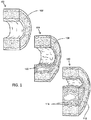
- FIG. 1 shows an instance of a first normal arterial segment (100) having a native arterial wall (102), a second arterial segment (104) with mild atherosclerosis and initial plaque (106) formation on the native arterial wall (108), and a third arterial segment (110) with severe atherosclerosis and having advanced plaque (112) formation on the native arterial wall (114).
- the artery may narrow and become less flexible, which may make it more difficult for blood to flow therethrough.
- the plaque is typically not localized, but can extend in length along the axis of the artery for as much as 10 mm or more (in some instance up to 400 mm or more).
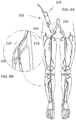
- FIG. 2 shows the anatomy of major arteries of a leg (200) (the right leg is shown for the purpose of illustration).
- the abdominal aorta (202) is the largest artery in the body, and its diameter can range from 19 to 25 mm (about 0.75 to about 1 inch).
- the abdominal aorta successively branches or divides numerous times between the proximal and distal regions of the legs. Each successive branch or division may reduce the diameter of the arteries in the direction of arterial blood flow from the heart to the feet, and the tortuousity of the path generally increases.
- the first branching is at the groin, into the left (204) and right (206) common iliac arteries.
- the left common iliac artery (204) branches into the internal (208) and external (209) iliac arteries.
- the external iliac artery (209) becomes the common femoral artery (210) or "CPA”.
- the CPA further connects to the superficial femoral artery (212) or "SPA”.
- the SPA connects to the popliteal artery (214), which runs behind the flexible region of the knee.
- the SFA generally has a diameter of about 5 to 7 mm, or about 0.2 to 0.25 inch.
- Atherectomy devices are usually introduced into the vasculature though an iliac artery by either an ipsilateral (i.e., same side) or a contralateral (i.e., opposite side) approach, and typically advanced under fluoroscopic radiographic image guidance through the CFA and into the SFA.
- ipsilateral i.e., same side
- contralateral i.e., opposite side
- FIGS. 3A and 3B illustrate an atherectomy system according to certain embodiments.
- the atherectomy system (300) may include an intravascular atherectomy apparatus (302) and a guide wire (304) over which the atherectomy apparatus (302) maybe deployed.
- the guide wire (304) is preferably silicon-coated or non-coated (bare), or otherwise free of a PTFE coating.
- the atherectomy systems described here may comprise a guide wire that includes a PTFE coating, or that does not include a guide wire at all.
- the guidewire may be a sensing guidewire.
- the guidewire may be configured to measure functional parameters, such as flow, pressure, temperature, etc.
- Exemplary functional measurement devices suitable for use in practicing the invention include FloWire Doppler Guidewire and the ComboWire XT Guidewire by Volcano Corporation.
- the atherectomy apparatus (302) generally includes an elongated catheter body (306) having a central axis.
- the catheter body (306) may be sized and configured to be advanced over the guide wire (304) in a blood vessel from an external percutaneous access site.
- the access approach can be ipsilateral or contralateral, and down to the targeted region.
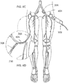
- FIGS. 4A and 4B depict views of the anatomy of a patient with a distal portion of the atherectomy apparatus (302) advanced using an ipsilateral approach to a target region in the anterior tibial artery (220).
- the atherectomy apparatus (302) may be introduced into an access site (400) in the right iliac artery (400).
- the atherectomy apparatus (302) may also include a handle (308) is coupled to the proximal (i.e., closest to the caregiver) end of the catheter body (306).
- the handle may be sized and configured to be securely held and manipulated by a caregiver outside an intravascular path.
- the handle may be manipulated from outside the intravascular path near the percutaneous access site, which may allow a caregiver to advance the catheter body through the intravascular path, which, in the leg, generally becomes more tortuous as one proceeds toward the distal regions of the legs (below the knee and toward the feet).
- Image guidance e.g., CT, radiographic, in situ visualization carried on board the atherectomy apparatus or otherwise provided, or another suitable guidance modality, or combinations thereof
- the catheter body (306) may be advanced to provide access to a targeted region where fat, cholesterol, and other substances have accumulated on the walls of arteries to form plaques or lesions, which will also in general be referred to as 11 occlusive materials.
- the ultrasound imaging assembly may be a phased-array assembly, which includes a plurality of transducer elements.
- the imaging assembly (311) may located/embedded on a portion of the housing (314). In certain embodiments, the imaging assembly (311) circumscribes the housing (314). In other embodiments, the imaging assembly (311) is located on the catheter body (306) proximal to the housing (314). Imaging assemblies, such as imaging assembly (311), are described in more detail hereinafter.
- FIGS. 5A and 5B show a breakdown of an atherectomy apparatus (500) suitable for use with the atherectomy systems described here.
- atherectomy apparatus (500) may comprise a handle (502), a catheter body (504), and a cutter assembly (506), such as described above with respect to FIGS. 3A and 3B .
- the cutter assembly (506) may comprise a ferrule (508), a cutter housing (510), and a cutter including a first cutting element (512) and a second cutting element (514).
- the atherectomy apparatus (500) may comprise any suitable cutter assembly, such as those described in more detail below.
- the housing 510 includes an imaging assembly 511.
- the atherectomy apparatus (500) may include a motor (516), which in the embodiment shown in FIGS. 5A and 5B , may be contained within a housing portion (518) of the handle (502).
- the motor is desirably battery operated, either by use of replaceable batteries, by use of rechargeable batteries, or combinations thereof.
- a motor controller may desirably provide a consistent supply of power through all operating conditions, including no load through excessive torque and stall conditions.
- a control switch (520) e.g., slide switch, pushbutton, and/or potentiometer
- the motor may run at about 12,000 RPM at 6 volts nominal. The operating parameters can be changed by adjusting the gear ratio.
- a torque shaft (522) may connect the motor (502) to the cutter.
- the motor (502) may rotate the torque shaft (522), which may in turn rotate the cutter within the cutter housing (510) around the central axis of the catheter body.
- Rotation of the cutter of the cutter assembly (506) may cause the first (512) and/or second (514) cutting elements to cut occlusive material and convey the occlusive materials into the cutter housing (510) (a process also known as "debulking").
- the cutter assembly (506) captures the cut occlusive materials from the blood without the use of any vacuum aspiration (although it should be appreciated that in some variations, vacuum aspiration may assist conveyance of the cut occlusive material).
- Rotation of these components may serve several purposes.
- the rotation can act as a means to further dissolve the blockage.
- the rotation can assist in moving the broken down blockage particles into the catheter body (504) for removal.
- the rotation can serve to assist in imaging the luminal surfaces of the vessel wall (e.g. the luminal surfaces within intramural space).
- imaging elements such as optical coherence tomography and ultrasound imaging elements
- rotation of the catheter body (504) and associated elements counters the rotation of the torque shaft (522). This counter rotation may increase effectiveness of the internal conveyer (524) in removing the broken down particles.
- FIGS. 3A, 3B , 5A and 5B The individual components of the systems shown in FIGS. 3A, 3B , 5A and 5B are discussed in more detail hereinafter.
- the outer diameter of any section of the catheter body, including the cutter assembly it carries, may be dictated at least partially by the anatomy of the intravascular path and the intended target region. Specifically, it may be desirable to maximize the cutting effectiveness of the cutter assembly by maximizing the diameter of the cutter, while minimizing the potential of puncture or trauma to the vessel. Additionally, the outer diameter of the catheter body/cutter assembly may also be dictated at least partially by the diameter of a guide sheath or introducer selected that may be placed at an access site to allow introduction of the atherectomy apparatus into the vasculature. It maybe desirable to select a guide sheath or introducer sized to minimize pain, trauma, and blood loss during use, and to facilitate rapid closure of the access incision after removal, to thereby reduce the incidence of interventional complications.
- diameters of the peripheral arteries of the leg vary typically from relatively small in regions below the knee (2.0 mm) to relatively large in regions above the knee (7.0 mm).
- clinicians typically use guide sheaths sized from 5F (diagnostic) to 7F (interventional).
- the outer diameter of the catheter body for introduction through such a guide sheath may be selected to be approximately equal to or less than about 1.8 mm.
- This may lessen the force required to advance the catheter body through the vasculature and occlusive material, and may help prevent the catheter body from dragging against or sticking to tissue structures in the vessel, or otherwise impeding the progress of the cutter assembly through the occlusive materials.
- the reduced diameter of the catheter body may also permit the injection of radiographic contrast material around the catheter body in the guide sheath.
- an atherectomy apparatus for introduction through a 7F introducer system may have a 2.4 mm diameter cutter assembly and a catheter body having a 2.2 mm diameter.
- an atherectomy apparatus for introduction through a 5F or 6F introducer system may have a 1.8 mm diameter cutter assembly and a catheter body having a 1.6 mm diameter, or a 2.2 mm diameter cutter assembly and a catheter body having a 1.6 mm diameter.
- the catheter body may also desirably possess certain physical and mechanical properties, such as those described immediately below, which may enhance the function of the catheter body to support and guide passage of the cutter assembly through the intravascular path and the occlusive materials.
- column stiffness is the capability of the catheter body to withstand an axial load or compression while resisting bending.
- Column stiffness can be measured and characterized in conventional ways, and may be referred to as "pushability" herein.
- a higher column stiffness is desirable, and may allow the catheter body to transmit a higher axial force (compression) applied at the handle to the cutter assembly without buckling.
- tensile stiffness is the capability of the catheter body of withstanding tension while being stretched or pulled before the cross section starts to significantly contract (called “necking").
- Tensile stiffness can be measured and characterized in conventional ways, and may be referred to as "pullability" herein.
- a high tensile stiffness may be desirable, and may allow the catheter body to be pulled proximally along an intravascular path (e.g., to withdraw the cutter assembly) without necking.
- 1 inch 25.4 mm.
- 1 lbf 4.45 N.
- a tensile stiffness of 0.050 inches/lbf or greater may be desirable for the catheter bodies described here.
- Another potentially desirable property for the catheter body comprises torsional stiffness.
- torsional stiffness is the capability of the catheter body to transmit a rotational load (torque) without untwisting, over-twisting and/or deforming. Torsional stiffness may be measured and characterized in conventional ways, and may be referred to as "torquability" herein. The torsional stiffness may control the capability of the catheter body to transmit a given amount of rotation applied at its proximal end (i.e., the handle) to achieve a comparable amount of rotation at its distal end (i.e., the cutter assembly).
- a higher torsional stiffness may be desirable, to better allow for rotational transmission along the atherectomy apparatus (i.e., around a guide wire), without twisting or deforming.
- a torsional stiffness that achieves a 1:1 relationship between rotation applied at the proximal end and the rotation observed at the distal end may be desirable for the catheter bodies described here.
- Another potentially desirable property for the catheter body comprises bending stiffness.
- bending stiffness is the ability of the catheter shaft to bend in response to an applied bending force, without breaking or deforming (i.e., without taking a set). Bending stiffness is an extensive material property that can be measured and characterized in conventional ways, and may be referred to as "trackability" herein.
- a lower bending stiffness may be desirable to allow the catheter body to be navigated over a guide wire around sharp bends in the vasculature.
- a targeted bending stiffness of 0.5 inches (bend radius) or greater at mid-length of the catheter body may be desirable for the catheter bodies described here. If the catheter body includes an active deflection component at its distal end (as will be described in greater detail later), a targeted bending stiffness of 1.0" (bend radius) at the deflectable distal end may be desirable for the catheter bodies described here.
- a prescribed minimum bend radius also makes it possible to coil the catheter body for packaging without taking a set.
- trackability is thought to be inversely related to pushability/pullability and torquability. That is, greater pushability, pullability, and/or torquability in a catheter body may reduce the trackability of the catheter body.
- the catheter bodies described here may balance the pushability, pullability, torquability, and trackability for a given catheter body. The result may be a catheter body that is trackable, yet also possesses the requisite column strength, tensile strength, and torsional stiffness to be sufficiently pushable, pullable and torquable to allow navigation and advancement of a cutter assembly.
- the overall trackability of a given catheter body (in terms of its ability to reliably navigate over a guide wire) may be influenced mainly by the physical and mechanical characteristics of the catheter body at its distal end.
- the pushability, pullability, and torquability may be influenced mainly by the physical and mechanical characteristics of the catheter body proximal to its distal end. That is, the overall configuration of different regions of a catheter body may impart characteristics to the overall length of the catheter body, which may allow for optimization of the overall pushability, pullability, torquability, and trackability of the catheter body.
- the bending stiffness of the metal tube may be incrementally modulated along the length of the catheter body by creating zones of cut patterns along at least a portion of the length of the catheter body.
- the cut patterns may be formed in any suitable manner (e.g., via laser cutting), and the zones may impart a desired profile of bending stiffness over the length of the catheter body.
- cut pattern zones may be used to incrementally decrease the bending stiffness in a stepwise fashion from proximal end to distal end, to provide a minimum bending stiffness conducive to trackability at the distal end (where trackability is more desirable).
- the stepwise fashion in which the bending stiffness is decreased may be configured in a manner to help maintain the overall pushability, pullability, and torquability.
- one or more zones of the catheter body include helical cut patterns, threaded cut patterns, spiral cut patterns, or brickwork cut patterns.
- Selective rotation of the cutter assembly can thus be finely controlled by a combination of control knob manipulation and handle twisting.
- the housing may or may not be dynamic (i.e., able to rotate relative to the catheter body).
- the housing may be configured to rotate at the same speed or at a different speed than the cutter elements.
- the cutter housing may be dynamically driven to rotate in the same direction or in a counter direction relative to the cutter.
- the housing may include one or more imaging assemblies.
- the imaging assembly maybe located on or embedded within the housing.
- the imaging assembly may cover a portion of the housing, and preferably the imaging assembly circumscribes the housing.
- the imaging assembly is connected to one or more signal wires that run the length of the atherectomy device.
- a rounded distal edge may also tend to glance off tissue without grabbing or catching on the tissue, which may minimize the resistance felt by the atherectomy apparatus during advancement.
- the cutter housing may have a sharp or beveled distal edge.
- the cutter housing may have an inner bevel.
- the cutter housing may have an outer bevel.
- the outside diameter of the cutter may be less than the inside diameter of the cutter housing to create a desired cutting gap between the two. A larger gap may produce a larger cutting volume, but too large of a gap may permit tissue to enter the cutter housing while bypassing the cutter. Representative dimensions will be described in more detail later.
- the outside diameter of a portion of the cutter may be greater than or equal to the diameter of the cutter housing.
- the cutter may cut a larger diameter of tissue, which may reduce the likelihood that the cutter housing rubs against tissue during advancement while cutting, thereby facilitating advancement of the device.
- the cutter is coupled and rotatable by the torque shaft.
- the torque shaft may be, in turn, driven by the motor in the handle.
- the torque shaft may be fabricated from any suitable material, preferably one or more materials that may be consistent with the pushability, pullability, torquability, and trackability of the catheter body, as described above.
- the torque shaft may comprise a metal braid and/or one or more metal coils, and one or more portions of the torque shaft embedded in a polymer, e.g., PEBAX, polyurethane, polyethylene, fluoropolymers, parylene, polyimide, PEEK, and/or PET.
- the torque shaft may be made from a rigid material such as plastic, rendered flexible by incorporation of a spiral relief or groove.
- the torque shaft may comprises a flexible wire coil wound about a central lumen.
- the central lumen may be sized to accommodate the passage of a guide wire therethrough.
- the flexible wire coil may preferably be wound in the same direction as the intended direction of rotation of the torque shaft, which may cause the coil to open up if torsional resistance to rotation is encountered (as opposed to clamping down, which may cause the torque shaft to lock on to a guide wire positioned in the central lumen).
- the cutter of a cutter assembly may comprise multiple cutting elements.
- the cutter assembly (506) may comprise a cutter having first (512) and second (514) cutting elements.
- the first cutting element (512) may be positioned distally of second cutting element (514).
- the first cutting element (512) may comprise one or more cutting edges (528) which may at least partially project beyond the distal end of the cutter housing (510).
- at least a portion of the first cutting element (512) may have a diameter greater than or equal to the diameter of the cutter housing (510).
- the second cutting element (514) may be at least partially housed within the cutter housing (510), and may comprise one or more cutting edges (530). As shown in FIG. 5B , the cutting edges (530) of the second cutting element (514) may be entirely enclosed within the cutter housing (510). Generally, the first (512) and second (514) cutting elements may be physically coupled together (e.g., by adhesives or welding) for rotation in unison.
- the torque shaft may couple to a journal (532) in the second cutting element.
- the torque shaft may rotate both the first cutting element and second cutting element in unison.
- a proximal flange (534) on the second cutting element (514) maybe seated within a relieved proximal groove (536) in the cutter housing (510).
- the relieved proximal groove (536) may serve as an axial retainer for the first (512) and second (514) cutting elements within the cutter housing.
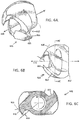
- the first cutting element (800) may comprise any suitable number of helical flutes (802) (e.g., one, two, three, four, or more helical flutes). Each cutting flute may form a cutting blade (803) having a cutting edge (804).
- the first cutting element may be machined to shape the structure of the helical flutes (802) within the desired hemispherical geometry.
- the hemispherical, fluted geometry may be sized and configured to optimize the capability of the cutting blade or blades to cut through and capture occlusive materials, while minimizing the risk of the cutting blade or blades grabbing or digging into tissue, wrapping tissue, and otherwise causing the motor to stall and overload.
- the rake angle (806) (best shown in FIG. 6C ) can be defined as the angle measured between (i) a radius (808) drawn from the rotational axis of the cutting blade (810) to the most radially distant edge (804) of the blade (803) and (ii) a tangent (810) drawn from the inner face of that blade (803).
- the rake angle may describe the angle of the cutting edge (804) relative to the material to be cut.
- a device having a positive high rake angle may be well suited for cutting occlusive materials having less calcium, which may have a fibrous, fleshy, and/or rubbery consistency.
- the rubbery consistency may cause conventional cutters to deflect away from these materials, causing conventional devices to lose trackability, but a high rake angle helps a cutter slice into this tissue while minimizing deflection of the cutter.
- Conventional cutter machining techniques generally cannot produce a positive high rake angle cutter, and these cutters generally have a small rake angle (less than about 15 degrees). Additionally, a larger rake angle may decrease the structural integrity of a cutter, which may the cutter more likely to chip or break during use. The cutters described here, however, may allow for the benefits of high rake angle cutting while reducing the risk of cutter malfunction.
- the rake angle of the cutter may be modified depending on the nature of the tissue to be cut.
- a cutter assembly intended to cut hard, calcified occlusive materials having a higher calcium content may be configured to have a negative rake angle (i.e., the inner face of the cutting blade may slant outward or forward of the cutting edge), which may be well suited for grinding or smashing hardened occlusive materials.
- a given cutting element can be machined to incorporate cutting blades having both positive and negative rake angles or otherwise include combination of both cutting and grinding surfaces.
- a cutter may comprise a first cutting element having a plurality of helical flutes, wherein at least one flute has a cutting edge having a positive rake angle and at least one flute has a cutting edge having a negative rake angle.
- the helical flutes having cutting edges having a positive rake angle may have a positive rake angle greater than about 20 degrees (e.g., greater than about 40 degrees or about 70° +/-10°).
- first cutting element (800) shown in FIGS. 6A-6D the formation of a flute having a large, positive rake angle (e.g., 70°..+-.10°.) may create a cutting blade having an enlarged concave inner face.
- the enlarged concave inner face may define a trough- or scoop- shaped blade that may efficiently slice through the occlusive materials (812) as shown in FIG. 6D .
- the large, positive (high) rake angle and resulting enlarged concave inner face of the cutting blade may reduce cutting forces and power requirements for the first cutting element (800) and may remove large volume of occlusive materials with each pass of the cutting blade.
- the relief angle (814) can be defined as the angle measured between (i) the tangent (816) drawn from the most radially distant edge (804) of the cutting blade (803) from radius (808) and (ii) the tangent (818) drawn along the outer face of the blade (803).
- the relief angle generally spans the gap between the cutting edge (804) and the occlusive material (812) surface to be cut (such as shown in FIG. 6D ).
- a smaller relief angle may form a more tangential interface with a tissue surface during cutting, which may reduce the likelihood that a cutting edge may snag or otherwise catch on tissue during cutting.
- a larger relief angle may provide more aggressive cutting.
- the magnitude of the flute angle is an indication of how thick and sharp the cutting edge is.
- the rake angle may be in a range between about 60°. and 80°; the relief angle may be in a range between of about 0° and 10°, the flute angle maybe in range between about 0° and about 30°. Maximizing the rake angle and minimizing the relief angle to achieve efficient cutting conditions may result in a cutter geometry having a reduced flute angle. Accordingly, it may be desirable that the first cutting element be machined from a hard metallic material to include at a cutting edge that is a sharp as possible.
- each flute (802) of the first cutting element (800) may comprise a helical cut.
- the helix angle (826) may be defined as the angle between (i) the rotational axis (828) of the cutting blade (803) and (ii) a tangent (830) drawn along the inner face the cutting blade (803). The magnitude of the helix angle is indicative of the capability of the cutting blade to transport cut occlusive material proximally along the cutting blade and into the housing.
- each flute (802) of the first cutting element (800) may have a helix angle (802) between about 30° and 60°.
- a helix angle below 30° may increase the likelihood the first cutting element (800) may overload with occlusive material and stall, while a helix angle above 60° may diminish the cutting efficiency of the first cutting element (800).
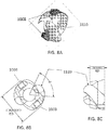
- the crushing elements 1008 are preferably blunt and substantially rectangular in shape.
- the crushing elements 1008 form a zero rake angle or a negative rake angle (as opposed to the positive rake angle of the blades 1110).
- the negative rake angle may range from at least 1, 5, 10, 15, 20, 25 30 degrees or more.
- the crushing elements 1008 may include other shapes, such as spherical, triangular, cylindrical, hexagonal, etc. While the body of a crushing element is generally blunt, the edges of the crushing element may be sharp to also assist in cutting through the occlusion.
- the one or more crushing elements 1008 may be located between the blades 1110 (as shown in FIGS. 8A- 8C ). In certain embodiments, the crushing elements 1008 are formed from a different material than the rest of the cutting element.
- the crushing elements 1008 are ideally formed from carbide metal, such as titanium carbide.
- the cutter assembly may comprise a second cutting element.
- the cutter assembly (506) may comprise a second cutting element (514).
- the second cutting element may be machined from a hard metallic material (e.g., 17-4 stainless) to include helical cutting flutes.
- the cutting flutes may be configured to have the same rake angle, relief angle, flute angle, and helix angle as the flutes of the first cutting element.
- the above-mentioned geometries of the first and second cutting elements may be identical, except that the second cutting element has more flutes than the first cutting element.
- the second cutting element may have double the number of flutes of the first cutting element; that is, four flutes are shown.
- the second cutting element is machined to include a hollow stem that fits within a center journal of the first cutting element.
- the second cutting element (514) may include a stem (538) around which the first cutting element (512) can be placed.
- FIG. 9 shows a perspective view of cutter assembly (506), in which the first (512) and second (514) cutting elements may be joined together (e.g., by adhesive or welding) in a rotationally aligned condition. In the aligned condition, two opposing cutting flutes (540) of the second cutting element (514) may be rotationally aligned with the two opposing cutting flutes (542) of the first cutting element (512).
- Their geometries may be matched during machining, and may act to cut and conveyed occlusive material proximally by the first cutting element into the housing and further convey the occlusive material more proximally into contact with the additional cutting blades of the second cutting element.
- the first cutting element (512) may cut occlusive material and convey the material to the second cutting element (514).
- the second cutting element (514) may further cut or macerate the occlusive materials into smaller particles.
- the occlusive materials may be continuously captured within the housing and conveyed proximally away from the targeted intravascular site.
- the helical cutting surfaces formed by the flutes may cut occlusive materials in the blood vessel and may convey the occlusive material from the blood vessel into the housing through the action of the helical flutes, and may do so without the assistance of any vacuum aspiration.
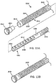
- the atherectomy apparatus includes an internal conveying member.
- the variation of atherectomy apparatus (500) shown in FIGS. 5A and 5B may comprise an internal conveyor (524).
- the internal conveying member may comprises a wire helically wound about the torque shaft in a direction common with the helical cutting surfaces of the cutter assembly.
- the cross-section of the internal conveyer member may be substantially circular or rectangular in shape.
- FIG. 9A illustrates the internal conveying member with a circular cross-section
- FIG. 9B illustrates the internal conveying member with a rectangular cross-section.
- a rectangular cross-section may increase the amount of contact between the conveyer and the internal surface of the catheter body, thereby increasing the conveying member's ability to move blockage particles down the length of the catheter.
- a cutter assembly cuts and captures occlusive material (e.g., when the helical flutes of a first and/or second cutting element conveys cut and captured occlusive materials to the conveying member)
- the conveying member may rotate in common with a torque shaft to convey the cut and captures occlusive materials it receives from the cutter assembly further back (proximally) along the catheter body into the handle.
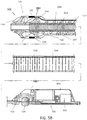
- FIG. 10 shows the variation of atherectomy apparatus (500) described above with respect to FIGS. 5A and 5B conveying and transferring occlusive material (1700) proximally through the apparatus.
- the occlusive materials carried back by the conveying element into the handle may be transferred into a discharge passage within the handle.
- a transfer propeller communicating with the discharge passage may be coupled to the torque shaft to rotate in common with the torque shaft, and may act to pump the cut, captured, and conveyed occlusive materials into the discharge passage.
- the discharge passage may include an external coupler (e.g., a leur connector) to couple the discharge passage to an external waste container.
- the cut and captured occlusive materials may be conveyed into the waste receptacle, and may be done so without need for vacuum aspiration.
- atherectomy apparatus (500) may comprise a transfer propeller (544), a discharge passage (546), and an external coupler (548), which may be connected to an external waste container (1702) as just described.
- the atherectomy apparatus may convey a fluid (1704) from the distal end of the device.
- the fluid (1704) maybe conveyed through an internal/guide wire lumen within the torque shaft (522).
- the atherectomy systems described here may comprise an atherectomy apparatus configured to selectively dynamically deflect at its distal end (e.g., near a cutter assembly).
- FIGS. 11A-11D show one variation of an atherectomy apparatus (1800) comprising a handle (1802), a catheter body (1804), and cutter assembly (1806). These elements may include any of the features previously described.
- the catheter body (1804) may be configured to dynamically deflect at its distal end (where the cutter assembly (1806) is carried) relative the central axis of the proximal catheter body (1804), as shown in FIG. 11C . This deflection may occur without axial advancement of the atherectomy apparatus.
- the atherectomy apparatus (1800) maybe configured to rotate the distal end of the apparatus while deflected about the central axis of the proximal catheter body (1804) to sweep the cutter assembly (1806) in an arc (1808) around the central axis, as shown in FIG. 11D .
- the ability of the atherectomy apparatus (1800) to sweep may allow for the cutter assembly to cut occlusive materials in a region larger than the outside diameter of the cutter assembly, as will be described in more detail below.
- the atherectomy apparatus (1800) maybe used in an atherectomy system including a guide wire (1810), and may be introduced into a blood vessel from an external percutaneous access site such as described previously with respect in FIGS. 4A-4D .
- the handle (1802) may be sized and configured to be securely held and manipulated by a caregiver outside an intravascular path in a manner previously described to advance the catheter along an intravascular.
- Image guidance e.g., CT, radiographic, or guidance mechanisms, or combinations thereof, may be used to aid the caregiver's manipulation.
- FIGS. 11A and 11B depict a variation of an atherectomy apparatus (2000) configured for use with the atherectomy systems described here.
- atherectomy apparatus (2000) may comprise a handle (2002), a catheter assembly (2004), and a cutter assembly (2006).
- the cutter assembly (2006) may comprise a ferrule (2008), a cutter housing (2010), a first cutting element (2012), and a second cutting element (2014).
- the cutting assemblies may have any elements or combination of elements as described in more detail above.
- the cutter housing (2010), first cutting element (2012), and second cutting element (2014) may have any of the elements and dimensions previously described.
- the first and second cutting elements may each comprise one or more helical cutting flutes having a rake angle between about 60 degrees and 80 degrees, a rake angle less than or equal to 10 degrees (in some of these variations, about 0 degrees), a flute angle between about 30 degrees and about 0 degrees, and a helix angle between about 30 degrees and about 60 degrees.
- the atherectomy apparatus (2000) may further comprise a drive motor (2016), which in some variations may be contained within a housing (2016) of the handle (2002). Also shown there is a torque shaft (2020) which may be coupled by gearing to the motor (2016) at a proximal end of the torque shaft (2020) and coupled to the second cutting element (2014) at a distal end of the torque shaft (2020).
- the torque shaft rotates the first (2012) and second (2014) cutting elements relative to the cutting assembly, such as described in more detail above. When the cutter rotates, it may cut and convey occlusive materials into the cutter housing (2010), and may do so without the use of any vacuum aspiration.
- the cutter housing (2010) may include an imaging assembly (2011) located thereon or embedded therein.
- the imaging assembly (2011) may be used to obtain real-time images of the occlusion (atheroma, plaque, thrombi, or emboli) prior to morcellation with the cutter (2012), during morcellation, and after morcellation to observe completeness of the procedure or whether more cutting is necessary to remove the blockage entirely or regain a suitable luminal opening.
- Suitable imaging assemblies include optical-acoustic imaging apparatus, intravascular ultrasound (IVUS), forward-looking intravascular ultrasound (FLIVUS) or optical coherence tomography (OCT).
- the imaging assembly (2011) is an ultrasound-based imaging assembly.
- the ultrasound imaging assembly may be a phased-array assembly, which includes a plurality of transducer elements.
- the imaging assembly (2011) may located/embedded on a portion of the housing (2010). In certain embodiments, the imaging assembly (2011) circumscribes the housing (314). In other embodiments, the imaging assembly (2011) is located on the catheter assembly (2032) proximal to the housing (2010).
- the imaging assembly 2011 is connected to one or more signal wires (2013), which are in turn connected to a signal processing apparatus.
- the signal wires (2013) transmit energy to the imaging assembly 2011 to emit imaging signals (such as ultrasound or optical signals) and transmit back signals (back-echo's) received from the imaging assembly to a signal processing apparatus and imaging console.
- the signal wires (2011) may run alongside an inner surface of the catheter assembly (2036) to the signal processing apparatus, or the signal wires (2011) may be incorporated into the catheter assembly (2036).
- the catheter assembly (2036) may define a separate lumen through which the signal wires (2013) may be routed.
- the atherectomy apparatus (2000) may comprise a catheter assembly (2004).
- the catheter assembly may have any suitable dimensions, such as described in more detail above.
- the catheter assembly (2004) may have an outer diameter less than or equal to the outer diameter of the cutter assembly (2006), In some of these variations, the catheter assembly (2004) may have an outer diameter less than the outer diameter of the cutter assembly (2006).
- a cutter assembly may have an outer diameter of 2.4 mm, and the catheter assembly may have an outer diameter of 2.2 mm.
- the catheter assembly may be configured to balance the column stiffness (pushability), tensile stiffness (pullability), torsional stiffness (torquability), and bending stiffness (trackability) of the catheter assembly, such as described in more detail below.
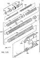
- the catheter assembly (2004) may comprise an outer catheter shaft (2026), an inner catheter shaft (2028), and a sweep tube assembly comprising an inner sweep tube (2030) and an outer sweep tube (2032).
- the outer catheter shaft (2026) may be formed in any suitable manner.
- the outer catheter shaft (2026) may be formed from a metal tube (e.g., a 304 stainless steel tube).
- the catheter bodies may have any number of zones/regions having different cut patterns (or in some zones, no cut pattern at all).
- one or more zones of the catheter body include helical cut patterns, threaded cut patterns, spiral cut patterns, or brickwork cut patterns.
- the outer catheter shaft can be lined or jacketed with a polymeric material, and further may be treated to produce hydrophilic, hydrophobic, or drug binding (heparin, antimicrobial) properties.
- the inner sweep tube (2030) may be fabricated from a metal tube formed (e.g., nitinol).
- the inner sweep tube (2030) may extend axially within the outer sweep tube (2032) and may have any suitable dimensions.
- the inner sweep tube (2030) may have an outer diameter of about 0.068 inches and an inner diameter of about 0.058 inches, and may have a total axial length of about 0.700 inches.+-.0.005 inches.
- the baseline bending stiffness of the inner sweep tube (2030) may be reduced to impart a preferential bending property in a predetermined direction.
- preferential bending maybe created using a pattern of open, dovetail cuts (2048).
- the closed, open, dovetail cuts (2048) may extend around a majority of the circumference (e.g., 350°) of the inner sweep tube (2030), which may leaving a spine (2050) of uncut material (e.g., about 10° of uncut material) that extends axially along the inner sweep tube (2030).
- the spine (2040) of the outer sweep tube (2032) and the spine (2050) of the inner sweep tube (2030) may be aligned such that spine (2040) and spine (2050) may be positioned on opposite sides of the catheter assembly.
- the dovetail cuts (2048) may have any suitable dimensions.
- the dovetail cuts (2048) each extend about 0.55 inches along the axis of the inner sweep tube (2030), and may include any number of dovetail cuts (2048).
- the inner sweep tube (2030) may comprise eight dovetail cuts, which may extend about 0.60" along the spine (2050).
- a tab (2052) of uncut material may extend beyond the distal end in alignment with the spine (2050), which may form an inner tube alignment key, as will be described in greater detail later.
- the laser-formed pattern of open cuts as just described permit preferential bending in the direction of the open cuts, away from the spine, until the open cuts come together and interfere in a distal to proximal succession.
- the open cuts may permit bending, but, as the bending continues, may resist bending as cuts close and interfere.
- a preformed bending radius may thereby be built into the inner sweep tube.
- the spine of the outer sweep tube (2042) may axially aligned with the open cuts (2048) of the inner sweep tube (2030) (i.e., the spine (2050) of the inner sweep tube (2030) may rotationally spaced 180° from the spine (2040) of the outer sweep tube (2032)).
- the proximal end of the inner sweep tube (2030) may include includes an open boot region (2054) facing at an angle (e.g., about 90°) from the pattern of open dovetail cuts.
- the open boot region (2054) maybe sized and configured to receive the distal end of the inner catheter shaft. It is the inner catheter shaft that may apply a bending force to the deflecting assemblage, as will be described in greater detail later.
- the inner catheter shaft (2028) of the atherectomy apparatus (2000) shown in FIGS. 12A and 12B may be sized and configured and fabricated in generally the same manner as any of the catheter bodies previously described (e.g., such as the catheter bodies described above).
- the inner catheter shaft (2028) may be formed from a metal tube (e.g., a 304 stainless steel tube), and may have dimensions suitable to allow the inner catheter shaft (2028) to fit within the outer catheter shaft and to accommodate passage of the torque shaft and conveyor element therein. Representative embodiments will be described.
- the tube of this material and configuration will provide a baseline column stiffness, tensile stiffness, torsional stiffness, and bending stiffness.
- the bending stiffness of the metal tube may be incrementally modulated along the length of the catheter body by creating zones of cut patterns along at least a portion of the length of the catheter body.
- the cut patterns may be formed in any suitable manner (e.g., via laser cutting), and the zones may impart a desired profile of bending stiffness over the length of the catheter body.
- cut pattern zones may be used to incrementally decrease the bending stiffness in a stepwise fashion from proximal end to distal end, to provide a minimum bending stiffness conducive to trackability at the distal end (where trackability is more desirable).
- the stepwise fashion in which the bending stiffness is decreased may be configured in a manner to help maintain the overall pushability, pullability, and torquability.
- Mixing the fluid with the occlusive materials may form a slurry, which may reduce the viscosity of the materials cut, captured, and conveyed from the vessel by the atherectomy apparatus to reduce the load imposed on the cutter assembly and facilitate the transfer of materials into the waste receptacle, as has been previously described.
- An increased gap may provide a greater volume of fluid to the cutter assembly, which may in turn improve the mechanical conveyance of occlusive materials away from the long total occlusion, thereby reducing the chance of cutter overload and stalling.
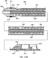
- the distal end of the inner catheter shaft may be coupled to the inner sweep tube, and may control deflection of the catheter assembly.
- the inner coupler (2038) may connect the inner catheter shaft (2028) to the inner sweep tube (2030) via the boot region (2054).
- the inner coupler (2038) may join the inner catheter shaft (2028) to the boot region (2054) in a manner that may transmit axial compression or tensile forces to the inner sweep tube (2030), but accommodates relative rotation between the inner catheter shaft (2028) and the inner sweep tube (2028) (i.e., the inner catheter shaft does not rotate when the outer catheter shaft is rotated to rotate the inner and outer sweep tubes).
- the coupling sleeve may be sized to locally step-up the distal diameter of the reduced diameter inner catheter shaft where it is coupled to the open boot of the inner sweep sleeve (i.e., the inner sweep tube need not be downsized when the inner catheter shaft is downsized), but it should be appreciated that in some instances the diameters of these components may be the same.
- the proximal end of the inner catheter shaft may be coupled to a control knob (2056) on the handle (2002).
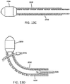
- the control knob (2056) may be advanced axially (distally) to advance the inner catheter shaft (2028) against the inner sweep tube (2030), to thereby apply a compressive force (as illustrated by arrow (2058) in FIG. 13D ) along the inner catheter shaft (2028) to the inner sweep tube (2030).
- the inner sweep tube may preferentially deflect in response to the applied compressive force in the direction of the open cut regions (as illustrated by arrow (2060) in FIG. 13D ).
- the control knob may be retracted axially (proximally) to relieve the compression force and apply a tensile force to the inner sweep tube, to straighten the delectable assembly, as shown in FIG. 13C .
- the preferential bending property of the inner sweep tube (in the direction of the open cuts) maybe unified with the preferential bending property of the concentric outer sweep tube (in the direction of the spine, away from the close cuts).
- the inner sweep tube may progressively bend in response to the bending force imparted by axial advancement of the inner catheter shaft, which may cause the open cuts of the inner sweep tube close and interfere first at the distal end, followed in succession by closing and interference of the proximal cuts down the length of the inner sweep tube.
- This may form a progressive distal-to-proximal stacking pattern as the inner sweep tube progressively bends until all cuts on the inner sweep tube close and intelfere to define the full bend radius (which in some variations may be about 1°).
- the outer sweep tube may bend in concert with the inner sweep tube, which may open the closed cuts in a distal-to-proximal stacking pattern.
- the inner and outer sweep tubes may channel the applied bending force in the direction of preferential bending, and may require less bending force for a given angular unit of deflection. Further, the successive distal-to- proximal stacking of the inner sweep tube cuts and opening of the outer sweep tube cuts may result in a uniform column stiffness applied to the cutter assembly regardless of the degree of deflection.
- the catheter assembly When deflected, the catheter assembly may apply an apposition force upon the cutter assembly, which may be created by opposing contact of the outer catheter assembly against an opposite vessel wall when the cutter assembly (deflected at the end of the catheter) contacts the occlusive materials at a desirable attack angle (as shown FIGS. 19B and 19C).
- the unified cooperation of the inner and outer sweep tubes during preferential bending may increase the magnitude of the apposition force, and may improve trackability and avoid trauma during advancement over the guide wire.
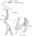
- FIGS. 14A-14F(5) depict a manner by which the atherectomy apparatus (2000) described above in relation to FIGS. 12A and 12B maybe actively and passively steered within a vessel.
- Active steering may be accomplished by advancement of the inner catheter shaft to bend the distal catheter assembly, accompanied by rotation of the catheter assembly, to point the cutter assembly in a preferred direction through an intravascular path, with or without a guide wire, and/or to point the cutter assembly toward a side wall of a vessel, with apposition, to cut and capture occlusive materials.
- the cutter assembly (2006) of atherectomy apparatus (2000) may be advanced into occlusive material (1900) in a vessel (1902), as shown in FIG. 14A .
- the catheter assembly (2004) When in place in the vessel, the catheter assembly (2004) may be deflected as shown in FIG. 14B .
- the deflected catheter assembly (2004) may be rotated to sweep the cutter assembly (2006), as shown in FIGS. 14C and 14D .
- subsequent advancement of the outer catheter shaft may apply enough compression force to cause deflection of the catheter assembly in the preferential direction (i.e., away from the inside radius of the bend).
- Continuance of the compression force upon the catheter body may cause the catheter body to follow the passively deflected catheter assembly away from inside radius of the bend and into the bend itself (see FIGS. 14F-3 and 14F-4 ).
- Successive bends in a tortuous path may be navigated in the same passive manner, by rotating the catheter body at each successive bend (e.g., by rotating the control knob or by rotation of the handle itself) to orient the preferential deflection of the catheter assembly away from the respective inner bend radius, and without the need to actively steer by manipulation of the inner catheter shaft.
- the catheter assembly (2004) may include one or more radiographic markings to indicate during radiographic guidance the orientation of the preferential bend direction of the catheter assembly, whether left, or right, or toward the viewer, or away from the viewer, al position of the cutter assembly without taking their eye off the radiographic image.
- FIGS. 15A and 15B depict another variation of an atherectomy apparatus (1600) described here.
- atherectomy apparatus (1600) may comprise a first catheter (1602), a second catheter (1604), and a cutter assembly (1605) attached to the first catheter (1602).
- the first catheter (1602) may be moveable relative to the second catheter (1604) to move a distal portion of the atherectomy apparatus (1600) between an undeflected configuration (as shown in FIG. 15A ) and a deflected configuration (as shown in FIG. 15B ).
- the first catheter (1602) maybe moveable within the second catheter (1604), although it should be appreciated that in other variations the second catheter (1604) may be slidable within the first catheter (1602).
- a distal portion (1606) of the second catheter (1604) may be shaped to take on a deflected position as shown in FIG. 15B .
- the deflected distal portion (1606) may comprise a double curve having a first proximal curve (1608) and a second distal curve (1610).
- the first curve (1608) may bend the distal portion (1606) away from the longitudinal axis (1612) of a proximal portion of the second catheter (1604), while the second curve (1610) may bend the distal portion (1606) in a direction toward the longitudinal axis (1612).
- the double-curve configuration of the distal portion (1606) may allow the second curve (1610) to contact or otherwise rest against a wall (1614) of a blood vessel (1616), as shown in FIG. 15B . Additionally, this may angle the cutter assembly (1605) toward an opposite vessel wall (1618) during cutting. In instances when the atherectomy apparatus (1600) is advanced over a guide wire (1620) as shown in FIG. 15B , the guide wire (1620) may contact the opposite vessel wall (1618) and may help to prevent the cutter assembly (1605) from directly contacting and/or damaging the vessel wall (1618). In some instances, the double-curve configuration of the distal portion (1606) may allow for advancement of the distal portion (1606) while deflected while minimizing the risk that the cutter assembly (1605) may catch on tissue and retroflex.
- the first catheter (1602) maybe moved relative to the second catheter (1604) to move the atherectomy apparatus between deflected and undeflected configurations.
- the first catheter (1602) may comprise a distal portion (1622) and a proximal portion (not shown), where the distal portion (1622) is more flexible than the proximal portion.
- the distal portion (1622) of the first catheter (1602) may be more flexible than the distal portion (1606) of the second catheter (1604), while the proximal portion of the first catheter (1602) may be stiffer than the distal portion (1606) of the second catheter (1604).
- the first catheter (1602) may be advanced such that the flexible distal portion (1622) of the first catheter (1602) extends beyond the distal end of the second catheter (1604), which may the proximal portion of the first catheter (1602) within the distal portion (1606) of the second catheter (1604) (or around the distal portion (1606) of the second catheter (1604) in variations where the second catheter (1604) is positioned inside the first catheter (1602).
- the proximal portion of the first catheter (1602) is stiffer than the distal portion of the second catheter (1604), axial alignment of these catheter segments may cause the proximal portion of the first catheter (1602) to straighten out the curves of the distal portion of the second catheter (1604), thereby placing the atherectomy apparatus (1600) in an undeflected configuration, as shown in FIG. 15A .
- the flexible distal portion of the first catheter (1602) extends beyond the distal portion of the second catheter (1604) when in an undeflected configuration, it may be used to track the cutter assembly (1605) along a guide wire during navigation of the atherectomy apparatus (1600) through the vasculature.
- the atherectomy apparatus (1600) maybe advanced while cutting to cut along the path of the guide wire (which may be a straight path in some instances), as described in more detail below.
- the atherectomy apparatus (1600) may then be withdrawn and deflected to cut a larger path through occlusive material (not shown), such as described below.
- the first catheter (1602) may be withdrawn to place the flexible distal portion (1622) of the first catheter (1602) in axial alignment with the distal portion (1606) of the second catheter (1604). Because the distal portion (1606) of the second catheter (1604) is stiffer than the distal portion (1622) of the first catheter (1602), the second catheter (1604) may cause the flexible distal portion (1622) of the first catheter (1602) to take on the dual-curve configuration described above with respect to FIG. 15B .
- Atherectomy systems of the invention include an imaging assembly (e.g., 311, 511, 2011) that provides for guided cutting and removal of occlusions.
- the imaging assembly may be and ultrasound imaging assembly, photoacoustic imaging assembly, optical coherence tomography imaging assembly, or combination thereof.
- the systems of the invention incorporate focused acoustic computed tomography (FACT), ⁇ which is described in WO2014/109879 .
- the imaging assembly may be an intravascular ultrasound (IVUS) imaging assembly.
- the ultrasound probe can either be either a rotating transducer or an array of circumferentially positioned transducers.
- the proximal end of the catheter is attached to computerized imaging console.
- the IVUS imaging element i.e. ultrasound probe
- the imaging transducers and imaging collectors are coupled to signal lines that run through the length of the catheter and couple to the computerized ultrasound equipment.
- Imaging assembly may use the same piezoelectric components to produce and receive the ultrasonic energy, for example, by using pulsed ultrasound. That is, the imaging transducer and the imaging collectors are the same.
- Another alternative embodiment may incorporate ultrasound absorbing materials and ultrasound lenses to increase signal to noise.
- IVUS data is typically gathered in segments where each segment represents an angular portion of an IVUS image. Thus, it takes a plurality of segments (or a set of IVUS data) to image an entire cross-section of a vascular object. Furthermore, multiple sets of IVUS data are typically gathered from multiple locations within a vascular object (e.g., by moving the transducer linearly through the vessel). These multiple sets of data can then be used to create a plurality of two- dimensional (2D) images or one three-dimensional (3D) image.
- 2D two- dimensional
- IVUS imaging assemblies and processing of IVUS data are described in further detail in, for example, Yock, U.S. Pat. Nos. 4,794,931 , 5,000,185 , and 5,313,949 ; Sieben et al., U.S. Pat. Nos. 5,243,988 , and 5,353,798 ; Crowley et al., U.S. Pat. No. 4,951,677 ; Pomeranz, U.S. Pat. No. 5,095,911 , Griffith et al., U.S. Pat. No. 4,841,977 , Maroney et al., U.S. Pat. No. 5,373,849 , Born et al., U.S. Pat. No.
- OCT is a medical imaging methodology using a miniaturized near infrared light-emitting probe.
- A. an optical signal acquisition and processing method, it captures micrometer--resolution, three-dimensional images from within optical scattering media (e.g., biological tissue).
- optical scattering media e.g., biological tissue.
- OCT allows the application of intelferometric technology to see from inside, for example, blood vessels, visualizing the endothelium (inner wall) of blood vessels in living individuals.
- a light source delivers a beam of light to an imaging device to image target tissue.
- Light sources can include pulsating light sources or lasers, continuous wave light sources or lasers, tunable lasers, broadband light source, or multiple tunable laser.
- Within the light source is an optical amplifier and a tunable filter that allows a user to select a wavelength of light to be amplified. Wavelengths commonly used in medical applications include near--infrared light, for example between about 800 nm and about 1700 nm.
- aspects of the invention on may obtain imaging data from an OCT system, including OCT systems that operate in either the time domain or frequency (high definition) domain.
- OCT systems that operate in either the time domain or frequency (high definition) domain.
- Basic differences between time-domain OCT and frequency-domain OCT is that in time-domain OCT, the scanning mechanism is a movable minor, which is scanned as a function of time during the image acquisition.
- the frequency-domain OCT there are no moving parts and the image is scanned as a function of frequency or wavelength.
- an interference spectrum is obtained by moving the scanning mechanism, such as a reference mirror, longitudinally to change the reference path and match multiple optical paths due to reflections within the sample.
- the signal giving the reflectivity is sampled over time, and light traveling at a specific distance creates interference in the detector. Moving the scanning mechanism laterally (or rotationally) across the sample produces two-dimensional and three-dimensional images.
- a light source capable of emitting a range of optical frequencies excites an interferometer, the interferometer combines the light returned from a sample with a reference beam of light from the same source, and the intensity of the combined light is recorded as a function of optical frequency to form an interference spectrum.
- a Fourier transform of the interference spectrum provides the reflectance distribution along the depth within the sample.
- SD-OCT spectral- domain OCT
- Spectral Radar ⁇ Optics letters, Vol. 21 No. 14 (1996) 1087-1089
- a grating or prism or other means is used to disperse the output of the interferometer into its optical frequency components.
- the intensities of these separated components are measured using an array of optical detectors, each detector receiving an optical frequency or a fractional range of optical frequencies.
- the set of measurements from these optical detectors forms an interference spectrum ( Smith, L.M. and C.C. Dobson, Applied Optics 28: 3339-3342 ), wherein the distance to a scatterer is determined by the wavelength dependent fringe spacing within the power spectrum.
- SD-OCT has enabled the determination of distance and scatteling intensity of multiple scatters lying along the illumination axis by analyzing a single the exposure of an array of optical detectors so that no scanning in depth is necessary.
- the light source emits a broad range of optical frequencies simultaneously.
- time domain systems and frequency domain system s can further vary in type based upon the optical layout of the systems: common beam path systems and differential beam path systenls.
- a common beam path system sends all produced light through a single optical fiber to generate a reference signal and a sample signal whereas a differential beam path system splits the produced light such that a portion of the light is directed to the sample and the other portion is directed to a reference surface.
- Common beam path systems are described in U.S. Pat. 7,999,938 ; U.S. Pat 7,995,210 ; and U.S. Pat. 7,787,127 and differential beam path systems are described in U.S. Pat. 7,783,337 ; US Pat. 6,134,003 ; and U.S. Pat. 6,421,164 .
- the obtained image data from the imaging assembly of the atherectomy systems described herein is processed to characterize biological material and/or foreign material (i.e. the occlusion) within the vessels.
- the characterization allows one to determine with specificity the type of occlusion within the vessel (e.g. plaque or clot) and the severity of the occlusion, e.g., whether the occlusion is calcified, fibrous, or soft.
- the processing step may be performed by an image processing computer operably connected to the imaging assembly via signal wires.
- a system controller 1600 is interfaced to an image processing computer 1060 that is capable of synthesizing the images into easy-to-understand images.
- the image processing computer 1060 is also configured to analyze the spectrum of the collected data to determine tissue characteristics, a.k.a. virtual histology. As discussed in greater detail below, the image processing will deconvolve the reflected acoustic waves or interfered infrared waves to produce distance and/or tissue measurements, and those distance and tissue measurements can be used to produce an image, for example an IVUS image or an OCT image.
- Flow detection and tissue characterization algorithms including motion-detection algorithms (such as CHROMAFLO (IVUS fluid flow display software; Volcano Corporation), Q-Flow, B-Flow, Delta-Phase, Doppler, Power Doppler, etc.), temporal algorithms, harmonic signal processing, can be used to differentiate blood speckle from other structural tissue, and therefore enhance images where ultrasound energy back scattered from blood causes image artifacts.
- motion-detection algorithms such as CHROMAFLO (IVUS fluid flow display software; Volcano Corporation
- Q-Flow Q-Flow
- B-Flow Q-Flow
- Delta-Phase Doppler
- Power Doppler Power Doppler
- harmonic signal processing can be used to differentiate blood speckle from other structural tissue, and therefore enhance images where ultrasound energy back scattered from blood causes image artifacts.
- the image processing may additionally include spectral analysis, i.e., examining the energy of the returned acoustic signal at various frequencies. Spectral analysis is useful for determining the nature of the tissue and the presence of foreign objects.
- a plaque deposit or neointimal hyperplasia for example, will typically have different spectral signatures than nearby vascular tissue without such plaque or neointimal hyperplasia, allowing discrimination between healthy and diseased tissue.
- a metal surface such as an AV graft, will have a different spectral signal.
- Such signal processing may additionally include statistical processing (e.g., averaging, filtering, or the like) of the returned ultrasound signal in the time domain.
- the spectral analysis can also be used to determine the tissue lumen/blood border.
- image processing may facilitate use of the images or identification of features of interest.
- the border of a lumen may be highlighted or thrombus or plaque deposits may be displayed in a visually different manner (e.g., by assigning thrombus a discernible color) than other portions of the image.
- Other image enhancement techniques known in the art of imaging may also be applied.
- similar techniques can be used to discriminate between vulnerable plaque and other plaque, or to enhance the displayed image by providing visual indicators to assist the user in discliminating between vulnerable and other plaque.
- Other measurements, such as flow rates or pressure may be displayed using color mapping or by displaying numerical values.
- the open cross-sectional area of the lumen is colorized with red to represent the blood flux.
Landscapes
- Health & Medical Sciences (AREA)
- Life Sciences & Earth Sciences (AREA)
- Surgery (AREA)
- Animal Behavior & Ethology (AREA)
- Public Health (AREA)
- Engineering & Computer Science (AREA)
- Biomedical Technology (AREA)
- Heart & Thoracic Surgery (AREA)
- Medical Informatics (AREA)
- Molecular Biology (AREA)
- Veterinary Medicine (AREA)
- General Health & Medical Sciences (AREA)
- Nuclear Medicine, Radiotherapy & Molecular Imaging (AREA)
- Physics & Mathematics (AREA)
- Biophysics (AREA)
- Pathology (AREA)
- Radiology & Medical Imaging (AREA)
- Vascular Medicine (AREA)
- Gynecology & Obstetrics (AREA)
- Surgical Instruments (AREA)
- Endoscopes (AREA)
- Ultra Sonic Daignosis Equipment (AREA)
Applications Claiming Priority (2)
| Application Number | Priority Date | Filing Date | Title |
|---|---|---|---|
| US201562118585P | 2015-02-20 | 2015-02-20 | |
| PCT/IB2016/050448 WO2016132241A1 (en) | 2015-02-20 | 2016-01-29 | Atherectomy apparatus with imaging |
Publications (2)
| Publication Number | Publication Date |
|---|---|
| EP3258863A1 EP3258863A1 (en) | 2017-12-27 |
| EP3258863B1 true EP3258863B1 (en) | 2020-09-16 |
Family
ID=55299699
Family Applications (1)
| Application Number | Title | Priority Date | Filing Date |
|---|---|---|---|
| EP16702817.4A Active EP3258863B1 (en) | 2015-02-20 | 2016-01-29 | Atherectomy apparatus with imaging |
Country Status (5)
| Country | Link |
|---|---|
| US (1) | US20160242808A1 (zh) |
| EP (1) | EP3258863B1 (zh) |
| JP (1) | JP6772161B2 (zh) |
| CN (1) | CN107530049B (zh) |
| WO (1) | WO2016132241A1 (zh) |
Families Citing this family (15)
| Publication number | Priority date | Publication date | Assignee | Title |
|---|---|---|---|---|
| EP4230262A3 (en) | 2015-06-24 | 2023-11-22 | The Regents Of The University Of Michigan | Histotripsy therapy systems for the treatment of brain tissue |
| JP6855490B2 (ja) * | 2016-08-30 | 2021-04-07 | テルモ株式会社 | 医療デバイス |
| JP7019582B2 (ja) | 2016-09-16 | 2022-02-15 | テルモ株式会社 | 医療デバイス |
| US20180311508A1 (en) * | 2017-03-02 | 2018-11-01 | Circuit Therapeutics, Inc. | System for optogenetic therapy |
| US10987131B2 (en) | 2017-05-25 | 2021-04-27 | Coopersurgical, Inc. | Tissue containment systems and related methods |
| WO2019188918A1 (ja) * | 2018-03-28 | 2019-10-03 | テルモ株式会社 | 医療デバイスおよび処置用法 |
| WO2020089415A1 (en) * | 2018-11-01 | 2020-05-07 | Koninklijke Philips N.V. | Atherectomy devices including pre-shaped and curved distal portions and methods |
| WO2020113083A1 (en) | 2018-11-28 | 2020-06-04 | Histosonics, Inc. | Histotripsy systems and methods |
| CN113301856A (zh) * | 2019-01-07 | 2021-08-24 | 皇家飞利浦有限公司 | 用于管腔内超声成像组件的增加柔性的基板 |
| EP3914169A1 (en) * | 2019-01-21 | 2021-12-01 | Koninklijke Philips N.V. | Vascular treatment systems and devices including intravascular imaging capabilities |
| EP3968876B1 (en) * | 2019-05-17 | 2023-07-12 | Koninklijke Philips N.V. | Atherectomy devices including positive and negative rake angle cutting blades |
| CN114222536A (zh) * | 2019-06-18 | 2022-03-22 | 皇家飞利浦有限公司 | 包括多个远侧切割特征的斑块切除装置 |
| CA3169465A1 (en) | 2020-01-28 | 2021-08-05 | The Regents Of The University Of Michigan | Systems and methods for histotripsy immunosensitization |
| CN113017780B (zh) * | 2021-03-02 | 2022-03-08 | 哈尔滨医科大学 | 一种集成超声成像与腔内斑块旋切术的导管系统 |
| CN115429392A (zh) * | 2022-10-08 | 2022-12-06 | 福州大学 | 基于超声反馈的血管钙化组织识别及去除装置和使用方法 |
Family Cites Families (59)
| Publication number | Priority date | Publication date | Assignee | Title |
|---|---|---|---|---|
| US4794931A (en) | 1986-02-28 | 1989-01-03 | Cardiovascular Imaging Systems, Inc. | Catheter apparatus, system and method for intravascular two-dimensional ultrasonography |
| US5000185A (en) | 1986-02-28 | 1991-03-19 | Cardiovascular Imaging Systems, Inc. | Method for intravascular two-dimensional ultrasonography and recanalization |
| US4841977A (en) | 1987-05-26 | 1989-06-27 | Inter Therapy, Inc. | Ultra-thin acoustic transducer and balloon catheter using same in imaging array subassembly |
| US4917097A (en) | 1987-10-27 | 1990-04-17 | Endosonics Corporation | Apparatus and method for imaging small cavities |
| US4951677A (en) | 1988-03-21 | 1990-08-28 | Prutech Research And Development Partnership Ii | Acoustic imaging catheter and the like |
| NL8902559A (nl) | 1989-10-16 | 1991-05-16 | Du Med Bv | Intra-luminale inrichting. |
| US5240003A (en) | 1989-10-16 | 1993-08-31 | Du-Med B.V. | Ultrasonic instrument with a micro motor having stator coils on a flexible circuit board |
| US5095911A (en) | 1990-05-18 | 1992-03-17 | Cardiovascular Imaging Systems, Inc. | Guidewire with imaging capability |
| US5135486A (en) | 1990-08-31 | 1992-08-04 | Endosonics Corporation | Self-venting balloon dilitation catheter |
| US5167233A (en) | 1991-01-07 | 1992-12-01 | Endosonics Corporation | Dilating and imaging apparatus |
| US5353798A (en) | 1991-03-13 | 1994-10-11 | Scimed Life Systems, Incorporated | Intravascular imaging apparatus and methods for use and manufacture |
| US5243988A (en) | 1991-03-13 | 1993-09-14 | Scimed Life Systems, Inc. | Intravascular imaging apparatus and methods for use and manufacture |
| US6134003A (en) | 1991-04-29 | 2000-10-17 | Massachusetts Institute Of Technology | Method and apparatus for performing optical measurements using a fiber optic imaging guidewire, catheter or endoscope |
| US6111645A (en) | 1991-04-29 | 2000-08-29 | Massachusetts Institute Of Technology | Grating based phase control optical delay line |
| JP3479069B2 (ja) | 1991-04-29 | 2003-12-15 | マサチューセッツ・インステチュート・オブ・テクノロジー | 光学的イメージ形成および測定の方法および装置 |
| US5183048A (en) | 1991-06-24 | 1993-02-02 | Endosonics Corporation | Method and apparatus for removing artifacts from an ultrasonically generated image of a small cavity |
| US5373845A (en) | 1992-05-22 | 1994-12-20 | Echo Cath, Ltd. | Apparatus and method for forward looking volume imaging |
| US5373849A (en) | 1993-01-19 | 1994-12-20 | Cardiovascular Imaging Systems, Inc. | Forward viewing imaging catheter |
| US5368037A (en) | 1993-02-01 | 1994-11-29 | Endosonics Corporation | Ultrasound catheter |
| US5453575A (en) | 1993-02-01 | 1995-09-26 | Endosonics Corporation | Apparatus and method for detecting blood flow in intravascular ultrasonic imaging |
| US6381350B1 (en) | 1999-07-02 | 2002-04-30 | The Cleveland Clinic Foundation | Intravascular ultrasonic analysis using active contour method and system |
| WO2001015609A1 (en) * | 1999-08-31 | 2001-03-08 | Fox Hollow Technologies | Atherectomy catheter with a rotating and telescoping cutter |
| US6200268B1 (en) | 1999-09-10 | 2001-03-13 | The Cleveland Clinic Foundation | Vascular plaque characterization |
| US7074188B2 (en) | 2002-08-26 | 2006-07-11 | The Cleveland Clinic Foundation | System and method of characterizing vascular tissue |
| US7359554B2 (en) | 2002-08-26 | 2008-04-15 | Cleveland Clinic Foundation | System and method for identifying a vascular border |
| CN100401994C (zh) * | 2002-10-18 | 2008-07-16 | 阿里耶·谢尔 | 配有成像导丝的动脉粥样硬化斑移除系统 |
| US7175597B2 (en) | 2003-02-03 | 2007-02-13 | Cleveland Clinic Foundation | Non-invasive tissue characterization system and method |
| US6943881B2 (en) | 2003-06-04 | 2005-09-13 | Tomophase Corporation | Measurements of optical inhomogeneity and other properties in substances using propagation modes of light |
| WO2005041748A2 (en) * | 2003-09-12 | 2005-05-12 | Minnow Medical, Llc | Selectable eccentric remodeling and/or ablation of atherosclerotic material |
| US7215802B2 (en) | 2004-03-04 | 2007-05-08 | The Cleveland Clinic Foundation | System and method for vascular border detection |
| US7397935B2 (en) | 2004-05-10 | 2008-07-08 | Mediguide Ltd. | Method for segmentation of IVUS image sequences |
| EP2278266A3 (en) | 2004-11-24 | 2011-06-29 | The General Hospital Corporation | Common-Path Interferometer for Endoscopic OCT |
| EP1868754A2 (en) * | 2005-03-30 | 2007-12-26 | Lumend, Inc. | Catheter systems for crossing total occlusions in vasculature |
| JP2008539908A (ja) * | 2005-05-12 | 2008-11-20 | コンピュメディクス メディカル イノベーション ピーティーワイ リミテッド | 超音波診断および治療装置 |
| EP1887946A2 (en) | 2005-06-06 | 2008-02-20 | The Board Of Regents, The University Of Texas System | Oct using spectrally resolved bandwidth |
| JP5600241B2 (ja) | 2005-10-13 | 2014-10-01 | ヴォルケイノウ・コーポレーション | コンポーネントベースのカテーテル・ラボラトリ血管内超音波システム |
| WO2007047974A2 (en) | 2005-10-20 | 2007-04-26 | Board Of Regents, The University Of Texas System | Rotating optical catheter tip for optical coherence tomography |
| US8125648B2 (en) | 2006-06-05 | 2012-02-28 | Board Of Regents, The University Of Texas System | Polarization-sensitive spectral interferometry |
| US20090018566A1 (en) * | 2006-06-30 | 2009-01-15 | Artheromed, Inc. | Atherectomy devices, systems, and methods |
| US9314263B2 (en) * | 2006-06-30 | 2016-04-19 | Atheromed, Inc. | Atherectomy devices, systems, and methods |
| US8289284B2 (en) | 2007-08-09 | 2012-10-16 | Volcano Corporation | Controller user interface for a catheter lab intravascular ultrasound system |
| US8108030B2 (en) | 2006-10-20 | 2012-01-31 | Board Of Regents, The University Of Texas System | Method and apparatus to identify vulnerable plaques with thermal wave imaging of heated nanoparticles |
| WO2008091961A2 (en) | 2007-01-23 | 2008-07-31 | Volcano Corporation | Optical coherence tomography implementation |
| CA2692463A1 (en) * | 2007-06-29 | 2009-01-08 | Atheromed, Inc. | Atherectomy devices, systems, and methods |
| WO2009009802A1 (en) | 2007-07-12 | 2009-01-15 | Volcano Corporation | Oct-ivus catheter for concurrent luminal imaging |
| EP2191227A4 (en) | 2007-08-10 | 2017-04-19 | Board of Regents, The University of Texas System | Forward-imaging optical coherence tomography (oct) systems and probe |
| US7787127B2 (en) | 2007-10-15 | 2010-08-31 | Michael Galle | System and method to determine chromatic dispersion in short lengths of waveguides using a common path interferometer |
| US8784440B2 (en) * | 2008-02-25 | 2014-07-22 | Covidien Lp | Methods and devices for cutting tissue |
| US20090284332A1 (en) | 2008-05-15 | 2009-11-19 | Silicon Valley Medical Instruments, Inc. | Ivus system with rotary capacitive coupling |
| BRPI1010595A2 (pt) * | 2009-05-14 | 2017-05-16 | Tyco Healthcare | cateteres de aterectomia facilmente limpaveis e metodos para uso |
| EP2506783B1 (en) * | 2009-12-02 | 2016-06-29 | Covidien LP | Methods and devices for cutting tissue |
| CA2803992C (en) * | 2010-07-01 | 2018-03-20 | Avinger, Inc. | Atherectomy catheters with longitudinally displaceable drive shafts |
| KR20150020240A (ko) * | 2010-11-11 | 2015-02-25 | 코비디엔 엘피 | 촬영용 가요성 디벌킹 카테터와, 사용 및 제조 방법 |
| EP2765930B1 (en) * | 2011-10-13 | 2018-09-26 | Atheromed, Inc. | Atherectomy apparatus |
| WO2014109879A1 (en) | 2013-01-08 | 2014-07-17 | Volcano Corporation | Method for focused acoustic computed tomography (fact) |
| US20140276059A1 (en) * | 2013-03-12 | 2014-09-18 | Volcano Corporation | Externally imaging a body structure within a patient |
| US20140276015A1 (en) * | 2013-03-14 | 2014-09-18 | Volcano Corporation | Devices and methods for imaging and crossing occluded vessels |
| WO2015017114A2 (en) * | 2013-07-31 | 2015-02-05 | Atheromed, Inc. | Atherectomy devices |
| CN103462646B (zh) * | 2013-09-17 | 2014-12-10 | 浙江大学 | 一种集成血管内超声(ivus)影像和数字减影(dsa)影像的一体化离线处理系统 |
-
2016
- 2016-01-29 JP JP2017543368A patent/JP6772161B2/ja active Active
- 2016-01-29 CN CN201680022621.7A patent/CN107530049B/zh active Active
- 2016-01-29 EP EP16702817.4A patent/EP3258863B1/en active Active
- 2016-01-29 WO PCT/IB2016/050448 patent/WO2016132241A1/en active Application Filing
- 2016-02-19 US US15/048,042 patent/US20160242808A1/en active Pending
Non-Patent Citations (1)
| Title |
|---|
| None * |
Also Published As
| Publication number | Publication date |
|---|---|
| JP2018511361A (ja) | 2018-04-26 |
| CN107530049B (zh) | 2021-06-04 |
| US20160242808A1 (en) | 2016-08-25 |
| WO2016132241A1 (en) | 2016-08-25 |
| EP3258863A1 (en) | 2017-12-27 |
| CN107530049A (zh) | 2018-01-02 |
| JP6772161B2 (ja) | 2020-10-21 |
Similar Documents
| Publication | Publication Date | Title |
|---|---|---|
| EP3258863B1 (en) | Atherectomy apparatus with imaging | |
| JP6865691B2 (ja) | デュアルルーメン診断カテーテル | |
| US20190083717A1 (en) | Devices and methods for forming vascular access | |
| US20140276684A1 (en) | Atherectomy methods using coregistered sets of data | |
| EP2765930B1 (en) | Atherectomy apparatus | |
| US20150297097A1 (en) | Vascular access evaluation and treatment | |
| US20140200438A1 (en) | Intraluminal imaging system | |
| US20140180069A1 (en) | Intraluminal imaging system | |
| EP2934330B1 (en) | Implant delivery system and implants | |
| US20150297259A1 (en) | Catheter assembly for vascular access site creation | |
| US20140180055A1 (en) | Aspirating and removing biological material | |
| JP6747977B2 (ja) | イメージング及び処理デバイス | |
| JP7369865B2 (ja) | 血管内超音波画像を処理するためのシステム | |
| JP2021529588A (ja) | 内部的に超音波支援された治療薬の局所的送達 | |
| WO2015074045A2 (en) | Therapeutic delivery catheter with imaging and tissue characterization | |
| US20140276024A1 (en) | Imaging and delivering thrombolytic agents to biological material inside a vessel | |
| WO2014100194A1 (en) | Imaging and removing biological material | |
| US20140180119A1 (en) | Intraluminal imaging system | |
| US20230181016A1 (en) | Imaging system | |
| JP2021529038A (ja) | 活性治療薬の外部標的化送達 |
Legal Events
| Date | Code | Title | Description |
|---|---|---|---|
| STAA | Information on the status of an ep patent application or granted ep patent |
Free format text: STATUS: THE INTERNATIONAL PUBLICATION HAS BEEN MADE |
|
| PUAI | Public reference made under article 153(3) epc to a published international application that has entered the european phase |
Free format text: ORIGINAL CODE: 0009012 |
|
| STAA | Information on the status of an ep patent application or granted ep patent |
Free format text: STATUS: REQUEST FOR EXAMINATION WAS MADE |
|
| 17P | Request for examination filed |
Effective date: 20170920 |
|
| AK | Designated contracting states |
Kind code of ref document: A1 Designated state(s): AL AT BE BG CH CY CZ DE DK EE ES FI FR GB GR HR HU IE IS IT LI LT LU LV MC MK MT NL NO PL PT RO RS SE SI SK SM TR |
|
| AX | Request for extension of the european patent |
Extension state: BA ME |
|
| DAV | Request for validation of the european patent (deleted) | ||
| DAX | Request for extension of the european patent (deleted) | ||
| STAA | Information on the status of an ep patent application or granted ep patent |
Free format text: STATUS: EXAMINATION IS IN PROGRESS |
|
| 17Q | First examination report despatched |
Effective date: 20190204 |
|
| RAP1 | Party data changed (applicant data changed or rights of an application transferred) |
Owner name: KONINKLIJKE PHILIPS N.V. Owner name: VOLCANO CORPORATION |
|
| GRAP | Despatch of communication of intention to grant a patent |
Free format text: ORIGINAL CODE: EPIDOSNIGR1 |
|
| STAA | Information on the status of an ep patent application or granted ep patent |
Free format text: STATUS: GRANT OF PATENT IS INTENDED |
|
| RIC1 | Information provided on ipc code assigned before grant |
Ipc: A61B 90/00 20160101ALN20200326BHEP Ipc: A61B 17/3207 20060101AFI20200326BHEP Ipc: A61B 17/22 20060101ALN20200326BHEP |
|
| INTG | Intention to grant announced |
Effective date: 20200416 |
|
| RIC1 | Information provided on ipc code assigned before grant |
Ipc: A61B 17/3207 20060101AFI20200403BHEP Ipc: A61B 17/22 20060101ALN20200403BHEP Ipc: A61B 90/00 20160101ALN20200403BHEP |
|
| GRAS | Grant fee paid |
Free format text: ORIGINAL CODE: EPIDOSNIGR3 |
|
| GRAA | (expected) grant |
Free format text: ORIGINAL CODE: 0009210 |
|
| STAA | Information on the status of an ep patent application or granted ep patent |
Free format text: STATUS: THE PATENT HAS BEEN GRANTED |
|
| AK | Designated contracting states |
Kind code of ref document: B1 Designated state(s): AL AT BE BG CH CY CZ DE DK EE ES FI FR GB GR HR HU IE IS IT LI LT LU LV MC MK MT NL NO PL PT RO RS SE SI SK SM TR |
|
| REG | Reference to a national code |
Ref country code: GB Ref legal event code: FG4D |
|
| REG | Reference to a national code |
Ref country code: CH Ref legal event code: EP |
|
| REG | Reference to a national code |
Ref country code: DE Ref legal event code: R096 Ref document number: 602016044045 Country of ref document: DE |
|
| REG | Reference to a national code |
Ref country code: IE Ref legal event code: FG4D |
|
| REG | Reference to a national code |
Ref country code: AT Ref legal event code: REF Ref document number: 1313426 Country of ref document: AT Kind code of ref document: T Effective date: 20201015 |
|
| RAP2 | Party data changed (patent owner data changed or rights of a patent transferred) |
Owner name: PHILIPS IMAGE GUIDED THERAPY CORPORATION Owner name: KONINKLIJKE PHILIPS N.V. |
|
| PG25 | Lapsed in a contracting state [announced via postgrant information from national office to epo] |
Ref country code: NO Free format text: LAPSE BECAUSE OF FAILURE TO SUBMIT A TRANSLATION OF THE DESCRIPTION OR TO PAY THE FEE WITHIN THE PRESCRIBED TIME-LIMIT Effective date: 20201216 Ref country code: BG Free format text: LAPSE BECAUSE OF FAILURE TO SUBMIT A TRANSLATION OF THE DESCRIPTION OR TO PAY THE FEE WITHIN THE PRESCRIBED TIME-LIMIT Effective date: 20201216 Ref country code: GR Free format text: LAPSE BECAUSE OF FAILURE TO SUBMIT A TRANSLATION OF THE DESCRIPTION OR TO PAY THE FEE WITHIN THE PRESCRIBED TIME-LIMIT Effective date: 20201217 Ref country code: SE Free format text: LAPSE BECAUSE OF FAILURE TO SUBMIT A TRANSLATION OF THE DESCRIPTION OR TO PAY THE FEE WITHIN THE PRESCRIBED TIME-LIMIT Effective date: 20200916 Ref country code: HR Free format text: LAPSE BECAUSE OF FAILURE TO SUBMIT A TRANSLATION OF THE DESCRIPTION OR TO PAY THE FEE WITHIN THE PRESCRIBED TIME-LIMIT Effective date: 20200916 Ref country code: FI Free format text: LAPSE BECAUSE OF FAILURE TO SUBMIT A TRANSLATION OF THE DESCRIPTION OR TO PAY THE FEE WITHIN THE PRESCRIBED TIME-LIMIT Effective date: 20200916 |
|
| REG | Reference to a national code |
Ref country code: AT Ref legal event code: MK05 Ref document number: 1313426 Country of ref document: AT Kind code of ref document: T Effective date: 20200916 |
|
| REG | Reference to a national code |
Ref country code: NL Ref legal event code: MP Effective date: 20200916 |
|
| PG25 | Lapsed in a contracting state [announced via postgrant information from national office to epo] |
Ref country code: RS Free format text: LAPSE BECAUSE OF FAILURE TO SUBMIT A TRANSLATION OF THE DESCRIPTION OR TO PAY THE FEE WITHIN THE PRESCRIBED TIME-LIMIT Effective date: 20200916 Ref country code: LV Free format text: LAPSE BECAUSE OF FAILURE TO SUBMIT A TRANSLATION OF THE DESCRIPTION OR TO PAY THE FEE WITHIN THE PRESCRIBED TIME-LIMIT Effective date: 20200916 |
|
| REG | Reference to a national code |
Ref country code: LT Ref legal event code: MG4D |
|
| PG25 | Lapsed in a contracting state [announced via postgrant information from national office to epo] |
Ref country code: LT Free format text: LAPSE BECAUSE OF FAILURE TO SUBMIT A TRANSLATION OF THE DESCRIPTION OR TO PAY THE FEE WITHIN THE PRESCRIBED TIME-LIMIT Effective date: 20200916 Ref country code: CZ Free format text: LAPSE BECAUSE OF FAILURE TO SUBMIT A TRANSLATION OF THE DESCRIPTION OR TO PAY THE FEE WITHIN THE PRESCRIBED TIME-LIMIT Effective date: 20200916 Ref country code: RO Free format text: LAPSE BECAUSE OF FAILURE TO SUBMIT A TRANSLATION OF THE DESCRIPTION OR TO PAY THE FEE WITHIN THE PRESCRIBED TIME-LIMIT Effective date: 20200916 Ref country code: SM Free format text: LAPSE BECAUSE OF FAILURE TO SUBMIT A TRANSLATION OF THE DESCRIPTION OR TO PAY THE FEE WITHIN THE PRESCRIBED TIME-LIMIT Effective date: 20200916 Ref country code: PT Free format text: LAPSE BECAUSE OF FAILURE TO SUBMIT A TRANSLATION OF THE DESCRIPTION OR TO PAY THE FEE WITHIN THE PRESCRIBED TIME-LIMIT Effective date: 20210118 Ref country code: EE Free format text: LAPSE BECAUSE OF FAILURE TO SUBMIT A TRANSLATION OF THE DESCRIPTION OR TO PAY THE FEE WITHIN THE PRESCRIBED TIME-LIMIT Effective date: 20200916 |
|
| PG25 | Lapsed in a contracting state [announced via postgrant information from national office to epo] |
Ref country code: ES Free format text: LAPSE BECAUSE OF FAILURE TO SUBMIT A TRANSLATION OF THE DESCRIPTION OR TO PAY THE FEE WITHIN THE PRESCRIBED TIME-LIMIT Effective date: 20200916 Ref country code: AL Free format text: LAPSE BECAUSE OF FAILURE TO SUBMIT A TRANSLATION OF THE DESCRIPTION OR TO PAY THE FEE WITHIN THE PRESCRIBED TIME-LIMIT Effective date: 20200916 Ref country code: AT Free format text: LAPSE BECAUSE OF FAILURE TO SUBMIT A TRANSLATION OF THE DESCRIPTION OR TO PAY THE FEE WITHIN THE PRESCRIBED TIME-LIMIT Effective date: 20200916 Ref country code: IS Free format text: LAPSE BECAUSE OF FAILURE TO SUBMIT A TRANSLATION OF THE DESCRIPTION OR TO PAY THE FEE WITHIN THE PRESCRIBED TIME-LIMIT Effective date: 20210116 Ref country code: PL Free format text: LAPSE BECAUSE OF FAILURE TO SUBMIT A TRANSLATION OF THE DESCRIPTION OR TO PAY THE FEE WITHIN THE PRESCRIBED TIME-LIMIT Effective date: 20200916 |
|
| REG | Reference to a national code |
Ref country code: DE Ref legal event code: R097 Ref document number: 602016044045 Country of ref document: DE |
|
| PG25 | Lapsed in a contracting state [announced via postgrant information from national office to epo] |
Ref country code: SK Free format text: LAPSE BECAUSE OF FAILURE TO SUBMIT A TRANSLATION OF THE DESCRIPTION OR TO PAY THE FEE WITHIN THE PRESCRIBED TIME-LIMIT Effective date: 20200916 |
|
| PLBE | No opposition filed within time limit |
Free format text: ORIGINAL CODE: 0009261 |
|
| STAA | Information on the status of an ep patent application or granted ep patent |
Free format text: STATUS: NO OPPOSITION FILED WITHIN TIME LIMIT |
|
| 26N | No opposition filed |
Effective date: 20210617 |
|
| PG25 | Lapsed in a contracting state [announced via postgrant information from national office to epo] |
Ref country code: SI Free format text: LAPSE BECAUSE OF FAILURE TO SUBMIT A TRANSLATION OF THE DESCRIPTION OR TO PAY THE FEE WITHIN THE PRESCRIBED TIME-LIMIT Effective date: 20200916 Ref country code: DK Free format text: LAPSE BECAUSE OF FAILURE TO SUBMIT A TRANSLATION OF THE DESCRIPTION OR TO PAY THE FEE WITHIN THE PRESCRIBED TIME-LIMIT Effective date: 20200916 Ref country code: MC Free format text: LAPSE BECAUSE OF FAILURE TO SUBMIT A TRANSLATION OF THE DESCRIPTION OR TO PAY THE FEE WITHIN THE PRESCRIBED TIME-LIMIT Effective date: 20200916 |
|
| REG | Reference to a national code |
Ref country code: CH Ref legal event code: PL |
|
| PG25 | Lapsed in a contracting state [announced via postgrant information from national office to epo] |
Ref country code: LU Free format text: LAPSE BECAUSE OF NON-PAYMENT OF DUE FEES Effective date: 20210129 |
|
| REG | Reference to a national code |
Ref country code: BE Ref legal event code: MM Effective date: 20210131 |
|
| PG25 | Lapsed in a contracting state [announced via postgrant information from national office to epo] |
Ref country code: IT Free format text: LAPSE BECAUSE OF FAILURE TO SUBMIT A TRANSLATION OF THE DESCRIPTION OR TO PAY THE FEE WITHIN THE PRESCRIBED TIME-LIMIT Effective date: 20200916 |
|
| PG25 | Lapsed in a contracting state [announced via postgrant information from national office to epo] |
Ref country code: CH Free format text: LAPSE BECAUSE OF NON-PAYMENT OF DUE FEES Effective date: 20210131 Ref country code: LI Free format text: LAPSE BECAUSE OF NON-PAYMENT OF DUE FEES Effective date: 20210131 |
|
| PG25 | Lapsed in a contracting state [announced via postgrant information from national office to epo] |
Ref country code: IE Free format text: LAPSE BECAUSE OF NON-PAYMENT OF DUE FEES Effective date: 20210129 |
|
| PGFP | Annual fee paid to national office [announced via postgrant information from national office to epo] |
Ref country code: FR Payment date: 20220126 Year of fee payment: 7 |
|
| PG25 | Lapsed in a contracting state [announced via postgrant information from national office to epo] |
Ref country code: BE Free format text: LAPSE BECAUSE OF NON-PAYMENT OF DUE FEES Effective date: 20210131 |
|
| REG | Reference to a national code |
Ref country code: DE Ref legal event code: R081 Ref document number: 602016044045 Country of ref document: DE Owner name: PHILIPS IMAGE GUIDED THERAPY CORP., SAN DIEGO, US Free format text: FORMER OWNERS: KONINKLIJKE PHILIPS N.V., EINDHOVEN, NL; VOLCANO CORPORATION, SAN DIEGO, CA, US Ref country code: DE Ref legal event code: R081 Ref document number: 602016044045 Country of ref document: DE Owner name: KONINKLIJKE PHILIPS N.V., NL Free format text: FORMER OWNERS: KONINKLIJKE PHILIPS N.V., EINDHOVEN, NL; VOLCANO CORPORATION, SAN DIEGO, CA, US |
|
| PG25 | Lapsed in a contracting state [announced via postgrant information from national office to epo] |
Ref country code: NL Free format text: LAPSE BECAUSE OF NON-PAYMENT OF DUE FEES Effective date: 20200923 Ref country code: CY Free format text: LAPSE BECAUSE OF FAILURE TO SUBMIT A TRANSLATION OF THE DESCRIPTION OR TO PAY THE FEE WITHIN THE PRESCRIBED TIME-LIMIT Effective date: 20200916 |
|
| PG25 | Lapsed in a contracting state [announced via postgrant information from national office to epo] |
Ref country code: HU Free format text: LAPSE BECAUSE OF FAILURE TO SUBMIT A TRANSLATION OF THE DESCRIPTION OR TO PAY THE FEE WITHIN THE PRESCRIBED TIME-LIMIT; INVALID AB INITIO Effective date: 20160129 |
|
| PG25 | Lapsed in a contracting state [announced via postgrant information from national office to epo] |
Ref country code: FR Free format text: LAPSE BECAUSE OF NON-PAYMENT OF DUE FEES Effective date: 20230131 |
|
| PG25 | Lapsed in a contracting state [announced via postgrant information from national office to epo] |
Ref country code: MK Free format text: LAPSE BECAUSE OF FAILURE TO SUBMIT A TRANSLATION OF THE DESCRIPTION OR TO PAY THE FEE WITHIN THE PRESCRIBED TIME-LIMIT Effective date: 20200916 |
|
| PGFP | Annual fee paid to national office [announced via postgrant information from national office to epo] |
Ref country code: DE Payment date: 20240129 Year of fee payment: 9 Ref country code: GB Payment date: 20240123 Year of fee payment: 9 |