EP3255231A1 - Handgriff für eine fahrzeugtür - Google Patents
Handgriff für eine fahrzeugtür Download PDFInfo
- Publication number
- EP3255231A1 EP3255231A1 EP16173447.0A EP16173447A EP3255231A1 EP 3255231 A1 EP3255231 A1 EP 3255231A1 EP 16173447 A EP16173447 A EP 16173447A EP 3255231 A1 EP3255231 A1 EP 3255231A1
- Authority
- EP
- European Patent Office
- Prior art keywords
- driving mechanism
- driving
- rotation
- rotation axis
- grip member
- Prior art date
- Legal status (The legal status is an assumption and is not a legal conclusion. Google has not performed a legal analysis and makes no representation as to the accuracy of the status listed.)
- Withdrawn
Links
- 230000007246 mechanism Effects 0.000 claims abstract description 82
- 238000011010 flushing procedure Methods 0.000 claims abstract description 15
- 230000005355 Hall effect Effects 0.000 claims description 8
- 230000008859 change Effects 0.000 description 8
- 230000002441 reversible effect Effects 0.000 description 8
- 230000009471 action Effects 0.000 description 2
- 230000008901 benefit Effects 0.000 description 2
- 230000004913 activation Effects 0.000 description 1
- 230000005540 biological transmission Effects 0.000 description 1
- 230000007812 deficiency Effects 0.000 description 1
- 238000001514 detection method Methods 0.000 description 1
- 239000006185 dispersion Substances 0.000 description 1
- 230000007613 environmental effect Effects 0.000 description 1
- 238000005461 lubrication Methods 0.000 description 1
- 239000000463 material Substances 0.000 description 1
- 230000005226 mechanical processes and functions Effects 0.000 description 1
- 230000009467 reduction Effects 0.000 description 1
- 230000004044 response Effects 0.000 description 1
Images

Classifications
-
- E—FIXED CONSTRUCTIONS
- E05—LOCKS; KEYS; WINDOW OR DOOR FITTINGS; SAFES
- E05B—LOCKS; ACCESSORIES THEREFOR; HANDCUFFS
- E05B85/00—Details of vehicle locks not provided for in groups E05B77/00 - E05B83/00
- E05B85/10—Handles
- E05B85/107—Pop-out handles, e.g. sliding outwardly before rotation
-
- E—FIXED CONSTRUCTIONS
- E05—LOCKS; KEYS; WINDOW OR DOOR FITTINGS; SAFES
- E05B—LOCKS; ACCESSORIES THEREFOR; HANDCUFFS
- E05B85/00—Details of vehicle locks not provided for in groups E05B77/00 - E05B83/00
- E05B85/10—Handles
- E05B85/103—Handles creating a completely closed wing surface
-
- E—FIXED CONSTRUCTIONS
- E05—LOCKS; KEYS; WINDOW OR DOOR FITTINGS; SAFES
- E05B—LOCKS; ACCESSORIES THEREFOR; HANDCUFFS
- E05B81/00—Power-actuated vehicle locks
- E05B81/54—Electrical circuits
- E05B81/64—Monitoring or sensing, e.g. by using switches or sensors
-
- E—FIXED CONSTRUCTIONS
- E05—LOCKS; KEYS; WINDOW OR DOOR FITTINGS; SAFES
- E05B—LOCKS; ACCESSORIES THEREFOR; HANDCUFFS
- E05B85/00—Details of vehicle locks not provided for in groups E05B77/00 - E05B83/00
- E05B85/10—Handles
- E05B85/14—Handles pivoted about an axis parallel to the wing
- E05B85/16—Handles pivoted about an axis parallel to the wing a longitudinal grip part being pivoted at one end about an axis perpendicular to the longitudinal axis of the grip part
-
- E—FIXED CONSTRUCTIONS
- E05—LOCKS; KEYS; WINDOW OR DOOR FITTINGS; SAFES
- E05Y—INDEXING SCHEME ASSOCIATED WITH SUBCLASSES E05D AND E05F, RELATING TO CONSTRUCTION ELEMENTS, ELECTRIC CONTROL, POWER SUPPLY, POWER SIGNAL OR TRANSMISSION, USER INTERFACES, MOUNTING OR COUPLING, DETAILS, ACCESSORIES, AUXILIARY OPERATIONS NOT OTHERWISE PROVIDED FOR, APPLICATION THEREOF
- E05Y2900/00—Application of doors, windows, wings or fittings thereof
- E05Y2900/50—Application of doors, windows, wings or fittings thereof for vehicles
- E05Y2900/53—Type of wing
- E05Y2900/531—Doors
Definitions
- the invention relates to a handle for a vehicle door for an automotive vehicle capable of moving the vehicle door, as well as an automotive vehicle comprising such a handle.
- flush handles comprising a grip member configured to cooperate with a latch mechanism so as to unlatch the door, the grip member comprising a gripping part intended to be gripped by the user hand.
- the grip member is movable between:
- the known flush handles also comprise a driving mechanism moving in rotation according to an actuator rotation axis and intended to drive an actuator lever cooperating with the grip member for driving the grip member between the flushing position and the active position, and a motor cooperating with the driving mechanism for moving the said driving mechanism according to the driving rotation axis.
- the current flush handles do not allow a good control of the flushing position.
- the invention has for object handle for a vehicle door, comprising:
- the position determining assembly it is possible to determine the angular position of the driving mechanism and then the position of the actuator lever and to give the information to the unit control of the handle.
- the unit control is then able to determine the intermediate position of the handle at any time during the opening or closing movement.
- This information enables a detection of any unexpected position and an appropriate reaction in eventually stopping the power supply of the actuator lever.
- this information about position and speed of the handle enables a better control the opening or closing to achieve a smooth and simultaneous movement of all vehicle handles.
- the invention further relates to an automotive vehicle comprising a door and a handle according to the invention.
- the invention also has for object an automotive vehicle comprising a door and such a handle.
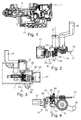
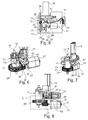
- the handle 1 of the invention is a motorized handle which enables the closing and opening of a vehicle door (not shown).
- the said handle comprises a grip member 3 configured to cooperate with a latch mechanism (not shown) so as to unlatch the door.
- the grip member 3 comprises a gripping part 5 which is intended to be gripped by the user hand.
- the grip member 3 is movable between:
- the handle 1 of the invention also comprises a driving mechanism 11 moving in rotation according to a driving rotation axis 13 and intended to drive an actuator lever 15 cooperating with the grip member 3 for driving the grip member 3 between the flushing position and the active position.
- the actuator lever 15 may be driven in rotation or in translation by the driving mechanism 11.
- the driving mechanism 11 may be a part of the actuator lever 15 forming an element or may be distinct of the actuator lever 15, as shown in the figures.
- the actuator lever 15 may be movable in translation or in rotation as shown in the embodiments of the figures.
- the actuator lever is movable in rotation, the latter comprises a lever rotation axis 14.
- the movement of the handle 1 of the invention for the opening or the closing may be achieved by a direct contact with a rotational moving part of the actuator lever 15, as shown in the figures.
- the movement of the handle 1 of the invention for the opening or closing may be achieved by a direct contact with a translational moving part of an actuator lever.
- the movement of the handle 1 of the invention for the opening or closing may be achieved by a direct contact with rotational moving part acting like a lever which could be driven by a translational actuator lever.
- the driving mechanism 11 may also comprise at least one brake system (not shown) for adapting the speed of the actuator lever 15.
- brake system may be a mechanical friction based brake, a magnetically brake without power supply or a electro-magnetically brake with external power supply.
- the handle 1 of the invention further comprises a motor 21 cooperating with the driving mechanism 11 for moving the said driving mechanism 11 according to the driving rotation axis 13.
- the output shaft 22 of the motor 21 may have a motor rotation axis 23 sensibly perpendicular to the driving rotation axis 13 which enables to reduce space.
- the driving rotation axis 13 is sensibly perpendicular to the lever rotation axis. In such embodiment and the driving rotation axis 13 is also sensibly perpendicular to output shaft 22 of the motor 21. Such configuration enables to reduce the space of the handle of the invention.
- the driving rotation axis 13 is sensibly parallel and apart from the lever rotation axis and the driving rotation axis 13 is also sensibly perpendicular to output shaft 22 of the motor 21 which is then perpendicular to the lever rotation axis 14.
- the output shaft 22 of the motor may be connected to a worm 24, such as a worm wheel, which rotates a first intermediate gear 25 with a bigger diameter.
- a worm 24 such as a worm wheel
- Such gear 25 may rotate a wheel shaft 26 which rotate a second intermediate gear 27 with a smaller diameter which rotates the driving mechanism 11, via for example a first end driving gear 28.
- the gear assembly comprising all the gears 24, 25, 27 and 28 involved in the connection between the motor movement and the driving mechanism movement may be reversible or not. The reversibility is possible via an appropriate friction between all the gears 24, 25, 27 and 28.
- the gear assembly may be designed as to be non reversible, for example with a proper choice of the helix angle of the worm 24 and the first intermediate gear 25.
- the driving mechanism 11 comprises a clutch system 71 because the cinematic of the gears is not reversible.
- the said clutch 71 is needed in a functional point of view.
- the clutch system 71 may be a mechanical clutch, such as a wrap-spring based concept, or an electro-magnetically clutch.
- the second end driving gear of the gear assembly opposite to the first end driving gear may be connected to the said clutch system 71.
- the driving mechanism 11 may then comprise a driving output lever 73 with a specific shape like a cam profile on one end, in order to directly or indirectly drive the gripping part 5 during the opening or closing movement of the handle 1 of the invention.
- the driving output lever 73 is then rotated in one direction for the opening of the handle 1 of the invention and in the reverse direction for the closing of the handle 1 of the invention.
- the change in the direction of rotation of the driving output lever 73 is achieved in changing the rotation direction of the motor 21.
- the change of rotation of the motor 21 may be done by reversing the power supply.
- the clutch system 71 may be designed in order to engage the connection between the gear assembly and the driving output lever 73 when the torque is coming from the motor 21 or the gear assembly stage side whatever the actuation direction is.
- the clutch system 71 may be disengaged when the torque or force is coming from the output side, for example, from the handle 1 itself or from another mechanical system used for opening or closing in case of loss of battery whatever the direction is.
- the output lever 73 When declutched, the output lever 73 may be freely rotated, for example by the handle 1 of the invention, independently from the gear assembly or the motor 21, which stays in the same position.
- the gear assembly may be designed to be reversible within a defined range of force or torque. No clutch is needed due to the reversibility.
- the handle may be maneuver by the user directly through the grip member in a reverse way.
- the second end driving gear may be directly connected to the driving output lever 73.
- the driving output lever 73 then comprises a specific shape, like a cam profile on its other end, in order to directly or indirectly drive the handle 1 of the invention during the opening or closing movement.
- the driving output lever 73 is then rotated in one direction for opening of the handle 1 of the invention and in the reverse direction for the closing of the handle 1 of the invention.
- the change in the direction of rotation of the driving output lever 73 is achieved in changing the rotation direction of the motor 21, by reversing the power supply for example.
- the inner friction inside the gear chain from the driving output lever 73 to the motor 21 is high enough to support the closing force applied by the handle, specifically any main spring insuring a stable position of the handle 1 of the invention.
- This inner friction may be chosen in order to be low enough to allow manual movement of the handle 1 of the invention by the user directly or through the activation of a mechanical function acting when no energy is powered to the motor 21.
- the handle 1 of the invention is then designed to respect this given functional friction range over the whole temperature range. This may be done with the proper geometry of the gears 24, 25, 27 and 28 and with the proper material combination including the choice of a lubrication matter.
- a supplementary brake may even be used in the kinematic chain in order to add supplementary friction and reach a predetermined target balance between minimum and maximum friction values required for the function of the reversible handle 1 of the invention.
- the handle 1 further comprises a position determining assembly 31, specifically an absolute position determining assembly, for determining the rotation position of the driving mechanism 11 while the said driving mechanism 11 is rotating.
- the position determining assembly 31 is capable of detecting the angular position of the actuator lever 15 at any time and then the gripping part 5. This is advantageously activated even when the loading torque is coming whether from the motor 21 or the driving mechanism 11 and whatever the rotation direction of the gripping part 5 is.
- the flushing position of the handle 1 of the invention may be adjusted during the final assembly of the door sub-components at the automotive vehicle factory, in order to have an accurate flushing position of the handle 1 whatever the tolerances of the door panel and all the other assembled sub-components may be. In that way, each handle 1 of the invention has one specific programmed flushing position.
- the position determining assembly 31 enables to have access to the change in the position, the direction and/or the speed of the handle 1 of the invention.
- This information given to the unit control of the handle 1 enables the control of the movement of the actuator lever 15 to perform an action according to the user wish.
- the position determining assembly 31 may be advantageously directly connected to the driving mechanism 11 which gives a better time response.
- the position determining assembly 31 may detect directly or indirectly a rotational movement or a linear movement of the actuator lever 15 in contact with the gripping part 5.
- the position determining assembly 31 may be an incremental sensor system.
- the position determining assembly 31 may comprise a magnet 33 rotated by the driving mechanism 11 according to a magnet rotation axis 35 and a Hall effect position sensor 37, specifically an absolute position sensor.
- the combination of the magnet 33 and the Hall effect position sensor 37 enables to detect directly the position, the direction and the speed of rotation of the driving mechanism 11. Indeed, each time the magnet 33 rotates, the Hall effect position sensor 37 detects the angular change in the position of the magnet 33 at any time. It is then possible to detect the direction of the rotation and the time of the change which induces the speed of rotation.
- the said magnet 33 may have a sensibly plane shape, for example a disc type shape, which gives more compactness.
- the magnet 33 may comprise one or several blades 39 to enable the said magnet 33 to closely follow the rotation of the driving mechanism 11 and then improve the accuracy of the position determining assembly.
- the magnet 33 may be advantageously rotated by a sensor gear wheel 41 rotated by the driving mechanism 11. This enables to have a simply and non costly drive means of the magnet 33.
- the sensor gear wheel 41 may cooperate with one or an assembly of driving wheels 43 following the rotation of the driving mechanism 11 which enables to have a good movement transmission.
- the sensor gear wheel 41 may be a part of the assembly of driving wheels 43.
- the sensor gear wheel 41 is implied in the rotation cinematic of the driving mechanism 11.
- the sensor gear wheel 41 may cooperate with a wheel 28 disposed close to the output shaft 22 of the motor 11 which enables to have a better precision of the angular position of the magnet 33.
- the sensor gear wheel 41 is then disposed so as to determine directly the rotation of the driving mechanism 11.
- the sensor gear wheel 41 may cooperate with a wheel 30 disposed close to the lever rotation axis 14.
- the reduction or increase ratio at sensor gear wheel 41 stage may be defined in order to have the best accuracy of the absolute position sensor in adjusting the rotation of the magnet 33 at around 300° for the complete movement.
- the magnet rotation axis 34 may be sensibly parallel to the driving rotation axis 13. This configuration enables to improve the compactness of the handle 1 of the invention.
- the handle 1 of the invention may also comprise a control unit (not shown) for controlling the motor 21 as well the position determining assembly 31. More specifically, the control unit is able to adjust the speed to get the smooth and simultaneous opening / closing of the handle 1 of the invention.
- control unit may be connected to the handle 1 of the invention through an external connector 51.
- the unit control then acquires directly the data collected by the position determining assembly 31 and then the data relative to the accurate position of the actuator lever 15 and the gripping part 5 at any time, during the opening or closing movement of the handle 1 of the invention or even when the actuator lever 15 is not in operation.
- the position of the handle 1 of the invention is available after battery replacement without any calibration cycle to be performed by the unit control. This enables to reduce time and costs.
- the Hall effect position sensor 37 may be placed on a printed circuit board 53 disposed in a plane sensibly parallel to the plan in which the magnet 33 is placed, the said printed circuit board 53 being connected to the control unit . Such configuration enables to transmit quickly without deficiency the data collected by the sensor 37.
- the control unit may advantageously be also connected to the driving mechanism 11 and be able to adapt the position and/or the speed of the said driving mechanism 11. Therefore, in a simple way, the movement of the driving mechanism 11 may be adapted depending on the data collected by the sensor 37.
- the driving mechanism 11 and the actuator lever 31 may advantageously be power supplied by the unit control instead of conventional constant voltage power supply.
- the power supply may therefore be adjusted in a way to compensate the tolerance dispersion of the single parts and tolerances resulting from changing temperature conditions or battery voltage and wear of single components. This adjustment then allows ensuring a constant opening or closing time between all vehicle doors and over life time of the vehicle. This may be achieved with combination of control loops at the unit control level to reach a pre-defined target position and / or speed profile.
- the tolerance range of the timing for opening and closing of the handle 1 of the invention is therefore drastically reduced. This feature allows as well ensuring a simultaneous movement of all handles of the vehicle, giving a fine quality impression to the user.
- This kind of power control enables to keep a low and constant rotation speed of the motor 21, whatever the battery voltage, which will then lead to low noise level and the absence of modulation during operation of the actuator lever 15. These factors account for the noise quality and for the global quality impression of the vehicle.
Landscapes
- Lock And Its Accessories (AREA)
Priority Applications (6)
| Application Number | Priority Date | Filing Date | Title |
|---|---|---|---|
| EP16173447.0A EP3255231A1 (de) | 2016-06-08 | 2016-06-08 | Handgriff für eine fahrzeugtür |
| CN201780029927.XA CN109219683B (zh) | 2016-06-08 | 2017-06-07 | 用于车门的把手 |
| EP17727615.1A EP3469176A1 (de) | 2016-06-08 | 2017-06-07 | Handgriff für eine fahrzeugtür |
| PCT/EP2017/063848 WO2017211891A1 (en) | 2016-06-08 | 2017-06-07 | Handle for a vehicle door |
| JP2018564361A JP6975180B2 (ja) | 2016-06-08 | 2017-06-07 | 車両ドア用ハンドル |
| US16/214,441 US20190112846A1 (en) | 2016-06-08 | 2018-12-10 | Handle for a vehicle door |
Applications Claiming Priority (1)
| Application Number | Priority Date | Filing Date | Title |
|---|---|---|---|
| EP16173447.0A EP3255231A1 (de) | 2016-06-08 | 2016-06-08 | Handgriff für eine fahrzeugtür |
Publications (1)
| Publication Number | Publication Date |
|---|---|
| EP3255231A1 true EP3255231A1 (de) | 2017-12-13 |
Family
ID=56119353
Family Applications (2)
| Application Number | Title | Priority Date | Filing Date |
|---|---|---|---|
| EP16173447.0A Withdrawn EP3255231A1 (de) | 2016-06-08 | 2016-06-08 | Handgriff für eine fahrzeugtür |
| EP17727615.1A Pending EP3469176A1 (de) | 2016-06-08 | 2017-06-07 | Handgriff für eine fahrzeugtür |
Family Applications After (1)
| Application Number | Title | Priority Date | Filing Date |
|---|---|---|---|
| EP17727615.1A Pending EP3469176A1 (de) | 2016-06-08 | 2017-06-07 | Handgriff für eine fahrzeugtür |
Country Status (5)
| Country | Link |
|---|---|
| US (1) | US20190112846A1 (de) |
| EP (2) | EP3255231A1 (de) |
| JP (1) | JP6975180B2 (de) |
| CN (1) | CN109219683B (de) |
| WO (1) | WO2017211891A1 (de) |
Cited By (6)
| Publication number | Priority date | Publication date | Assignee | Title |
|---|---|---|---|---|
| EP3498953A1 (de) * | 2017-12-14 | 2019-06-19 | U-Shin Deutschland Zugangssysteme GmbH | Fahrzeugtürgriffanordnung |
| FR3078991A1 (fr) | 2018-03-16 | 2019-09-20 | Mgi Coutier Espana | Commande d’ouverture à actionneur linéaire pour véhicule automobile. |
| WO2019219954A1 (fr) * | 2018-05-18 | 2019-11-21 | U-Shin Italia S.P.A. | Dispositif de poignée de porte automobile à connectique optimisée |
| US11066857B2 (en) * | 2017-01-27 | 2021-07-20 | Huf Hülsbeck & Fürst Gmbh & Co. Kg | Motor vehicle handle |
| US11519204B2 (en) | 2018-03-16 | 2022-12-06 | Akwel Vigo Spain Sl | Opening control with a linear actuator for a motor vehicle |
| US11607932B2 (en) | 2018-03-21 | 2023-03-21 | Akwel Vigo Spain Sl | Opening control device with emergency mechanical unlocking |
Families Citing this family (3)
| Publication number | Priority date | Publication date | Assignee | Title |
|---|---|---|---|---|
| CN112814503A (zh) * | 2019-11-15 | 2021-05-18 | 伊利诺斯工具制品有限公司 | 执行器 |
| JP2022118865A (ja) * | 2021-02-03 | 2022-08-16 | マツダ株式会社 | 車両のドアハンドル構造 |
| DE102022123131A1 (de) | 2022-09-12 | 2024-04-25 | Kiekert Aktiengesellschaft | Vorrichtung zum Antrieb eines Türgriffs |
Citations (4)
| Publication number | Priority date | Publication date | Assignee | Title |
|---|---|---|---|---|
| EP1099810A1 (de) * | 1999-11-10 | 2001-05-16 | Renault | Betätigungsvorrichtung für einen Verriegelungsmechanismus einer Fahrzeugtür |
| FR2889553A1 (fr) * | 2005-08-02 | 2007-02-09 | Renault Sas | Commande d'ouverture exterieure motorisee d'un ouvrant d'un vehicule automobile |
| US20140022811A1 (en) * | 2011-09-26 | 2014-01-23 | Tesla Motors, Inc. | Illumination apparatus for vehicles |
| WO2015148788A1 (en) * | 2014-03-26 | 2015-10-01 | Adac Plastics, Inc. | Handle assembly for a motor vehicle door |
Family Cites Families (6)
| Publication number | Priority date | Publication date | Assignee | Title |
|---|---|---|---|---|
| JP4300858B2 (ja) * | 2003-04-22 | 2009-07-22 | アイシン精機株式会社 | 車両ドア制御装置 |
| BE1016663A3 (nl) * | 2005-06-30 | 2007-04-03 | Vanderick Frans J R | Mechanisme voor het ontgrendelen van een deur. |
| US7621573B2 (en) * | 2007-08-08 | 2009-11-24 | Gm Global Technology Operations, Inc. | Flush vehicle door handle |
| FR2927431B1 (fr) * | 2008-02-07 | 2010-04-23 | Renault Sas | Dispositif de commande en ouverture d'un ouvrant de vehicule automobile. |
| GB2517348B (en) * | 2012-09-25 | 2015-09-23 | Jaguar Land Rover Ltd | Retractable handle arrangement |
| CN105464492B (zh) * | 2014-09-04 | 2018-03-30 | 上海汽车集团股份有限公司 | 车门把手系统 |
-
2016
- 2016-06-08 EP EP16173447.0A patent/EP3255231A1/de not_active Withdrawn
-
2017
- 2017-06-07 EP EP17727615.1A patent/EP3469176A1/de active Pending
- 2017-06-07 CN CN201780029927.XA patent/CN109219683B/zh active Active
- 2017-06-07 WO PCT/EP2017/063848 patent/WO2017211891A1/en active Search and Examination
- 2017-06-07 JP JP2018564361A patent/JP6975180B2/ja active Active
-
2018
- 2018-12-10 US US16/214,441 patent/US20190112846A1/en not_active Abandoned
Patent Citations (4)
| Publication number | Priority date | Publication date | Assignee | Title |
|---|---|---|---|---|
| EP1099810A1 (de) * | 1999-11-10 | 2001-05-16 | Renault | Betätigungsvorrichtung für einen Verriegelungsmechanismus einer Fahrzeugtür |
| FR2889553A1 (fr) * | 2005-08-02 | 2007-02-09 | Renault Sas | Commande d'ouverture exterieure motorisee d'un ouvrant d'un vehicule automobile |
| US20140022811A1 (en) * | 2011-09-26 | 2014-01-23 | Tesla Motors, Inc. | Illumination apparatus for vehicles |
| WO2015148788A1 (en) * | 2014-03-26 | 2015-10-01 | Adac Plastics, Inc. | Handle assembly for a motor vehicle door |
Cited By (13)
| Publication number | Priority date | Publication date | Assignee | Title |
|---|---|---|---|---|
| US11066857B2 (en) * | 2017-01-27 | 2021-07-20 | Huf Hülsbeck & Fürst Gmbh & Co. Kg | Motor vehicle handle |
| WO2019115734A1 (en) * | 2017-12-14 | 2019-06-20 | U-Shin Deutschland Zugangssysteme Gmbh | Vehicle door handle assembly |
| US11549288B2 (en) | 2017-12-14 | 2023-01-10 | U-Shin Deutschland Zugangssysteme Gmbh | Vehicle door handle assembly |
| EP3498953A1 (de) * | 2017-12-14 | 2019-06-19 | U-Shin Deutschland Zugangssysteme GmbH | Fahrzeugtürgriffanordnung |
| CN111527276B (zh) * | 2017-12-14 | 2021-12-07 | 有信德国接入系统有限责任公司 | 车门把手组件 |
| CN111527276A (zh) * | 2017-12-14 | 2020-08-11 | 有信德国接入系统有限责任公司 | 车门把手组件 |
| JP2021507143A (ja) * | 2017-12-14 | 2021-02-22 | ユーシン ドイチュラント ツーガングスジュステーメ ゲゼルシャフト ミット ベシュレンクテル ハフツング | 車両用ドアハンドルアセンブリ |
| US11519204B2 (en) | 2018-03-16 | 2022-12-06 | Akwel Vigo Spain Sl | Opening control with a linear actuator for a motor vehicle |
| FR3078991A1 (fr) | 2018-03-16 | 2019-09-20 | Mgi Coutier Espana | Commande d’ouverture à actionneur linéaire pour véhicule automobile. |
| US11679651B2 (en) | 2018-03-16 | 2023-06-20 | Akwel Vigo Spain S.L | Opening control device with a mechanical pop-out |
| US11607932B2 (en) | 2018-03-21 | 2023-03-21 | Akwel Vigo Spain Sl | Opening control device with emergency mechanical unlocking |
| FR3081179A1 (fr) * | 2018-05-18 | 2019-11-22 | U-Shin Italia S.P.A. | Dispositif de poignee de porte automobile a connectique optimisee |
| WO2019219954A1 (fr) * | 2018-05-18 | 2019-11-21 | U-Shin Italia S.P.A. | Dispositif de poignée de porte automobile à connectique optimisée |
Also Published As
| Publication number | Publication date |
|---|---|
| EP3469176A1 (de) | 2019-04-17 |
| CN109219683A (zh) | 2019-01-15 |
| CN109219683B (zh) | 2021-03-30 |
| JP2019518892A (ja) | 2019-07-04 |
| US20190112846A1 (en) | 2019-04-18 |
| WO2017211891A1 (en) | 2017-12-14 |
| JP6975180B2 (ja) | 2021-12-01 |
Similar Documents
| Publication | Publication Date | Title |
|---|---|---|
| EP3255231A1 (de) | Handgriff für eine fahrzeugtür | |
| JP5243018B2 (ja) | 電動リニアアクチュエータ | |
| US7382107B2 (en) | Shift range switching apparatus | |
| US11022218B2 (en) | Parking interlock in a vehicular transmission | |
| JP4226893B2 (ja) | アクチュエータ | |
| CN106321815B (zh) | 车辆变速驱动桥和驻车致动器组件 | |
| JP4063435B2 (ja) | 自動車 | |
| JP2013534396A (ja) | 自動車の開閉パネルのためのモータによる駆動装置 | |
| KR20050050571A (ko) | 쉬프트 바이 와이어 자동 변속장치 시스템용 액추에이터 | |
| US6270149B1 (en) | Slide door apparatus for vehicles | |
| JP2010159828A (ja) | 回転式アクチュエータおよびその製造方法 | |
| EP3324081B1 (de) | Stellglied für ein shift-by-wire-automatikgetriebe | |
| WO2009122810A1 (ja) | 車輌のレンジ切換え装置 | |
| EP2708329B1 (de) | Kraftgetriebenes Handwerkzeug | |
| JP2016080161A (ja) | 動力伝達機構 | |
| US11655895B2 (en) | Integrated park module systems and methods | |
| US6647814B2 (en) | Selective drive mechanism | |
| CN112984000B (zh) | 离合器致动器和用于控制离合器致动器的方法 | |
| JP2016102608A (ja) | 冷蔵庫用扉開閉機構 | |
| JP2007204982A (ja) | ドア駆動装置 | |
| CN112701847A (zh) | 致动器 | |
| JP2013019215A (ja) | 車両用ドアロック装置 | |
| JP6953638B2 (ja) | 自動車の変速機を制御するためのシフタ組立体 | |
| KR20220166530A (ko) | 자동차용 시프트 바이 와이어 파킹 액츄에이터 | |
| JP2006029209A (ja) | バルブリフト制御装置のアクチュエータ |
Legal Events
| Date | Code | Title | Description |
|---|---|---|---|
| PUAI | Public reference made under article 153(3) epc to a published international application that has entered the european phase |
Free format text: ORIGINAL CODE: 0009012 |
|
| AK | Designated contracting states |
Kind code of ref document: A1 Designated state(s): AL AT BE BG CH CY CZ DE DK EE ES FI FR GB GR HR HU IE IS IT LI LT LU LV MC MK MT NL NO PL PT RO RS SE SI SK SM TR |
|
| AX | Request for extension of the european patent |
Extension state: BA ME |
|
| STAA | Information on the status of an ep patent application or granted ep patent |
Free format text: STATUS: THE APPLICATION IS DEEMED TO BE WITHDRAWN |
|
| 18D | Application deemed to be withdrawn |
Effective date: 20180614 |