EP3251995B1 - Kabinenschutzeinrichtung für eine kabine einer aufzuganlage - Google Patents
Kabinenschutzeinrichtung für eine kabine einer aufzuganlage Download PDFInfo
- Publication number
- EP3251995B1 EP3251995B1 EP17174090.5A EP17174090A EP3251995B1 EP 3251995 B1 EP3251995 B1 EP 3251995B1 EP 17174090 A EP17174090 A EP 17174090A EP 3251995 B1 EP3251995 B1 EP 3251995B1
- Authority
- EP
- European Patent Office
- Prior art keywords
- cabin
- apron
- protection device
- trigger
- shaft bottom
- Prior art date
- Legal status (The legal status is an assumption and is not a legal conclusion. Google has not performed a legal analysis and makes no representation as to the accuracy of the status listed.)
- Not-in-force
Links
- 230000005540 biological transmission Effects 0.000 description 12
- 238000009434 installation Methods 0.000 description 11
- 230000006835 compression Effects 0.000 description 6
- 238000007906 compression Methods 0.000 description 6
- 230000033001 locomotion Effects 0.000 description 6
- 238000010008 shearing Methods 0.000 description 6
- 238000013459 approach Methods 0.000 description 5
- 238000012423 maintenance Methods 0.000 description 3
- 238000000034 method Methods 0.000 description 3
- 230000003993 interaction Effects 0.000 description 2
- 210000000323 shoulder joint Anatomy 0.000 description 2
- 230000007704 transition Effects 0.000 description 2
- 230000001419 dependent effect Effects 0.000 description 1
- 230000007257 malfunction Effects 0.000 description 1
Images


Classifications
-
- B—PERFORMING OPERATIONS; TRANSPORTING
- B66—HOISTING; LIFTING; HAULING
- B66B—ELEVATORS; ESCALATORS OR MOVING WALKWAYS
- B66B13/00—Doors, gates, or other apparatus controlling access to, or exit from, cages or lift well landings
- B66B13/24—Safety devices in passenger lifts, not otherwise provided for, for preventing trapping of passengers
- B66B13/28—Safety devices in passenger lifts, not otherwise provided for, for preventing trapping of passengers between car or cage and wells
- B66B13/285—Toe guards or apron devices
Definitions
- the invention relates to a cabin protection device for a cabin of an elevator installation. If a cabin of an elevator system stops at a floor of a building, the cabin floor and the floor of the floor should be flush so as to allow passengers to get out of the cabin as comfortably and safely as possible. However, if the car comes to a stop above the floor of the floor, a vertical opening is formed between the car floor and the floor of the floor and there is a risk of people falling into the elevator shaft. Further, for example, a fire that has broken out in a lower floor could roll over to the upper floor through the opening between the cabin floor and the floor of the storey.
- a cabin skirt below the cabin door which projects downwards in the vertical direction, ie in the direction of the shaft bottom, and thus closes the possible opening between the cabin floor and the floor of the storey.
- a cabin apron has for example a dimension of 2 m 2 .
- the elevator shaft or pit must be deep enough to accommodate the cabin apron when the cabin is at its lowest position.
- the possibilities for excavating a correspondingly deep shaft pit are not given or at least limited.
- a telescopic apron which consists for example of three telescoping panels in the vertical direction.
- WO 2013/054321 discloses a cabin protection device for a cabin of an elevator system, comprising at least one cabin apron which is pivotally connected to the car about a horizontal axis and extends in its folded position vertically downwards and in its Einklappposition obliquely or horizontally below the car floor, and a flap means, the a trigger bar, which is mounted with a horizontal distance to the horizontal axis and down to the shaft bottom extending so long that when the cabin apron is in its Ausklappposition and the shaft base just barely touched, with the trigger rod of the shaft base by moving the cabin in the direction of the shaft base is contactable, and at least one transmission that within the horizontal distance between the trigger bar and the cabin apron is arranged and these coupled to each other, so that when approaching the cabin to the shaft bottom of the trigger rod contacted this, by continuing to drive the cabin toward the shaft bottom of the shaft base via the trigger rod and the transmission of the cabin apron of the Ausklappposition can be brought into the folding position, whereby
- the object of the invention is to provide a car protection device for a cabin of an elevator installation, wherein the Elevator system is safe to operate and yet the shaft pit needs to be made only flat and the car protection device is low maintenance and reliable.
- the cabin protection device for a cabin of an elevator installation has at least one cabin apron, which is articulated on the cabin about a horizontal axis pivotally and in its folded position vertically downwards and in its Einklappposition obliquely or horizontally extending below the cabin floor, and a flap on the, a trigger bar, which is mounted on the cabin floor with a horizontal distance to the horizontal axis and extends from the cabin floor down to the shaft base down so long that when the cabin apron is in its Ausklappposition and the shaft bottom just does not touch, with the trigger rod of the shaft bottom by method the cab is contactable to the shaft bottom, and having at least one transmission which is disposed within the horizontal distance between the trigger rod and the cabin skirt and these coupled to each other, so that when approaching the cabin the manhole base of the release rod contacted this, by the onward travel of the cabin in the direction of the shaft bottom of the shaft base via the trigger rod and the gearbox the cabin apron from the Ausklappposition can be brought into the Ein
- the elevator system is intended for a building in which a corresponding elevator shaft is installed, in which the elevator system is housed.
- the elevator shaft extends from the basement of the building to its top floor, so that with the elevator system each floor of the building can be reached.
- the cabin in the elevator shaft move vertically, wherein the cabin can be stopped in each floor so that the cabin floor is flush with the respective floor floor.
- the cabin in one of the floors comes to a halt such that the cabin floor is arranged above this floor, an opening remains between the cabin floor and the floor of the floor, through which the elevator shaft is accessible from the floor.
- the fact that the cabin apron is in its Ausklappposition as soon as the trigger rod no longer contacts the shaft base, the opening is covered by the cabin apron.
- the cabin in the elevator shaft moves down to drive to the basement, the cabin approaches the shaft bottom.
- the cabin apron is moved from its folded-out position into its folded-in position when the cabin is moved further in the direction of the shaft bottom. Due to the fact that the release rod has a longer extension downwards than the cabin apron, a collision of the cabin apron with the shaft base is prevented. Otherwise, the pit would have to be made deeper, which would then provide sufficient space for the cabin apron in the Ausklappposition. Due to the cab protection device according to the invention, it is rather possible to perform the pit only flat, which is structurally advantageous.
- the car protection device is independently operable independently of any external power supply, whereby the car protection device is simple and reliable and only requires a low maintenance required.
- the cabin apron is in the folded position. This would not cover any opening between the cabin floor and the basement floor of the cabin apron. However, this is not critical, since the pit of the elevator shaft needs to be formed only flat anyway.
- the transmission preferably has a traction means which is fixed both to the trigger rod and to the cabin apron, whereby via the traction means the cabin apron of the trigger rod for bringing from the Ausklappposition in the Einklappposition is drivable.
- Preferred dimensions of the traction means is a rope or a tie rod.
- the traction cable is preferably guided around deflection rollers.
- the transmission comprises a gear fixed to the cab apron such that the horizontal axis about which the cab apron is pivotal coincides with the axis of rotation of the gear, the trigger bar having a serration integral with the gear Intervention is, whereby during a longitudinal movement of the trigger rod via the gear, the cabin apron can be brought from its folded position into its Ausklappposition.
- the transmission advantageously has few and functionally reliable components, whereby the maintenance of the car protection device is low.
- the folding protection device preferably has two cabin skirts facing one another and one of the traction means for each of the cabin aprons, wherein the trigger bar is arranged between the cabin skirts. If the cabin is to be accessible from two opposite sides from one floor, the two cabin skirts located opposite one another enable safe operation of the elevator installation. The fact that only a single release rod is provided for the two cabin aprons, the structure of the cabin protection device is simple and safe in operation.
- the folding protection device comprises a single cabin apron which is hinged to one side of the cabin, and the trigger bar is arranged on one side opposite the other side, wherein the traction means bridges the distance between the one side and the other side ,
- the trigger bar is preferably mounted displaceably on the cabin along its longitudinal direction. Furthermore, it is preferred that the cabin apron between its articulation on the cabin and the determination of the traction means is rigid. As a result, the cabin protection device according to the invention has a few moving parts, which merely have at least a slight wear.
- the cabin protection device preferably has a locking device with which the cabin apron can be locked in its folded-in position and / or in its folded-out position. This prevents that when the cabin apron covers an opening between the cabin floor and a storey floor, the cabin apron can be pressed into the elevator shaft approximately.
- the locking device preferably has a donor rod, which is arranged such that when approaching the car to the shaft bottom of the donor rod in front of the trigger rod contacted the manhole base, thereby unlocking the locking device is feasible.
- the operation of the donor rod is analogous to that of the trigger rod, wherein via the donor rod by the weight of the cab when driving down a force from the shaft base on the locking device for locking and / or unlocking the locking device is transferable.
- the latch means comprises biasing means coupled to the trigger bar, the trigger bar cooperating with the biasing means such that once the trigger bar contacts the shaft base as the car approaches the shaft base and a biasing force of the biasing means is overcome by the trigger bar Unlocking the locking device is feasible. As a result, about a donor rod for handling the locking device does not need to be provided and with the trigger rod both the pivoting of the cabin apron and the operation of the locking device are accomplished.
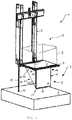
- an elevator installation 1 has an elevator shaft 2, the lower end of which is formed by a shaft pit 3.
- the bottom of the shaft pit 3 is the shaft bottom 4.
- a car 5 of the elevator installation 1 is arranged in the elevator shaft 2 for the vertical method.
- the car 5 further has a car door (not shown) through which the car 5 is accessible from outside about a floor into which the car 5 is driven.
- the car door is telescoping, so that a car door travel rail 7 is provided on the cabin floor 8 of the car 5 for the car door.
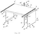
- the elevator installation 1 according to FIGS. 10 to 14 has two opposing car doors, so that correspondingly two Kabineneverfahrschienen 7, 7 'are provided.
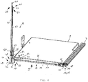
- the cabin protection device 9 has a cabin apron 10 which has a skirt 11.
- the cabin apron 10 is on the car traveling rail. 7 arranged, wherein the cabin skirt 10 in a fold-out position in which the apron sheet 11 from the Kabinentverschiene 7 extends vertically downwards, and in a Einklappposition can be brought, in which the apron sheet 11 extends horizontally from the Kabinentverschiene 7 below the cabin floor 8.
- FIGS. 1 to 4 and 8th the cabin apron is shown in its deployed position, whereas in FIG FIG. 6 the cabin apron 10 is shown in its folded position.
- the cabin apron 10 is shown in layers which are a transition from the fold-out position to the fold-in position.
- the cabin apron 10 has a skirt edge 12, which is a protruding from the apron sheet 11 profile, whereby the apron sheet 11 has a high rigidity.
- the apron sheet 11 has a Kröpflasche 14 on. With the help of Kröpflasche 14 a certain compressibility and / or foldability of the cabin apron 10 is achieved in a possible collision of the cabin apron 10 with the shaft base 4 or accidentally left on the shaft base 4 object.
- the apron proximal end 15 of the cabin apron 10 is disposed opposite the apron distal end 13 and immediately adjacent to the car door travel rail 7.
- the cabin skirt 10 has a Verschwenklager 16 as a linkage, which is formed by a bearing axis 17 and a bearing plate 18 in which a bearing hole 19 is made, through which the bearing axis 17 extends.
- the bearing axis 17 is arranged parallel to the car door travel rail 7 below the same.
- the bearing plate 18 is mounted below the car door travel rail 7, so that the cabin apron 10 is pivotally connected to the bearing plate 18 via the bearing shaft 17 on the car door travel rail 7.
- the axis line of the bearing axis 17 coincides with the horizontal axis about which the cabin skirt 10 is pivotable by means of Verschwenklagers 16.
- the car safety device 9 has a locking device 20 with which the car safety device 9 is held locked both in its folded-out position and in its folded-in position. During the transition of the car safety device 9 from the folded-out position into the folded-in position or vice versa, the car safety device 9 is unlocked so that a pivoting of the skirt sheet 11 about the bearing axis 17 is made possible. In contrast, in the locking of the locking device 20 pivoting of the skirt sheet 11 is inhibited about the bearing axis 17.
- the locking device 20 has an eccentric 21, which is attached to a longitudinal end of the bearing shaft 17 and thus eccentrically from the bearing shaft 17 is mitverformatbar.
- the eccentric 21 has a first locking surface 22 and a second locking surface 23 and a running surface 24, which is arranged in the circumferential direction of the eccentric 21 between the first locking surface 22 and the second locking surface 23.
- the first locking surface 22 and the second locking surface 23 have a radial course and limit in the circumferential direction of the tread 24 and thus the eccentric 21st
- the locking device 20 has a push rod 25 which is arranged longitudinally displaceable perpendicular to the bearing axis 17 on the cabin floor 8.
- the push rod 25 has a first push rod end 26 and a second push rod end 27, wherein the push rod ends 26, 27 facing away from each other and the first push rod end 26 is located on the eccentric 21.
- the push rod 25 has a push rod projection 28, which can be brought into engagement with the eccentric 21.
- the apron sheet 11 extends vertically from the cabin floor 8 down.
- the eccentric 21 is arranged such that its first locking surface 22 extends horizontally. In this position, the eccentric 21 and the push rod 25 are arranged relative to each other such that the push rod projection 28 above the first locking surface 22 abuts against this.
- the eccentric 21 presses with its first locking surface 22 to the push rod projection 28, whereby a pivoting of the skirt sheet 11 is prevented.
- a positive connection is formed by the push rod projection 28 and the eccentric 21, by means of which the locking of the car safety device 9 is accomplished in the folded-out position.
- the eccentric 21 is exposed and the cabin skirt 10 is pivotable about its bearing axis 17 from the folded-out position to the folded-in position.
- the cabin apron 10 is in a position between the Ausklappposition and the folding position, the eccentric 21 via the bearing shaft 17 is rotated accordingly, so that the tread 24 is arranged facing the push rod projection 28.
- a support plate 29 is provided which has a hole through which the push rod 25 extends.
- the push rod 25 is on a support stage 30, wherein between the support plate 29 and the support stage 30, a compression coil spring 31 is arranged around the push rod 25 and supported both on the support plate 29 and the support 30 such that with the compression coil spring 31, the push rod 25 is biased in the direction of the eccentric 21. Is the apron 11 in the position between the Ausklappposition and the Einklappposition the push rod projection 28 is pressed with the compression coil spring 31 on the tread 24.
- the second locking surface 23 is arranged horizontally above the push rod projection 28, wherein the push rod projection 28 is no longer in contact with the tread 24.
- the push rod 25 is longitudinally displaced by the bias of the compression coil spring 31 toward the eccentric 21, wherein the push rod projection 28 with the second locking surface 23 engages.
- the cabin apron 10 can be brought back from the folding position in the Ausklappposition, the push rod 25 is displaced away from the eccentric 21 along its longitudinal direction, so that the push rod projection 28 is no longer engaged with the eccentric 21 and thereby the eccentric for pivoting the Schürzenblatts 11 is exposed again.
- the locking device 20 has a length adjustment device 32 with which the position of the push rod projection 28 relative to the eccentric 21 is adjustable.
- the push rod 25 on a lever 33 which is pivotally mounted with a lever bearing 34 on the frame 6.
- the lever 33 is formed by two legs, between which the lever bearing 34 is arranged and which has a leg with its one longitudinal end a first Hebelanlenkung 35, on which an exposed lever roller 37 is mounted, and the other leg with a second Hebelanlenkung 36 is hinged to the second push rod end 27. If the lever roller 37 is pivoted about the lever bearing 34, the push rod 25 is brought into a longitudinal movement, wherein the circular motion of the lever roller 37 is translated by the lever 33 in a translational movement of the push rod 25.
- the locking device 20 has a donor rod 38 which is mounted vertically extending and longitudinally displaceable on the frame 6.
- the length of the donor rod 38 is dimensioned such that, when the cabin apron 10 is in its deployed position, the donor rod 38 projects beyond the crop pocket 14 of the apron sheet 11 downwardly.
- the encoder rod 38 has a top GeberstablCode 39 located at the top, which is formed chamfered and thereby has a lifting flank 40, and a lower second GeberstablFigsende 41, which is arranged facing the shaft base 4.
- the donor rod 38 is arranged on the frame 6 relative to the lever roller 37 such that when the donor rod 38 is displaced upwardly relative to the cabin floor 8, the first donor rod end 39 interacts with its lifting flank 40 with the lever roller 37, whereby the lever roller 37 of the encoder rod 38 is displaced and thereby pivoted about the lever bearing 34 so that the push rod 25 is moved away from the eccentric 21 by the lever 33. If the donor rod 38 moves downward, the lever roller 37 is held in position by the donor rod 38 until the first donor rod end 39 with its lifting flank 40 from the lift roller 37, whereby by the biasing force of the compression coil spring 31, the push rod 25 together with the Lever 33 and the lever roller 37 is returned to its original position.
- a plate 42 is mounted, with the underside of the shaft base 4 of the donor rod 38 is contacted and on its side facing away from the underside a driver stage 43 has.
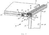
- the cabin protection device 9 has a flap 44.
- the flapper 44 has a trigger bar 45, the longitudinally displaceable vertically by a bearing sleeve 6 attached to the bearing sleeve extends.
- the release rod 45 is tubular, wherein the donor rod 38 is mounted longitudinally displaceable in the trigger rod 45 and from this, wherein the trigger rod 45 is mounted longitudinally displaceable by the bearing sleeve on the frame 6.
- the trigger rod 45 and the trigger rod 45 arranged internally in the donor rod 38 are arranged telescopically to each other.
- the donor rod 38 protrudes with its second GeberstablFigsende 41 and its plate 42 from the trigger rod 45 out.
- the trigger bar 45 has an overhead first trigger bar end 46 to which an eyelet 47 is attached. Further, the trigger bar 45 has a bottom second trigger bar end 48 which forms a follower stage 49.
- the second Geberstablnature 41 is dependent on the follower stage 49, wherein the plate 42 is arranged with its driver stage 43 facing the follower stage 49. If the cabin protection device 9 with its cabin apron 10 is in the folded-out position, then the second trigger bar end 48 is arranged with its follower step 49 below the crop pocket 14 of the apron sheet 11. If the car 5 approaches the shaft bottom 4, the plate 42 comes into contact with the shaft bottom 4.
- the transmitter rod 38 is displaced upward in the trigger rod 45 and relative to the car floor 8, the transmitter rod 38 with its lifting flank 40, the lever roller 37 pushes aside and thereby the push rod 25 is moved, whereby a release of the locking device 20 is accomplished.
- the follower stage 43 of the plate 42 contacts the follower stage 49 of the second longitudinal end 48.
- the release rod 45 with the transmitter rod 38 is displaced upward relative to the cabin floor 8.
- the trigger rod 45 has a dent 50 in the region of the second trigger rod end 48.
- the dimple 50 is arranged on the trigger bar 45 such that when the Cab apron 10 is in its Einklappposition, the lever roller 37 is engaged with the dent 50, whereby the lever roller 37 is pivoted about the lever bearing 34, wherein the push rod 25 is moved back toward the eccentric 21, which of the push rod projection 28 with the second locking surface 23 a positive locking of the control device 20 is accomplished.
- the flapper 44 has a gear 51.
- the transmission 51 has as a pulling means a rope 52 and three pulleys 53 to 55, wherein the rope 52 has a first end of the rope 56 and a second end 57 of the rope.
- the rope 52 With the first end of the rope 56, the rope 52 is attached to the freestanding longitudinal end of the apron flank 12 in the region of the Kröpflasche 14 and guided to the fixed to the cabin floor 8 first guide roller 53.
- the pulleys 54 and 55 are also attached to the cabin floor 8 and guide the rope 52 with its second end of the rope 57 to the eyelet 47 of the trigger rod 45, wherein the second cable end 57 is attached to the eyelet 47.
- the eyelet 47 is moved upwards relative to the car floor 8.
- the cabin apron 10 is pulled by the cable 52 via the deflection rollers 53 to 55 from the folded-out position into the folded-in position.
- the plate 42 contacts the shaft bottom 4 in a position in which the cabin apron 10 does not yet touch the shaft bottom 4 in the folded-out position.
- the cab 5 is moved upward as the cab 5 continues moving, whereby the push rod 25 is moved away from the eccentric 21 via the lever 33 by the interaction of the lifting flank 40 and the lever roller 37, so that the latch device 20 is unlocked .
- the driver stage 43 then contacts the follower stage 49, as a result of which the trigger rod 45 is displaced upward relative to the cabin floor 8.
- the trigger rod 45 pulls the eyelet 47th attached rope 52, whereby the cabin apron 10 is pivoted from the unfolded position to the folded position.
- the dent 50 With a correspondingly small distance of the cabin floor 8 from the shaft base 4, the dent 50 is brought into the position at the height of the lever roller 37, whereby the lever roller 37 engages in the dent 50, so that the push rod 25 is displaced toward the eccentric 21, whereby the locking device 20th is locked again.
- This position of the car 8 is the lowest position in the hoistway 2.
- the donor rod 38, together with the trigger bar 45 is moved downwardly relative to the cab floor 8, causing the lever roller 37 to disengage the dent 50, thereby unlocking the latch assembly 20.
- the trigger bar 45, together with the donor rod 38 is moved downwardly relative to the cabin floor 8, thereby increasing the cable length between the first diverting pulley 53 and the skirting end 13 and thereby the cab apron 10 from the folded position to the deployed position is brought.
- the movement of the trigger bar 45 ends relative to the cabin floor 8.
- the transmitter bar 38 is moved relative to the cabin floor 8 until the lifting flank 40 is lifted off the lever roller 37, whereby the locking device 20 locks the cabin apron 10 in its Ausklappposition.
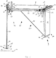
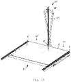
- FIGS. 10 to 14 shown second cabin aprons 10, 10 ', wherein the second cabin apron 10' a apron 11 ', a Schürzenflanke 12', a Schurzendistalende 13 ', a Kröpflasche 14' and a Schürzenproximalende 15 'analogous to the first cabin apron 10 has.
- the cabin skirts 10, 10 ' are arranged on two opposite sides of the car 5, with one of the car door travel rails 7, 7' attached to each of the sides.
- the trigger bar 45 is disposed between the cabin skirts 10, 10 'and is configured to operate both the one cabin apron 10 and the other cabin apron 10'.
- a shoulder bar 58 is fixed, which extends transversely to the release rod 45, whereby the trigger rod 45 together with the shoulder bar 58 have a T-shape.
- a shoulder joint 59 is provided, on each of which a pull rod 60, 60 'is articulated as a pulling means.
- the right pull rod 60 is coupled to the distal end 13 'of the left cabin skirt 10' by means of a skirt joint 61 ', whereas the left pull rod 60' is coupled to the distal end 13 of the right cabin skirt 10 by means of a skirt joint 61. Due to the T-shape of the trigger rod 45 and the shoulder beam 58 and the mutual assignment of the tie rods 60, 60 'to the cabin aprons 10', 10, the tie rods 60, 60 'crossed each other. As a result, the tie rods 60, 60 'arranged scissor-like.
- a guide sleeve 62 is mounted, with which the trigger rod 45 is mounted vertically displaceable.
- pins 63, 63 'for the locking device 20 are respectively attached to the left and right of the trigger rod 45.
- the locking device 20 is formed by a first shearing lever 64 and a two shear lever 65, which are fixed scissor-like via a shearing lever joint 66 together.
- the overhead longitudinal ends of the shear levers 64, 65 are coupled together with a tension coil spring 67 so that the overhead longitudinal ends of the shear arms 64, 65 are biased toward each other by a tensile force exerted by the tension coil spring 67.
- Tilting levers 68, 69 are articulated to the upper longitudinal ends of the shearing levers 64, 65, which are in turn pivotally mounted to each other at their longitudinal ends facing away from the shearing levers 64, 65 by means of a lever joint 70, wherein the lever joint 70 is attached to the first trigger rod end 46 of the trigger rod 45.
- the shear levers 64, 65 have at their longitudinal ends remote from the tension coil spring 67 each outer notches 71, 71 'which are engageable with the pins 63, 63' in engagement. At the notches 71, 71 'adjacent guide flanks 72, 72' form the lower longitudinal ends of the shear lever 64, 65th
- the first Auslöserstablteilsende 46 is arranged on the cabin floor 8 and on the guide sleeve 62, whereby the trigger rod 45 protrudes a maximum length of the cabin floor 8 down. If the car 5 is moved in the direction of the shaft bottom 4, touched in a corresponding position of the car 5 in the elevator shaft 2, the trigger rod 45 with its second Auslöserstablteilsende 48 the shaft bottom 4.
- the trigger rod 45 is moved relative to the cabin floor 8 shifted upward, whereby via the shoulder beam 58 and the tie rods 60, 60 'the cabin skirts 10, 10' inwardly below the cabin floor. 8 be folded. If the car 5 has reached its lowest point, then the cabin aprons 10, 10 'below the cabin floor 8 are folded substantially horizontally, wherein the trigger bar 45 protrudes maximum long up from the cabin floor 8. As it is in FIG. 14 is shown the cabin skirts 10, 10 'are slightly longer than half the embedding of the cabin floor 8 is formed. By a correspondingly different length of the tie rods 60, 60 ', a staggered folding of the cabin skirts 10, 10' can be accomplished, whereby a collision of the cabin skirts 10, 10 'is prevented in the folded position.
- the trigger rod 45 is displaced downwards relative to the cabin floor 8, as a result of which the cabin aprons 10, 10 'are again brought toward their deployed position.
- the shear levers 64, 65 approach the pivots 63, 63', with the guide flanks 72, 72 'touching the pivots 63, 63 from above when the cab 5 is in a corresponding position.
- the shear levers 64, 65 ' Upon further travel of the car 5 upwards, the shear levers 64, 65 'are pushed inward by the guide flanks 72, 72' at their lower longitudinal ends, overcoming the biasing force applied by the tension coil spring 67 until the notches 71, 71 'on the pins 63, 63 'engage. Then the cabin skirts 10, 10 'brought back into its Ausklappposition, wherein the locking device 20 is brought into its locked state by the engagement of the notches 71, 71' on the pin 63, 63 '. When the car 5 continues to move upwards, the cabin aprons 10, 10 'remain in their folded-out position, as a result of which the safety function of the car safety device 9 is achieved.
- the tension coil spring 67 acts as a support. Without the tension coil spring 67, the functioning of the locking device 20 is also achieved.
Landscapes
- Elevator Door Apparatuses (AREA)
- Cage And Drive Apparatuses For Elevators (AREA)
Priority Applications (1)
| Application Number | Priority Date | Filing Date | Title |
|---|---|---|---|
| PL17174090T PL3251995T3 (pl) | 2016-06-02 | 2017-06-01 | Urządzenie ochronne dla kabiny instalacji dźwigowej |
Applications Claiming Priority (1)
| Application Number | Priority Date | Filing Date | Title |
|---|---|---|---|
| DE102016110249.0A DE102016110249A1 (de) | 2016-06-02 | 2016-06-02 | Kabinenschutzeinrichtung für eine Kabine einer Aufzuganlage |
Publications (2)
| Publication Number | Publication Date |
|---|---|
| EP3251995A1 EP3251995A1 (de) | 2017-12-06 |
| EP3251995B1 true EP3251995B1 (de) | 2018-12-26 |
Family
ID=59009543
Family Applications (1)
| Application Number | Title | Priority Date | Filing Date |
|---|---|---|---|
| EP17174090.5A Not-in-force EP3251995B1 (de) | 2016-06-02 | 2017-06-01 | Kabinenschutzeinrichtung für eine kabine einer aufzuganlage |
Country Status (4)
| Country | Link |
|---|---|
| EP (1) | EP3251995B1 (pl) |
| DE (1) | DE102016110249A1 (pl) |
| ES (1) | ES2715970T3 (pl) |
| PL (1) | PL3251995T3 (pl) |
Families Citing this family (3)
| Publication number | Priority date | Publication date | Assignee | Title |
|---|---|---|---|---|
| ES2912314T3 (es) * | 2018-08-10 | 2022-05-25 | Otis Elevator Co | Faldón de cabina de ascensor |
| CN114450245A (zh) * | 2019-09-30 | 2022-05-06 | 因温特奥股份公司 | 电梯设备 |
| CN114516575B (zh) * | 2022-02-11 | 2023-11-07 | 内蒙古大唐国际托克托发电有限责任公司 | 一种无动力安全自锁系统 |
Family Cites Families (4)
| Publication number | Priority date | Publication date | Assignee | Title |
|---|---|---|---|---|
| IT251255Y1 (it) * | 2000-07-28 | 2003-11-19 | Selcom Spa | Paramento mobile in cabina di ascensore od elevatore |
| DE102008038409B4 (de) * | 2007-08-28 | 2016-12-22 | Thoma Aufzüge Gmbh | Vorrichtung zur Sicherung von Schachtzugängen von Aufzugsanlagen |
| ES2597969T3 (es) * | 2011-04-05 | 2017-01-24 | Otis Elevator Company | Conjunto de protección de los dedos de los pies para un sistema elevador |
| IL215654A (en) * | 2011-10-10 | 2015-01-29 | Yoram Madar | Folding apron for elevator with moving floor in pit with reduced depth |
-
2016
- 2016-06-02 DE DE102016110249.0A patent/DE102016110249A1/de not_active Withdrawn
-
2017
- 2017-06-01 EP EP17174090.5A patent/EP3251995B1/de not_active Not-in-force
- 2017-06-01 ES ES17174090T patent/ES2715970T3/es active Active
- 2017-06-01 PL PL17174090T patent/PL3251995T3/pl unknown
Non-Patent Citations (1)
| Title |
|---|
| None * |
Also Published As
| Publication number | Publication date |
|---|---|
| ES2715970T3 (es) | 2019-06-07 |
| EP3251995A1 (de) | 2017-12-06 |
| DE102016110249A1 (de) | 2017-12-07 |
| PL3251995T3 (pl) | 2019-07-31 |
Similar Documents
| Publication | Publication Date | Title |
|---|---|---|
| EP1772414B1 (de) | Faltbare selbsthemmende Fahrkorbschürze | |
| EP2243742B1 (de) | Scherenhebebühne | |
| EP1497217B1 (de) | Vorrichtung zur betätigung und verriegelung von aufzugstüren mit mitnehmerkufen | |
| DE69926244T2 (de) | Schachtsicherheitssystem für Aufzug | |
| EP2287104B1 (de) | Türkuppler und Verriegelungsmechanismus | |
| EP3251995B1 (de) | Kabinenschutzeinrichtung für eine kabine einer aufzuganlage | |
| AT413529B (de) | Vorrichtung zur betätigung und verriegelung von aufzugstüren | |
| EP1541518B1 (de) | Aufzugs-Türantriebsvorrichtung | |
| EP2185457B1 (de) | Aufzugskabinentür, die zum öffnen der kabine wahlweise nach oben oder nach unten über ihre gesamte vertikale länge beweglich ist | |
| EP1760026B1 (de) | Verfahren zur Durchführung von Wartungs- und Inspektionsarbeiten an einer Aufzugsanlage | |
| EP1826342B1 (de) | Sektionaltor mit Fluchttür | |
| DE10065101A1 (de) | Aufzug mit einer Schutzvorrichtung | |
| DE102006002184B4 (de) | Verfahren zum motorischen Anheben eines Scherenpodestes und Scherenpodest | |
| EP2836454B1 (de) | Verfahren zur positionierung von gegenmitnahmemitteln einer schachttür einer aufzuganlage | |
| EP3538410B1 (de) | Schienenfahrzeug mit innenraumabschnitten auf verschiedenen fussbodenhöhen | |
| EP1726560B1 (de) | Scherenhubtisch | |
| DE3543214C2 (pl) | ||
| EP3666719A1 (de) | Automatische abrollsicherung | |
| EP2050703B1 (de) | Aufzuganlage für Personen und/oder Lasten mit zumindest einer Aufzugkabine | |
| EP3152378B1 (de) | Schiebetür | |
| DE102012104987A1 (de) | Außentritt für den Führerstand von Schienenfahrzeugen | |
| EP4267815B1 (de) | Schienengeführtes klettersystem | |
| DE20202775U1 (de) | Aufzug mit einem temporären Schutzraum | |
| EP2072449B1 (de) | Türantriebsvorrichtung für Aufzugsanlagen | |
| DE2106983A1 (de) | Teleskopierbarer Kranausleger |
Legal Events
| Date | Code | Title | Description |
|---|---|---|---|
| PUAI | Public reference made under article 153(3) epc to a published international application that has entered the european phase |
Free format text: ORIGINAL CODE: 0009012 |
|
| STAA | Information on the status of an ep patent application or granted ep patent |
Free format text: STATUS: THE APPLICATION HAS BEEN PUBLISHED |
|
| STAA | Information on the status of an ep patent application or granted ep patent |
Free format text: STATUS: REQUEST FOR EXAMINATION WAS MADE |
|
| AK | Designated contracting states |
Kind code of ref document: A1 Designated state(s): AL AT BE BG CH CY CZ DE DK EE ES FI FR GB GR HR HU IE IS IT LI LT LU LV MC MK MT NL NO PL PT RO RS SE SI SK SM TR |
|
| AX | Request for extension of the european patent |
Extension state: BA ME |
|
| 17P | Request for examination filed |
Effective date: 20171116 |
|
| RBV | Designated contracting states (corrected) |
Designated state(s): AL AT BE BG CH CY CZ DE DK EE ES FI FR GB GR HR HU IE IS IT LI LT LU LV MC MK MT NL NO PL PT RO RS SE SI SK SM TR |
|
| GRAP | Despatch of communication of intention to grant a patent |
Free format text: ORIGINAL CODE: EPIDOSNIGR1 |
|
| STAA | Information on the status of an ep patent application or granted ep patent |
Free format text: STATUS: GRANT OF PATENT IS INTENDED |
|
| INTG | Intention to grant announced |
Effective date: 20180618 |
|
| GRAS | Grant fee paid |
Free format text: ORIGINAL CODE: EPIDOSNIGR3 |
|
| GRAJ | Information related to disapproval of communication of intention to grant by the applicant or resumption of examination proceedings by the epo deleted |
Free format text: ORIGINAL CODE: EPIDOSDIGR1 |
|
| GRAL | Information related to payment of fee for publishing/printing deleted |
Free format text: ORIGINAL CODE: EPIDOSDIGR3 |
|
| STAA | Information on the status of an ep patent application or granted ep patent |
Free format text: STATUS: REQUEST FOR EXAMINATION WAS MADE |
|
| GRAP | Despatch of communication of intention to grant a patent |
Free format text: ORIGINAL CODE: EPIDOSNIGR1 |
|
| STAA | Information on the status of an ep patent application or granted ep patent |
Free format text: STATUS: GRANT OF PATENT IS INTENDED |
|
| INTC | Intention to grant announced (deleted) | ||
| GRAA | (expected) grant |
Free format text: ORIGINAL CODE: 0009210 |
|
| STAA | Information on the status of an ep patent application or granted ep patent |
Free format text: STATUS: THE PATENT HAS BEEN GRANTED |
|
| INTG | Intention to grant announced |
Effective date: 20181029 |
|
| AK | Designated contracting states |
Kind code of ref document: B1 Designated state(s): AL AT BE BG CH CY CZ DE DK EE ES FI FR GB GR HR HU IE IS IT LI LT LU LV MC MK MT NL NO PL PT RO RS SE SI SK SM TR |
|
| REG | Reference to a national code |
Ref country code: GB Ref legal event code: FG4D Free format text: NOT ENGLISH |
|
| REG | Reference to a national code |
Ref country code: CH Ref legal event code: EP |
|
| REG | Reference to a national code |
Ref country code: AT Ref legal event code: REF Ref document number: 1081126 Country of ref document: AT Kind code of ref document: T Effective date: 20190115 |
|
| REG | Reference to a national code |
Ref country code: DE Ref legal event code: R096 Ref document number: 502017000562 Country of ref document: DE |
|
| REG | Reference to a national code |
Ref country code: IE Ref legal event code: FG4D Free format text: LANGUAGE OF EP DOCUMENT: GERMAN |
|
| REG | Reference to a national code |
Ref country code: CH Ref legal event code: NV Representative=s name: BRAUNPAT BRAUN EDER AG, CH |
|
| REG | Reference to a national code |
Ref country code: SE Ref legal event code: TRGR |
|
| REG | Reference to a national code |
Ref country code: NL Ref legal event code: FP |
|
| PG25 | Lapsed in a contracting state [announced via postgrant information from national office to epo] |
Ref country code: LT Free format text: LAPSE BECAUSE OF FAILURE TO SUBMIT A TRANSLATION OF THE DESCRIPTION OR TO PAY THE FEE WITHIN THE PRESCRIBED TIME-LIMIT Effective date: 20181226 Ref country code: HR Free format text: LAPSE BECAUSE OF FAILURE TO SUBMIT A TRANSLATION OF THE DESCRIPTION OR TO PAY THE FEE WITHIN THE PRESCRIBED TIME-LIMIT Effective date: 20181226 Ref country code: BG Free format text: LAPSE BECAUSE OF FAILURE TO SUBMIT A TRANSLATION OF THE DESCRIPTION OR TO PAY THE FEE WITHIN THE PRESCRIBED TIME-LIMIT Effective date: 20190326 Ref country code: LV Free format text: LAPSE BECAUSE OF FAILURE TO SUBMIT A TRANSLATION OF THE DESCRIPTION OR TO PAY THE FEE WITHIN THE PRESCRIBED TIME-LIMIT Effective date: 20181226 |
|
| REG | Reference to a national code |
Ref country code: LT Ref legal event code: MG4D |
|
| PG25 | Lapsed in a contracting state [announced via postgrant information from national office to epo] |
Ref country code: RS Free format text: LAPSE BECAUSE OF FAILURE TO SUBMIT A TRANSLATION OF THE DESCRIPTION OR TO PAY THE FEE WITHIN THE PRESCRIBED TIME-LIMIT Effective date: 20181226 Ref country code: AL Free format text: LAPSE BECAUSE OF FAILURE TO SUBMIT A TRANSLATION OF THE DESCRIPTION OR TO PAY THE FEE WITHIN THE PRESCRIBED TIME-LIMIT Effective date: 20181226 |
|
| REG | Reference to a national code |
Ref country code: GR Ref legal event code: EP Ref document number: 20190400878 Country of ref document: GR Effective date: 20190524 Ref country code: ES Ref legal event code: FG2A Ref document number: 2715970 Country of ref document: ES Kind code of ref document: T3 Effective date: 20190607 |
|
| REG | Reference to a national code |
Ref country code: NO Ref legal event code: T2 Effective date: 20181226 |
|
| PG25 | Lapsed in a contracting state [announced via postgrant information from national office to epo] |
Ref country code: PT Free format text: LAPSE BECAUSE OF FAILURE TO SUBMIT A TRANSLATION OF THE DESCRIPTION OR TO PAY THE FEE WITHIN THE PRESCRIBED TIME-LIMIT Effective date: 20190426 Ref country code: CZ Free format text: LAPSE BECAUSE OF FAILURE TO SUBMIT A TRANSLATION OF THE DESCRIPTION OR TO PAY THE FEE WITHIN THE PRESCRIBED TIME-LIMIT Effective date: 20181226 |
|
| PGFP | Annual fee paid to national office [announced via postgrant information from national office to epo] |
Ref country code: PT Payment date: 20190327 Year of fee payment: 3 Ref country code: PL Payment date: 20190530 Year of fee payment: 3 Ref country code: FI Payment date: 20190618 Year of fee payment: 3 |
|
| PG25 | Lapsed in a contracting state [announced via postgrant information from national office to epo] |
Ref country code: EE Free format text: LAPSE BECAUSE OF FAILURE TO SUBMIT A TRANSLATION OF THE DESCRIPTION OR TO PAY THE FEE WITHIN THE PRESCRIBED TIME-LIMIT Effective date: 20181226 Ref country code: SM Free format text: LAPSE BECAUSE OF FAILURE TO SUBMIT A TRANSLATION OF THE DESCRIPTION OR TO PAY THE FEE WITHIN THE PRESCRIBED TIME-LIMIT Effective date: 20181226 Ref country code: RO Free format text: LAPSE BECAUSE OF FAILURE TO SUBMIT A TRANSLATION OF THE DESCRIPTION OR TO PAY THE FEE WITHIN THE PRESCRIBED TIME-LIMIT Effective date: 20181226 Ref country code: IS Free format text: LAPSE BECAUSE OF FAILURE TO SUBMIT A TRANSLATION OF THE DESCRIPTION OR TO PAY THE FEE WITHIN THE PRESCRIBED TIME-LIMIT Effective date: 20190426 Ref country code: SK Free format text: LAPSE BECAUSE OF FAILURE TO SUBMIT A TRANSLATION OF THE DESCRIPTION OR TO PAY THE FEE WITHIN THE PRESCRIBED TIME-LIMIT Effective date: 20181226 |
|
| PGFP | Annual fee paid to national office [announced via postgrant information from national office to epo] |
Ref country code: FR Payment date: 20190626 Year of fee payment: 3 Ref country code: GR Payment date: 20190619 Year of fee payment: 3 Ref country code: SE Payment date: 20190624 Year of fee payment: 3 |
|
| REG | Reference to a national code |
Ref country code: DE Ref legal event code: R097 Ref document number: 502017000562 Country of ref document: DE |
|
| PG25 | Lapsed in a contracting state [announced via postgrant information from national office to epo] |
Ref country code: DK Free format text: LAPSE BECAUSE OF FAILURE TO SUBMIT A TRANSLATION OF THE DESCRIPTION OR TO PAY THE FEE WITHIN THE PRESCRIBED TIME-LIMIT Effective date: 20181226 |
|
| PGFP | Annual fee paid to national office [announced via postgrant information from national office to epo] |
Ref country code: ES Payment date: 20190723 Year of fee payment: 3 |
|
| PLBE | No opposition filed within time limit |
Free format text: ORIGINAL CODE: 0009261 |
|
| STAA | Information on the status of an ep patent application or granted ep patent |
Free format text: STATUS: NO OPPOSITION FILED WITHIN TIME LIMIT |
|
| 26N | No opposition filed |
Effective date: 20190927 |
|
| PG25 | Lapsed in a contracting state [announced via postgrant information from national office to epo] |
Ref country code: MC Free format text: LAPSE BECAUSE OF FAILURE TO SUBMIT A TRANSLATION OF THE DESCRIPTION OR TO PAY THE FEE WITHIN THE PRESCRIBED TIME-LIMIT Effective date: 20181226 |
|
| PG25 | Lapsed in a contracting state [announced via postgrant information from national office to epo] |
Ref country code: SI Free format text: LAPSE BECAUSE OF FAILURE TO SUBMIT A TRANSLATION OF THE DESCRIPTION OR TO PAY THE FEE WITHIN THE PRESCRIBED TIME-LIMIT Effective date: 20181226 |
|
| REG | Reference to a national code |
Ref country code: BE Ref legal event code: MM Effective date: 20190630 |
|
| PG25 | Lapsed in a contracting state [announced via postgrant information from national office to epo] |
Ref country code: TR Free format text: LAPSE BECAUSE OF FAILURE TO SUBMIT A TRANSLATION OF THE DESCRIPTION OR TO PAY THE FEE WITHIN THE PRESCRIBED TIME-LIMIT Effective date: 20181226 |
|
| PG25 | Lapsed in a contracting state [announced via postgrant information from national office to epo] |
Ref country code: IE Free format text: LAPSE BECAUSE OF NON-PAYMENT OF DUE FEES Effective date: 20190601 |
|
| REG | Reference to a national code |
Ref country code: DE Ref legal event code: R082 Ref document number: 502017000562 Country of ref document: DE Representative=s name: PATERIS THEOBALD ELBEL & PARTNER, PATENTANWAEL, DE Ref country code: DE Ref legal event code: R082 Ref document number: 502017000562 Country of ref document: DE Representative=s name: PATERIS THEOBALD ELBEL FISCHER, PATENTANWAELTE, DE Ref country code: DE Ref legal event code: R082 Ref document number: 502017000562 Country of ref document: DE Representative=s name: PATERIS PATENTANWAELTE, PARTMBB, DE |
|
| PG25 | Lapsed in a contracting state [announced via postgrant information from national office to epo] |
Ref country code: BE Free format text: LAPSE BECAUSE OF NON-PAYMENT OF DUE FEES Effective date: 20190630 Ref country code: LU Free format text: LAPSE BECAUSE OF NON-PAYMENT OF DUE FEES Effective date: 20190601 |
|
| PGFP | Annual fee paid to national office [announced via postgrant information from national office to epo] |
Ref country code: IT Payment date: 20200630 Year of fee payment: 4 |
|
| REG | Reference to a national code |
Ref country code: FI Ref legal event code: MAE |
|
| REG | Reference to a national code |
Ref country code: NO Ref legal event code: MMEP |
|
| PG25 | Lapsed in a contracting state [announced via postgrant information from national office to epo] |
Ref country code: FI Free format text: LAPSE BECAUSE OF NON-PAYMENT OF DUE FEES Effective date: 20200601 |
|
| REG | Reference to a national code |
Ref country code: CH Ref legal event code: PL |
|
| REG | Reference to a national code |
Ref country code: NL Ref legal event code: MM Effective date: 20200701 |
|
| PG25 | Lapsed in a contracting state [announced via postgrant information from national office to epo] |
Ref country code: FR Free format text: LAPSE BECAUSE OF NON-PAYMENT OF DUE FEES Effective date: 20200630 Ref country code: GR Free format text: LAPSE BECAUSE OF NON-PAYMENT OF DUE FEES Effective date: 20210111 Ref country code: CH Free format text: LAPSE BECAUSE OF NON-PAYMENT OF DUE FEES Effective date: 20200630 Ref country code: LI Free format text: LAPSE BECAUSE OF NON-PAYMENT OF DUE FEES Effective date: 20200630 Ref country code: NO Free format text: LAPSE BECAUSE OF NON-PAYMENT OF DUE FEES Effective date: 20200630 |
|
| PG25 | Lapsed in a contracting state [announced via postgrant information from national office to epo] |
Ref country code: CY Free format text: LAPSE BECAUSE OF FAILURE TO SUBMIT A TRANSLATION OF THE DESCRIPTION OR TO PAY THE FEE WITHIN THE PRESCRIBED TIME-LIMIT Effective date: 20181226 Ref country code: SE Free format text: LAPSE BECAUSE OF NON-PAYMENT OF DUE FEES Effective date: 20200602 |
|
| PG25 | Lapsed in a contracting state [announced via postgrant information from national office to epo] |
Ref country code: HU Free format text: LAPSE BECAUSE OF FAILURE TO SUBMIT A TRANSLATION OF THE DESCRIPTION OR TO PAY THE FEE WITHIN THE PRESCRIBED TIME-LIMIT; INVALID AB INITIO Effective date: 20170601 Ref country code: MT Free format text: LAPSE BECAUSE OF FAILURE TO SUBMIT A TRANSLATION OF THE DESCRIPTION OR TO PAY THE FEE WITHIN THE PRESCRIBED TIME-LIMIT Effective date: 20181226 |
|
| REG | Reference to a national code |
Ref country code: SE Ref legal event code: EUG |
|
| REG | Reference to a national code |
Ref country code: ES Ref legal event code: FD2A Effective date: 20211026 |
|
| PG25 | Lapsed in a contracting state [announced via postgrant information from national office to epo] |
Ref country code: ES Free format text: LAPSE BECAUSE OF NON-PAYMENT OF DUE FEES Effective date: 20200602 |
|
| GBPC | Gb: european patent ceased through non-payment of renewal fee |
Effective date: 20210601 |
|
| PG25 | Lapsed in a contracting state [announced via postgrant information from national office to epo] |
Ref country code: GB Free format text: LAPSE BECAUSE OF NON-PAYMENT OF DUE FEES Effective date: 20210601 |
|
| PG25 | Lapsed in a contracting state [announced via postgrant information from national office to epo] |
Ref country code: MK Free format text: LAPSE BECAUSE OF FAILURE TO SUBMIT A TRANSLATION OF THE DESCRIPTION OR TO PAY THE FEE WITHIN THE PRESCRIBED TIME-LIMIT Effective date: 20181226 |
|
| PG25 | Lapsed in a contracting state [announced via postgrant information from national office to epo] |
Ref country code: IT Free format text: LAPSE BECAUSE OF NON-PAYMENT OF DUE FEES Effective date: 20210601 |
|
| PGFP | Annual fee paid to national office [announced via postgrant information from national office to epo] |
Ref country code: DE Payment date: 20220602 Year of fee payment: 6 |
|
| PG25 | Lapsed in a contracting state [announced via postgrant information from national office to epo] |
Ref country code: PL Free format text: LAPSE BECAUSE OF NON-PAYMENT OF DUE FEES Effective date: 20200601 |
|
| PG25 | Lapsed in a contracting state [announced via postgrant information from national office to epo] |
Ref country code: NL Free format text: LAPSE BECAUSE OF NON-PAYMENT OF DUE FEES Effective date: 20200701 |
|
| REG | Reference to a national code |
Ref country code: AT Ref legal event code: MM01 Ref document number: 1081126 Country of ref document: AT Kind code of ref document: T Effective date: 20220601 |
|
| PG25 | Lapsed in a contracting state [announced via postgrant information from national office to epo] |
Ref country code: AT Free format text: LAPSE BECAUSE OF NON-PAYMENT OF DUE FEES Effective date: 20220601 |
|
| REG | Reference to a national code |
Ref country code: DE Ref legal event code: R119 Ref document number: 502017000562 Country of ref document: DE |
|
| PG25 | Lapsed in a contracting state [announced via postgrant information from national office to epo] |
Ref country code: DE Free format text: LAPSE BECAUSE OF NON-PAYMENT OF DUE FEES Effective date: 20240103 |