EP3251995B1 - Cab protection device for a cab of a lift system - Google Patents
Cab protection device for a cab of a lift system Download PDFInfo
- Publication number
- EP3251995B1 EP3251995B1 EP17174090.5A EP17174090A EP3251995B1 EP 3251995 B1 EP3251995 B1 EP 3251995B1 EP 17174090 A EP17174090 A EP 17174090A EP 3251995 B1 EP3251995 B1 EP 3251995B1
- Authority
- EP
- European Patent Office
- Prior art keywords
- cabin
- apron
- protection device
- trigger
- shaft bottom
- Prior art date
- Legal status (The legal status is an assumption and is not a legal conclusion. Google has not performed a legal analysis and makes no representation as to the accuracy of the status listed.)
- Not-in-force
Links
- 230000005540 biological transmission Effects 0.000 description 12
- 238000009434 installation Methods 0.000 description 11
- 230000006835 compression Effects 0.000 description 6
- 238000007906 compression Methods 0.000 description 6
- 230000033001 locomotion Effects 0.000 description 6
- 238000010008 shearing Methods 0.000 description 6
- 238000013459 approach Methods 0.000 description 5
- 238000012423 maintenance Methods 0.000 description 3
- 238000000034 method Methods 0.000 description 3
- 230000003993 interaction Effects 0.000 description 2
- 210000000323 shoulder joint Anatomy 0.000 description 2
- 230000007704 transition Effects 0.000 description 2
- 230000001419 dependent effect Effects 0.000 description 1
- 230000007257 malfunction Effects 0.000 description 1
Images


Classifications
-
- B—PERFORMING OPERATIONS; TRANSPORTING
- B66—HOISTING; LIFTING; HAULING
- B66B—ELEVATORS; ESCALATORS OR MOVING WALKWAYS
- B66B13/00—Doors, gates, or other apparatus controlling access to, or exit from, cages or lift well landings
- B66B13/24—Safety devices in passenger lifts, not otherwise provided for, for preventing trapping of passengers
- B66B13/28—Safety devices in passenger lifts, not otherwise provided for, for preventing trapping of passengers between car or cage and wells
- B66B13/285—Toe guards or apron devices
Definitions
- the invention relates to a cabin protection device for a cabin of an elevator installation. If a cabin of an elevator system stops at a floor of a building, the cabin floor and the floor of the floor should be flush so as to allow passengers to get out of the cabin as comfortably and safely as possible. However, if the car comes to a stop above the floor of the floor, a vertical opening is formed between the car floor and the floor of the floor and there is a risk of people falling into the elevator shaft. Further, for example, a fire that has broken out in a lower floor could roll over to the upper floor through the opening between the cabin floor and the floor of the storey.
- a cabin skirt below the cabin door which projects downwards in the vertical direction, ie in the direction of the shaft bottom, and thus closes the possible opening between the cabin floor and the floor of the storey.
- a cabin apron has for example a dimension of 2 m 2 .
- the elevator shaft or pit must be deep enough to accommodate the cabin apron when the cabin is at its lowest position.
- the possibilities for excavating a correspondingly deep shaft pit are not given or at least limited.
- a telescopic apron which consists for example of three telescoping panels in the vertical direction.
- WO 2013/054321 discloses a cabin protection device for a cabin of an elevator system, comprising at least one cabin apron which is pivotally connected to the car about a horizontal axis and extends in its folded position vertically downwards and in its Einklappposition obliquely or horizontally below the car floor, and a flap means, the a trigger bar, which is mounted with a horizontal distance to the horizontal axis and down to the shaft bottom extending so long that when the cabin apron is in its Ausklappposition and the shaft base just barely touched, with the trigger rod of the shaft base by moving the cabin in the direction of the shaft base is contactable, and at least one transmission that within the horizontal distance between the trigger bar and the cabin apron is arranged and these coupled to each other, so that when approaching the cabin to the shaft bottom of the trigger rod contacted this, by continuing to drive the cabin toward the shaft bottom of the shaft base via the trigger rod and the transmission of the cabin apron of the Ausklappposition can be brought into the folding position, whereby
- the object of the invention is to provide a car protection device for a cabin of an elevator installation, wherein the Elevator system is safe to operate and yet the shaft pit needs to be made only flat and the car protection device is low maintenance and reliable.
- the cabin protection device for a cabin of an elevator installation has at least one cabin apron, which is articulated on the cabin about a horizontal axis pivotally and in its folded position vertically downwards and in its Einklappposition obliquely or horizontally extending below the cabin floor, and a flap on the, a trigger bar, which is mounted on the cabin floor with a horizontal distance to the horizontal axis and extends from the cabin floor down to the shaft base down so long that when the cabin apron is in its Ausklappposition and the shaft bottom just does not touch, with the trigger rod of the shaft bottom by method the cab is contactable to the shaft bottom, and having at least one transmission which is disposed within the horizontal distance between the trigger rod and the cabin skirt and these coupled to each other, so that when approaching the cabin the manhole base of the release rod contacted this, by the onward travel of the cabin in the direction of the shaft bottom of the shaft base via the trigger rod and the gearbox the cabin apron from the Ausklappposition can be brought into the Ein
- the elevator system is intended for a building in which a corresponding elevator shaft is installed, in which the elevator system is housed.
- the elevator shaft extends from the basement of the building to its top floor, so that with the elevator system each floor of the building can be reached.
- the cabin in the elevator shaft move vertically, wherein the cabin can be stopped in each floor so that the cabin floor is flush with the respective floor floor.
- the cabin in one of the floors comes to a halt such that the cabin floor is arranged above this floor, an opening remains between the cabin floor and the floor of the floor, through which the elevator shaft is accessible from the floor.
- the fact that the cabin apron is in its Ausklappposition as soon as the trigger rod no longer contacts the shaft base, the opening is covered by the cabin apron.
- the cabin in the elevator shaft moves down to drive to the basement, the cabin approaches the shaft bottom.
- the cabin apron is moved from its folded-out position into its folded-in position when the cabin is moved further in the direction of the shaft bottom. Due to the fact that the release rod has a longer extension downwards than the cabin apron, a collision of the cabin apron with the shaft base is prevented. Otherwise, the pit would have to be made deeper, which would then provide sufficient space for the cabin apron in the Ausklappposition. Due to the cab protection device according to the invention, it is rather possible to perform the pit only flat, which is structurally advantageous.
- the car protection device is independently operable independently of any external power supply, whereby the car protection device is simple and reliable and only requires a low maintenance required.
- the cabin apron is in the folded position. This would not cover any opening between the cabin floor and the basement floor of the cabin apron. However, this is not critical, since the pit of the elevator shaft needs to be formed only flat anyway.
- the transmission preferably has a traction means which is fixed both to the trigger rod and to the cabin apron, whereby via the traction means the cabin apron of the trigger rod for bringing from the Ausklappposition in the Einklappposition is drivable.
- Preferred dimensions of the traction means is a rope or a tie rod.
- the traction cable is preferably guided around deflection rollers.
- the transmission comprises a gear fixed to the cab apron such that the horizontal axis about which the cab apron is pivotal coincides with the axis of rotation of the gear, the trigger bar having a serration integral with the gear Intervention is, whereby during a longitudinal movement of the trigger rod via the gear, the cabin apron can be brought from its folded position into its Ausklappposition.
- the transmission advantageously has few and functionally reliable components, whereby the maintenance of the car protection device is low.
- the folding protection device preferably has two cabin skirts facing one another and one of the traction means for each of the cabin aprons, wherein the trigger bar is arranged between the cabin skirts. If the cabin is to be accessible from two opposite sides from one floor, the two cabin skirts located opposite one another enable safe operation of the elevator installation. The fact that only a single release rod is provided for the two cabin aprons, the structure of the cabin protection device is simple and safe in operation.
- the folding protection device comprises a single cabin apron which is hinged to one side of the cabin, and the trigger bar is arranged on one side opposite the other side, wherein the traction means bridges the distance between the one side and the other side ,
- the trigger bar is preferably mounted displaceably on the cabin along its longitudinal direction. Furthermore, it is preferred that the cabin apron between its articulation on the cabin and the determination of the traction means is rigid. As a result, the cabin protection device according to the invention has a few moving parts, which merely have at least a slight wear.
- the cabin protection device preferably has a locking device with which the cabin apron can be locked in its folded-in position and / or in its folded-out position. This prevents that when the cabin apron covers an opening between the cabin floor and a storey floor, the cabin apron can be pressed into the elevator shaft approximately.
- the locking device preferably has a donor rod, which is arranged such that when approaching the car to the shaft bottom of the donor rod in front of the trigger rod contacted the manhole base, thereby unlocking the locking device is feasible.
- the operation of the donor rod is analogous to that of the trigger rod, wherein via the donor rod by the weight of the cab when driving down a force from the shaft base on the locking device for locking and / or unlocking the locking device is transferable.
- the latch means comprises biasing means coupled to the trigger bar, the trigger bar cooperating with the biasing means such that once the trigger bar contacts the shaft base as the car approaches the shaft base and a biasing force of the biasing means is overcome by the trigger bar Unlocking the locking device is feasible. As a result, about a donor rod for handling the locking device does not need to be provided and with the trigger rod both the pivoting of the cabin apron and the operation of the locking device are accomplished.
- an elevator installation 1 has an elevator shaft 2, the lower end of which is formed by a shaft pit 3.
- the bottom of the shaft pit 3 is the shaft bottom 4.
- a car 5 of the elevator installation 1 is arranged in the elevator shaft 2 for the vertical method.
- the car 5 further has a car door (not shown) through which the car 5 is accessible from outside about a floor into which the car 5 is driven.
- the car door is telescoping, so that a car door travel rail 7 is provided on the cabin floor 8 of the car 5 for the car door.
- the elevator installation 1 according to FIGS. 10 to 14 has two opposing car doors, so that correspondingly two Kabineneverfahrschienen 7, 7 'are provided.
- the cabin protection device 9 has a cabin apron 10 which has a skirt 11.
- the cabin apron 10 is on the car traveling rail. 7 arranged, wherein the cabin skirt 10 in a fold-out position in which the apron sheet 11 from the Kabinentverschiene 7 extends vertically downwards, and in a Einklappposition can be brought, in which the apron sheet 11 extends horizontally from the Kabinentverschiene 7 below the cabin floor 8.
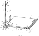
- FIGS. 1 to 4 and 8th the cabin apron is shown in its deployed position, whereas in FIG FIG. 6 the cabin apron 10 is shown in its folded position.
- the cabin apron 10 is shown in layers which are a transition from the fold-out position to the fold-in position.
- the cabin apron 10 has a skirt edge 12, which is a protruding from the apron sheet 11 profile, whereby the apron sheet 11 has a high rigidity.
- the apron sheet 11 has a Kröpflasche 14 on. With the help of Kröpflasche 14 a certain compressibility and / or foldability of the cabin apron 10 is achieved in a possible collision of the cabin apron 10 with the shaft base 4 or accidentally left on the shaft base 4 object.
- the apron proximal end 15 of the cabin apron 10 is disposed opposite the apron distal end 13 and immediately adjacent to the car door travel rail 7.
- the cabin skirt 10 has a Verschwenklager 16 as a linkage, which is formed by a bearing axis 17 and a bearing plate 18 in which a bearing hole 19 is made, through which the bearing axis 17 extends.
- the bearing axis 17 is arranged parallel to the car door travel rail 7 below the same.
- the bearing plate 18 is mounted below the car door travel rail 7, so that the cabin apron 10 is pivotally connected to the bearing plate 18 via the bearing shaft 17 on the car door travel rail 7.
- the axis line of the bearing axis 17 coincides with the horizontal axis about which the cabin skirt 10 is pivotable by means of Verschwenklagers 16.
- the car safety device 9 has a locking device 20 with which the car safety device 9 is held locked both in its folded-out position and in its folded-in position. During the transition of the car safety device 9 from the folded-out position into the folded-in position or vice versa, the car safety device 9 is unlocked so that a pivoting of the skirt sheet 11 about the bearing axis 17 is made possible. In contrast, in the locking of the locking device 20 pivoting of the skirt sheet 11 is inhibited about the bearing axis 17.
- the locking device 20 has an eccentric 21, which is attached to a longitudinal end of the bearing shaft 17 and thus eccentrically from the bearing shaft 17 is mitverformatbar.
- the eccentric 21 has a first locking surface 22 and a second locking surface 23 and a running surface 24, which is arranged in the circumferential direction of the eccentric 21 between the first locking surface 22 and the second locking surface 23.
- the first locking surface 22 and the second locking surface 23 have a radial course and limit in the circumferential direction of the tread 24 and thus the eccentric 21st
- the locking device 20 has a push rod 25 which is arranged longitudinally displaceable perpendicular to the bearing axis 17 on the cabin floor 8.
- the push rod 25 has a first push rod end 26 and a second push rod end 27, wherein the push rod ends 26, 27 facing away from each other and the first push rod end 26 is located on the eccentric 21.
- the push rod 25 has a push rod projection 28, which can be brought into engagement with the eccentric 21.
- the apron sheet 11 extends vertically from the cabin floor 8 down.
- the eccentric 21 is arranged such that its first locking surface 22 extends horizontally. In this position, the eccentric 21 and the push rod 25 are arranged relative to each other such that the push rod projection 28 above the first locking surface 22 abuts against this.
- the eccentric 21 presses with its first locking surface 22 to the push rod projection 28, whereby a pivoting of the skirt sheet 11 is prevented.
- a positive connection is formed by the push rod projection 28 and the eccentric 21, by means of which the locking of the car safety device 9 is accomplished in the folded-out position.
- the eccentric 21 is exposed and the cabin skirt 10 is pivotable about its bearing axis 17 from the folded-out position to the folded-in position.
- the cabin apron 10 is in a position between the Ausklappposition and the folding position, the eccentric 21 via the bearing shaft 17 is rotated accordingly, so that the tread 24 is arranged facing the push rod projection 28.
- a support plate 29 is provided which has a hole through which the push rod 25 extends.
- the push rod 25 is on a support stage 30, wherein between the support plate 29 and the support stage 30, a compression coil spring 31 is arranged around the push rod 25 and supported both on the support plate 29 and the support 30 such that with the compression coil spring 31, the push rod 25 is biased in the direction of the eccentric 21. Is the apron 11 in the position between the Ausklappposition and the Einklappposition the push rod projection 28 is pressed with the compression coil spring 31 on the tread 24.
- the second locking surface 23 is arranged horizontally above the push rod projection 28, wherein the push rod projection 28 is no longer in contact with the tread 24.
- the push rod 25 is longitudinally displaced by the bias of the compression coil spring 31 toward the eccentric 21, wherein the push rod projection 28 with the second locking surface 23 engages.
- the cabin apron 10 can be brought back from the folding position in the Ausklappposition, the push rod 25 is displaced away from the eccentric 21 along its longitudinal direction, so that the push rod projection 28 is no longer engaged with the eccentric 21 and thereby the eccentric for pivoting the Schürzenblatts 11 is exposed again.
- the locking device 20 has a length adjustment device 32 with which the position of the push rod projection 28 relative to the eccentric 21 is adjustable.
- the push rod 25 on a lever 33 which is pivotally mounted with a lever bearing 34 on the frame 6.
- the lever 33 is formed by two legs, between which the lever bearing 34 is arranged and which has a leg with its one longitudinal end a first Hebelanlenkung 35, on which an exposed lever roller 37 is mounted, and the other leg with a second Hebelanlenkung 36 is hinged to the second push rod end 27. If the lever roller 37 is pivoted about the lever bearing 34, the push rod 25 is brought into a longitudinal movement, wherein the circular motion of the lever roller 37 is translated by the lever 33 in a translational movement of the push rod 25.
- the locking device 20 has a donor rod 38 which is mounted vertically extending and longitudinally displaceable on the frame 6.
- the length of the donor rod 38 is dimensioned such that, when the cabin apron 10 is in its deployed position, the donor rod 38 projects beyond the crop pocket 14 of the apron sheet 11 downwardly.
- the encoder rod 38 has a top GeberstablCode 39 located at the top, which is formed chamfered and thereby has a lifting flank 40, and a lower second GeberstablFigsende 41, which is arranged facing the shaft base 4.
- the donor rod 38 is arranged on the frame 6 relative to the lever roller 37 such that when the donor rod 38 is displaced upwardly relative to the cabin floor 8, the first donor rod end 39 interacts with its lifting flank 40 with the lever roller 37, whereby the lever roller 37 of the encoder rod 38 is displaced and thereby pivoted about the lever bearing 34 so that the push rod 25 is moved away from the eccentric 21 by the lever 33. If the donor rod 38 moves downward, the lever roller 37 is held in position by the donor rod 38 until the first donor rod end 39 with its lifting flank 40 from the lift roller 37, whereby by the biasing force of the compression coil spring 31, the push rod 25 together with the Lever 33 and the lever roller 37 is returned to its original position.
- a plate 42 is mounted, with the underside of the shaft base 4 of the donor rod 38 is contacted and on its side facing away from the underside a driver stage 43 has.
- the cabin protection device 9 has a flap 44.
- the flapper 44 has a trigger bar 45, the longitudinally displaceable vertically by a bearing sleeve 6 attached to the bearing sleeve extends.
- the release rod 45 is tubular, wherein the donor rod 38 is mounted longitudinally displaceable in the trigger rod 45 and from this, wherein the trigger rod 45 is mounted longitudinally displaceable by the bearing sleeve on the frame 6.
- the trigger rod 45 and the trigger rod 45 arranged internally in the donor rod 38 are arranged telescopically to each other.
- the donor rod 38 protrudes with its second GeberstablFigsende 41 and its plate 42 from the trigger rod 45 out.
- the trigger bar 45 has an overhead first trigger bar end 46 to which an eyelet 47 is attached. Further, the trigger bar 45 has a bottom second trigger bar end 48 which forms a follower stage 49.
- the second Geberstablnature 41 is dependent on the follower stage 49, wherein the plate 42 is arranged with its driver stage 43 facing the follower stage 49. If the cabin protection device 9 with its cabin apron 10 is in the folded-out position, then the second trigger bar end 48 is arranged with its follower step 49 below the crop pocket 14 of the apron sheet 11. If the car 5 approaches the shaft bottom 4, the plate 42 comes into contact with the shaft bottom 4.
- the transmitter rod 38 is displaced upward in the trigger rod 45 and relative to the car floor 8, the transmitter rod 38 with its lifting flank 40, the lever roller 37 pushes aside and thereby the push rod 25 is moved, whereby a release of the locking device 20 is accomplished.
- the follower stage 43 of the plate 42 contacts the follower stage 49 of the second longitudinal end 48.
- the release rod 45 with the transmitter rod 38 is displaced upward relative to the cabin floor 8.
- the trigger rod 45 has a dent 50 in the region of the second trigger rod end 48.
- the dimple 50 is arranged on the trigger bar 45 such that when the Cab apron 10 is in its Einklappposition, the lever roller 37 is engaged with the dent 50, whereby the lever roller 37 is pivoted about the lever bearing 34, wherein the push rod 25 is moved back toward the eccentric 21, which of the push rod projection 28 with the second locking surface 23 a positive locking of the control device 20 is accomplished.
- the flapper 44 has a gear 51.
- the transmission 51 has as a pulling means a rope 52 and three pulleys 53 to 55, wherein the rope 52 has a first end of the rope 56 and a second end 57 of the rope.
- the rope 52 With the first end of the rope 56, the rope 52 is attached to the freestanding longitudinal end of the apron flank 12 in the region of the Kröpflasche 14 and guided to the fixed to the cabin floor 8 first guide roller 53.
- the pulleys 54 and 55 are also attached to the cabin floor 8 and guide the rope 52 with its second end of the rope 57 to the eyelet 47 of the trigger rod 45, wherein the second cable end 57 is attached to the eyelet 47.
- the eyelet 47 is moved upwards relative to the car floor 8.
- the cabin apron 10 is pulled by the cable 52 via the deflection rollers 53 to 55 from the folded-out position into the folded-in position.
- the plate 42 contacts the shaft bottom 4 in a position in which the cabin apron 10 does not yet touch the shaft bottom 4 in the folded-out position.
- the cab 5 is moved upward as the cab 5 continues moving, whereby the push rod 25 is moved away from the eccentric 21 via the lever 33 by the interaction of the lifting flank 40 and the lever roller 37, so that the latch device 20 is unlocked .
- the driver stage 43 then contacts the follower stage 49, as a result of which the trigger rod 45 is displaced upward relative to the cabin floor 8.
- the trigger rod 45 pulls the eyelet 47th attached rope 52, whereby the cabin apron 10 is pivoted from the unfolded position to the folded position.
- the dent 50 With a correspondingly small distance of the cabin floor 8 from the shaft base 4, the dent 50 is brought into the position at the height of the lever roller 37, whereby the lever roller 37 engages in the dent 50, so that the push rod 25 is displaced toward the eccentric 21, whereby the locking device 20th is locked again.
- This position of the car 8 is the lowest position in the hoistway 2.
- the donor rod 38, together with the trigger bar 45 is moved downwardly relative to the cab floor 8, causing the lever roller 37 to disengage the dent 50, thereby unlocking the latch assembly 20.
- the trigger bar 45, together with the donor rod 38 is moved downwardly relative to the cabin floor 8, thereby increasing the cable length between the first diverting pulley 53 and the skirting end 13 and thereby the cab apron 10 from the folded position to the deployed position is brought.
- the movement of the trigger bar 45 ends relative to the cabin floor 8.
- the transmitter bar 38 is moved relative to the cabin floor 8 until the lifting flank 40 is lifted off the lever roller 37, whereby the locking device 20 locks the cabin apron 10 in its Ausklappposition.
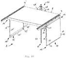
- FIGS. 10 to 14 shown second cabin aprons 10, 10 ', wherein the second cabin apron 10' a apron 11 ', a Schürzenflanke 12', a Schurzendistalende 13 ', a Kröpflasche 14' and a Schürzenproximalende 15 'analogous to the first cabin apron 10 has.
- the cabin skirts 10, 10 ' are arranged on two opposite sides of the car 5, with one of the car door travel rails 7, 7' attached to each of the sides.
- the trigger bar 45 is disposed between the cabin skirts 10, 10 'and is configured to operate both the one cabin apron 10 and the other cabin apron 10'.
- a shoulder bar 58 is fixed, which extends transversely to the release rod 45, whereby the trigger rod 45 together with the shoulder bar 58 have a T-shape.
- a shoulder joint 59 is provided, on each of which a pull rod 60, 60 'is articulated as a pulling means.
- the right pull rod 60 is coupled to the distal end 13 'of the left cabin skirt 10' by means of a skirt joint 61 ', whereas the left pull rod 60' is coupled to the distal end 13 of the right cabin skirt 10 by means of a skirt joint 61. Due to the T-shape of the trigger rod 45 and the shoulder beam 58 and the mutual assignment of the tie rods 60, 60 'to the cabin aprons 10', 10, the tie rods 60, 60 'crossed each other. As a result, the tie rods 60, 60 'arranged scissor-like.
- a guide sleeve 62 is mounted, with which the trigger rod 45 is mounted vertically displaceable.
- pins 63, 63 'for the locking device 20 are respectively attached to the left and right of the trigger rod 45.
- the locking device 20 is formed by a first shearing lever 64 and a two shear lever 65, which are fixed scissor-like via a shearing lever joint 66 together.
- the overhead longitudinal ends of the shear levers 64, 65 are coupled together with a tension coil spring 67 so that the overhead longitudinal ends of the shear arms 64, 65 are biased toward each other by a tensile force exerted by the tension coil spring 67.
- Tilting levers 68, 69 are articulated to the upper longitudinal ends of the shearing levers 64, 65, which are in turn pivotally mounted to each other at their longitudinal ends facing away from the shearing levers 64, 65 by means of a lever joint 70, wherein the lever joint 70 is attached to the first trigger rod end 46 of the trigger rod 45.
- the shear levers 64, 65 have at their longitudinal ends remote from the tension coil spring 67 each outer notches 71, 71 'which are engageable with the pins 63, 63' in engagement. At the notches 71, 71 'adjacent guide flanks 72, 72' form the lower longitudinal ends of the shear lever 64, 65th
- the first Auslöserstablteilsende 46 is arranged on the cabin floor 8 and on the guide sleeve 62, whereby the trigger rod 45 protrudes a maximum length of the cabin floor 8 down. If the car 5 is moved in the direction of the shaft bottom 4, touched in a corresponding position of the car 5 in the elevator shaft 2, the trigger rod 45 with its second Auslöserstablteilsende 48 the shaft bottom 4.
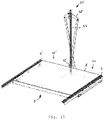
- the trigger rod 45 is moved relative to the cabin floor 8 shifted upward, whereby via the shoulder beam 58 and the tie rods 60, 60 'the cabin skirts 10, 10' inwardly below the cabin floor. 8 be folded. If the car 5 has reached its lowest point, then the cabin aprons 10, 10 'below the cabin floor 8 are folded substantially horizontally, wherein the trigger bar 45 protrudes maximum long up from the cabin floor 8. As it is in FIG. 14 is shown the cabin skirts 10, 10 'are slightly longer than half the embedding of the cabin floor 8 is formed. By a correspondingly different length of the tie rods 60, 60 ', a staggered folding of the cabin skirts 10, 10' can be accomplished, whereby a collision of the cabin skirts 10, 10 'is prevented in the folded position.
- the trigger rod 45 is displaced downwards relative to the cabin floor 8, as a result of which the cabin aprons 10, 10 'are again brought toward their deployed position.
- the shear levers 64, 65 approach the pivots 63, 63', with the guide flanks 72, 72 'touching the pivots 63, 63 from above when the cab 5 is in a corresponding position.
- the shear levers 64, 65 ' Upon further travel of the car 5 upwards, the shear levers 64, 65 'are pushed inward by the guide flanks 72, 72' at their lower longitudinal ends, overcoming the biasing force applied by the tension coil spring 67 until the notches 71, 71 'on the pins 63, 63 'engage. Then the cabin skirts 10, 10 'brought back into its Ausklappposition, wherein the locking device 20 is brought into its locked state by the engagement of the notches 71, 71' on the pin 63, 63 '. When the car 5 continues to move upwards, the cabin aprons 10, 10 'remain in their folded-out position, as a result of which the safety function of the car safety device 9 is achieved.
- the tension coil spring 67 acts as a support. Without the tension coil spring 67, the functioning of the locking device 20 is also achieved.
Landscapes
- Elevator Door Apparatuses (AREA)
- Cage And Drive Apparatuses For Elevators (AREA)
Description
Die Erfindung betrifft eine Kabinenschutzeinrichtung für eine Kabine einer Aufzuganlage.
Hält eine Kabine einer Aufzuganlage an einem Stockwerk eines Gebäudes an, so sollten der Kabinenboden und der Stockwerkboden bündig abschließen, um Kabineninsassen ein möglichst komfortables und sicheres Aussteigen aus der Kabine zu ermöglichen. Kommt die Kabine jedoch oberhalb des Stockwerkbodens zum Halten, so bildet sich eine vertikale Öffnung zwischen dem Kabinenboden und dem Stockwerkboden aus und es besteht die Gefahr, dass Personen in den Aufzugschacht stürzen. Ferner könnte beispielsweise ein in einem unteren Stockwerk ausgebrochenes Feuer durch die Öffnung zwischen dem Kabinenboden und dem Stockwerkboden auf das obere Stockwerk überschlagen.
Um dies zu verhindern ist es bekannt, unterhalb der Kabinentür eine Kabinenschürze vorzusehen, die in vertikaler Richtung nach unten, d.h. in Richtung zum Schachtgrund hin, ragt und somit die eventuelle Öffnung zwischen dem Kabinenboden und dem Stockwerkboden verschließt. Eine solche Kabinenschürze hat beispielsweise eine Dimension von 2 m2. Der Aufzugschacht bzw. die Schachtgrube müssen dabei tief genug sein, um die Kabinenschürze aufzunehmen zu können, wenn die Kabine an ihrer tiefsten Position sich befindet. Insbesondere wenn ein Aufzug nachgerüstet wird, zum Beispiel an der Außenwand eines Gebäudes, sind jedoch die Möglichkeiten zum Ausheben einer entsprechend tiefen Schachtgrube nicht gegeben oder zumindest begrenzt.
Bei niedrigen Schachtgruben ist es bekannt, eine teleskopierbare Schürze vorzusehen, die beispielsweise aus drei in vertikaler Richtung zusammenschiebbaren Paneelen besteht.The invention relates to a cabin protection device for a cabin of an elevator installation.
If a cabin of an elevator system stops at a floor of a building, the cabin floor and the floor of the floor should be flush so as to allow passengers to get out of the cabin as comfortably and safely as possible. However, if the car comes to a stop above the floor of the floor, a vertical opening is formed between the car floor and the floor of the floor and there is a risk of people falling into the elevator shaft. Further, for example, a fire that has broken out in a lower floor could roll over to the upper floor through the opening between the cabin floor and the floor of the storey.
To prevent this, it is known to provide a cabin skirt below the cabin door, which projects downwards in the vertical direction, ie in the direction of the shaft bottom, and thus closes the possible opening between the cabin floor and the floor of the storey. Such a cabin apron has for example a dimension of 2 m 2 . The elevator shaft or pit must be deep enough to accommodate the cabin apron when the cabin is at its lowest position. In particular, when an elevator is retrofitted, for example on the outer wall of a building, however, the possibilities for excavating a correspondingly deep shaft pit are not given or at least limited.
In low shaft pits, it is known to provide a telescopic apron, which consists for example of three telescoping panels in the vertical direction.
Aufgabe der Erfindung ist es, eine Kabinenschutzeinrichtung für eine Kabine einer Aufzuganlage zu schaffen, wobei die Aufzuganlage sicher betreibbar ist und dennoch die Schachtgrube lediglich flach ausgeführt zu sein braucht und die Kabinenschutzeinrichtung wartungsarm und zuverlässig ist.The object of the invention is to provide a car protection device for a cabin of an elevator installation, wherein the Elevator system is safe to operate and yet the shaft pit needs to be made only flat and the car protection device is low maintenance and reliable.
Die Aufgabe wird gelöst mit den Merkmalen des Patentanspruchs 1. Vorteilhafte Ausgestaltungen dazu sind in den weiteren Patentansprüchen angegeben.The object is solved with the features of claim 1. Advantageous embodiments thereof are given in the further claims.
Die erfindungsgemäße Kabinenschutzeinrichtung für eine Kabine einer Aufzuganlage weist mindestens eine Kabinenschürze, die an der Kabine um eine Horizontalachse verschwenkbar angelenkt ist und in ihrer Ausklappposition vertikal nach unten und in ihrer Einklappposition schräg oder horizontal jeweils unterhalb des Kabinenbodens sich erstreckt, und eine Klappeinrichtung auf, die einen Auslöserstab, der am Kabinenboden mit einem Horizontalabstand zur Horizontalachse angebracht ist und vom Kabinenboden nach unten zum Schachtgrund hin sich derart lang erstreckt, dass, wenn die Kabinenschürze in ihrer Ausklappposition ist und den Schachtgrund gerade noch nicht berührt, mit dem Auslöserstab der Schachtgrund durch Verfahren der Kabine zum Schachtgrund hin kontaktierbar ist, und mindestens ein Getriebe aufweist, das innerhalb des Horizontalabstands zwischen dem Auslöserstab und der Kabinenschürze angeordnet ist und diese miteinander koppelt, so dass, wenn beim Annähern der Kabine an den Schachtgrund der Auslöserstab diesen kontaktiert, durch die Weiterfahrt der Kabine in Richtung zum Schachtgrund hin vom Schachtgrund via den Auslöserstab und das Getriebe die Kabinenschürze von der Ausklappposition in die Einklappposition bringbar ist, wodurch eine Kollision der Kabinenschürze mit dem Schachtgrund unterbunden ist.The cabin protection device according to the invention for a cabin of an elevator installation has at least one cabin apron, which is articulated on the cabin about a horizontal axis pivotally and in its folded position vertically downwards and in its Einklappposition obliquely or horizontally extending below the cabin floor, and a flap on the, a trigger bar, which is mounted on the cabin floor with a horizontal distance to the horizontal axis and extends from the cabin floor down to the shaft base down so long that when the cabin apron is in its Ausklappposition and the shaft bottom just does not touch, with the trigger rod of the shaft bottom by method the cab is contactable to the shaft bottom, and having at least one transmission which is disposed within the horizontal distance between the trigger rod and the cabin skirt and these coupled to each other, so that when approaching the cabin the manhole base of the release rod contacted this, by the onward travel of the cabin in the direction of the shaft bottom of the shaft base via the trigger rod and the gearbox the cabin apron from the Ausklappposition can be brought into the Einklappposition, whereby a collision of the cabin apron is prevented with the shaft base.
Die Aufzuganlage ist für ein Gebäude vorgesehen, in dem ein entsprechender Aufzugschacht eingebaut ist, in dem die Aufzuganlage untergebracht ist. Beispielsweise erstreckt sich der Aufzugschacht vom Keller des Gebäudes bis zu dessen Dachgeschoss, so dass mit der Aufzuganlage jedes Stockwerk des Gebäudes erreichbar ist. Beim Betreiben der Aufzuganlage wird die Kabine in dem Aufzugschacht vertikal verfahren, wobei die Kabine in jedem Stockwerk so angehalten werden kann, dass der Kabinenboden mit dem jeweiligen Stockwerkboden bündig ist. Sollte jedoch aufgrund einer Fehlfunktion der Aufzuganlage die Kabine in einem der Stockwerke derart zum Halten kommen, dass der Kabinenboden oberhalb dieses Stockwerkbodens angeordnet ist, verbleibt zwischen dem Kabinenboden und dem Stockwerkboden eine Öffnung, durch die der Aufzugschacht vom Stockwerk her zugänglich ist. Dadurch, dass die Kabinenschürze in ihrer Ausklappposition ist, sobald der Auslöserstab den Schachtgrund nicht mehr kontaktiert, ist die Öffnung von der Kabinenschürze abgedeckt. Somit ist es unmöglich, dass beispielsweise Personen durch die Öffnung in den Aufzugschacht gelangen können.The elevator system is intended for a building in which a corresponding elevator shaft is installed, in which the elevator system is housed. For example, the elevator shaft extends from the basement of the building to its top floor, so that with the elevator system each floor of the building can be reached. When operating the elevator system is the cabin in the elevator shaft move vertically, wherein the cabin can be stopped in each floor so that the cabin floor is flush with the respective floor floor. However, if due to a malfunction of the elevator installation, the cabin in one of the floors comes to a halt such that the cabin floor is arranged above this floor, an opening remains between the cabin floor and the floor of the floor, through which the elevator shaft is accessible from the floor. The fact that the cabin apron is in its Ausklappposition as soon as the trigger rod no longer contacts the shaft base, the opening is covered by the cabin apron. Thus, it is impossible that, for example, people can get through the opening in the elevator shaft.
Fährt die Kabine im Aufzugschacht nach unten, um das Kellergeschoss anzufahren, nähert sich die Kabine dem Schachtgrund. Sobald der Auslöserstab den Schachtgrund berührt, wird beim Weiterfahren der Kabine in Richtung zum Schachtgrund hin die Kabinenschürze von ihrer Ausklappposition in ihre Einklappposition gebracht. Dadurch, dass der Auslöserstab nach unten eine längere Erstreckung als die Kabinenschürze hat, ist eine Kollision der Kabinenschürze mit dem Schachtgrund unterbunden. Sonst müsste die Schachtgrube tiefer ausgeführt sein, wodurch dann ausreichend Platz für die Kabinenschürze in der Ausklappposition bereitgestellt wäre. Durch die erfindungsgemäße Kabinenschutzeinrichtung ist es vielmehr ermöglicht, die Schachtgrube lediglich flach auszuführen, was in baulicher Hinsicht von Vorteil ist. Insbesondere bei einem Neubau braucht nur eine flache Schachtgrube vorgesehen zu werden und bei Altbauten, die mit einem Aufzug nachgerüstet werden sollen, ist häufig das Vorsehen nur einer flachen Schachtgrube möglich. Somit ist es vorteilhaft sowohl bei Neubauten als auch bei Altbauten eine Aufzuganlage mit der erfindungsgemäßen Kabinenschutzeinrichtung vorzusehen.If the cabin in the elevator shaft moves down to drive to the basement, the cabin approaches the shaft bottom. As soon as the release rod touches the shaft bottom, the cabin apron is moved from its folded-out position into its folded-in position when the cabin is moved further in the direction of the shaft bottom. Due to the fact that the release rod has a longer extension downwards than the cabin apron, a collision of the cabin apron with the shaft base is prevented. Otherwise, the pit would have to be made deeper, which would then provide sufficient space for the cabin apron in the Ausklappposition. Due to the cab protection device according to the invention, it is rather possible to perform the pit only flat, which is structurally advantageous. Especially in a new building needs only a shallow pit to be provided and in old buildings that are to be retrofitted with an elevator, the provision of only a shallow pit is often possible. Thus, it is advantageous to provide both in new buildings and in old buildings an elevator system with the cabin protection device according to the invention.
Sobald der Auslöserstab den Schachtgrund berührt und die Kabine weiter nach unten zum Schachtgrund hin verfahren wird, findet eine Kraftübertragung vom Schachtgrund auf den Auslöserstab durch das Eigengewicht der Kabine statt. Mit dem Getriebe, das zwischen dem Auslöserstab und der Kabinenschürze in ihrer Ausklappposition angeordnet ist, wird die Kraft vom Auslöserstab auf die Kabinenschürze derart übertragen, dass die Kabinenschürze von ihrer Ausklappposition in ihre Einklappposition gebracht wird. Somit wird der Antrieb der Kabinenschürze beim Einklappen durch das Eigengewicht der Kabine und ihrer Bewegung nach unten bewerkstelligt, so dass etwa ein zusätzlicher Antrieb zum Bewegen der Kabinenschürze nicht vorgesehen zu werden braucht. Außerdem braucht etwa eine Stromzufuhr zu dem Antrieb ebenfalls vorteilhaft nicht vorgesehen zu werden. Somit ist die Kabinenschutzeinrichtung unabhängig von jeder Energiezufuhr von außen autark betreibbar, wodurch die Kabinenschutzeinrichtung einfach und zuverlässig ist und lediglich einen geringen Wartungsaufwand erforderlich macht.As soon as the trigger rod touches the shaft bottom and the cabin is moved further down to the shaft bottom, there is a force transmission from the shaft bottom to the trigger rod held by the dead weight of the cabin. With the transmission disposed between the trigger bar and the cab apron in its deployed position, the force from the trigger bar is transferred to the cab apron such that the cab apron is brought from its deployed position to its fold-in position. Thus, the drive of the cabin apron when folding by the weight of the cabin and its movement is accomplished downwards, so that about an additional drive for moving the cabin apron need not be provided. In addition, about a power supply to the drive also advantageously not to be provided. Thus, the car protection device is independently operable independently of any external power supply, whereby the car protection device is simple and reliable and only requires a low maintenance required.
Sobald sich die Kabine im Keller befindet, ist die Kabinenschürze in der Einklappposition. Dadurch wäre eine etwaige Öffnung zwischen dem Kabinenboden und dem Kellerboden von der Kabinenschürze nicht abgedeckt. Dies ist jedoch unkritisch, da die Schachtgrube des Aufzugsschachts ohnehin nur flach ausgebildet zu sein braucht.Once the cabin is in the basement, the cabin apron is in the folded position. This would not cover any opening between the cabin floor and the basement floor of the cabin apron. However, this is not critical, since the pit of the elevator shaft needs to be formed only flat anyway.
Dadurch, dass der Auslöserstab durch das Verfahren der Kabine angetrieben wird, ist es ausreichend, wenn der Verfahrweg der Kabine via das Getriebe bei einer Übersetzung von Eins auf die Kabinenschürze übertragen wird. Somit ist erreicht, dass die Kabinenschürze nicht zu langsam von der Ausklappposition in die Einklappposition überführt wird und eine Kollision der Kabinenschürze mit dem Schachtgrund ist unterbunden. Das Getriebe mit der Übersetzung Eins ist vorteilhaft sehr einfach ausgeführt.By driving the trigger bar through the cab process, it is sufficient if the travel of the cab is transmitted via the transmission at a ratio of one to the cab apron. Thus, it is achieved that the cabin apron is not transferred too slowly from the unfolded position to the folded-in position and a collision of the cabin apron with the shaft base is prevented. The transmission with the ratio one is advantageous very simple.
Das Getriebe weist bevorzugt ein Zugmittel auf, das sowohl an dem Auslöserstab als auch an der Kabinenschürze festgelegt ist, wodurch via das Zugmittel die Kabinenschürze von dem Auslöserstab zum Bringen von der Ausklappposition in die Einklappposition antreibbar ist. Bevorzugtermaßen ist das Zugmittel ein Seil oder eine Zugstange. Das Zugseil ist bevorzugtermaßen um Umlenkrollen geführt.The transmission preferably has a traction means which is fixed both to the trigger rod and to the cabin apron, whereby via the traction means the cabin apron of the trigger rod for bringing from the Ausklappposition in the Einklappposition is drivable. Preferred dimensions of the traction means is a rope or a tie rod. The traction cable is preferably guided around deflection rollers.
Ferner ist es bevorzugt, dass das Getriebe ein Zahnrad aufweist, das an der Kabinenschürze derart befestigt ist, dass die Horizontalachse, um die die Kabinenschürze verschwenkbar ist, mit der Drehachse des Zahnrads zusammenfällt, wobei der Auslöserstab eine Längsverzahnung aufweist, die mit dem Zahnrad in Eingriff steht, wodurch bei einer Längsbewegung des Auslöserstabs via das Zahnrad die Kabinenschürze von ihrer Einklappposition in ihre Ausklappposition bringbar ist. Das Getriebe weist vorteilhaft wenige und in ihrer Funktion zuverlässige Bauteile auf, wodurch der Wartungsaufwand für die Kabinenschutzeinrichtung gering ist.Further, it is preferred that the transmission comprises a gear fixed to the cab apron such that the horizontal axis about which the cab apron is pivotal coincides with the axis of rotation of the gear, the trigger bar having a serration integral with the gear Intervention is, whereby during a longitudinal movement of the trigger rod via the gear, the cabin apron can be brought from its folded position into its Ausklappposition. The transmission advantageously has few and functionally reliable components, whereby the maintenance of the car protection device is low.
Die Klappschutzeinrichtung weist bevorzugtermaßen zwei einander gegenüberliegende Kabinenschürzen und für jede der Kabinenschürzen jeweils eines der Zugmittel auf, wobei der Auslöserstab zwischen den Kabinenschürzen angeordnet ist. Soll die Kabine von zwei einander gegenüberliegenden Seiten von einem Stockwerk aus zugänglich sein, ermöglichen die beiden einander gegenüberliegenden Kabinenschürzen einen sicheren Betrieb der Aufzuganlage. Dadurch, dass für die beiden Kabinenschürzen nur ein einziger Auslöserstab vorgesehen ist, ist der Aufbau der Kabinenschutzeinrichtung einfach und sicher im Betrieb.The folding protection device preferably has two cabin skirts facing one another and one of the traction means for each of the cabin aprons, wherein the trigger bar is arranged between the cabin skirts. If the cabin is to be accessible from two opposite sides from one floor, the two cabin skirts located opposite one another enable safe operation of the elevator installation. The fact that only a single release rod is provided for the two cabin aprons, the structure of the cabin protection device is simple and safe in operation.
Alternativ ist es bevorzugt, dass die Klappschutzeinrichtung eine einzige Kabinenschürze aufweist, die an einer Seite der Kabine angelenkt ist, und der Auslöserstab an einer der einen Seite gegenüberliegenden anderen Seite angeordnet ist, wobei das Zugmittel den Abstand zwischen der einen Seite und der anderen Seite überbrückt.Alternatively, it is preferred that the folding protection device comprises a single cabin apron which is hinged to one side of the cabin, and the trigger bar is arranged on one side opposite the other side, wherein the traction means bridges the distance between the one side and the other side ,
Der Auslöserstab ist bevorzugt an der Kabine entlang seiner Längrichtung verschiebbar gelagert. Ferner ist es bevorzugt, dass die Kabinenschürze zwischen ihrer Anlenkung an der Kabine und der Festlegung des Zugmittels starr ausgebildet ist. Dadurch weist die erfindungsgemäße Kabinenschutzeinrichtung wenige bewegliche Teile auf, die lediglich zumindest einen geringen Verschleiß haben.The trigger bar is preferably mounted displaceably on the cabin along its longitudinal direction. Furthermore, it is preferred that the cabin apron between its articulation on the cabin and the determination of the traction means is rigid. As a result, the cabin protection device according to the invention has a few moving parts, which merely have at least a slight wear.
Die Kabinenschutzeinrichtung weist bevorzugtermaßen eine Riegeleinrichtung auf, mit der die Kabinenschürze in ihrer Einklappposition und/oder in ihrer Ausklappposition verriegelbar ist. Dadurch ist es unterbunden, dass, wenn mit der Kabinenschürze eine Öffnung zwischen dem Kabinenboden und einem Stockwerkboden abgedeckt ist, die Kabinenschürze etwa in den Aufzugschacht hineingedrückt werden kann.The cabin protection device preferably has a locking device with which the cabin apron can be locked in its folded-in position and / or in its folded-out position. This prevents that when the cabin apron covers an opening between the cabin floor and a storey floor, the cabin apron can be pressed into the elevator shaft approximately.
Die Riegeleinrichtung weist bevorzugt einen Geberstab auf, der derart angeordnet ist, dass beim Annähern der Kabine an den Schachtgrund der Geberstab vor dem Auslöserstab den Schachtgrund kontaktiert, wodurch eine Entriegelung der Riegeleinrichtung durchführbar ist. Die Funktionsweise des Geberstabs ist analog zu der des Auslöserstabs, wobei via den Geberstab durch das Eigengewicht der Kabine beim nach unten Fahren eine Kraft vom Schachtgrund auf die Riegeleinrichtung zum Verriegeln und/oder zum Entriegeln der Riegeleinrichtung übertragbar ist. Dadurch braucht etwa für die erfindungsgemäße Kabinenschutzeinrichtung kein separater Antrieb mit entsprechender Energiezuführung für die Riegeleinrichtung vorgesehen zu werden.The locking device preferably has a donor rod, which is arranged such that when approaching the car to the shaft bottom of the donor rod in front of the trigger rod contacted the manhole base, thereby unlocking the locking device is feasible. The operation of the donor rod is analogous to that of the trigger rod, wherein via the donor rod by the weight of the cab when driving down a force from the shaft base on the locking device for locking and / or unlocking the locking device is transferable. As a result, it is not necessary to provide a separate drive with a corresponding energy supply for the locking device for the cabin protection device according to the invention.
Alternativ weist die Riegeleinrichtung ein Vorspannmittel auf, das mit dem Auslöserstab gekoppelt ist, wobei der Auslöserstab mit dem Vorspannmittel derart zusammenwirkt, dass, sobald der Auslöserstab beim Annähern der Kabine an den Schachtgrund diesen kontaktiert und eine Vorspannkraft des Vorspannmittels durch den Auslöserstab überwunden ist, eine Entriegelung der Riegeleinrichtung durchführbar ist. Dadurch braucht etwa ein Geberstab zur Handhabung der Riegeleinrichtung nicht vorgesehen zu werden und mit dem Auslöserstab sind sowohl das Verschwenken der Kabinenschürze als auch die Betätigung der Riegeleinrichtung bewerkstelligt.Alternatively, the latch means comprises biasing means coupled to the trigger bar, the trigger bar cooperating with the biasing means such that once the trigger bar contacts the shaft base as the car approaches the shaft base and a biasing force of the biasing means is overcome by the trigger bar Unlocking the locking device is feasible. As a result, about a donor rod for handling the locking device does not need to be provided and with the trigger rod both the pivoting of the cabin apron and the operation of the locking device are accomplished.
Im Folgenden wird die Erfindung anhand bevorzugter Ausführungsformen mit Bezugnahme auf die Zeichnungen erläutert. Es zeigen:
-
Figuren 1 bis 9 schematische Darstellungen einer Aufzuganlage mit einer ersten bevorzugten Ausführungsform der erfindungsgemäßen Kabinenschutzeinrichtung und -
Figuren 10 bis 14
-
FIGS. 1 to 9 schematic representations of an elevator system with a first preferred embodiment of the cabin protection device according to the invention and -
FIGS. 10 to 14 schematic representations of an elevator system with a second preferred embodiment of the cabin protection device according to the invention.
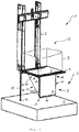
Wie es aus den Figuren ersichtlich ist, weist eine Aufzuganlage 1 einen Aufzugschacht 2 auf, dessen unteres Ende von einer Schachtgrube 3 gebildet ist. Der Boden der Schachtgrube 3 ist der Schachtgrund 4. Eine Kabine 5 der Aufzuganlage 1 ist im Aufzugschacht 2 zum Vertikalverfahren angeordnet. Hierzu weist die Aufzuganlage 1 im Aufzugschacht 2 Verfahrschienen (nicht gezeigt) auf, an denen entlang die Kabine 5 mit ihrem Rahmen 6 vertikal verfahrbar gelagert ist. Die Kabine 5 weist ferner eine Kabinentür (nicht gezeigt) auf, durch die die Kabine 5 von außerhalb etwa einem Stockwerk, in das die Kabine 5 gefahren ist, zugänglich ist. Die Kabinentür ist teleskopierend ausgebildet, so dass am Kabinenboden 8 der Kabine 5 für die Kabinentür eine Kabinentürverfahrschiene 7 vorgesehen ist. Die Aufzuganlage 1 gemäß den
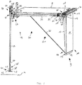
Im Folgenden wird eine erste Ausführungsform einer Kabinenschutzeinrichtung 9 gemäß den
Für die seitliche Berandung der Kabinenschürze 11 weist die Kabinenschürze 10 eine Schürzenflanke 12 auf, die ein vom Schürzenblatt 11 vorstehendes Profil ist, wodurch das Schürzenblatt 11 eine hohe Steifigkeit hat. Am Schürzendistalende 13 der Kabinenschürze 10, das der Kabinenverfahrtürschiene 7 angewandt angeordnet ist, weist das Schürzenblatt 11 eine Kröpflasche 14 auf. Mit Hilfe der Kröpflasche 14 ist bei einer eventuellen Kollision der Kabinenschürze 10 mit dem Schachtgrund 4 oder einem versehentlich am Schachtgrund 4 liegen gelassenen Gegenstand eine gewisse Stauchbarkeit und/oder Faltbarkeit der Kabinenschürze 10 erreicht.For the lateral boundary of the
Das Schürzenproximalende 15 der Kabinenschürze 10 ist dem Schürzendistalende 13 gegenüberliegend und unmittelbar benachbart zur Kabinentürverfahrschiene 7 angeordnet. Am Schürzenproximalende 15 weist die Kabinenschürze 10 ein Verschwenklager 16 als eine Anlenkung auf, das von einer Lagerachse 17 und einer Lagerplatte 18 gebildet ist, in der ein Lagerloch 19 gefertigt ist, durch das die Lagerachse 17 sich erstreckt. Die Lagerachse 17 ist parallel zur Kabinentürverfahrschiene 7 unterhalb derselben angeordnet. Die Lagerplatte 18 ist unterhalb an der Kabinentürverfahrschiene 7 befestigt, so dass die Kabinenschürze 10 an der Lagerplatte 18 via die Lagerachse 17 an der Kabinentürverfahrschiene 7 verschwenkbar angelenkt ist. Die Achslinie der Lagerachse 17 fällt mit der Horizontalachse zusammen, um die die Kabinenschürze 10 mittels des Verschwenklagers 16 verschwenkbar ist.The apron
Die Kabinenschutzeinrichtung 9 weist eine Riegeleinrichtung 20 auf, mit der die Kabinenschutzeinrichtung 9 sowohl in ihrer Ausklappposition als auch in ihrer Einklappposition verriegelt gehalten ist. Beim Übergang der Kabinenschutzeinrichtung 9 von der Ausklappposition in die Einklappposition oder umgekehrt ist die Kabinenschutzeinrichtung 9 entriegelt, so dass ein Verschwenken des Schürzenblatts 11 um die Lagerachse 17 ermöglicht ist. In Gegensatz dazu ist bei der Verriegelung der Riegeleinrichtung 20 ein Verschwenken des Schürzenblatts 11 um die Lagerachse 17 gehemmt.The
Die Riegeleinrichtung 20 weist einen Exzenter 21 auf, der an einem Längsende der Lagerachse 17 befestigt ist und somit exzentrisch von der Lagerachse 17 mitverdrehbar ist. Der Exzenter 21 weist eine erste Verriegelungsfläche 22 und eine zweite Verriegelungsfläche 23 sowie eine Lauffläche 24 auf, die in Umfangsrichtung des Exzenters 21 gesehen zwischen der ersten Verriegelungsfläche 22 und der zweiten Verriegelungsfläche 23 angeordnet ist. Die erste Verriegelungsfläche 22 und die zweite Verriegelungsfläche 23 haben einen radialen Verlauf und begrenzen in Umfangsrichtung die Lauffläche 24 und somit den Exzenter 21.The locking
Die Riegeleinrichtung 20 weist einen Schubstab 25 auf, der senkrecht zur Lagerachse 17 am Kabinenboden 8 längsverschiebbar angeordnet ist. Der Schubstab 25 hat ein erstes Schubstablängsende 26 und ein zweites Schubstablängsende 27, wobei die Schubstablängsenden 26, 27 einander abgewandt sind und das erste Schubstablängsende 26 am Exzenter 21 angesiedelt ist. Am ersten Schubstablängsende 26 weist der Schubstab 25 einen Schubstabvorsprung 28 auf, der mit dem Exzenter 21 in Eingriff bringbar ist.The locking
Ist die Kabinenschutzeinrichtung 9 in ihrer Ausklappposition, erstreckt sich das Schürzenblatt 11 senkrecht vom Kabinenboden 8 nach unten. Der Exzenter 21 ist derart angeordnet, dass seine erste Verriegelungsfläche 22 horizontal sich erstreckt. In dieser Position sind der Exzenter 21 und der Schubstab 25 relativ zueinander derart angeordnet, dass der Schubstabvorsprung 28 oberhalb der ersten Verriegelungsfläche 22 an dieser anliegt. Würde das Schürzenblatt 11 von der Ausklappposition in die Einklappposition gedrückt werden, drückt der Exzenter 21 mit seiner ersten Verriegelungsfläche 22 an den Schubstabvorsprung 28, wodurch ein Verschwenken des Schürzenblatts 11 unterbunden ist. Dadurch ist von dem Schubstabvorsprung 28 und dem Exzenter 21 eine formschlüssige Verbindung ausgebildet, durch die das Verriegeln der Kabinenschutzeinrichtung 9 in der Ausklappposition bewerkstelligt ist.Is the
Ist der Schubstab 25 von der Lagerachse 17 weg versetzt verschoben angeordnet, so dass der Schubstabvorsprung 28 mit dem Exzenter 21 nicht mehr in Eingriff steht, ist der Exzenter 21 freigelegt und die Kabinenschürze 10 ist um ihre Lagerachse 17 von der Ausklappposition in die Einklappposition verschwenkbar. Befindet sich die Kabinenschürze 10 in einer Lage zwischen der Ausklappposition und der Einklappposition, ist der Exzenter 21 via die Lagerachse 17 entsprechend mit verdreht, so dass die Lauffläche 24 dem Schubstabvorsprung 28 zugewandt angeordnet ist.If the
Am Kabinenboden 8 festgelegt ist eine Abstützplatte 29 vorgesehen, die ein Loch aufweist, durch die der Schubstab 25 sich erstreckt. Zwischen der Abstützplatte 29 und dem Schubstabvorsprung 28 weist der Schubstab 25 eine Abstützstufe 30 auf, wobei zwischen der Abstützplatte 29 und der Abstützstufe 30 eine Druckschraubenfeder 31 um den Schubstab 25 und sowohl an der Abstützplatte 29 als auch an der Abstützstufe 30 abgestützt derart angeordnet ist, dass mit der Druckschraubenfeder 31 der Schubstab 25 in Richtung zum Exzenter 21 vorgespannt ist. Befindet sich das Schürzenblatt 11 in der Lage zwischen der Ausklappposition und der Einklappposition wird der Schubstabvorsprung 28 mit der Druckschraubenfeder 31 auf die Lauffläche 24 gedrückt. Erreicht beim Verschwenken des Schürzenblatts 11 aus der Ausklappposition in die Einklappposition die Kabinenschürze 10 die Einklappposition, so ist die zweite Verriegelungsfläche 23 horizontal verlaufend oberhalb des Schubstabvorsprungs 28 angeordnet, wobei der Schubstabvorsprung 28 nicht mehr mit der Lauffläche 24 in Kontakt steht. Nun wird der Schubstab 25 durch die Vorspannung der Druckschraubenfeder 31 in Richtung zum Exzenter 21 hin längsverschoben, wobei der Schubstabvorsprung 28 mit der zweiten Verriegelungsfläche 23 in Eingriff gerät. Dadurch ist ein Verschwenken des Schürzenblatts 11 aus der Einklappposition heraus unterbunden, da die Kabinenschürze 10 durch die formschlüssige Verbindung des Schubstabvorsprungs 28 mit der zweiten Verriegelungsfläche 23 verriegelt ist. Damit die Kabinenschürze 10 von der Einklappposition wieder in die Ausklappposition gebracht werden kann, ist der Schubstab 25 weg vom Exzenter 21 entlang seiner Längsrichtung zu verschieben, so dass der Schubstabvorsprung 28 mit dem Exzenter 21 nicht mehr in Eingriff steht und dadurch der Exzenter zum Verschwenken des Schürzenblatts 11 wieder freigelegt ist.Fixed to the
Das Zusammenwirken zwischen Schubstab 25 und Exzenter 21 ist nur möglich, wenn eine entsprechende Positionierung des Schubstabs 25 relativ zum Exzenter 21 ermöglicht ist. Um die entsprechende Positionierung in der Aufzuganlage 1 vor Ort vornehmen zu können, weist die Riegeleinrichtung 20 eine Längenjustiereinrichtung 32 auf, mit der die Position des Schubstabvorsprungs 28 relativ zum Exzenter 21 justierbar ist.The interaction between the
Am zweiten Schubstablängsende 27 weist der Schubstab 25 einen Hebel 33 auf, der mit einem Hebellager 34 am Rahmen 6 verschwenkbar gelagert ist. Der Hebel 33 ist von zwei Schenkeln gebildet, zwischen denen das Hebellager 34 angeordnet ist und der eine Schenkel mit seinem einen Längsende eine erste Hebelanlenkung 35 aufweist, an der eine freigelegte Hebelrolle 37 abgebracht ist, und der andere Schenkel mit einer zweiten Hebelanlenkung 36 am zweiten Schubstablängsende 27 angelenkt ist. Wird die Hebelrolle 37 um das Hebellager 34 verschwenkt, wird der Schubstab 25 in eine Längsbewegung gebracht, wobei die Kreisbewegung der Hebelrolle 37 vom Hebel 33 in eine Translationsbewegung des Schubstabs 25 übersetzt wird.At the second
Die Riegeleinrichtung 20 weist einen Geberstab 38 auf, der vertikal verlaufend und längsverschiebbar am Rahmen 6 gelagert ist. Die Länge des Geberstabs 38 ist derart bemessen, dass, wenn die Kabinenschürze 10 in ihrer Ausklappposition ist, der Geberstab 38 über die Kröpflasche 14 des Schürzenblatts 11 nach unten hinausragt. Der Geberstab 38 weist ein oben gelegenes erstes Geberstablängsende 39, das angefast ausgebildet ist und dadurch eine Anhebeflanke 40 aufweist, und ein untenliegendes zweites Geberstablängsende 41 auf, das dem Schachtgrund 4 zugewandt angeordnet ist. Der Geberstab 38 ist am Rahmen 6 relativ zur Hebelrolle 37 derart angeordnet, dass, wenn der Geberstab 38 nach oben relativ zum Kabinenboden 8 verschoben wird, das erste Geberstablängsende 39 mit ihrer Anhebeflanke 40 mit der Hebelrolle 37 in Wechselwirkung tritt, wodurch die Hebelrolle 37 von dem Geberstab 38 verdrängt wird und dadurch um das Hebellager 34 so verschwenkt wird, dass der Schubstab 25 weg vom Exzenter 21 durch den Hebel 33 bewegt wird. Wird der Geberstab 38 nach unten bewegt, wird die Hebelrolle 37 vom Geberstab 38 so lange in Position gehalten, bis das erste Geberstablängsende 39 mit ihrer Anhebeflanke 40 sich von der Heberrolle 37 entfernt, wodurch durch die Vorspannkraft der Druckschraubenfeder 31 der Schubstab 25 zusammen mit dem Hebel 33 und der Hebelrolle 37 wieder in die ursprüngliche Position gebracht wird.The locking
Am zweiten Geberstablängsende 41 ist ein Teller 42 angebracht, wobei mit dessen Unterseite der Schachtgrund 4 von dem Geberstab 38 kontaktierbar ist und der an seiner der Unterseite abgewandten Seite eine Mitnehmerstufe 43 aufweist.At the
Die Kabinenschutzeinrichtung 9 weist eine Klappeinrichtung 44 auf. Die Klappeinrichtung 44 weist einen Auslöserstab 45 auf, der längsverschiebbar vertikal durch eine am Rahmen 6 befestigte Lagerhülse sich erstreckt. Der Auslöserstab 45 ist rohrförmig ausgebildet, wobei der Geberstab 38 im Auslöserstab 45 und von diesem längsverschiebbar gelagert ist, wobei der Auslöserstab 45 von der Lagerhülse am Rahmen 6 längsverschiebbar gelagert ist. Der Auslöserstab 45 und der im Auslöserstab 45 innenliegend angeordnete Geberstab 38 sind zueinander teleskopierend eingerichtet. Der Geberstab 38 ragt mit seinem zweiten Geberstablängsende 41 und seinem Teller 42 aus dem Auslöserstab 45 heraus.The
Der Auslöserstab 45 hat ein obenliegendes erstes Auslöserstablängsende 46, an dem eine Öse 47 angebracht ist. Ferner hat der Auslöserstab 45 ein untenliegendes zweites Auslöserstablängsende 48, das eine Folgerstufe 49 ausbildet. Das zweite Geberstablängsende 41 steht von der Folgerstufe 49 ab, wobei der Teller 42 mit seiner Mitnehmerstufe 43 der Folgerstufe 49 zugewandt angeordnet ist. Befindet sich die Kabinenschutzeinrichtung 9 mit ihrer Kabinenschürze 10 in der Ausklappposition, dann ist das zweite Auslöserstablängsende 48 mit seiner Folgerstufe 49 unterhalb der Kröpflasche 14 des Schürzenblatts 11 angeordnet. Nähert sich die Kabine 5 dem Schachtgrund 4, kommt es zum Kontakt des Tellers 42 mit dem Schachtgrund 4. Bewegt sich die Kabine 5 weiter nach unten, wird der Geberstab 38 im Auslöserstab 45 und relativ zum Kabinenboden 8 nach oben verschoben, wobei der Geberstab 38 mit seiner Anhebeflanke 40 die Hebelrolle 37 zur Seite schiebt und dadurch der Schubstab 25 verschoben wird, wodurch eine Entriegelung der Riegeleinrichtung 20 bewerkstelligt wird. Sobald die Entriegelung der Riegeleinrichtung 20 eingetreten ist, kontaktiert die Mitnehmerstufe 43 des Tellers 42 die Folgerstufe 49 des zweiten Aulöserstablängsendes 48. Dadurch wird der Auslöserstab 45 mit dem Geberstab 38 relativ zum Kabinenboden 8 nach oben verschoben.The
Der Auslöserstab 45 weist im Bereich des zweiten Auslöserstablängsendes 48 eine Delle 50 auf. Die Delle 50 ist derart am Auslöserstab 45 angeordnet, dass, wenn die Kabinenschürze 10 in ihrer Einklappposition ist, die Hebelrolle 37 mit der Delle 50 in Eingriff steht, wodurch die Hebelrolle 37 um das Hebellager 34 verschwenkt ist, wobei der Schubstab 25 wieder in Richtung zum Exzenter 21 hin verschoben ist, womit von dem Schubstabvorsprung 28 mit der zweiten Verriegelungsfläche 23 eine formschlüssige Verriegelung der Regeleinrichtung 20 bewerkstelligt ist.The
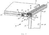
Die Klappeinrichtung 44 weist ein Getriebe 51 auf. Das Getriebe 51 weist als ein Zugmittel ein Seil 52 und drei Umlenkrollen 53 bis 55 auf, wobei das Seil 52 ein erstes Seilende 56 und ein zweites Seilende 57 hat. Mit dem ersten Seilende 56 ist das Seil 52 am freistehenden Längsende der Schürzenflanke 12 im Bereich der Kröpflasche 14 befestigt und zur am Kabinenboden 8 befestigten ersten Umlenkrolle 53 geführt. Die Umlenkrollen 54 und 55 sind ebenfalls am Kabinenboden 8 befestigt und führen das Seil 52 mit seinem zweiten Seilende 57 zur Öse 47 des Auslöserstabs 45, wobei an der Öse 47 das zweite Seilende 57 befestigt ist. Fährt die Kabine 6 nach unten und wird vom Schachtgrund 4 relativ zur Kabine 5 gesehen der Geberstab 38 nach oben bewegt, wobei der Geberstab 38 den Auslöserstab 45 mitnimmt, wird die Öse 47 relativ zum Kabinenboden 8 nach oben bewegt. Dadurch wird mit dem Seil 52 über die Umlenkrollen 53 bis 55 die Kabinenschürze 10 von der Ausklappposition in die Einklappposition gezogen.The
Fährt die Kabine 5 nach unten dem Schachtgrund 4 entgegen, berührt der Teller 42 den Schachtgrund 4 in einer Position, in der die Kabinenschürze 10 in der Ausklappposition gerade den Schachtgrund 4 noch nicht berührt. Relativ zum Kabinenboden 8 gesehen wird bei Weiterfahrt der Kabine 5 der Geberstab 38 nach oben verschoben, wodurch durch das Zusammenwirken der Anhebeflanke 40 und der Hebelrolle 37 der Schubstab 25 via den Hebel 33 vom Exzenter 21 weg bewegt wird, so dass die Riegeleinrichtung 20 entriegelt wird. Daraufhin berührt die Mitnehmerstufe 43 die Folgerstufe 49, wodurch der Auslöserstab 45 relativ zum Kabinenboden 8 gesehen nach oben verschoben wird. Dadurch zieht der Auslöserstab 45 das an der Öse 47 befestigte Seil 52, wodurch die Kabinenschürze 10 von der Ausklappposition in die Einklappposition verschwenkt wird. Bei entsprechend geringem Abstand des Kabinenbodens 8 vom Schachtgrund 4 ist die Delle 50 in die Position auf Höhe der Hebelrolle 37 gebracht, wodurch die Hebelrolle 37 in die Delle 50 eingreift, so dass der Schubstab 25 zum Exzenter 21 hin verschoben wird, wodurch die Riegeleinrichtung 20 wieder verriegelt ist. Diese Position der Kabine 8 ist die im Aufzugschacht 2 am tiefsten gelegene Position.If the
Fährt die Kabine 5 hoch, wird der Geberstab 38 zusammen mit dem Auslöserstab 45 relativ zum Kabinenboden 8 gesehen nach unten bewegt, wodurch die Hebelrolle 37 mit der Delle 50 außer Eingriff gerät und dadurch die Riegeleinrichtung 20 wieder entriegelt wird. Bei Weiterfahrt der Kabine 5 nach oben wird relativ zum Kabinenboden 8 gesehen der Auslöserstab 45 zusammen mit dem Geberstab 38 nach unten bewegt, wodurch die Seillänge zwischen der ersten Umlenkrolle 53 und dem Schürzendistalende 13 länger wird und dadurch die Kabinenschürze 10 von der Einklappposition in die Ausklappposition gebracht wird. Sobald die Kabinenschürze 10 in der Ausklappposition ist, endet die Bewegung des Auslöserstabs 45 relativ zum Kabinenboden 8. Bei Weiterfahrt der Kabine 5 nach oben wird der Geberstab 38 relativ zum Kabinenboden 8 so weit bewegt, bis die Anhebeflanke 40 von der Hebelrolle 37 abgehoben ist, wodurch die Riegeleinrichtung 20 die Kabinenschürze 10 in ihrer Ausklappposition verriegelt.When the
Die in den
Der Auslöserstab 45 ist zwischen den Kabinenschürzen 10, 10' angeordnet und ist zum Betätigen sowohl der einen Kabinenschürze 10 als auch der anderen Kabinenschürze 10' eingerichtet. Am ersten Auslöserstablängsende 46 ist statt der Öse 47 gemäß der ersten Ausführungsform ein Schulterbalken 58 befestigt, der sich quer zum Auslöserstab 45 erstreckt, wodurch der Auslöserstab 45 zusammen mit dem Schulterbalken 58 eine T-Form haben. An den Längsenden des Schulterbalkens 58 ist jeweils ein Schultergelenk 59 vorgesehen, an dem jeweils eine Zugstange 60, 60' als ein Zugmittel angelenkt ist. In den
Am Kabinenboden 8 ist eine Führungshülse 62 angebracht, mit der der Auslöserstab 45 vertikal verschiebbar gelagert ist. An der Führungshülse 62 sind jeweils links und rechts vom Auslöserstab 45 Zapfen 63, 63' für die Riegeleinrichtung 20 angebracht. Bei der zweiten Ausführungsform ist die Riegeleinrichtung 20 von einem ersten Scherhebel 64 und einem zweien Scherhebel 65 gebildet, die via ein Scherhebelgelenk 66 scherenartig aneinander festgelegt sind. Die obenliegenden Längsenden der Scherhebel 64, 65 sind mit einer Zugschraubenfeder 67 miteinander gekoppelt, so dass die obenliegenden Längsenden der Scherhebel 64, 65 durch eine von der Zugschraubenfeder 67 ausgeübten Zugkraft zueinander vorgespannt sind. An den obenliegenden Längsenden der Scherhebel 64, 65 sind jeweils Kipphebel 68, 69 angelenkt, die ihrerseits an ihren den Scherhebeln 64, 65 abgewandten Längsenden mittels eines Hebelgelenks 70 miteinander verschwenkbar gelagert sind, wobei das Hebelgelenk 70 am ersten Auslöserstablängsende 46 des Auslöserstabs 45 befestigt ist.At the
Die Scherhebel 64, 65 weisen an ihren der Zugschraubenfeder 67 abgewandten Längsenden jeweils außenliegende Kerben 71, 71' auf, die mit den Zapfen 63, 63' in Eingriff bringbar sind. An den Kerben 71, 71' angrenzenden Führungsflanken 72, 72' formen die untenliegenden Längsenden der Scherhebel 64, 65.The shear levers 64, 65 have at their longitudinal ends remote from the
In der Ausklappposition der Kabinenschutzeinrichtung 9 sind die Kerben 71, 71' mit den Zapfen 63, 63' in Eingriff gebracht. Dadurch ist das erste Auslöserstablängsende 46 am Kabinenboden 8 bzw. an der Führungshülse 62 angeordnet, wodurch der Auslöserstab 45 maximal lang vom Kabinenboden 8 nach unten vorsteht. Wird die Kabine 5 in Richtung zum Schachtgrund 4 hin verfahren, berührt in entsprechender Position der Kabine 5 im Aufzugschacht 2 der Auslöserstab 45 mit seinem zweiten Auslöserstablängsende 48 den Schachtgrund 4. Bei einer entsprechenden Weiterfahrt der Kabine 5 nach unten wird von dem Schachtgrund 4 auf den Auslöserstab 45 eine Kraft ausgeübt, die dazu führt, dass via das Hebelgelenk 70 und den Kipphebeln 68, 69 die obenliegenden Längsenden der Scherhebel 64, 65 zueinander bewegt werden, wobei die Vorspannkraft der Zugschraubenfeder 47 überwunden wird. Dabei bewegen sich die untenliegenden Längsenden der Scherhebel 64, 65 nach innen, wobei die Kerben 71, 71' von den Zapfen 63, 63' außer Eingriff geraten. Dadurch ist der Auslöserstab 45 an der Führungshülse 62 in Vertikalrichtung verschiebbar freigelegt. Bei entsprechendem Weiterfahren der Kabine 5 nach unten zum Schachtgrund 4 hin wird nun der Auslöserstab 45 relativ zum Kabinenboden 8 gesehen nach oben verschoben, wodurch via den Schulterbalken 58 und den Zugstangen 60, 60' die Kabinenschürzen 10, 10' nach innen unterhalb des Kabinenbodens 8 eingeklappt werden. Ist die Kabine 5 an ihrem tiefsten Punkt angelangt, so sind die Kabinenschürzen 10, 10' unterhalb des Kabinenbodens 8 im Wesentlichen horizontal verlaufend eingeklappt, wobei der Auslöserstab 45 maximal lang nach oben vom Kabinenboden 8 vorsteht. Wie es in
Wird die Kabine 5 im Aufzugschacht 2 wieder nach oben verfahren, wird der Auslöserstab 45 relativ zum Kabinenboden 8 nach unten verschoben, wodurch die Kabinenschürzen 10, 10' wieder in Richtung zu ihrer Ausklappposition gebracht werden. Nähern sich die Kabinenschürzen 10, 10' ihrer Ausklappposition, so nähern sich die Scherhebel 64, 65 den Zapfen 63, 63', wobei bei entsprechender Position der Kabine 5 die Führungsflanken 72, 72' von oben her die Zapfen 63, 63 berühren. Bei entsprechender Weiterfahrt der Kabine 5 nach oben werden die Scherhebel 64, 65 von den Führungsflanken 72, 72' an ihren untenliegenden Längsenden nach innen unter Überwindung der von der Zugschraubenfeder 67 aufgebrachten Vorspannkraft nach innen gedrückt, bis die Kerben 71, 71' an den Zapfen 63, 63' einrasten. Dann sind die Kabinenschürzen 10, 10' wieder in ihre Ausklappposition gebracht, wobei durch das Einrasten der Kerben 71, 71' an den Zapfen 63, 63' die Riegeleinrichtung 20 in ihren Verriegelungszustand gebracht ist. Bei entsprechender Weiterfahrt der Kabine 5 nach oben verharren die Kabinenschürzen 10, 10' in ihrer Ausklappposition, wodurch die Sicherungsfunktion der Kabinenschutzeinrichtung 9 erzielt ist. Für das Funktionieren der Riegeleinrichtung 20 wirkt die Zugschraubenfeder 67 unterstützend. Ohne der Zugschraubenfeder 67 ist die Funktionieren der Riegeleinrichtung 20 ebenfalls erzielt.If the
- 11
- Aufzuganlageelevator system
- 22
- Aufzugschachtelevator shaft
- 33
- Schachtgrubepit
- 44
- SchachtgrundSchacht reason
- 55
- Kabinecabin
- 66
- Rahmenframe
- 7, 7'7, 7 '
- KabinentürverfahrschieneKabinentürverfahrschiene
- 88th
- Kabinenbodencabin floor
- 99
- KabinenschutzeinrichtungCab guard
- 10, 10'10, 10 '
- Kabinenschürzecar apron
- 11, 11'11, 11 '
- Schürzenblattapron sheet
- 12, 12'12, 12 '
- Schürzenflankeapron edge
- 13, 13'13, 13 '
- SchürzendistalendeSchürzendistalende
- 14, 14'14, 14 '
- KröpflascheKröpflasche
- 15, 15'15, 15 '
- SchürzenproximalendeSchürzenproximalende
- 1616
- VerschwenklagerVerschwenklager
- 1717
- Lagerachsebearing axle
- 1818
- Lagerplattebearing plate
- 1919
- Lagerlochbearing hole
- 2020
- Riegeleinrichtunglocking device
- 2121
- Excentereccentric
- 2222
- erste Verriegelungsflächefirst locking surface
- 2323
- zweite Verriegelungsflächesecond locking surface
- 2424
- Laufflächetread
- 2525
- Schubstabpush rod
- 2626
- erstes Schubstablängsendefirst push rod end
- 2727
- zweites Schubstablängsendesecond push rod end
- 2828
- SchubstabvorsprungThrust bar tab
- 2929
- Abstützplattesupport plate
- 3030
- AbstützstufeAbstützstufe
- 3131
- DruckschraubenfederCompression coil spring
- 3232
- LängenjustiereinrichtungLängenjustiereinrichtung
- 3333
- Hebellever
- 3434
- Hebellagerlever bearing
- 3535
- erste Hebelanlenkungfirst lever linkage
- 3636
- zweite Hebelanlenkungsecond lever linkage
- 3737
- Hebelrollelever
- 3838
- Geberstabdonors staff
- 3939
- erstes Geberstablängsendefirst encoder rod end
- 4040
- Anhebeflankelifting edge
- 4141
- zweites Geberstablängsendesecond encoder rod end
- 4242
- TellerPlate
- 4343
- MitnehmerstufeMitnehmerstufe
- 4444
- Klappeinrichtungfolding device
- 4545
- Auslöserstabtrigger bar
- 4646
- erstes Auslöserstablängsendefirst trigger rod end
- 4747
- Öseeyelet
- 4848
- zweites Auslöserstablängsendesecond trigger rod end
- 4949
- Folgerstufefollower stage
- 5050
- Delledent
- 5151
- Getriebetransmission
- 5252
- Seilrope
- 5353
- erste Umlenkrollefirst pulley
- 5454
- zweite Umlenkrollesecond deflection roller
- 5555
- dritte Umlenkrollethird pulley
- 5656
- erstes Seilendefirst rope end
- 5757
- zweites Seilendesecond rope end
- 5858
- Schulterbalkenshoulder bar
- 5959
- Schultergelenkshoulder joint
- 60, 60'60, 60 '
- Zugstangepull bar
- 61, 61'61, 61 '
- Schürzengelenkapron joint
- 6262
- Führungshülseguide sleeve
- 63, 63'63, 63 '
- Zapfenspigot
- 6464
- erster Scherhebelfirst shearing lever
- 6565
- zweiter Scherhebelsecond shearing lever
- 6666
- ScherhebelgelenkShear lever joint
- 6767
- Zugschraubenfedertension coil spring
- 6868
- erster Kipphebelfirst rocker arm
- 6969
- zweiter Kipphebelsecond rocker arm
- 7070
- Hebelgelenklever joint
- 71, 71'71, 71 '
- Kerbescore
- 72, 72'72, 72 '
- FührungsfankeFührungsfanke
Claims (10)
- Cabin protection device (9) for a cabin (5) of an elevator system (1), wherein the cabin protection device (9) comprises a cabin apron (10; 10, 10') that is pivotally linked to the cabin (5) around a horizontal axis and wherein the cabin apron (10; 10, 10') extends in its fold-out position vertically downwards and in its fold-in position transversely or horizontally respectively below the cabin bottom (8), wherein the cabin protection device (9) comprises a folding device (44) that comprises a trigger stick (45) that is arranged with a horizontal distance to the horizontal axis, and wherein the trigger stick (45) extends such long downwards towards the shaft bottom (4) that, if the cabin apron (10; 10, 10') is in its fold-out position and contacts the shaft bottom (4) not just yet, the shaft bottom (4) is contactable with the trigger stick (45) by moving the cabin (5) towards the shaft bottom (4), wherein the folding device (44) comprises at least one gear (51) that is arranged within the horizontal distance between the trigger stick (45) and the cabin apron (10; 10, 10'), and wherein the gear (51) couples the trigger stick (45) with the cabin apron (10; 10, 10') so that, if the trigger stick (45) contacts the shaft bottom (4) while approaching the cabin (5) to the shaft bottom (4), the cabin apron (10; 10, 10') can be brought from the fold-out position to the fold-in position via the trigger stick (45) and the gear (51) by further driving of the cabin (5) towards the shaft bottom (4), whereby a collision of the cabin apron (10; 10, 10') with the shaft bottom (4) is prevented, characterized in that the trigger stick (45) is arranged at the cabin bottom (8) and extends from the cabin bottom (8) downwards towards the shaft bottom (4).
- Cabin protection device (9) according to claim 1, wherein the gear (51) comprises tensile means (52; 60, 60') that are fixed to the trigger stick (45) as well as to the cabin apron (10), whereby the cabin apron (10; 10, 10') is driveable via the tensile means (52; 60, 60') by the trigger sick (45) for bringing the cabin apron (10; 10, 10') from the fold-out position to the fold-in position.
- Cabin protection device (9) according to claim 2, wherein the cabin protection device (9) comprises two opposing cabin aprons (10; 10') and for each of the cabin aprons (10; 10') respectively one of the tensile means (60, 60'), and wherein the trigger stick (45) is arranged between the cabin aprons (10; 10').
- Cabin protection device (9) according to claim 2, wherein the cabin protection device (9) comprises a single cabin apron (10) that is linked to one side of the cabin (5), and wherein the trigger stick (45) is arranged at another side that is opposite to the one side, wherein the tensile means (52) bridges the distance between the one side and the other side.
- Cabin protection device (9) according to any one of the claims 2 to 4, wherein the tensile means (52; 60, 60') is a rope (52) or a tensile rod (60, 60').
- Cabin protection device (9) according to any one of the claims 1 to 5, wherein the trigger stick (45) is slideably supported at the cabin (5) along its longitudinal direction.
- Cabin protection device (9) according to any one of the claims 1 to 6, wherein the cabin apron (10; 10, 10') is formed rigidly between its linkage (16) to the cabin (5) and the fixing of the tensile means (52; 60, 60').
- Cabin protection device (9) according to any one of the claims 1 to 7, wherein the cabin protection device (9) comprises a locking device (20) with which the cabin apron (10; 10, 10') is lockable in its fold-in position and/or in its fold-out position.
- Cabin protection device (9) according to claim 8, wherein the locking device (20) comprises a sensor stick (38) that is arranged such that the sensor stick (38) contacts the shaft bottom (4) before the trigger stick (45) while the cabin (5) is approaching the shaft bottom (4), whereby an unlocking of the locking device (20) is performable.
- Cabin protection device (9) according to claim 8, wherein the locking device (20) comprises biasing means (67) that are coupled with the trigger stick (45), wherein the trigger stick (45) interacts with the bias means (67) such that an unlocking of the locking device (20) is performable as soon as the trigger stick (45) contacts the shaft bottom (4) while approaching the cabin (5) to the shaft bottom (4) and a biasing force of the biasing means (67) is overcome by the trigger stick (45).
Priority Applications (1)
| Application Number | Priority Date | Filing Date | Title |
|---|---|---|---|
| PL17174090T PL3251995T3 (en) | 2016-06-02 | 2017-06-01 | Cab protection device for a cab of a lift system |
Applications Claiming Priority (1)
| Application Number | Priority Date | Filing Date | Title |
|---|---|---|---|
| DE102016110249.0A DE102016110249A1 (en) | 2016-06-02 | 2016-06-02 | Cabin protection device for a cabin of an elevator installation |
Publications (2)
| Publication Number | Publication Date |
|---|---|
| EP3251995A1 EP3251995A1 (en) | 2017-12-06 |
| EP3251995B1 true EP3251995B1 (en) | 2018-12-26 |
Family
ID=59009543
Family Applications (1)
| Application Number | Title | Priority Date | Filing Date |
|---|---|---|---|
| EP17174090.5A Not-in-force EP3251995B1 (en) | 2016-06-02 | 2017-06-01 | Cab protection device for a cab of a lift system |
Country Status (4)
| Country | Link |
|---|---|
| EP (1) | EP3251995B1 (en) |
| DE (1) | DE102016110249A1 (en) |
| ES (1) | ES2715970T3 (en) |
| PL (1) | PL3251995T3 (en) |
Families Citing this family (3)
| Publication number | Priority date | Publication date | Assignee | Title |
|---|---|---|---|---|
| ES2912314T3 (en) | 2018-08-10 | 2022-05-25 | Otis Elevator Co | elevator car apron |
| WO2021063962A1 (en) * | 2019-09-30 | 2021-04-08 | Inventio Ag | Elevator system |
| CN114516575B (en) * | 2022-02-11 | 2023-11-07 | 内蒙古大唐国际托克托发电有限责任公司 | Unpowered safe self-locking system |
Family Cites Families (4)
| Publication number | Priority date | Publication date | Assignee | Title |
|---|---|---|---|---|
| IT251255Y1 (en) * | 2000-07-28 | 2003-11-19 | Selcom Spa | MOBILE PARAMENT IN LIFT OR ELEVATOR CABIN |
| DE102008038409B4 (en) * | 2007-08-28 | 2016-12-22 | Thoma Aufzüge Gmbh | Device for securing manhole access of elevator installations |
| ES2597969T3 (en) * | 2011-04-05 | 2017-01-24 | Otis Elevator Company | Toe protection set for a lifting system |
| IL215654A (en) * | 2011-10-10 | 2015-01-29 | Yoram Madar | Foldable apron in elevator with moveable floor in reduced pit |
-
2016
- 2016-06-02 DE DE102016110249.0A patent/DE102016110249A1/en not_active Withdrawn
-
2017
- 2017-06-01 PL PL17174090T patent/PL3251995T3/en unknown
- 2017-06-01 EP EP17174090.5A patent/EP3251995B1/en not_active Not-in-force
- 2017-06-01 ES ES17174090T patent/ES2715970T3/en active Active
Non-Patent Citations (1)
| Title |
|---|
| None * |
Also Published As
| Publication number | Publication date |
|---|---|
| PL3251995T3 (en) | 2019-07-31 |
| DE102016110249A1 (en) | 2017-12-07 |
| ES2715970T3 (en) | 2019-06-07 |
| EP3251995A1 (en) | 2017-12-06 |
Similar Documents
| Publication | Publication Date | Title |
|---|---|---|
| EP1772414B1 (en) | Foldable self-locking toe guard for elevator car | |
| EP2243742B1 (en) | Scissor lifting platform | |
| EP1497217B1 (en) | Device for actuating and locking elevator doors comprising driving runners | |
| DE69926244T2 (en) | Shaft safety system for lift | |
| EP2287104B1 (en) | Door coupler and locking mechanism | |
| EP3251995B1 (en) | Cab protection device for a cab of a lift system | |
| AT413529B (en) | DEVICE FOR ACTUATING AND LOCKING OF LIFTING DOORS | |
| EP1541518B1 (en) | Door drive device for an elevator | |
| EP2185457B1 (en) | Lift-car door which, in order to open the car, can be moved optionally upwards or downwards over its entire vertical length | |
| EP1760026B1 (en) | Method for carrying out maintenance and inspection work in an elevator system | |
| EP1826342B1 (en) | Sectional gate with escape door | |
| DE10065101A1 (en) | Elevator has movable protective device beneath elevator cabin with at least one rotation axis or shaft for pivoting the device and locking arrangement for fixing deployed protective device | |
| DE102006002184B4 (en) | Method for motor-driven lifting of a scissors pedestal and scissors pedestal | |
| EP2836454B1 (en) | Method for positioning anti-transport element of a shaft door of a lift assembly | |
| EP3538410B1 (en) | Rail vehicle having interior portions at different floor levels | |
| EP1726560B1 (en) | Scissor type lifting table | |
| DE3543214C2 (en) | ||
| EP3666719A1 (en) | Wheel chock automatic device | |
| EP2050703B1 (en) | Lift assembly for people and/or loads with at least one lift cabin | |
| EP3152378B1 (en) | Sliding door | |
| DE102012104987A1 (en) | Exit step for flight compartment of rail vehicles, has projecting handles arranged in guide groove, and guide tube axially and slidably guided in cab next to opening of cab door, where groove is rotatably connected with upper draw bar | |
| EP4267815B1 (en) | A rail-guided climbing system | |
| DE20202775U1 (en) | Elevator with a temporary shelter | |
| EP2072449B1 (en) | Door operation device for lift systems | |
| DE2106983A1 (en) | Telescopic crane boom |
Legal Events
| Date | Code | Title | Description |
|---|---|---|---|
| PUAI | Public reference made under article 153(3) epc to a published international application that has entered the european phase |
Free format text: ORIGINAL CODE: 0009012 |
|
| STAA | Information on the status of an ep patent application or granted ep patent |
Free format text: STATUS: THE APPLICATION HAS BEEN PUBLISHED |
|
| STAA | Information on the status of an ep patent application or granted ep patent |
Free format text: STATUS: REQUEST FOR EXAMINATION WAS MADE |
|
| AK | Designated contracting states |
Kind code of ref document: A1 Designated state(s): AL AT BE BG CH CY CZ DE DK EE ES FI FR GB GR HR HU IE IS IT LI LT LU LV MC MK MT NL NO PL PT RO RS SE SI SK SM TR |
|
| AX | Request for extension of the european patent |
Extension state: BA ME |
|
| 17P | Request for examination filed |
Effective date: 20171116 |
|
| RBV | Designated contracting states (corrected) |
Designated state(s): AL AT BE BG CH CY CZ DE DK EE ES FI FR GB GR HR HU IE IS IT LI LT LU LV MC MK MT NL NO PL PT RO RS SE SI SK SM TR |
|
| GRAP | Despatch of communication of intention to grant a patent |
Free format text: ORIGINAL CODE: EPIDOSNIGR1 |
|
| STAA | Information on the status of an ep patent application or granted ep patent |
Free format text: STATUS: GRANT OF PATENT IS INTENDED |
|
| INTG | Intention to grant announced |
Effective date: 20180618 |
|
| GRAS | Grant fee paid |
Free format text: ORIGINAL CODE: EPIDOSNIGR3 |
|
| GRAJ | Information related to disapproval of communication of intention to grant by the applicant or resumption of examination proceedings by the epo deleted |
Free format text: ORIGINAL CODE: EPIDOSDIGR1 |
|
| GRAL | Information related to payment of fee for publishing/printing deleted |
Free format text: ORIGINAL CODE: EPIDOSDIGR3 |
|
| STAA | Information on the status of an ep patent application or granted ep patent |
Free format text: STATUS: REQUEST FOR EXAMINATION WAS MADE |
|
| GRAP | Despatch of communication of intention to grant a patent |
Free format text: ORIGINAL CODE: EPIDOSNIGR1 |
|
| STAA | Information on the status of an ep patent application or granted ep patent |
Free format text: STATUS: GRANT OF PATENT IS INTENDED |
|
| INTC | Intention to grant announced (deleted) | ||
| GRAA | (expected) grant |
Free format text: ORIGINAL CODE: 0009210 |
|
| STAA | Information on the status of an ep patent application or granted ep patent |
Free format text: STATUS: THE PATENT HAS BEEN GRANTED |
|
| INTG | Intention to grant announced |
Effective date: 20181029 |
|
| AK | Designated contracting states |
Kind code of ref document: B1 Designated state(s): AL AT BE BG CH CY CZ DE DK EE ES FI FR GB GR HR HU IE IS IT LI LT LU LV MC MK MT NL NO PL PT RO RS SE SI SK SM TR |
|
| REG | Reference to a national code |
Ref country code: GB Ref legal event code: FG4D Free format text: NOT ENGLISH |
|
| REG | Reference to a national code |
Ref country code: CH Ref legal event code: EP |
|
| REG | Reference to a national code |
Ref country code: AT Ref legal event code: REF Ref document number: 1081126 Country of ref document: AT Kind code of ref document: T Effective date: 20190115 |
|
| REG | Reference to a national code |
Ref country code: DE Ref legal event code: R096 Ref document number: 502017000562 Country of ref document: DE |
|
| REG | Reference to a national code |
Ref country code: IE Ref legal event code: FG4D Free format text: LANGUAGE OF EP DOCUMENT: GERMAN |
|
| REG | Reference to a national code |
Ref country code: CH Ref legal event code: NV Representative=s name: BRAUNPAT BRAUN EDER AG, CH |
|
| REG | Reference to a national code |
Ref country code: SE Ref legal event code: TRGR |
|
| REG | Reference to a national code |
Ref country code: NL Ref legal event code: FP |
|
| PG25 | Lapsed in a contracting state [announced via postgrant information from national office to epo] |
Ref country code: LT Free format text: LAPSE BECAUSE OF FAILURE TO SUBMIT A TRANSLATION OF THE DESCRIPTION OR TO PAY THE FEE WITHIN THE PRESCRIBED TIME-LIMIT Effective date: 20181226 Ref country code: HR Free format text: LAPSE BECAUSE OF FAILURE TO SUBMIT A TRANSLATION OF THE DESCRIPTION OR TO PAY THE FEE WITHIN THE PRESCRIBED TIME-LIMIT Effective date: 20181226 Ref country code: BG Free format text: LAPSE BECAUSE OF FAILURE TO SUBMIT A TRANSLATION OF THE DESCRIPTION OR TO PAY THE FEE WITHIN THE PRESCRIBED TIME-LIMIT Effective date: 20190326 Ref country code: LV Free format text: LAPSE BECAUSE OF FAILURE TO SUBMIT A TRANSLATION OF THE DESCRIPTION OR TO PAY THE FEE WITHIN THE PRESCRIBED TIME-LIMIT Effective date: 20181226 |
|
| REG | Reference to a national code |
Ref country code: LT Ref legal event code: MG4D |
|
| PG25 | Lapsed in a contracting state [announced via postgrant information from national office to epo] |
Ref country code: RS Free format text: LAPSE BECAUSE OF FAILURE TO SUBMIT A TRANSLATION OF THE DESCRIPTION OR TO PAY THE FEE WITHIN THE PRESCRIBED TIME-LIMIT Effective date: 20181226 Ref country code: AL Free format text: LAPSE BECAUSE OF FAILURE TO SUBMIT A TRANSLATION OF THE DESCRIPTION OR TO PAY THE FEE WITHIN THE PRESCRIBED TIME-LIMIT Effective date: 20181226 |
|
| REG | Reference to a national code |
Ref country code: GR Ref legal event code: EP Ref document number: 20190400878 Country of ref document: GR Effective date: 20190524 Ref country code: ES Ref legal event code: FG2A Ref document number: 2715970 Country of ref document: ES Kind code of ref document: T3 Effective date: 20190607 |
|
| REG | Reference to a national code |
Ref country code: NO Ref legal event code: T2 Effective date: 20181226 |
|
| PG25 | Lapsed in a contracting state [announced via postgrant information from national office to epo] |
Ref country code: PT Free format text: LAPSE BECAUSE OF FAILURE TO SUBMIT A TRANSLATION OF THE DESCRIPTION OR TO PAY THE FEE WITHIN THE PRESCRIBED TIME-LIMIT Effective date: 20190426 Ref country code: CZ Free format text: LAPSE BECAUSE OF FAILURE TO SUBMIT A TRANSLATION OF THE DESCRIPTION OR TO PAY THE FEE WITHIN THE PRESCRIBED TIME-LIMIT Effective date: 20181226 |
|
| PGFP | Annual fee paid to national office [announced via postgrant information from national office to epo] |
Ref country code: PT Payment date: 20190327 Year of fee payment: 3 Ref country code: PL Payment date: 20190530 Year of fee payment: 3 Ref country code: FI Payment date: 20190618 Year of fee payment: 3 |
|
| PG25 | Lapsed in a contracting state [announced via postgrant information from national office to epo] |
Ref country code: EE Free format text: LAPSE BECAUSE OF FAILURE TO SUBMIT A TRANSLATION OF THE DESCRIPTION OR TO PAY THE FEE WITHIN THE PRESCRIBED TIME-LIMIT Effective date: 20181226 Ref country code: SM Free format text: LAPSE BECAUSE OF FAILURE TO SUBMIT A TRANSLATION OF THE DESCRIPTION OR TO PAY THE FEE WITHIN THE PRESCRIBED TIME-LIMIT Effective date: 20181226 Ref country code: RO Free format text: LAPSE BECAUSE OF FAILURE TO SUBMIT A TRANSLATION OF THE DESCRIPTION OR TO PAY THE FEE WITHIN THE PRESCRIBED TIME-LIMIT Effective date: 20181226 Ref country code: IS Free format text: LAPSE BECAUSE OF FAILURE TO SUBMIT A TRANSLATION OF THE DESCRIPTION OR TO PAY THE FEE WITHIN THE PRESCRIBED TIME-LIMIT Effective date: 20190426 Ref country code: SK Free format text: LAPSE BECAUSE OF FAILURE TO SUBMIT A TRANSLATION OF THE DESCRIPTION OR TO PAY THE FEE WITHIN THE PRESCRIBED TIME-LIMIT Effective date: 20181226 |
|
| PGFP | Annual fee paid to national office [announced via postgrant information from national office to epo] |
Ref country code: FR Payment date: 20190626 Year of fee payment: 3 Ref country code: GR Payment date: 20190619 Year of fee payment: 3 Ref country code: SE Payment date: 20190624 Year of fee payment: 3 |
|
| REG | Reference to a national code |
Ref country code: DE Ref legal event code: R097 Ref document number: 502017000562 Country of ref document: DE |
|
| PG25 | Lapsed in a contracting state [announced via postgrant information from national office to epo] |
Ref country code: DK Free format text: LAPSE BECAUSE OF FAILURE TO SUBMIT A TRANSLATION OF THE DESCRIPTION OR TO PAY THE FEE WITHIN THE PRESCRIBED TIME-LIMIT Effective date: 20181226 |
|
| PGFP | Annual fee paid to national office [announced via postgrant information from national office to epo] |
Ref country code: ES Payment date: 20190723 Year of fee payment: 3 |
|
| PLBE | No opposition filed within time limit |
Free format text: ORIGINAL CODE: 0009261 |
|
| STAA | Information on the status of an ep patent application or granted ep patent |
Free format text: STATUS: NO OPPOSITION FILED WITHIN TIME LIMIT |
|
| 26N | No opposition filed |
Effective date: 20190927 |
|
| PG25 | Lapsed in a contracting state [announced via postgrant information from national office to epo] |
Ref country code: MC Free format text: LAPSE BECAUSE OF FAILURE TO SUBMIT A TRANSLATION OF THE DESCRIPTION OR TO PAY THE FEE WITHIN THE PRESCRIBED TIME-LIMIT Effective date: 20181226 |
|
| PG25 | Lapsed in a contracting state [announced via postgrant information from national office to epo] |
Ref country code: SI Free format text: LAPSE BECAUSE OF FAILURE TO SUBMIT A TRANSLATION OF THE DESCRIPTION OR TO PAY THE FEE WITHIN THE PRESCRIBED TIME-LIMIT Effective date: 20181226 |
|
| REG | Reference to a national code |
Ref country code: BE Ref legal event code: MM Effective date: 20190630 |
|
| PG25 | Lapsed in a contracting state [announced via postgrant information from national office to epo] |
Ref country code: TR Free format text: LAPSE BECAUSE OF FAILURE TO SUBMIT A TRANSLATION OF THE DESCRIPTION OR TO PAY THE FEE WITHIN THE PRESCRIBED TIME-LIMIT Effective date: 20181226 |
|
| PG25 | Lapsed in a contracting state [announced via postgrant information from national office to epo] |
Ref country code: IE Free format text: LAPSE BECAUSE OF NON-PAYMENT OF DUE FEES Effective date: 20190601 |
|
| REG | Reference to a national code |
Ref country code: DE Ref legal event code: R082 Ref document number: 502017000562 Country of ref document: DE Representative=s name: PATERIS THEOBALD ELBEL & PARTNER, PATENTANWAEL, DE Ref country code: DE Ref legal event code: R082 Ref document number: 502017000562 Country of ref document: DE Representative=s name: PATERIS THEOBALD ELBEL FISCHER, PATENTANWAELTE, DE Ref country code: DE Ref legal event code: R082 Ref document number: 502017000562 Country of ref document: DE Representative=s name: PATERIS PATENTANWAELTE, PARTMBB, DE |
|
| PG25 | Lapsed in a contracting state [announced via postgrant information from national office to epo] |
Ref country code: BE Free format text: LAPSE BECAUSE OF NON-PAYMENT OF DUE FEES Effective date: 20190630 Ref country code: LU Free format text: LAPSE BECAUSE OF NON-PAYMENT OF DUE FEES Effective date: 20190601 |
|
| PGFP | Annual fee paid to national office [announced via postgrant information from national office to epo] |
Ref country code: IT Payment date: 20200630 Year of fee payment: 4 |
|
| REG | Reference to a national code |
Ref country code: FI Ref legal event code: MAE |
|
| REG | Reference to a national code |
Ref country code: NO Ref legal event code: MMEP |
|
| PG25 | Lapsed in a contracting state [announced via postgrant information from national office to epo] |
Ref country code: FI Free format text: LAPSE BECAUSE OF NON-PAYMENT OF DUE FEES Effective date: 20200601 |
|
| REG | Reference to a national code |
Ref country code: CH Ref legal event code: PL |
|
| REG | Reference to a national code |
Ref country code: NL Ref legal event code: MM Effective date: 20200701 |
|
| PG25 | Lapsed in a contracting state [announced via postgrant information from national office to epo] |
Ref country code: FR Free format text: LAPSE BECAUSE OF NON-PAYMENT OF DUE FEES Effective date: 20200630 Ref country code: GR Free format text: LAPSE BECAUSE OF NON-PAYMENT OF DUE FEES Effective date: 20210111 Ref country code: CH Free format text: LAPSE BECAUSE OF NON-PAYMENT OF DUE FEES Effective date: 20200630 Ref country code: LI Free format text: LAPSE BECAUSE OF NON-PAYMENT OF DUE FEES Effective date: 20200630 Ref country code: NO Free format text: LAPSE BECAUSE OF NON-PAYMENT OF DUE FEES Effective date: 20200630 |
|
| PG25 | Lapsed in a contracting state [announced via postgrant information from national office to epo] |
Ref country code: CY Free format text: LAPSE BECAUSE OF FAILURE TO SUBMIT A TRANSLATION OF THE DESCRIPTION OR TO PAY THE FEE WITHIN THE PRESCRIBED TIME-LIMIT Effective date: 20181226 Ref country code: SE Free format text: LAPSE BECAUSE OF NON-PAYMENT OF DUE FEES Effective date: 20200602 |
|
| PG25 | Lapsed in a contracting state [announced via postgrant information from national office to epo] |
Ref country code: HU Free format text: LAPSE BECAUSE OF FAILURE TO SUBMIT A TRANSLATION OF THE DESCRIPTION OR TO PAY THE FEE WITHIN THE PRESCRIBED TIME-LIMIT; INVALID AB INITIO Effective date: 20170601 Ref country code: MT Free format text: LAPSE BECAUSE OF FAILURE TO SUBMIT A TRANSLATION OF THE DESCRIPTION OR TO PAY THE FEE WITHIN THE PRESCRIBED TIME-LIMIT Effective date: 20181226 |
|
| REG | Reference to a national code |
Ref country code: SE Ref legal event code: EUG |
|
| REG | Reference to a national code |
Ref country code: ES Ref legal event code: FD2A Effective date: 20211026 |
|
| PG25 | Lapsed in a contracting state [announced via postgrant information from national office to epo] |
Ref country code: ES Free format text: LAPSE BECAUSE OF NON-PAYMENT OF DUE FEES Effective date: 20200602 |
|
| GBPC | Gb: european patent ceased through non-payment of renewal fee |
Effective date: 20210601 |
|
| PG25 | Lapsed in a contracting state [announced via postgrant information from national office to epo] |
Ref country code: GB Free format text: LAPSE BECAUSE OF NON-PAYMENT OF DUE FEES Effective date: 20210601 |
|
| PG25 | Lapsed in a contracting state [announced via postgrant information from national office to epo] |
Ref country code: MK Free format text: LAPSE BECAUSE OF FAILURE TO SUBMIT A TRANSLATION OF THE DESCRIPTION OR TO PAY THE FEE WITHIN THE PRESCRIBED TIME-LIMIT Effective date: 20181226 |
|
| PG25 | Lapsed in a contracting state [announced via postgrant information from national office to epo] |
Ref country code: IT Free format text: LAPSE BECAUSE OF NON-PAYMENT OF DUE FEES Effective date: 20210601 |
|
| PGFP | Annual fee paid to national office [announced via postgrant information from national office to epo] |
Ref country code: DE Payment date: 20220602 Year of fee payment: 6 |
|
| PG25 | Lapsed in a contracting state [announced via postgrant information from national office to epo] |
Ref country code: PL Free format text: LAPSE BECAUSE OF NON-PAYMENT OF DUE FEES Effective date: 20200601 |
|
| PG25 | Lapsed in a contracting state [announced via postgrant information from national office to epo] |
Ref country code: NL Free format text: LAPSE BECAUSE OF NON-PAYMENT OF DUE FEES Effective date: 20200701 |
|
| REG | Reference to a national code |
Ref country code: AT Ref legal event code: MM01 Ref document number: 1081126 Country of ref document: AT Kind code of ref document: T Effective date: 20220601 |
|
| PG25 | Lapsed in a contracting state [announced via postgrant information from national office to epo] |
Ref country code: AT Free format text: LAPSE BECAUSE OF NON-PAYMENT OF DUE FEES Effective date: 20220601 |
|
| REG | Reference to a national code |
Ref country code: DE Ref legal event code: R119 Ref document number: 502017000562 Country of ref document: DE |
|
| PG25 | Lapsed in a contracting state [announced via postgrant information from national office to epo] |
Ref country code: DE Free format text: LAPSE BECAUSE OF NON-PAYMENT OF DUE FEES Effective date: 20240103 |