EP3251895B1 - Vorrichtung zur beleuchtung und/oder signalisierung für kraftfahrzeug - Google Patents
Vorrichtung zur beleuchtung und/oder signalisierung für kraftfahrzeug Download PDFInfo
- Publication number
- EP3251895B1 EP3251895B1 EP17170689.8A EP17170689A EP3251895B1 EP 3251895 B1 EP3251895 B1 EP 3251895B1 EP 17170689 A EP17170689 A EP 17170689A EP 3251895 B1 EP3251895 B1 EP 3251895B1
- Authority
- EP
- European Patent Office
- Prior art keywords
- signalling device
- fan
- base
- directional lighting
- support piece
- Prior art date
- Legal status (The legal status is an assumption and is not a legal conclusion. Google has not performed a legal analysis and makes no representation as to the accuracy of the status listed.)
- Active
Links
Images
Classifications
-
- F—MECHANICAL ENGINEERING; LIGHTING; HEATING; WEAPONS; BLASTING
- F21—LIGHTING
- F21V—FUNCTIONAL FEATURES OR DETAILS OF LIGHTING DEVICES OR SYSTEMS THEREOF; STRUCTURAL COMBINATIONS OF LIGHTING DEVICES WITH OTHER ARTICLES, NOT OTHERWISE PROVIDED FOR
- F21V17/00—Fastening of component parts of lighting devices, e.g. shades, globes, refractors, reflectors, filters, screens, grids or protective cages
- F21V17/10—Fastening of component parts of lighting devices, e.g. shades, globes, refractors, reflectors, filters, screens, grids or protective cages characterised by specific fastening means or way of fastening
- F21V17/104—Fastening of component parts of lighting devices, e.g. shades, globes, refractors, reflectors, filters, screens, grids or protective cages characterised by specific fastening means or way of fastening using feather joints, e.g. tongues and grooves, with or without friction
-
- F—MECHANICAL ENGINEERING; LIGHTING; HEATING; WEAPONS; BLASTING
- F21—LIGHTING
- F21S—NON-PORTABLE LIGHTING DEVICES; SYSTEMS THEREOF; VEHICLE LIGHTING DEVICES SPECIALLY ADAPTED FOR VEHICLE EXTERIORS
- F21S45/00—Arrangements within vehicle lighting devices specially adapted for vehicle exteriors, for purposes other than emission or distribution of light
- F21S45/40—Cooling of lighting devices
- F21S45/42—Forced cooling
- F21S45/43—Forced cooling using gas
-
- B—PERFORMING OPERATIONS; TRANSPORTING
- B60—VEHICLES IN GENERAL
- B60Q—ARRANGEMENT OF SIGNALLING OR LIGHTING DEVICES, THE MOUNTING OR SUPPORTING THEREOF OR CIRCUITS THEREFOR, FOR VEHICLES IN GENERAL
- B60Q1/00—Arrangement of optical signalling or lighting devices, the mounting or supporting thereof or circuits therefor
- B60Q1/02—Arrangement of optical signalling or lighting devices, the mounting or supporting thereof or circuits therefor the devices being primarily intended to illuminate the way ahead or to illuminate other areas of way or environments
- B60Q1/04—Arrangement of optical signalling or lighting devices, the mounting or supporting thereof or circuits therefor the devices being primarily intended to illuminate the way ahead or to illuminate other areas of way or environments the devices being headlights
- B60Q1/0408—Arrangement of optical signalling or lighting devices, the mounting or supporting thereof or circuits therefor the devices being primarily intended to illuminate the way ahead or to illuminate other areas of way or environments the devices being headlights built into the vehicle body, e.g. details concerning the mounting of the headlamps on the vehicle body
- B60Q1/0425—Arrangement of optical signalling or lighting devices, the mounting or supporting thereof or circuits therefor the devices being primarily intended to illuminate the way ahead or to illuminate other areas of way or environments the devices being headlights built into the vehicle body, e.g. details concerning the mounting of the headlamps on the vehicle body the housing being swivel mounted on the vehicle body
-
- B—PERFORMING OPERATIONS; TRANSPORTING
- B60—VEHICLES IN GENERAL
- B60Q—ARRANGEMENT OF SIGNALLING OR LIGHTING DEVICES, THE MOUNTING OR SUPPORTING THEREOF OR CIRCUITS THEREFOR, FOR VEHICLES IN GENERAL
- B60Q1/00—Arrangement of optical signalling or lighting devices, the mounting or supporting thereof or circuits therefor
- B60Q1/02—Arrangement of optical signalling or lighting devices, the mounting or supporting thereof or circuits therefor the devices being primarily intended to illuminate the way ahead or to illuminate other areas of way or environments
- B60Q1/04—Arrangement of optical signalling or lighting devices, the mounting or supporting thereof or circuits therefor the devices being primarily intended to illuminate the way ahead or to illuminate other areas of way or environments the devices being headlights
- B60Q1/06—Arrangement of optical signalling or lighting devices, the mounting or supporting thereof or circuits therefor the devices being primarily intended to illuminate the way ahead or to illuminate other areas of way or environments the devices being headlights adjustable, e.g. remotely-controlled from inside vehicle
- B60Q1/076—Arrangement of optical signalling or lighting devices, the mounting or supporting thereof or circuits therefor the devices being primarily intended to illuminate the way ahead or to illuminate other areas of way or environments the devices being headlights adjustable, e.g. remotely-controlled from inside vehicle by electrical means including means to transmit the movements, e.g. shafts or joints
-
- B—PERFORMING OPERATIONS; TRANSPORTING
- B60—VEHICLES IN GENERAL
- B60Q—ARRANGEMENT OF SIGNALLING OR LIGHTING DEVICES, THE MOUNTING OR SUPPORTING THEREOF OR CIRCUITS THEREFOR, FOR VEHICLES IN GENERAL
- B60Q1/00—Arrangement of optical signalling or lighting devices, the mounting or supporting thereof or circuits therefor
- B60Q1/02—Arrangement of optical signalling or lighting devices, the mounting or supporting thereof or circuits therefor the devices being primarily intended to illuminate the way ahead or to illuminate other areas of way or environments
- B60Q1/04—Arrangement of optical signalling or lighting devices, the mounting or supporting thereof or circuits therefor the devices being primarily intended to illuminate the way ahead or to illuminate other areas of way or environments the devices being headlights
- B60Q1/06—Arrangement of optical signalling or lighting devices, the mounting or supporting thereof or circuits therefor the devices being primarily intended to illuminate the way ahead or to illuminate other areas of way or environments the devices being headlights adjustable, e.g. remotely-controlled from inside vehicle
- B60Q1/08—Arrangement of optical signalling or lighting devices, the mounting or supporting thereof or circuits therefor the devices being primarily intended to illuminate the way ahead or to illuminate other areas of way or environments the devices being headlights adjustable, e.g. remotely-controlled from inside vehicle automatically
- B60Q1/12—Arrangement of optical signalling or lighting devices, the mounting or supporting thereof or circuits therefor the devices being primarily intended to illuminate the way ahead or to illuminate other areas of way or environments the devices being headlights adjustable, e.g. remotely-controlled from inside vehicle automatically due to steering position
- B60Q1/122—Arrangement of optical signalling or lighting devices, the mounting or supporting thereof or circuits therefor the devices being primarily intended to illuminate the way ahead or to illuminate other areas of way or environments the devices being headlights adjustable, e.g. remotely-controlled from inside vehicle automatically due to steering position with electrical actuating means
-
- F—MECHANICAL ENGINEERING; LIGHTING; HEATING; WEAPONS; BLASTING
- F21—LIGHTING
- F21S—NON-PORTABLE LIGHTING DEVICES; SYSTEMS THEREOF; VEHICLE LIGHTING DEVICES SPECIALLY ADAPTED FOR VEHICLE EXTERIORS
- F21S41/00—Illuminating devices specially adapted for vehicle exteriors, e.g. headlamps
- F21S41/20—Illuminating devices specially adapted for vehicle exteriors, e.g. headlamps characterised by refractors, transparent cover plates, light guides or filters
- F21S41/29—Attachment thereof
-
- F—MECHANICAL ENGINEERING; LIGHTING; HEATING; WEAPONS; BLASTING
- F21—LIGHTING
- F21S—NON-PORTABLE LIGHTING DEVICES; SYSTEMS THEREOF; VEHICLE LIGHTING DEVICES SPECIALLY ADAPTED FOR VEHICLE EXTERIORS
- F21S45/00—Arrangements within vehicle lighting devices specially adapted for vehicle exteriors, for purposes other than emission or distribution of light
- F21S45/40—Cooling of lighting devices
- F21S45/49—Attachment of the cooling means
-
- F—MECHANICAL ENGINEERING; LIGHTING; HEATING; WEAPONS; BLASTING
- F21—LIGHTING
- F21V—FUNCTIONAL FEATURES OR DETAILS OF LIGHTING DEVICES OR SYSTEMS THEREOF; STRUCTURAL COMBINATIONS OF LIGHTING DEVICES WITH OTHER ARTICLES, NOT OTHERWISE PROVIDED FOR
- F21V15/00—Protecting lighting devices from damage
- F21V15/02—Cages
-
- F—MECHANICAL ENGINEERING; LIGHTING; HEATING; WEAPONS; BLASTING
- F21—LIGHTING
- F21V—FUNCTIONAL FEATURES OR DETAILS OF LIGHTING DEVICES OR SYSTEMS THEREOF; STRUCTURAL COMBINATIONS OF LIGHTING DEVICES WITH OTHER ARTICLES, NOT OTHERWISE PROVIDED FOR
- F21V17/00—Fastening of component parts of lighting devices, e.g. shades, globes, refractors, reflectors, filters, screens, grids or protective cages
- F21V17/10—Fastening of component parts of lighting devices, e.g. shades, globes, refractors, reflectors, filters, screens, grids or protective cages characterised by specific fastening means or way of fastening
- F21V17/12—Fastening of component parts of lighting devices, e.g. shades, globes, refractors, reflectors, filters, screens, grids or protective cages characterised by specific fastening means or way of fastening by screwing
-
- F—MECHANICAL ENGINEERING; LIGHTING; HEATING; WEAPONS; BLASTING
- F21—LIGHTING
- F21V—FUNCTIONAL FEATURES OR DETAILS OF LIGHTING DEVICES OR SYSTEMS THEREOF; STRUCTURAL COMBINATIONS OF LIGHTING DEVICES WITH OTHER ARTICLES, NOT OTHERWISE PROVIDED FOR
- F21V21/00—Supporting, suspending, or attaching arrangements for lighting devices; Hand grips
-
- F—MECHANICAL ENGINEERING; LIGHTING; HEATING; WEAPONS; BLASTING
- F21—LIGHTING
- F21V—FUNCTIONAL FEATURES OR DETAILS OF LIGHTING DEVICES OR SYSTEMS THEREOF; STRUCTURAL COMBINATIONS OF LIGHTING DEVICES WITH OTHER ARTICLES, NOT OTHERWISE PROVIDED FOR
- F21V29/00—Protecting lighting devices from thermal damage; Cooling or heating arrangements specially adapted for lighting devices or systems
- F21V29/50—Cooling arrangements
- F21V29/60—Cooling arrangements characterised by the use of a forced flow of gas, e.g. air
- F21V29/67—Cooling arrangements characterised by the use of a forced flow of gas, e.g. air characterised by the arrangement of fans
-
- F—MECHANICAL ENGINEERING; LIGHTING; HEATING; WEAPONS; BLASTING
- F21—LIGHTING
- F21V—FUNCTIONAL FEATURES OR DETAILS OF LIGHTING DEVICES OR SYSTEMS THEREOF; STRUCTURAL COMBINATIONS OF LIGHTING DEVICES WITH OTHER ARTICLES, NOT OTHERWISE PROVIDED FOR
- F21V5/00—Refractors for light sources
- F21V5/04—Refractors for light sources of lens shape
-
- B—PERFORMING OPERATIONS; TRANSPORTING
- B60—VEHICLES IN GENERAL
- B60Q—ARRANGEMENT OF SIGNALLING OR LIGHTING DEVICES, THE MOUNTING OR SUPPORTING THEREOF OR CIRCUITS THEREFOR, FOR VEHICLES IN GENERAL
- B60Q1/00—Arrangement of optical signalling or lighting devices, the mounting or supporting thereof or circuits therefor
- B60Q1/02—Arrangement of optical signalling or lighting devices, the mounting or supporting thereof or circuits therefor the devices being primarily intended to illuminate the way ahead or to illuminate other areas of way or environments
- B60Q1/04—Arrangement of optical signalling or lighting devices, the mounting or supporting thereof or circuits therefor the devices being primarily intended to illuminate the way ahead or to illuminate other areas of way or environments the devices being headlights
- B60Q1/06—Arrangement of optical signalling or lighting devices, the mounting or supporting thereof or circuits therefor the devices being primarily intended to illuminate the way ahead or to illuminate other areas of way or environments the devices being headlights adjustable, e.g. remotely-controlled from inside vehicle
- B60Q1/08—Arrangement of optical signalling or lighting devices, the mounting or supporting thereof or circuits therefor the devices being primarily intended to illuminate the way ahead or to illuminate other areas of way or environments the devices being headlights adjustable, e.g. remotely-controlled from inside vehicle automatically
- B60Q1/12—Arrangement of optical signalling or lighting devices, the mounting or supporting thereof or circuits therefor the devices being primarily intended to illuminate the way ahead or to illuminate other areas of way or environments the devices being headlights adjustable, e.g. remotely-controlled from inside vehicle automatically due to steering position
-
- F—MECHANICAL ENGINEERING; LIGHTING; HEATING; WEAPONS; BLASTING
- F21—LIGHTING
- F21S—NON-PORTABLE LIGHTING DEVICES; SYSTEMS THEREOF; VEHICLE LIGHTING DEVICES SPECIALLY ADAPTED FOR VEHICLE EXTERIORS
- F21S41/00—Illuminating devices specially adapted for vehicle exteriors, e.g. headlamps
- F21S41/10—Illuminating devices specially adapted for vehicle exteriors, e.g. headlamps characterised by the light source
- F21S41/14—Illuminating devices specially adapted for vehicle exteriors, e.g. headlamps characterised by the light source characterised by the type of light source
- F21S41/141—Light emitting diodes [LED]
Definitions
- the present invention relates to a lighting and / or signaling device of a motor vehicle, and more particularly to a rotary light module, adapted to pivot according to the path followed by the vehicle, equipping such a device.
- a motor vehicle is equipped with projectors, or headlights, forming lighting and / or signaling devices intended to illuminate the road in front of the vehicle, at night or in the event of reduced brightness, by a global light beam.
- projectors or headlights, forming lighting and / or signaling devices intended to illuminate the road in front of the vehicle, at night or in the event of reduced brightness, by a global light beam.
- These projectors, a left projector and a straight projector comprise one or more light modules adapted to generate and direct an intermediate light beam whose addition forms said overall light beam.
- DBL Dynamic Bending Light
- the purpose of such a function is to dynamically illuminate turns when the vehicle is turning.
- the field of the invention is, in general, that of projectors for motor vehicles performing the function of directional lighting.
- the document FR2965039 discloses a light module adapted to be mounted in rotation in a housing of a lighting device via a fixed base.
- the base comprises, on the one hand, motorized drive means for rotating the module and, on the other hand, at least one guide bearing in rotation of the module, opposite the motorized means with respect to the module, in order to ensure the rotation thereof around the drive axis.
- the rotational guiding bearing is constituted in particular by a half-shell attached to the base for gripping a peg of shape and corresponding dimensions embedded on the module, and more particularly on a module envelope also allowing the setting in position and fixing a light source and an associated projection optical system, and the positioning and the fixing of cooling members, among which a radiator and a fan.
- the envelope of the module is configured to cooperate with the drive elements and guide rotation carried by the base, and the rotation of this envelope generates the rotation of each of the component parts of the module. It is understood that the large number of inserts on the envelope increases the weight of the module, which can penalize the rotation of the latter for directional lighting, and which may require oversizing of the rotating drive elements. of the module.
- the invention proposes a lighting and / or directional signaling device for a motor vehicle comprising a light module that can be rotated about an axis, that is to say say able to produce at least one orientable light beam.
- the axis of rotation is supported by a base bearing guide elements in rotation of the module about the axis.
- a bearing of the rotating guide elements is formed in part by the base and partly by a support part of a fan.
- the module can thus be mounted in rotation in the lighting and / or signaling device of a motor vehicle so as to orient the optical axis of the module according to the curves negotiated by the vehicle.
- the rotation of the light module relative to the device is provided by the base, in particular fixed relative to a housing of the device.
- the geometry of the base can be defined so that it can surround the light module.
- the light module cooperates with the base by means of rotating guide elements and drive elements, which can also be reported on the base implement this rotation.
- the rotational guiding elements and the driving elements may be coaxial along an axis, in particular a vertical axis, defining the axis of rotation of the module.
- the rotational guiding elements and the driving elements can respectively define a guide bearing upper and a lower guide bearing, which are opposite and aligned along the axis of rotation of the light module.
- the light module may, for example, engage with the drive elements via an orifice and cooperate with the rotating guide members via a pivot connection.
- front and back will be understood with respect to the main direction of ray emission at the output of the light module, along the optical axis of the module, and in the direction of transmission from these rays from the back to the front.
- references relating to a “up / down” positioning of the components and / or the structural elements of a component will be understood with respect to an operating position of the module in the vehicle.
- a lighting and / or signaling device 1 configured according to the invention to participate in a directional lighting function comprises at least one light module 2 as will be described by way of example below.
- This at least one light module can in particular be housed, alone or in the vicinity of other light modules, in a housing of the device closed by a closure glass.
- a light module 2 comprises light emitting devices, cooling members 4 and a housing 6 configured to support all of these elements.
- the module is rotatable in that the housing cooperates with drive elements 8 provided for rotating the housing and in particular the emission devices about an axis of rotation AA, the rotation being facilitated by at least elements of 10.
- a guide bearing 11 of these rotational guiding elements 10 is formed by the cooperation of a portion of a base 12 with an additional piece 14 attached to this part of the base.
- the light module 2 is pivotally mounted about the axis of rotation AA relative to the base 12, furthermore fixed on the housing, between two extreme angular positions, defined by the bulk of the device and the stop of the module against the walls of the base and which, depending on the path of the vehicle, a right / left orientation of the light beam produced by the lighting and / or signaling device.
- the light-ray emitting devices comprise at least one light source (not visible) and an optical system for shaping the rays, here comprising a reflector (not visible) and a lens 16.
- the cooling members 4 comprise in particular a heat exchanger or radiator 18, which has a support plate 20, on which is disposed the at least one light source, extended towards the rear of the module by a succession of cooling fins 22.
- the heat generated by the light source, and in particular by the associated printed circuit board when the light source is a light-emitting diode, is removed from the module via the support plate and the cooling fins.
- the casing 6 is configured to at least partially cover each of the emitting devices and cooling members of the module, and to ensure their correct positioning in relation to each other.
- the casing is formed of two lower shells 6a and 6b placed opposite and fixed, but it will be understood that the number of light sources and reflectors, here one of each for each shell, may vary so only one hull is needed to form the crankcase.
- Each shell extends longitudinally, that is to say in the direction of the optical axis of the module, from the radiator 18 to the lens 16.
- the upper shell 6b comprises a pin 24 arranged projecting from its upper face to cooperate with the base 12 and form guide elements in rotation of the module, while the lower shell has a bore dug since its lower face whose section forms a complementary recess of a male element 26 of the drive elements 8 carried by the base.
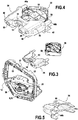
- the module is, in the embodiment, illustrated surrounded by the base 12 which forms a frame.
- the base is fixed, here secured to the housing of the lighting and / or signaling device.
- the frame forming a base in particular visible on the figure 3 , comprises two vertical uprights 28 which extend parallel or substantially parallel and which carry fixing means, some of which may be adjustable, from the base to the housing of the lighting and / or signaling device, not shown here, and it comprises an upper bar 30 and a lower bar 32 interconnecting the upper and lower ends of the vertical uprights.
- the lower bar 32 is in the illustrated case integral with the driving elements 8 and the associated male element 26, it being understood that a lower guide bearing (here not present) in rotation could be formed at this lower bar .
- a rotational guide bearing 11 formed in part by the upper bar 30 of the base 12 and in part by the additional piece 14 consisting of a support piece 34 of a fan 36.
- the upper bar substantially comprises at its center a first notch 37 which forms a first portion of the guide bearing 11.
- This first notch has a profile, in a sectional plane perpendicular to the axis of rotation AA, which presents the shape of a semicircle of defined size in adequacy with the diameter of the pin brought to cooperate with the guide bearing 11 that participates in forming this first notch.
- the driving elements 8 play the role of the lower rotational guiding elements.
- These drive elements 8 and the rotational guiding elements 10 made on the opposite amount, here higher, of the frame are arranged coaxially or substantially coaxially along an axis AA of rotation of the module. This defines an upper bearing and a lower bearing, which are opposite and aligned along the axis AA, here vertical.
- the module has on its casing 6 complementary members respectively driving elements and guide bearings of the guide elements in rotation, and in particular by the presence of a pin 24 sized to be housed in the guide bearing 11, possibly associated with stop means in position to prevent disengagement of the pin from the bearing. It may be provided a bearing to facilitate the rotation of the pin in the bearing and therefore the rotation of the module around the axis of rotation A-A, without the presence of this bearing is essential to the proper operation of the invention.
- the housing may fit on the male element 26 of the drive elements 8 via an orifice located on its lower face and having a complementary shape, for example in star section, of the male element.
- the upper rotational guiding elements i.e. the elements arranged opposite the drive elements with respect to the module, will now be described in greater detail and with particular reference to Figures 3 to 5 .
- the support piece 34 is configured so as firstly to define a guide bearing bore 11 rotating during its docking against the base 12, and secondly to at least partially receive the fan 36, so as to bear in a certain operating position. It is understood that by “support” the fan means the action to take the forces exerted on the component and transmit them to the structure of the motor vehicle. Therefore, it is the housing of the projector and not the module housing that is impacted by the particular weight of the fan, and the rotational movement of the module can be faster and more reliable.
- the support piece 34 comprises a body 38, extended at a first end 40 by a plurality of pins and barrels and extended to a second end 42 opposed by retaining tabs 44 parallel or substantially parallel to each other.
- a transverse end wall 46 carries in the illustrated example two pins 48 and two barrels 50 which extend opposite the body 38 of the support piece and which are configured to cooperate with corresponding female elements arranged on the upper bar 32 of the base. It is understood that the pins 48 allow positioning indexing of the support piece when it is brought against the upper bar of the base and that the drums allow the fixing of the support piece on the base by means of screws. or fixing pins 52 passing through these drums, thereby forming fasteners.
- the pins and the drums are arranged on the transverse end wall 46 on either side of a second notch 54 which forms a second portion of the complementary guide bearing of the first portion of the guide bearing formed by the first notch .
- the second notch 54 has a profile, in a sectional plane perpendicular to the axis of rotation AA, which has the shape of a semicircle of defined size in line with the diameter of the pin made to cooperate with the guide bearing 11 that participates in forming the second notch. It is understood from the above that the first 37 and second 54 notches have symmetrical profiles whose assembly allows the formation of a rotational guide bearing of circular section.
- the notches forming the bearing have different profiles and that one of the notches is deeper than the other notch and consists of a little more than half of the bearing, as soon as when, during the fixing of the support part against the base, the outer face of the transverse end wall being pressed against the base, the approximation of the two notches form a guide bearing around the circular periphery.
- the second notch 54 has a shoulder 55 in the extension of the upper edge of the notch. It will be understood that this shoulder can allow the housing of stop means in the position of a pawn 24 inside the guide bearing 11.
- the first notch 37 advantageously comprise a symmetrical shoulder (here not visible on the figure 3 ).
- thermoplastic polymer of the polybutylene terephthalate (PBT) type advantageously filled with glass fibers.
- this transverse end wall 46 forms the bottom wall of a cavity defined by the body 38 dug from the opposite end between the retaining lugs 44.
- This cavity makes it possible on the one hand to reduce the weight of the part, and it allows the at least partial insertion of the fan into the support part for its correct positioning before fixing.
- the retaining tabs 44 are configured to cooperate by engagement with the attachment portions of the fan 36. Additional fixing means, not shown here, may be provided to fix the position of the fan between the retaining tabs. More particularly, two first retaining tabs 44a disposed laterally on the same side of the body 38 together form a fan retaining element, the spacing of these first retaining tabs being such that the fan can in its thickness be housed between these two first legs. Two second retaining tabs 44b form laterally opposite a similar retainer.
- the retaining tabs 44 extend horizontally toward the rear of the support piece 34, so that the fan 36 is located vertically above the cooling fins 22, in the direction of the axis of rotation A. of the module.
- the fan 36 comprises a casing 56 inside which rotatable blades 58 are arranged.
- the casing has a parallelepipedal shape with an upper face 36a and an opposite lower face 36b connected to each other by lateral walls 36c. .
- the upper and lower faces, square base, are released to allow passage to the airflow disturbed by the rotation of the blades.
- bores are provided through to allow the attachment of the fan.
- the fan In the assembled position of the fan 36 and of the support piece 34, in particular visible on the figure 4 , the fan is oriented so that one of the diagonals of the square is aligned or parallel to the optical axis.
- a first top of the fan points toward the support piece, a first wedge 59 being substantially centered with respect to the body 38, and this body has a positioning finger 60 extending directly above the first corner 59 of the corresponding housing.
- the positioning finger participates in maintaining the fan relative to the support piece, to prevent the tilting of the fan.
- This arrangement of the fan corresponds to a fixing on the support piece with two lateral zones of positioning and fixing at the retaining tabs and at least one central positioning zone.
- the active surface of the fan that is to say the surface not covered by the support piece , is the most important possible.
- the thermal cooling members follow the rotational movement of the module since the support plate of the light source, carrying the cooling fins, is integral in rotation with the housing 6. And at the same time, during the pivoting movement of the module, the fan 36 remains stationary since it is integral with the base 12 fixed to the housing of the lighting and / or signaling device. It is notable that the relative displacement of the fan relative to the cooling fins contributes to the disturbance of the flow of air that is passed between the fins, which has the effect of improving the efficiency of the heat exchange with the radiator.
- the foregoing description aims to explain how the invention makes it possible to achieve the objectives that it has set itself and in particular to propose a lighting and / or signaling device that allows the realization of a directional lighting beam. , with at least one light module for which the structure of a room has been modified to give it a dual function.
- the support piece does not have a frame shape, but for example the shape of two upper and lower bars independent of one another and bearing as previously driving elements and guide elements in rotation.
Claims (14)
- Vorrichtung zur gerichteten Beleuchtung und/oder Signalisierung (1) eines Kraftfahrzeugs, umfassend zumindest:- ein Leuchtmodul (2), das um eine Achse (A-A) drehbeweglich ist;- Elemente zur Drehführung (10) dieses Leuchtmoduls (2) um die Achse (A-A);- einen Sockel (12), der mindestens einen Abschnitt der Elemente zur Drehführung (10) trägt;- einen Ventilator (36);
dadurch gekennzeichnet, dass ein Lager (11) der Elemente zur Drehführung (10) zum Teil von dem Sockel (12) und zum Teil von einem Tragteil (34) des Ventilators (36) gebildet ist. - Vorrichtung zur gerichteten Beleuchtung und/oder Signalisierung nach Anspruch 1, dadurch gekennzeichnet, dass das Führungslager (11) von einem Kreisprofilabschnitt, der auf einer Wand des Sockels (12) angeordnet ist, und von einem Kreisprofilabschnitt, der auf einer Wand des Tragteils (34) angeordnet ist, das gegenüber des Sockels angeordnet ist, gebildet ist.
- Vorrichtung zur gerichteten Beleuchtung und/oder Signalisierung nach Anspruch 2, dadurch gekennzeichnet, dass das Führungslager (11) von zwei Abschnitten äquivalenter Profile gebildet ist, die gespiegelt angeordnet sind.
- Vorrichtung zur gerichteten Beleuchtung und/oder Signalisierung nach einem der vorhergehenden Ansprüche, dadurch gekennzeichnet, dass das Tragteil (34) durch Befestigungseinrichtungen (52) am Sockel (12) befestigt ist, die beiderseits des Führungslagers (11) angeordnet sind.
- Vorrichtung zur gerichteten Beleuchtung und/oder Signalisierung nach einem der vorhergehenden Ansprüche, dadurch gekennzeichnet, dass der Sockel (12) und das Tragteil (34) aus einem selben Material gebildet sind.
- Vorrichtung zur gerichteten Beleuchtung und/oder Signalisierung nach einem der vorhergehenden Ansprüche, dadurch gekennzeichnet, dass das Tragteil (34) einen offenen Bereich zur Aufnahme eines Endes des Ventilators (36) aufweist.
- Vorrichtung zur gerichteten Beleuchtung und/oder Signalisierung nach dem vorhergehenden Anspruch, dadurch gekennzeichnet, dass der offene Bereich des Tragteils (34) gegenüber des Bereichs ausgebildet ist, der das Führungslager (11) bildet.
- Vorrichtung zur gerichteten Beleuchtung und/oder Signalisierung nach einem der vorhergehenden Ansprüche, dadurch gekennzeichnet, dass das Tragteil (34) zumindest Befestigungselemente (44) des Ventilators (36) aufweist.
- Vorrichtung zur gerichteten Beleuchtung und/oder Signalisierung nach dem vorhergehenden Anspruch, dadurch gekennzeichnet, dass die Befestigungselemente (44) des Ventilators (36) mindestens ein Paar Halteansätze (44) aufweisen, die sich gegenüber des Bereichs des Tragteils (34) erstrecken, der das Führungslager (11) bildet.
- Vorrichtung zur gerichteten Beleuchtung und/oder Signalisierung nach einem der Ansprüche 8 oder 9, dadurch gekennzeichnet, dass die Befestigungselemente (44) des Ventilators (36) seitlich im Tragteil (34) angeordnet sind, während ein Positionierungselement (60) in einer Position angeordnet ist, die bezogen auf das Tragteil mittig ist.
- Vorrichtung zur gerichteten Beleuchtung und/oder Signalisierung nach einem der vorhergehenden Ansprüche, dadurch gekennzeichnet, dass das Leuchtmodul (2) zumindest Vorrichtungen zum Aussenden von Lichtstrahlen und Kühleinrichtungen (4) aufweist.
- Vorrichtung zur gerichteten Beleuchtung und/oder Signalisierung nach dem vorhergehenden Anspruch, dadurch gekennzeichnet, dass sich der Ventilator (36) im Lot zu mindestens einem Bereich der Kühleinrichtungen (4) bezogen auf die Richtung der Drehachse (A-A) befindet.
- Vorrichtung zur gerichteten Beleuchtung und/oder Signalisierung nach einem der vorhergehenden Ansprüche, dadurch gekennzeichnet, dass sie ein Gehäuse aufweist, das mit einer Verschlussscheibe eine Aufnahme für das mindestens eine drehbewegliche Leuchtmodul (2) definiert.
- Vorrichtung zur gerichteten Beleuchtung und/oder Signalisierung nach dem vorhergehenden Anspruch, dadurch gekennzeichnet, dass der Sockel (12) auf dem Gehäuse befestigt ist.
Applications Claiming Priority (1)
| Application Number | Priority Date | Filing Date | Title |
|---|---|---|---|
| FR1654917A FR3051883B1 (fr) | 2016-05-31 | 2016-05-31 | Dispositif d'eclairage et/ou de signalisation d'un vehicule automobile |
Publications (2)
| Publication Number | Publication Date |
|---|---|
| EP3251895A1 EP3251895A1 (de) | 2017-12-06 |
| EP3251895B1 true EP3251895B1 (de) | 2019-06-26 |
Family
ID=56842847
Family Applications (1)
| Application Number | Title | Priority Date | Filing Date |
|---|---|---|---|
| EP17170689.8A Active EP3251895B1 (de) | 2016-05-31 | 2017-05-11 | Vorrichtung zur beleuchtung und/oder signalisierung für kraftfahrzeug |
Country Status (5)
| Country | Link |
|---|---|
| US (1) | US10144340B2 (de) |
| EP (1) | EP3251895B1 (de) |
| JP (1) | JP6869811B2 (de) |
| CN (1) | CN107448859B (de) |
| FR (1) | FR3051883B1 (de) |
Families Citing this family (2)
| Publication number | Priority date | Publication date | Assignee | Title |
|---|---|---|---|---|
| DE102019106492A1 (de) * | 2019-03-14 | 2020-09-17 | HELLA GmbH & Co. KGaA | Haltevorrichtung eines Lichtmoduls einer Leuchteinheit, Lichtmodul und Leuchteinheit eines Fahrzeugs |
| EP3795425A1 (de) * | 2019-09-18 | 2021-03-24 | Veoneer Sweden AB | Kameraanordnung zur montage in einem fahrzeug |
Family Cites Families (12)
| Publication number | Priority date | Publication date | Assignee | Title |
|---|---|---|---|---|
| US20070147060A1 (en) * | 2005-11-29 | 2007-06-28 | Wei-Jen Chen | Headlight driving device |
| FR2919547B1 (fr) | 2007-08-03 | 2010-01-08 | Valeo Vision | Dispositif de montage d'un module optique dans un projecteur pour vehicule automobile |
| JP2010238604A (ja) * | 2009-03-31 | 2010-10-21 | Koito Mfg Co Ltd | 発光素子モジュール化部材および灯具ユニット |
| FR2952870B1 (fr) * | 2009-11-26 | 2015-06-19 | Valeo Vision | Module d'eclairage pivotant et support correspondant pour vehicule automobile |
| JP5518533B2 (ja) * | 2010-03-12 | 2014-06-11 | 株式会社小糸製作所 | 車両用前照灯および車両用前照灯用の発光モジュール |
| CN103109131B (zh) * | 2010-07-26 | 2016-03-09 | 法雷奥照明公司 | 用于机动车辆的照明和/或信号装置的光学模块 |
| FR2965039B1 (fr) | 2010-07-26 | 2016-04-15 | Valeo Vision | Module optique de dispositif d'eclairage et/ou de signalisation d'un vehicule automobile |
| CN103206622A (zh) * | 2012-01-11 | 2013-07-17 | 欧司朗股份有限公司 | 发光装置和改型灯 |
| JP6034608B2 (ja) | 2012-07-18 | 2016-11-30 | 株式会社小糸製作所 | 車輌用前照灯 |
| JP6345052B2 (ja) * | 2013-12-20 | 2018-06-20 | 株式会社小糸製作所 | 車輌用前照灯 |
| CN105371195A (zh) * | 2014-08-26 | 2016-03-02 | 刘平 | 一种车灯 |
| CN105135320B (zh) * | 2015-09-28 | 2017-10-20 | 台州探陆泽汽配有限公司 | 一种汽车大灯 |
-
2016
- 2016-05-31 FR FR1654917A patent/FR3051883B1/fr active Active
-
2017
- 2017-05-11 EP EP17170689.8A patent/EP3251895B1/de active Active
- 2017-05-24 CN CN201710373369.0A patent/CN107448859B/zh active Active
- 2017-05-30 JP JP2017106623A patent/JP6869811B2/ja active Active
- 2017-05-31 US US15/609,817 patent/US10144340B2/en active Active
Non-Patent Citations (1)
| Title |
|---|
| None * |
Also Published As
| Publication number | Publication date |
|---|---|
| US10144340B2 (en) | 2018-12-04 |
| EP3251895A1 (de) | 2017-12-06 |
| CN107448859B (zh) | 2022-03-29 |
| US20170341564A1 (en) | 2017-11-30 |
| JP2018037399A (ja) | 2018-03-08 |
| FR3051883B1 (fr) | 2018-06-15 |
| FR3051883A1 (fr) | 2017-12-01 |
| CN107448859A (zh) | 2017-12-08 |
| JP6869811B2 (ja) | 2021-05-12 |
Similar Documents
| Publication | Publication Date | Title |
|---|---|---|
| CA2810385C (fr) | Module optique de dispositif d'eclairage et/ou de signalisation d'un vehicule automobile | |
| EP1686310B1 (de) | Kfz-Scheinwerfer mit im wesentlichen vertikaler Ausdehnung | |
| CA2810700C (fr) | Module optique de dispositif d'eclairage et/ou de signalisation d'un vehicule automobile | |
| EP2598796B1 (de) | Optisches modul einer beleuchtungs- und/oder signalisierungsvorrichtung eines kraftfahrzeuges | |
| EP3245443B1 (de) | Fahrzeugbeleuchtungsvorrichtung, in der ein lichtleiter einen anderen lichtleiter unterstützt | |
| EP1739346B1 (de) | Nebelscheinwerfervorrichtung mit Projektionslinse | |
| EP4065882B1 (de) | Lichtmodul eines kraftfahrzeugs, das mit einem optischen element ausgestattet ist | |
| FR3032778A1 (fr) | Feu de vehicule | |
| EP2966343B1 (de) | Beleuchtungsmodul für autoscheinwerfer mit positioniermittel zwischen kühlkörper und reflektor/leiterplatte | |
| EP1790906B1 (de) | Beleuchtungs- oder Signaleinrichtung für Kraftfahrzeuge | |
| EP3254019A1 (de) | Zum fahren auf der linken seite und zum fahren auf der rechten seite kompatibles fahrzeugleuchtenmodul | |
| EP3251895B1 (de) | Vorrichtung zur beleuchtung und/oder signalisierung für kraftfahrzeug | |
| FR2964723A1 (fr) | Module optique de dispositif d'eclairage et / ou de signalisation d'un vehicule automobile | |
| FR3051412A1 (fr) | Dispositif d’eclairage et/ou de signalisation pour vehicule automobile destine a etre implante dans un element de carrosserie | |
| FR3064721B1 (fr) | Dispositif lumineux avec radiateur traversant le boitier | |
| WO2024089286A1 (fr) | Dispositif d'éclairage pour un véhicule automobile | |
| WO2024089285A1 (fr) | Dispositif d'éclairage pour un véhicule automobile | |
| EP3221185B1 (de) | Leuchteinheit für ein fahrzeug und dazugehöriges fahrzeug | |
| WO2022129617A1 (fr) | Dispositif lumineux pour véhicule automobile | |
| FR2964724A1 (fr) | Module optique de dispositif d'eclairage et/ou de signalisation d'un vehicule automobile. | |
| FR3138789A1 (fr) | Projecteur á coupure et étendu verticalement pour véhicule automobile | |
| FR2911664A1 (fr) | Module d'eclairage ou de signalisation d'aspect ameliore |
Legal Events
| Date | Code | Title | Description |
|---|---|---|---|
| PUAI | Public reference made under article 153(3) epc to a published international application that has entered the european phase |
Free format text: ORIGINAL CODE: 0009012 |
|
| STAA | Information on the status of an ep patent application or granted ep patent |
Free format text: STATUS: THE APPLICATION HAS BEEN PUBLISHED |
|
| AK | Designated contracting states |
Kind code of ref document: A1 Designated state(s): AL AT BE BG CH CY CZ DE DK EE ES FI FR GB GR HR HU IE IS IT LI LT LU LV MC MK MT NL NO PL PT RO RS SE SI SK SM TR |
|
| AX | Request for extension of the european patent |
Extension state: BA ME |
|
| STAA | Information on the status of an ep patent application or granted ep patent |
Free format text: STATUS: REQUEST FOR EXAMINATION WAS MADE |
|
| 17P | Request for examination filed |
Effective date: 20180601 |
|
| RBV | Designated contracting states (corrected) |
Designated state(s): AL AT BE BG CH CY CZ DE DK EE ES FI FR GB GR HR HU IE IS IT LI LT LU LV MC MK MT NL NO PL PT RO RS SE SI SK SM TR |
|
| REG | Reference to a national code |
Ref country code: DE Ref legal event code: R079 Ref document number: 602017004776 Country of ref document: DE Free format text: PREVIOUS MAIN CLASS: B60Q0001060000 Ipc: B60Q0001076000 |
|
| RIC1 | Information provided on ipc code assigned before grant |
Ipc: F21S 45/43 20180101ALI20181214BHEP Ipc: B60Q 1/076 20060101AFI20181214BHEP Ipc: F21S 45/49 20180101ALI20181214BHEP |
|
| GRAP | Despatch of communication of intention to grant a patent |
Free format text: ORIGINAL CODE: EPIDOSNIGR1 |
|
| STAA | Information on the status of an ep patent application or granted ep patent |
Free format text: STATUS: GRANT OF PATENT IS INTENDED |
|
| INTG | Intention to grant announced |
Effective date: 20190129 |
|
| GRAS | Grant fee paid |
Free format text: ORIGINAL CODE: EPIDOSNIGR3 |
|
| GRAA | (expected) grant |
Free format text: ORIGINAL CODE: 0009210 |
|
| STAA | Information on the status of an ep patent application or granted ep patent |
Free format text: STATUS: THE PATENT HAS BEEN GRANTED |
|
| AK | Designated contracting states |
Kind code of ref document: B1 Designated state(s): AL AT BE BG CH CY CZ DE DK EE ES FI FR GB GR HR HU IE IS IT LI LT LU LV MC MK MT NL NO PL PT RO RS SE SI SK SM TR |
|
| REG | Reference to a national code |
Ref country code: GB Ref legal event code: FG4D Free format text: NOT ENGLISH |
|
| REG | Reference to a national code |
Ref country code: CH Ref legal event code: EP |
|
| REG | Reference to a national code |
Ref country code: AT Ref legal event code: REF Ref document number: 1147905 Country of ref document: AT Kind code of ref document: T Effective date: 20190715 |
|
| REG | Reference to a national code |
Ref country code: DE Ref legal event code: R096 Ref document number: 602017004776 Country of ref document: DE |
|
| REG | Reference to a national code |
Ref country code: IE Ref legal event code: FG4D Free format text: LANGUAGE OF EP DOCUMENT: FRENCH |
|
| REG | Reference to a national code |
Ref country code: NL Ref legal event code: FP |
|
| PG25 | Lapsed in a contracting state [announced via postgrant information from national office to epo] |
Ref country code: SE Free format text: LAPSE BECAUSE OF FAILURE TO SUBMIT A TRANSLATION OF THE DESCRIPTION OR TO PAY THE FEE WITHIN THE PRESCRIBED TIME-LIMIT Effective date: 20190626 Ref country code: LT Free format text: LAPSE BECAUSE OF FAILURE TO SUBMIT A TRANSLATION OF THE DESCRIPTION OR TO PAY THE FEE WITHIN THE PRESCRIBED TIME-LIMIT Effective date: 20190626 Ref country code: NO Free format text: LAPSE BECAUSE OF FAILURE TO SUBMIT A TRANSLATION OF THE DESCRIPTION OR TO PAY THE FEE WITHIN THE PRESCRIBED TIME-LIMIT Effective date: 20190926 Ref country code: AL Free format text: LAPSE BECAUSE OF FAILURE TO SUBMIT A TRANSLATION OF THE DESCRIPTION OR TO PAY THE FEE WITHIN THE PRESCRIBED TIME-LIMIT Effective date: 20190626 Ref country code: HR Free format text: LAPSE BECAUSE OF FAILURE TO SUBMIT A TRANSLATION OF THE DESCRIPTION OR TO PAY THE FEE WITHIN THE PRESCRIBED TIME-LIMIT Effective date: 20190626 Ref country code: FI Free format text: LAPSE BECAUSE OF FAILURE TO SUBMIT A TRANSLATION OF THE DESCRIPTION OR TO PAY THE FEE WITHIN THE PRESCRIBED TIME-LIMIT Effective date: 20190626 |
|
| REG | Reference to a national code |
Ref country code: LT Ref legal event code: MG4D |
|
| PG25 | Lapsed in a contracting state [announced via postgrant information from national office to epo] |
Ref country code: GR Free format text: LAPSE BECAUSE OF FAILURE TO SUBMIT A TRANSLATION OF THE DESCRIPTION OR TO PAY THE FEE WITHIN THE PRESCRIBED TIME-LIMIT Effective date: 20190927 Ref country code: BG Free format text: LAPSE BECAUSE OF FAILURE TO SUBMIT A TRANSLATION OF THE DESCRIPTION OR TO PAY THE FEE WITHIN THE PRESCRIBED TIME-LIMIT Effective date: 20190926 Ref country code: RS Free format text: LAPSE BECAUSE OF FAILURE TO SUBMIT A TRANSLATION OF THE DESCRIPTION OR TO PAY THE FEE WITHIN THE PRESCRIBED TIME-LIMIT Effective date: 20190626 Ref country code: LV Free format text: LAPSE BECAUSE OF FAILURE TO SUBMIT A TRANSLATION OF THE DESCRIPTION OR TO PAY THE FEE WITHIN THE PRESCRIBED TIME-LIMIT Effective date: 20190626 |
|
| REG | Reference to a national code |
Ref country code: AT Ref legal event code: MK05 Ref document number: 1147905 Country of ref document: AT Kind code of ref document: T Effective date: 20190626 |
|
| PG25 | Lapsed in a contracting state [announced via postgrant information from national office to epo] |
Ref country code: AT Free format text: LAPSE BECAUSE OF FAILURE TO SUBMIT A TRANSLATION OF THE DESCRIPTION OR TO PAY THE FEE WITHIN THE PRESCRIBED TIME-LIMIT Effective date: 20190626 Ref country code: EE Free format text: LAPSE BECAUSE OF FAILURE TO SUBMIT A TRANSLATION OF THE DESCRIPTION OR TO PAY THE FEE WITHIN THE PRESCRIBED TIME-LIMIT Effective date: 20190626 Ref country code: SK Free format text: LAPSE BECAUSE OF FAILURE TO SUBMIT A TRANSLATION OF THE DESCRIPTION OR TO PAY THE FEE WITHIN THE PRESCRIBED TIME-LIMIT Effective date: 20190626 Ref country code: PT Free format text: LAPSE BECAUSE OF FAILURE TO SUBMIT A TRANSLATION OF THE DESCRIPTION OR TO PAY THE FEE WITHIN THE PRESCRIBED TIME-LIMIT Effective date: 20191028 Ref country code: RO Free format text: LAPSE BECAUSE OF FAILURE TO SUBMIT A TRANSLATION OF THE DESCRIPTION OR TO PAY THE FEE WITHIN THE PRESCRIBED TIME-LIMIT Effective date: 20190626 Ref country code: CZ Free format text: LAPSE BECAUSE OF FAILURE TO SUBMIT A TRANSLATION OF THE DESCRIPTION OR TO PAY THE FEE WITHIN THE PRESCRIBED TIME-LIMIT Effective date: 20190626 |
|
| PG25 | Lapsed in a contracting state [announced via postgrant information from national office to epo] |
Ref country code: IS Free format text: LAPSE BECAUSE OF FAILURE TO SUBMIT A TRANSLATION OF THE DESCRIPTION OR TO PAY THE FEE WITHIN THE PRESCRIBED TIME-LIMIT Effective date: 20191026 Ref country code: ES Free format text: LAPSE BECAUSE OF FAILURE TO SUBMIT A TRANSLATION OF THE DESCRIPTION OR TO PAY THE FEE WITHIN THE PRESCRIBED TIME-LIMIT Effective date: 20190626 Ref country code: SM Free format text: LAPSE BECAUSE OF FAILURE TO SUBMIT A TRANSLATION OF THE DESCRIPTION OR TO PAY THE FEE WITHIN THE PRESCRIBED TIME-LIMIT Effective date: 20190626 Ref country code: IT Free format text: LAPSE BECAUSE OF FAILURE TO SUBMIT A TRANSLATION OF THE DESCRIPTION OR TO PAY THE FEE WITHIN THE PRESCRIBED TIME-LIMIT Effective date: 20190626 |
|
| PG25 | Lapsed in a contracting state [announced via postgrant information from national office to epo] |
Ref country code: TR Free format text: LAPSE BECAUSE OF FAILURE TO SUBMIT A TRANSLATION OF THE DESCRIPTION OR TO PAY THE FEE WITHIN THE PRESCRIBED TIME-LIMIT Effective date: 20190626 |
|
| PG25 | Lapsed in a contracting state [announced via postgrant information from national office to epo] |
Ref country code: PL Free format text: LAPSE BECAUSE OF FAILURE TO SUBMIT A TRANSLATION OF THE DESCRIPTION OR TO PAY THE FEE WITHIN THE PRESCRIBED TIME-LIMIT Effective date: 20190626 Ref country code: DK Free format text: LAPSE BECAUSE OF FAILURE TO SUBMIT A TRANSLATION OF THE DESCRIPTION OR TO PAY THE FEE WITHIN THE PRESCRIBED TIME-LIMIT Effective date: 20190626 |
|
| PG25 | Lapsed in a contracting state [announced via postgrant information from national office to epo] |
Ref country code: IS Free format text: LAPSE BECAUSE OF FAILURE TO SUBMIT A TRANSLATION OF THE DESCRIPTION OR TO PAY THE FEE WITHIN THE PRESCRIBED TIME-LIMIT Effective date: 20200320 |
|
| REG | Reference to a national code |
Ref country code: DE Ref legal event code: R097 Ref document number: 602017004776 Country of ref document: DE |
|
| PLBE | No opposition filed within time limit |
Free format text: ORIGINAL CODE: 0009261 |
|
| STAA | Information on the status of an ep patent application or granted ep patent |
Free format text: STATUS: NO OPPOSITION FILED WITHIN TIME LIMIT |
|
| PG2D | Information on lapse in contracting state deleted |
Ref country code: IS |
|
| 26N | No opposition filed |
Effective date: 20200603 |
|
| PG25 | Lapsed in a contracting state [announced via postgrant information from national office to epo] |
Ref country code: SI Free format text: LAPSE BECAUSE OF FAILURE TO SUBMIT A TRANSLATION OF THE DESCRIPTION OR TO PAY THE FEE WITHIN THE PRESCRIBED TIME-LIMIT Effective date: 20190626 |
|
| PG25 | Lapsed in a contracting state [announced via postgrant information from national office to epo] |
Ref country code: LI Free format text: LAPSE BECAUSE OF NON-PAYMENT OF DUE FEES Effective date: 20200531 Ref country code: MC Free format text: LAPSE BECAUSE OF FAILURE TO SUBMIT A TRANSLATION OF THE DESCRIPTION OR TO PAY THE FEE WITHIN THE PRESCRIBED TIME-LIMIT Effective date: 20190626 Ref country code: CH Free format text: LAPSE BECAUSE OF NON-PAYMENT OF DUE FEES Effective date: 20200531 |
|
| REG | Reference to a national code |
Ref country code: BE Ref legal event code: MM Effective date: 20200531 |
|
| PG25 | Lapsed in a contracting state [announced via postgrant information from national office to epo] |
Ref country code: LU Free format text: LAPSE BECAUSE OF NON-PAYMENT OF DUE FEES Effective date: 20200511 |
|
| PG25 | Lapsed in a contracting state [announced via postgrant information from national office to epo] |
Ref country code: IE Free format text: LAPSE BECAUSE OF NON-PAYMENT OF DUE FEES Effective date: 20200511 |
|
| PG25 | Lapsed in a contracting state [announced via postgrant information from national office to epo] |
Ref country code: BE Free format text: LAPSE BECAUSE OF NON-PAYMENT OF DUE FEES Effective date: 20200531 |
|
| GBPC | Gb: european patent ceased through non-payment of renewal fee |
Effective date: 20210511 |
|
| PG25 | Lapsed in a contracting state [announced via postgrant information from national office to epo] |
Ref country code: GB Free format text: LAPSE BECAUSE OF NON-PAYMENT OF DUE FEES Effective date: 20210511 |
|
| PG25 | Lapsed in a contracting state [announced via postgrant information from national office to epo] |
Ref country code: MT Free format text: LAPSE BECAUSE OF FAILURE TO SUBMIT A TRANSLATION OF THE DESCRIPTION OR TO PAY THE FEE WITHIN THE PRESCRIBED TIME-LIMIT Effective date: 20190626 Ref country code: CY Free format text: LAPSE BECAUSE OF FAILURE TO SUBMIT A TRANSLATION OF THE DESCRIPTION OR TO PAY THE FEE WITHIN THE PRESCRIBED TIME-LIMIT Effective date: 20190626 |
|
| PG25 | Lapsed in a contracting state [announced via postgrant information from national office to epo] |
Ref country code: MK Free format text: LAPSE BECAUSE OF FAILURE TO SUBMIT A TRANSLATION OF THE DESCRIPTION OR TO PAY THE FEE WITHIN THE PRESCRIBED TIME-LIMIT Effective date: 20190626 |
|
| PGFP | Annual fee paid to national office [announced via postgrant information from national office to epo] |
Ref country code: NL Payment date: 20230427 Year of fee payment: 7 |
|
| P01 | Opt-out of the competence of the unified patent court (upc) registered |
Effective date: 20230528 |
|
| PGFP | Annual fee paid to national office [announced via postgrant information from national office to epo] |
Ref country code: FR Payment date: 20230523 Year of fee payment: 7 Ref country code: DE Payment date: 20230510 Year of fee payment: 7 |