EP3251895B1 - Lighting and/or signalling device for a motor vehicle - Google Patents
Lighting and/or signalling device for a motor vehicle Download PDFInfo
- Publication number
- EP3251895B1 EP3251895B1 EP17170689.8A EP17170689A EP3251895B1 EP 3251895 B1 EP3251895 B1 EP 3251895B1 EP 17170689 A EP17170689 A EP 17170689A EP 3251895 B1 EP3251895 B1 EP 3251895B1
- Authority
- EP
- European Patent Office
- Prior art keywords
- signalling device
- fan
- base
- directional lighting
- support piece
- Prior art date
- Legal status (The legal status is an assumption and is not a legal conclusion. Google has not performed a legal analysis and makes no representation as to the accuracy of the status listed.)
- Active
Links
Images
Classifications
-
- F—MECHANICAL ENGINEERING; LIGHTING; HEATING; WEAPONS; BLASTING
- F21—LIGHTING
- F21V—FUNCTIONAL FEATURES OR DETAILS OF LIGHTING DEVICES OR SYSTEMS THEREOF; STRUCTURAL COMBINATIONS OF LIGHTING DEVICES WITH OTHER ARTICLES, NOT OTHERWISE PROVIDED FOR
- F21V17/00—Fastening of component parts of lighting devices, e.g. shades, globes, refractors, reflectors, filters, screens, grids or protective cages
- F21V17/10—Fastening of component parts of lighting devices, e.g. shades, globes, refractors, reflectors, filters, screens, grids or protective cages characterised by specific fastening means or way of fastening
- F21V17/104—Fastening of component parts of lighting devices, e.g. shades, globes, refractors, reflectors, filters, screens, grids or protective cages characterised by specific fastening means or way of fastening using feather joints, e.g. tongues and grooves, with or without friction
-
- F—MECHANICAL ENGINEERING; LIGHTING; HEATING; WEAPONS; BLASTING
- F21—LIGHTING
- F21S—NON-PORTABLE LIGHTING DEVICES; SYSTEMS THEREOF; VEHICLE LIGHTING DEVICES SPECIALLY ADAPTED FOR VEHICLE EXTERIORS
- F21S45/00—Arrangements within vehicle lighting devices specially adapted for vehicle exteriors, for purposes other than emission or distribution of light
- F21S45/40—Cooling of lighting devices
- F21S45/42—Forced cooling
- F21S45/43—Forced cooling using gas
-
- B—PERFORMING OPERATIONS; TRANSPORTING
- B60—VEHICLES IN GENERAL
- B60Q—ARRANGEMENT OF SIGNALLING OR LIGHTING DEVICES, THE MOUNTING OR SUPPORTING THEREOF OR CIRCUITS THEREFOR, FOR VEHICLES IN GENERAL
- B60Q1/00—Arrangement of optical signalling or lighting devices, the mounting or supporting thereof or circuits therefor
- B60Q1/02—Arrangement of optical signalling or lighting devices, the mounting or supporting thereof or circuits therefor the devices being primarily intended to illuminate the way ahead or to illuminate other areas of way or environments
- B60Q1/04—Arrangement of optical signalling or lighting devices, the mounting or supporting thereof or circuits therefor the devices being primarily intended to illuminate the way ahead or to illuminate other areas of way or environments the devices being headlights
- B60Q1/0408—Arrangement of optical signalling or lighting devices, the mounting or supporting thereof or circuits therefor the devices being primarily intended to illuminate the way ahead or to illuminate other areas of way or environments the devices being headlights built into the vehicle body, e.g. details concerning the mounting of the headlamps on the vehicle body
- B60Q1/0425—Arrangement of optical signalling or lighting devices, the mounting or supporting thereof or circuits therefor the devices being primarily intended to illuminate the way ahead or to illuminate other areas of way or environments the devices being headlights built into the vehicle body, e.g. details concerning the mounting of the headlamps on the vehicle body the housing being swivel mounted on the vehicle body
-
- B—PERFORMING OPERATIONS; TRANSPORTING
- B60—VEHICLES IN GENERAL
- B60Q—ARRANGEMENT OF SIGNALLING OR LIGHTING DEVICES, THE MOUNTING OR SUPPORTING THEREOF OR CIRCUITS THEREFOR, FOR VEHICLES IN GENERAL
- B60Q1/00—Arrangement of optical signalling or lighting devices, the mounting or supporting thereof or circuits therefor
- B60Q1/02—Arrangement of optical signalling or lighting devices, the mounting or supporting thereof or circuits therefor the devices being primarily intended to illuminate the way ahead or to illuminate other areas of way or environments
- B60Q1/04—Arrangement of optical signalling or lighting devices, the mounting or supporting thereof or circuits therefor the devices being primarily intended to illuminate the way ahead or to illuminate other areas of way or environments the devices being headlights
- B60Q1/06—Arrangement of optical signalling or lighting devices, the mounting or supporting thereof or circuits therefor the devices being primarily intended to illuminate the way ahead or to illuminate other areas of way or environments the devices being headlights adjustable, e.g. remotely-controlled from inside vehicle
- B60Q1/076—Arrangement of optical signalling or lighting devices, the mounting or supporting thereof or circuits therefor the devices being primarily intended to illuminate the way ahead or to illuminate other areas of way or environments the devices being headlights adjustable, e.g. remotely-controlled from inside vehicle by electrical means including means to transmit the movements, e.g. shafts or joints
-
- B—PERFORMING OPERATIONS; TRANSPORTING
- B60—VEHICLES IN GENERAL
- B60Q—ARRANGEMENT OF SIGNALLING OR LIGHTING DEVICES, THE MOUNTING OR SUPPORTING THEREOF OR CIRCUITS THEREFOR, FOR VEHICLES IN GENERAL
- B60Q1/00—Arrangement of optical signalling or lighting devices, the mounting or supporting thereof or circuits therefor
- B60Q1/02—Arrangement of optical signalling or lighting devices, the mounting or supporting thereof or circuits therefor the devices being primarily intended to illuminate the way ahead or to illuminate other areas of way or environments
- B60Q1/04—Arrangement of optical signalling or lighting devices, the mounting or supporting thereof or circuits therefor the devices being primarily intended to illuminate the way ahead or to illuminate other areas of way or environments the devices being headlights
- B60Q1/06—Arrangement of optical signalling or lighting devices, the mounting or supporting thereof or circuits therefor the devices being primarily intended to illuminate the way ahead or to illuminate other areas of way or environments the devices being headlights adjustable, e.g. remotely-controlled from inside vehicle
- B60Q1/08—Arrangement of optical signalling or lighting devices, the mounting or supporting thereof or circuits therefor the devices being primarily intended to illuminate the way ahead or to illuminate other areas of way or environments the devices being headlights adjustable, e.g. remotely-controlled from inside vehicle automatically
- B60Q1/12—Arrangement of optical signalling or lighting devices, the mounting or supporting thereof or circuits therefor the devices being primarily intended to illuminate the way ahead or to illuminate other areas of way or environments the devices being headlights adjustable, e.g. remotely-controlled from inside vehicle automatically due to steering position
- B60Q1/122—Arrangement of optical signalling or lighting devices, the mounting or supporting thereof or circuits therefor the devices being primarily intended to illuminate the way ahead or to illuminate other areas of way or environments the devices being headlights adjustable, e.g. remotely-controlled from inside vehicle automatically due to steering position with electrical actuating means
-
- F—MECHANICAL ENGINEERING; LIGHTING; HEATING; WEAPONS; BLASTING
- F21—LIGHTING
- F21S—NON-PORTABLE LIGHTING DEVICES; SYSTEMS THEREOF; VEHICLE LIGHTING DEVICES SPECIALLY ADAPTED FOR VEHICLE EXTERIORS
- F21S41/00—Illuminating devices specially adapted for vehicle exteriors, e.g. headlamps
- F21S41/20—Illuminating devices specially adapted for vehicle exteriors, e.g. headlamps characterised by refractors, transparent cover plates, light guides or filters
- F21S41/29—Attachment thereof
-
- F—MECHANICAL ENGINEERING; LIGHTING; HEATING; WEAPONS; BLASTING
- F21—LIGHTING
- F21S—NON-PORTABLE LIGHTING DEVICES; SYSTEMS THEREOF; VEHICLE LIGHTING DEVICES SPECIALLY ADAPTED FOR VEHICLE EXTERIORS
- F21S45/00—Arrangements within vehicle lighting devices specially adapted for vehicle exteriors, for purposes other than emission or distribution of light
- F21S45/40—Cooling of lighting devices
- F21S45/49—Attachment of the cooling means
-
- F—MECHANICAL ENGINEERING; LIGHTING; HEATING; WEAPONS; BLASTING
- F21—LIGHTING
- F21V—FUNCTIONAL FEATURES OR DETAILS OF LIGHTING DEVICES OR SYSTEMS THEREOF; STRUCTURAL COMBINATIONS OF LIGHTING DEVICES WITH OTHER ARTICLES, NOT OTHERWISE PROVIDED FOR
- F21V15/00—Protecting lighting devices from damage
- F21V15/02—Cages
-
- F—MECHANICAL ENGINEERING; LIGHTING; HEATING; WEAPONS; BLASTING
- F21—LIGHTING
- F21V—FUNCTIONAL FEATURES OR DETAILS OF LIGHTING DEVICES OR SYSTEMS THEREOF; STRUCTURAL COMBINATIONS OF LIGHTING DEVICES WITH OTHER ARTICLES, NOT OTHERWISE PROVIDED FOR
- F21V17/00—Fastening of component parts of lighting devices, e.g. shades, globes, refractors, reflectors, filters, screens, grids or protective cages
- F21V17/10—Fastening of component parts of lighting devices, e.g. shades, globes, refractors, reflectors, filters, screens, grids or protective cages characterised by specific fastening means or way of fastening
- F21V17/12—Fastening of component parts of lighting devices, e.g. shades, globes, refractors, reflectors, filters, screens, grids or protective cages characterised by specific fastening means or way of fastening by screwing
-
- F—MECHANICAL ENGINEERING; LIGHTING; HEATING; WEAPONS; BLASTING
- F21—LIGHTING
- F21V—FUNCTIONAL FEATURES OR DETAILS OF LIGHTING DEVICES OR SYSTEMS THEREOF; STRUCTURAL COMBINATIONS OF LIGHTING DEVICES WITH OTHER ARTICLES, NOT OTHERWISE PROVIDED FOR
- F21V21/00—Supporting, suspending, or attaching arrangements for lighting devices; Hand grips
-
- F—MECHANICAL ENGINEERING; LIGHTING; HEATING; WEAPONS; BLASTING
- F21—LIGHTING
- F21V—FUNCTIONAL FEATURES OR DETAILS OF LIGHTING DEVICES OR SYSTEMS THEREOF; STRUCTURAL COMBINATIONS OF LIGHTING DEVICES WITH OTHER ARTICLES, NOT OTHERWISE PROVIDED FOR
- F21V29/00—Protecting lighting devices from thermal damage; Cooling or heating arrangements specially adapted for lighting devices or systems
- F21V29/50—Cooling arrangements
- F21V29/60—Cooling arrangements characterised by the use of a forced flow of gas, e.g. air
- F21V29/67—Cooling arrangements characterised by the use of a forced flow of gas, e.g. air characterised by the arrangement of fans
-
- F—MECHANICAL ENGINEERING; LIGHTING; HEATING; WEAPONS; BLASTING
- F21—LIGHTING
- F21V—FUNCTIONAL FEATURES OR DETAILS OF LIGHTING DEVICES OR SYSTEMS THEREOF; STRUCTURAL COMBINATIONS OF LIGHTING DEVICES WITH OTHER ARTICLES, NOT OTHERWISE PROVIDED FOR
- F21V5/00—Refractors for light sources
- F21V5/04—Refractors for light sources of lens shape
-
- B—PERFORMING OPERATIONS; TRANSPORTING
- B60—VEHICLES IN GENERAL
- B60Q—ARRANGEMENT OF SIGNALLING OR LIGHTING DEVICES, THE MOUNTING OR SUPPORTING THEREOF OR CIRCUITS THEREFOR, FOR VEHICLES IN GENERAL
- B60Q1/00—Arrangement of optical signalling or lighting devices, the mounting or supporting thereof or circuits therefor
- B60Q1/02—Arrangement of optical signalling or lighting devices, the mounting or supporting thereof or circuits therefor the devices being primarily intended to illuminate the way ahead or to illuminate other areas of way or environments
- B60Q1/04—Arrangement of optical signalling or lighting devices, the mounting or supporting thereof or circuits therefor the devices being primarily intended to illuminate the way ahead or to illuminate other areas of way or environments the devices being headlights
- B60Q1/06—Arrangement of optical signalling or lighting devices, the mounting or supporting thereof or circuits therefor the devices being primarily intended to illuminate the way ahead or to illuminate other areas of way or environments the devices being headlights adjustable, e.g. remotely-controlled from inside vehicle
- B60Q1/08—Arrangement of optical signalling or lighting devices, the mounting or supporting thereof or circuits therefor the devices being primarily intended to illuminate the way ahead or to illuminate other areas of way or environments the devices being headlights adjustable, e.g. remotely-controlled from inside vehicle automatically
- B60Q1/12—Arrangement of optical signalling or lighting devices, the mounting or supporting thereof or circuits therefor the devices being primarily intended to illuminate the way ahead or to illuminate other areas of way or environments the devices being headlights adjustable, e.g. remotely-controlled from inside vehicle automatically due to steering position
-
- F—MECHANICAL ENGINEERING; LIGHTING; HEATING; WEAPONS; BLASTING
- F21—LIGHTING
- F21S—NON-PORTABLE LIGHTING DEVICES; SYSTEMS THEREOF; VEHICLE LIGHTING DEVICES SPECIALLY ADAPTED FOR VEHICLE EXTERIORS
- F21S41/00—Illuminating devices specially adapted for vehicle exteriors, e.g. headlamps
- F21S41/10—Illuminating devices specially adapted for vehicle exteriors, e.g. headlamps characterised by the light source
- F21S41/14—Illuminating devices specially adapted for vehicle exteriors, e.g. headlamps characterised by the light source characterised by the type of light source
- F21S41/141—Light emitting diodes [LED]
Definitions
- the present invention relates to a lighting and / or signaling device of a motor vehicle, and more particularly to a rotary light module, adapted to pivot according to the path followed by the vehicle, equipping such a device.
- a motor vehicle is equipped with projectors, or headlights, forming lighting and / or signaling devices intended to illuminate the road in front of the vehicle, at night or in the event of reduced brightness, by a global light beam.
- projectors or headlights, forming lighting and / or signaling devices intended to illuminate the road in front of the vehicle, at night or in the event of reduced brightness, by a global light beam.
- These projectors, a left projector and a straight projector comprise one or more light modules adapted to generate and direct an intermediate light beam whose addition forms said overall light beam.
- DBL Dynamic Bending Light
- the purpose of such a function is to dynamically illuminate turns when the vehicle is turning.
- the field of the invention is, in general, that of projectors for motor vehicles performing the function of directional lighting.
- the document FR2965039 discloses a light module adapted to be mounted in rotation in a housing of a lighting device via a fixed base.
- the base comprises, on the one hand, motorized drive means for rotating the module and, on the other hand, at least one guide bearing in rotation of the module, opposite the motorized means with respect to the module, in order to ensure the rotation thereof around the drive axis.
- the rotational guiding bearing is constituted in particular by a half-shell attached to the base for gripping a peg of shape and corresponding dimensions embedded on the module, and more particularly on a module envelope also allowing the setting in position and fixing a light source and an associated projection optical system, and the positioning and the fixing of cooling members, among which a radiator and a fan.
- the envelope of the module is configured to cooperate with the drive elements and guide rotation carried by the base, and the rotation of this envelope generates the rotation of each of the component parts of the module. It is understood that the large number of inserts on the envelope increases the weight of the module, which can penalize the rotation of the latter for directional lighting, and which may require oversizing of the rotating drive elements. of the module.
- the invention proposes a lighting and / or directional signaling device for a motor vehicle comprising a light module that can be rotated about an axis, that is to say say able to produce at least one orientable light beam.
- the axis of rotation is supported by a base bearing guide elements in rotation of the module about the axis.
- a bearing of the rotating guide elements is formed in part by the base and partly by a support part of a fan.
- the module can thus be mounted in rotation in the lighting and / or signaling device of a motor vehicle so as to orient the optical axis of the module according to the curves negotiated by the vehicle.
- the rotation of the light module relative to the device is provided by the base, in particular fixed relative to a housing of the device.
- the geometry of the base can be defined so that it can surround the light module.
- the light module cooperates with the base by means of rotating guide elements and drive elements, which can also be reported on the base implement this rotation.
- the rotational guiding elements and the driving elements may be coaxial along an axis, in particular a vertical axis, defining the axis of rotation of the module.
- the rotational guiding elements and the driving elements can respectively define a guide bearing upper and a lower guide bearing, which are opposite and aligned along the axis of rotation of the light module.
- the light module may, for example, engage with the drive elements via an orifice and cooperate with the rotating guide members via a pivot connection.
- front and back will be understood with respect to the main direction of ray emission at the output of the light module, along the optical axis of the module, and in the direction of transmission from these rays from the back to the front.
- references relating to a “up / down” positioning of the components and / or the structural elements of a component will be understood with respect to an operating position of the module in the vehicle.
- a lighting and / or signaling device 1 configured according to the invention to participate in a directional lighting function comprises at least one light module 2 as will be described by way of example below.
- This at least one light module can in particular be housed, alone or in the vicinity of other light modules, in a housing of the device closed by a closure glass.
- a light module 2 comprises light emitting devices, cooling members 4 and a housing 6 configured to support all of these elements.
- the module is rotatable in that the housing cooperates with drive elements 8 provided for rotating the housing and in particular the emission devices about an axis of rotation AA, the rotation being facilitated by at least elements of 10.
- a guide bearing 11 of these rotational guiding elements 10 is formed by the cooperation of a portion of a base 12 with an additional piece 14 attached to this part of the base.
- the light module 2 is pivotally mounted about the axis of rotation AA relative to the base 12, furthermore fixed on the housing, between two extreme angular positions, defined by the bulk of the device and the stop of the module against the walls of the base and which, depending on the path of the vehicle, a right / left orientation of the light beam produced by the lighting and / or signaling device.
- the light-ray emitting devices comprise at least one light source (not visible) and an optical system for shaping the rays, here comprising a reflector (not visible) and a lens 16.
- the cooling members 4 comprise in particular a heat exchanger or radiator 18, which has a support plate 20, on which is disposed the at least one light source, extended towards the rear of the module by a succession of cooling fins 22.
- the heat generated by the light source, and in particular by the associated printed circuit board when the light source is a light-emitting diode, is removed from the module via the support plate and the cooling fins.
- the casing 6 is configured to at least partially cover each of the emitting devices and cooling members of the module, and to ensure their correct positioning in relation to each other.
- the casing is formed of two lower shells 6a and 6b placed opposite and fixed, but it will be understood that the number of light sources and reflectors, here one of each for each shell, may vary so only one hull is needed to form the crankcase.
- Each shell extends longitudinally, that is to say in the direction of the optical axis of the module, from the radiator 18 to the lens 16.
- the upper shell 6b comprises a pin 24 arranged projecting from its upper face to cooperate with the base 12 and form guide elements in rotation of the module, while the lower shell has a bore dug since its lower face whose section forms a complementary recess of a male element 26 of the drive elements 8 carried by the base.
- the module is, in the embodiment, illustrated surrounded by the base 12 which forms a frame.
- the base is fixed, here secured to the housing of the lighting and / or signaling device.
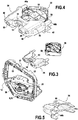
- the frame forming a base in particular visible on the figure 3 , comprises two vertical uprights 28 which extend parallel or substantially parallel and which carry fixing means, some of which may be adjustable, from the base to the housing of the lighting and / or signaling device, not shown here, and it comprises an upper bar 30 and a lower bar 32 interconnecting the upper and lower ends of the vertical uprights.
- the lower bar 32 is in the illustrated case integral with the driving elements 8 and the associated male element 26, it being understood that a lower guide bearing (here not present) in rotation could be formed at this lower bar .
- a rotational guide bearing 11 formed in part by the upper bar 30 of the base 12 and in part by the additional piece 14 consisting of a support piece 34 of a fan 36.
- the upper bar substantially comprises at its center a first notch 37 which forms a first portion of the guide bearing 11.
- This first notch has a profile, in a sectional plane perpendicular to the axis of rotation AA, which presents the shape of a semicircle of defined size in adequacy with the diameter of the pin brought to cooperate with the guide bearing 11 that participates in forming this first notch.
- the driving elements 8 play the role of the lower rotational guiding elements.
- These drive elements 8 and the rotational guiding elements 10 made on the opposite amount, here higher, of the frame are arranged coaxially or substantially coaxially along an axis AA of rotation of the module. This defines an upper bearing and a lower bearing, which are opposite and aligned along the axis AA, here vertical.
- the module has on its casing 6 complementary members respectively driving elements and guide bearings of the guide elements in rotation, and in particular by the presence of a pin 24 sized to be housed in the guide bearing 11, possibly associated with stop means in position to prevent disengagement of the pin from the bearing. It may be provided a bearing to facilitate the rotation of the pin in the bearing and therefore the rotation of the module around the axis of rotation A-A, without the presence of this bearing is essential to the proper operation of the invention.
- the housing may fit on the male element 26 of the drive elements 8 via an orifice located on its lower face and having a complementary shape, for example in star section, of the male element.
- the upper rotational guiding elements i.e. the elements arranged opposite the drive elements with respect to the module, will now be described in greater detail and with particular reference to Figures 3 to 5 .
- the support piece 34 is configured so as firstly to define a guide bearing bore 11 rotating during its docking against the base 12, and secondly to at least partially receive the fan 36, so as to bear in a certain operating position. It is understood that by “support” the fan means the action to take the forces exerted on the component and transmit them to the structure of the motor vehicle. Therefore, it is the housing of the projector and not the module housing that is impacted by the particular weight of the fan, and the rotational movement of the module can be faster and more reliable.
- the support piece 34 comprises a body 38, extended at a first end 40 by a plurality of pins and barrels and extended to a second end 42 opposed by retaining tabs 44 parallel or substantially parallel to each other.
- a transverse end wall 46 carries in the illustrated example two pins 48 and two barrels 50 which extend opposite the body 38 of the support piece and which are configured to cooperate with corresponding female elements arranged on the upper bar 32 of the base. It is understood that the pins 48 allow positioning indexing of the support piece when it is brought against the upper bar of the base and that the drums allow the fixing of the support piece on the base by means of screws. or fixing pins 52 passing through these drums, thereby forming fasteners.
- the pins and the drums are arranged on the transverse end wall 46 on either side of a second notch 54 which forms a second portion of the complementary guide bearing of the first portion of the guide bearing formed by the first notch .
- the second notch 54 has a profile, in a sectional plane perpendicular to the axis of rotation AA, which has the shape of a semicircle of defined size in line with the diameter of the pin made to cooperate with the guide bearing 11 that participates in forming the second notch. It is understood from the above that the first 37 and second 54 notches have symmetrical profiles whose assembly allows the formation of a rotational guide bearing of circular section.
- the notches forming the bearing have different profiles and that one of the notches is deeper than the other notch and consists of a little more than half of the bearing, as soon as when, during the fixing of the support part against the base, the outer face of the transverse end wall being pressed against the base, the approximation of the two notches form a guide bearing around the circular periphery.
- the second notch 54 has a shoulder 55 in the extension of the upper edge of the notch. It will be understood that this shoulder can allow the housing of stop means in the position of a pawn 24 inside the guide bearing 11.
- the first notch 37 advantageously comprise a symmetrical shoulder (here not visible on the figure 3 ).
- thermoplastic polymer of the polybutylene terephthalate (PBT) type advantageously filled with glass fibers.
- this transverse end wall 46 forms the bottom wall of a cavity defined by the body 38 dug from the opposite end between the retaining lugs 44.
- This cavity makes it possible on the one hand to reduce the weight of the part, and it allows the at least partial insertion of the fan into the support part for its correct positioning before fixing.
- the retaining tabs 44 are configured to cooperate by engagement with the attachment portions of the fan 36. Additional fixing means, not shown here, may be provided to fix the position of the fan between the retaining tabs. More particularly, two first retaining tabs 44a disposed laterally on the same side of the body 38 together form a fan retaining element, the spacing of these first retaining tabs being such that the fan can in its thickness be housed between these two first legs. Two second retaining tabs 44b form laterally opposite a similar retainer.
- the retaining tabs 44 extend horizontally toward the rear of the support piece 34, so that the fan 36 is located vertically above the cooling fins 22, in the direction of the axis of rotation A. of the module.
- the fan 36 comprises a casing 56 inside which rotatable blades 58 are arranged.
- the casing has a parallelepipedal shape with an upper face 36a and an opposite lower face 36b connected to each other by lateral walls 36c. .
- the upper and lower faces, square base, are released to allow passage to the airflow disturbed by the rotation of the blades.
- bores are provided through to allow the attachment of the fan.
- the fan In the assembled position of the fan 36 and of the support piece 34, in particular visible on the figure 4 , the fan is oriented so that one of the diagonals of the square is aligned or parallel to the optical axis.
- a first top of the fan points toward the support piece, a first wedge 59 being substantially centered with respect to the body 38, and this body has a positioning finger 60 extending directly above the first corner 59 of the corresponding housing.
- the positioning finger participates in maintaining the fan relative to the support piece, to prevent the tilting of the fan.
- This arrangement of the fan corresponds to a fixing on the support piece with two lateral zones of positioning and fixing at the retaining tabs and at least one central positioning zone.
- the active surface of the fan that is to say the surface not covered by the support piece , is the most important possible.
- the thermal cooling members follow the rotational movement of the module since the support plate of the light source, carrying the cooling fins, is integral in rotation with the housing 6. And at the same time, during the pivoting movement of the module, the fan 36 remains stationary since it is integral with the base 12 fixed to the housing of the lighting and / or signaling device. It is notable that the relative displacement of the fan relative to the cooling fins contributes to the disturbance of the flow of air that is passed between the fins, which has the effect of improving the efficiency of the heat exchange with the radiator.
- the foregoing description aims to explain how the invention makes it possible to achieve the objectives that it has set itself and in particular to propose a lighting and / or signaling device that allows the realization of a directional lighting beam. , with at least one light module for which the structure of a room has been modified to give it a dual function.
- the support piece does not have a frame shape, but for example the shape of two upper and lower bars independent of one another and bearing as previously driving elements and guide elements in rotation.
Description
La présente invention concerne un dispositif d'éclairage et/ou de signalisation d'un véhicule automobile, et plus particulièrement un module lumineux rotatif, apte à pivoter en fonction de la trajectoire suivie par le véhicule, équipant un tel dispositif.The present invention relates to a lighting and / or signaling device of a motor vehicle, and more particularly to a rotary light module, adapted to pivot according to the path followed by the vehicle, equipping such a device.
Un véhicule automobile est équipé de projecteurs, ou phares, formant des dispositifs d'éclairage et/ou de signalisation destinés à illuminer la route devant le véhicule, la nuit ou en cas de luminosité réduite, par un faisceau lumineux global. Ces projecteurs, un projecteur gauche et un projecteur droit, comportent un ou plusieurs modules lumineux adaptés à générer et diriger un faisceau lumineux intermédiaire dont l'addition forme ledit faisceau lumineux global.A motor vehicle is equipped with projectors, or headlights, forming lighting and / or signaling devices intended to illuminate the road in front of the vehicle, at night or in the event of reduced brightness, by a global light beam. These projectors, a left projector and a straight projector, comprise one or more light modules adapted to generate and direct an intermediate light beam whose addition forms said overall light beam.
Les acteurs du marché automobile ont développé, notamment dans un souci de confort visuel du conducteur et de sécurité de conduite une pluralité de fonctions d'éclairage complémentaires, parmi lesquels on peut notamment identifier la fonction d'éclairage directionnel, plus connu sous l'acronyme anglais DBL (pour Dynamic Bending Light). L'objectif d'une telle fonction est d'éclairer dynamiquement les virages lorsque le véhicule tourne. A cet effet, il est connu de monter le module lumineux pivotant autour d'un axe de rotation sensiblement vertical, de sorte que, dans un virage, le faisceau projeté en sortie du projecteur n'est plus orienté dans l'axe longitudinal du véhicule mais vers l'intérieur du virage.The automotive market players have developed, in particular for the sake of driver visual comfort and driving safety, a plurality of complementary lighting functions, among which the directional lighting function, better known by the acronym, can be identified. DBL (for Dynamic Bending Light). The purpose of such a function is to dynamically illuminate turns when the vehicle is turning. For this purpose, it is known to mount the light module pivoting about a substantially vertical axis of rotation, so that, in a bend, the projected beam output of the headlight is no longer oriented in the longitudinal axis of the vehicle but towards the inside of the turn.
Le domaine de l'invention est, d'une façon générale, celui des projecteurs pour véhicules automobiles remplissant la fonction d'éclairage directionnel. Dans ce contexte, le document
Pour remédier aux inconvénients de l'art antérieur susmentionné, l'invention propose un dispositif d'éclairage et/ou de signalisation directionnel d'un véhicule automobile comprenant un module lumineux mobile en rotation autour d'un axe, c'est-à-dire apte à produire au moins un faisceau lumineux orientable. L'axe de rotation est supporté par une embase porteuse d'éléments de guidage en rotation du module autour de l'axe. Selon l'invention, un palier des éléments de guidage en rotation est formé en partie par l'embase et en partie par une pièce de support d'un ventilateur.In order to overcome the drawbacks of the abovementioned prior art, the invention proposes a lighting and / or directional signaling device for a motor vehicle comprising a light module that can be rotated about an axis, that is to say say able to produce at least one orientable light beam. The axis of rotation is supported by a base bearing guide elements in rotation of the module about the axis. According to the invention, a bearing of the rotating guide elements is formed in part by the base and partly by a support part of a fan.
Le module peut ainsi être monté en rotation dans le dispositif d'éclairage et/ou de signalisation d'un véhicule automobile de manière à orienter l'axe optique du module en fonction des courbes négociées par le véhicule. La rotation du module lumineux par rapport au dispositif est assurée par l'embase, notamment fixe par rapport à un boitier du dispositif. La géométrie de l'embase peut être définie de manière à ce qu'elle puisse entourer le module lumineux.The module can thus be mounted in rotation in the lighting and / or signaling device of a motor vehicle so as to orient the optical axis of the module according to the curves negotiated by the vehicle. The rotation of the light module relative to the device is provided by the base, in particular fixed relative to a housing of the device. The geometry of the base can be defined so that it can surround the light module.
Le module lumineux coopère avec l'embase par l'intermédiaire d'éléments de guidage en rotation et des éléments d'entraînement, qui peuvent par ailleurs être rapportés sur l'embase mettent en oeuvre cette rotation. Les éléments de guidage en rotation et les éléments d'entraînement peuvent être coaxiaux selon un axe, notamment vertical, définissant l'axe de rotation du module. Les éléments de guidage en rotation et les éléments d'entraînement peuvent définir respectivement un palier de guidage supérieur et un palier de guidage inférieur, lesquels sont opposés et alignés selon l'axe de rotation du module lumineux.The light module cooperates with the base by means of rotating guide elements and drive elements, which can also be reported on the base implement this rotation. The rotational guiding elements and the driving elements may be coaxial along an axis, in particular a vertical axis, defining the axis of rotation of the module. The rotational guiding elements and the driving elements can respectively define a guide bearing upper and a lower guide bearing, which are opposite and aligned along the axis of rotation of the light module.
Le module lumineux peut, par exemple, s'emboiter aux éléments d'entraînement par l'intermédiaire d'un orifice et coopérer avec les éléments de guidage en rotation par l'intermédiaire d'une liaison pivot.The light module may, for example, engage with the drive elements via an orifice and cooperate with the rotating guide members via a pivot connection.
Selon d'autres caractéristiques de l'invention, prises seules ou en combinaison, on pourra prévoir que :
- le palier de guidage est formé par une portion de profil circulaire agencée sur une paroi de de l'embase et par une portion de profil circulaire agencée sur une paroi de la pièce de support disposée en regard de l'embase ;
- le palier de guidage est formé par deux portions de profils équivalents, disposés en miroir ;
- la pièce de support est fixée à l'embase par des organes de fixation agencés de part et d'autre du palier de guidage ; ces organes de fixation pourront notamment comporter des vis de serrage, et on pourra prévoir d'associer à ces organes de fixation des moyens d'indexage permettant d'assurer la position des organes de fixation et donc la position correcte de deux parties formant le palier de guidage ;
- l'embase et la pièce de support sont formées dans un même matériau ; le matériau utilisé pourra notamment être un polymère thermoplastique, et par exemple du polytéréphtalate de butylène (PBT), avantageusement chargé en fibres de verre ;
- la pièce de support présente une partie ouverte pour réception d'une extrémité du ventilateur ;
- la partie ouverte de la pièce de support est formée à l'opposé de partie formant palier de guidage ;
- la pièce de support présente au moins des éléments de fixation du ventilateur ;
- les éléments de fixation du ventilateur comportent au moins une paire de pattes de retenue s'étendant à l'opposé de la partie de la pièce de support formant palier de guidage ;
- des éléments de fixation du ventilateur sont disposés latéralement dans la pièce de support tandis qu'un organe de positionnement est disposé dans une position centrale par rapport à la pièce de support ;
- le module lumineux comporte au moins des dispositifs d'émission de rayons lumineux et des organes de refroidissement ;
- le ventilateur peut s'apparenter à un parallélépipède dont deux des faces opposées, dites face supérieure et face inférieure, sont à base carrée, et le ventilateur se loge dans la pièce de support dans une position telle que la diagonale d'un carré est sensiblement parallèle à l'axe optique des rayons lumineux émis ;
- le ventilateur se situe à l'aplomb d'au moins une partie des organes de refroidissement, par rapport à la direction de l'axe de rotation ; notamment les organes de refroidissement peuvent comporter des ailettes agencées en saillie du module de manière à optimiser la surface d'échange thermique entre celui-ci et l'air ambiant, et le ventilateur est portée par la pièce de support de manière à se trouver à l'aplomb d'au moins une partie de ces ailettes.
- une lentille formant partie des dispositifs d'émission de rayons lumineux est positionnée et fixée en avant de l'embase, tandis que les organes de refroidissement, la pièce de support et le ventilateur sont positionnées et fixés en arrière de cette embase.
- le dispositif comporte un boîtier définissant avec une glace de fermeture un logement pour au moins un module lumineux mobile en rotation ;
- l'embase est fixée sur le boîtier ;
- une pluralité de modules lumineux rotatifs peut être disposée dans le logement défini par le boîtier et la glace de fermeture, celle-ci étant commune à chacun des modules.
- the guide bearing is formed by a circular profile portion arranged on a wall of the base and a circular profile portion arranged on a wall of the support member disposed opposite the base;
- the guide bearing is formed by two portions of equivalent profiles, arranged in a mirror;
- the support piece is fixed to the base by fasteners arranged on either side of the guide bearing; these fixing members may in particular comprise clamping screws, and it may be provided to associate with these fasteners indexing means for ensuring the position of the fasteners and thus the correct position of two parts forming the bearing guidance;
- the base and the support piece are formed in the same material; the material used may in particular be a thermoplastic polymer, and for example polybutylene terephthalate (PBT), advantageously filled with glass fibers;
- the support member has an open portion for receiving an end of the fan;
- the open portion of the support member is formed opposite the guide bearing portion;
- the support member has at least one fastening element of the fan;
- the fan fasteners have at least one pair of retaining tabs extending away from the portion of the guide bearing support member;
- fan attachment members are arranged laterally in the support member while a positioning member is disposed centrally of the support member;
- the light module comprises at least light ray emission devices and cooling members;
- the fan can be likened to a parallelepiped, two of the opposite faces, said upper face and lower face, are square-based, and the fan is housed in the support part in a position such that the diagonal of a square is substantially parallel to the optical axis of the emitted light rays;
- the fan is located above at least a portion of the cooling members, relative to the direction of the axis of rotation; in particular the cooling members may comprise fins arranged projecting from the module so as to optimize the heat exchange surface between the latter and the ambient air, and the fan is carried by the support piece so as to be at the plumb of at least a portion of these fins.
- a lens forming part of the light emitting devices is positioned and fixed in front of the base, while the cooling members, the support member and the fan are positioned and fixed behind this base.
- the device comprises a housing defining with a closing window a housing for at least one rotatable light module;
- the base is fixed on the housing;
- a plurality of rotary light modules can be arranged in the housing defined by the housing and the closure glass, the latter being common to each of the modules.
D'autres caractéristiques et avantages de l'invention apparaitront plus clairement à la lecture de la description détaillée d'un mode de réalisation de l'invention, donnée à titre d'exemple illustratif et non limitatif et s'appuyant sur les figures parmi lesquelles :
- la
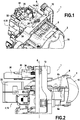
figure 1 est une vue partielle, en perspective de trois quart avant, d'un module d'éclairage selon l'invention ; - la
figure 2 est une vue de côté du module d'éclairage de lafigure 1 ; - la
figure 3 est une vue en perspective éclatée d'une embase servant de support de rotation au module d'éclairage de lafigure 1 , d'une pièce de support d'un ventilateur venant former avec l'embase un palier de guidage en rotation du module ; - la
figure 4 est une vue assemblée du support de ventilateur et du ventilateur qu'il supporte ; et - la
figure 5 est une vue en perspective, vue de trois quart arrière, du support de ventilateur de lafigure 3
- the
figure 1 is a partial view, in perspective of three quarters front, of a lighting module according to the invention; - the
figure 2 is a side view of the lighting module of thefigure 1 ; - the
figure 3 is an exploded perspective view of a base serving as a rotation support for the lighting module of thefigure 1 , a support part of a fan forming with the base a guide bearing in rotation of the module; - the
figure 4 is an assembled view of the fan support and the fan it supports; and - the
figure 5 is a perspective view, seen from three quarter back, of the fan support of thefigure 3
Dans ce qui va suivre, les termes « avant » et « arrière » se comprendront par rapport à la direction principale d'émission de rayons en sortie du module lumineux, le long de l'axe optique du module, et au sens d'émission de ces rayons de l'arrière vers l'avant. Et les références relatives à un positionnement « haut/bas » des composants et/ou des éléments structurels d'un composant seront comprises par rapport à un positionnement de fonctionnement du module dans le véhicule.In what follows, the terms "front" and "back" will be understood with respect to the main direction of ray emission at the output of the light module, along the optical axis of the module, and in the direction of transmission from these rays from the back to the front. And the references relating to a "up / down" positioning of the components and / or the structural elements of a component will be understood with respect to an operating position of the module in the vehicle.
Un dispositif d'éclairage et/ou de signalisation 1 configuré selon l'invention pour participer à une fonction d'éclairage directionnel comporte au moins un module lumineux 2 tel qu'il va être décrit à titre d'exemple ci-après. Ce au moins un module lumineux peut notamment être logé, seul ou au voisinage d'autres modules lumineux, dans un boîtier du dispositif fermé par une glace de fermeture.A lighting and / or signaling device 1 configured according to the invention to participate in a directional lighting function comprises at least one
Un module lumineux 2 comporte des dispositifs d'émission de rayons lumineux, des organes de refroidissement 4 et un carter 6 configuré pour supporter l'ensemble de ces éléments. Le module est rotatif en ce que le carter coopère avec des éléments d'entraînement 8 prévus pour mettre en rotation le carter et notamment les dispositifs d'émission autour d'un axe de rotation A-A, la rotation étant facilitée par au moins des éléments de guidage en rotation 10. Avantageusement, un palier de guidage 11 de ces éléments de guidage en rotation 10 est formé par la coopération d'une partie d'une embase 12 avec une pièce additionnelle 14 rapportée contre cette partie de l'embase.A
Le module lumineux 2 est monté pivotant autour de l'axe de rotation A-A par rapport à l'embase 12, par ailleurs fixée sur le boîtier, entre deux positions angulaires extrêmes, définies par l'encombrement du dispositif et la butée du module contre les parois de l'embase et qui permettent, selon la trajectoire du véhicule, une orientation droite / gauche du faisceau lumineux produit par le dispositif d'éclairage et/ou de signalisation.The
Les dispositifs d'émission de rayons lumineux comportent au moins une source lumineuse (non visible) et un système optique de mise en forme des rayons, comportant ici un réflecteur (non visible) et une lentille 16.The light-ray emitting devices comprise at least one light source (not visible) and an optical system for shaping the rays, here comprising a reflector (not visible) and a
Les organes de refroidissement 4 comportent notamment un échangeur thermique ou radiateur 18, qui présente une plaque de support 20, sur laquelle est disposé la au moins une source lumineuse, prolongée vers l'arrière du module par une succession d'ailettes de refroidissement 22.The cooling members 4 comprise in particular a heat exchanger or radiator 18, which has a
On comprend que la chaleur dégagée par la source lumineuse, et notamment par la plaque de circuits imprimés associée lorsque la source lumineuse est une diode électroluminescente, est évacuée du module par l'intermédiaire de la plaque de support et des ailettes de refroidissement.It is understood that the heat generated by the light source, and in particular by the associated printed circuit board when the light source is a light-emitting diode, is removed from the module via the support plate and the cooling fins.
Le carter 6 est configuré pour recouvrir au moins partiellement chacun des dispositifs d'émission et des organes de refroidissement du module, et pour assurer leur correcte mise en position les uns par rapport aux autres. Dans l'exemple illustré, le carter est formé de deux coques inférieure 6a et supérieure 6b disposées en regard et fixées, mais il sera compris que le nombre de sources lumineuses et de réflecteurs, ici un de chaque pour chaque coque, pourra varier de sorte qu'une seule coque est nécessaire pour former le carter.The
Chaque coque s'étend longitudinalement, c'est-à-dire dans la direction de l'axe optique du module, du radiateur 18 à la lentille 16.Each shell extends longitudinally, that is to say in the direction of the optical axis of the module, from the radiator 18 to the
La coque supérieure 6b comporte un pion 24 agencé en saillie de sa face supérieure pour coopérer avec l'embase 12 et former des éléments de guidage en rotation du module, tandis que la coque inférieure comporte un alésage creusé depuis sa face inférieure dont la section forme une empreinte complémentaire d'un élément mâle 26 des éléments d'entraînement 8 portés par l'embase.The
Le module est, dans le mode de réalisation, illustré entouré par l'embase 12 qui forme un cadre. L'embase est fixe, ici rendue solidaire du boîtier du dispositif d'éclairage et/ou de signalisation. Le cadre formant embase, notamment visible sur la
La barre inférieure 32 est dans le cas illustré solidaire des éléments d'entraînement 8 et de l'élément mâle 26 associé, étant entendu qu'un palier inférieur de guidage (ici non présent) en rotation pourrait être formé au niveau de cette barre inférieure.The
A l'opposé des éléments d'entraînement, c'est-à-dire de l'autre côté du module lorsque celui-ci est entouré du cadre formant l'embase, on prévoit un palier de guidage 11 en rotation formé en partie par la barre supérieure 30 de l'embase 12 et en partie par la pièce additionnelle 14 consistant en une pièce de support 34 d'un ventilateur 36.In contrast to the drive elements, that is to say on the other side of the module when it is surrounded by the frame forming the base, there is provided a rotational guide bearing 11 formed in part by the
Plus particulièrement, la barre supérieure comporte sensiblement en son centre une première encoche 37 qui forme une première partie du palier de guidage 11. Cette première encoche a un profil, dans un plan de coupe perpendiculaire à l'axe de rotation A-A, qui présente la forme d'un demi-cercle de dimension définie en adéquation avec le diamètre du pion amené à coopérer avec le palier de guidage 11 que participe à former cette première encoche.More particularly, the upper bar substantially comprises at its center a
Dans le mode de réalisation illustré, les éléments d'entraînement 8 jouent le rôle des éléments de guidage en rotation inférieurs. Ces éléments d'entraînement 8 et les éléments de guidage en rotation 10 réalisés sur le montant opposé, ici supérieur, du cadre sont agencés de façon coaxiale ou sensiblement coaxiale selon un axe A-A de rotation du module. On définit ainsi un palier supérieur et un palier inférieur, lesquels sont opposés et alignés selon l'axe A-A, ici vertical.In the illustrated embodiment, the driving elements 8 play the role of the lower rotational guiding elements. These drive elements 8 and the rotational guiding elements 10 made on the opposite amount, here higher, of the frame are arranged coaxially or substantially coaxially along an axis AA of rotation of the module. This defines an upper bearing and a lower bearing, which are opposite and aligned along the axis AA, here vertical.
Tel que cela a pu être précisé précédemment, le module présente sur son carter 6 des organes complémentaires respectivement des éléments d'entraînement et des paliers de guidage des éléments de guidage en rotation, et notamment par la présence d'un pion 24 dimensionné pour être logé dans le palier de guidage 11, éventuellement associé à des moyens d'arrêt en position pour empêcher le désengagement du pion hors du palier. On pourra prévoir un roulement pour faciliter la rotation du pion dans le palier et donc la rotation du module autour de l'axe de rotation A-A, sans que la présence de ce roulement soit indispensable au bon fonctionnement de l'invention. A l'extrémité opposé, au niveau de la barre inférieure de l'embase, et à titre d'exemple non limitatif, le carter pourra s'emboiter sur l'élément mâle 26 des éléments d'entraînement 8 par l'intermédiaire d'un orifice situé sur sa face inférieure et présentant une forme complémentaire, par exemple en section étoilée, de l'élément mâle.As has been previously stated, the module has on its
On va maintenant décrire plus en détails les éléments de guidage en rotation supérieurs, c'est-à-dire les éléments agencés à l'opposé des éléments d'entraînement par rapport au module, et en se référant notamment aux
La pièce de support 34 est configurée pour d'une part délimiter un alésage formant palier de guidage 11 en rotation lors de son accostage contre l'embase 12, et pour d'autre part recevoir au moins partiellement le ventilateur 36, de manière à le supporter dans une position de fonctionnement déterminée. On comprend que par « supporter » le ventilateur, on entend l'action de reprendre les efforts exercés sur le composant et de les transmettre à la structure du véhicule automobile. Dès lors, c'est le boîtier du projecteur et non le carter du module qui est impacté par le poids notamment du ventilateur, et les mouvements de rotation du module peuvent être plus rapides et plus fiables.The
On a pu illustrer sur les
La pièce de support 34 comporte un corps 38, prolongé à une première extrémité 40 par une pluralité de pions et de fûts et prolongé à une deuxième extrémité 42 opposée par des pattes de retenue 44 parallèles ou sensiblement parallèles entre elles.The
A la première extrémité 40, une paroi d'extrémité transversale 46 porte dans l'exemple illustré deux pions 48 et deux fûts 50 qui s'étendent à l'opposé du corps 38 de la pièce de support et qui sont configurés pour coopérer avec des éléments femelles correspondants agencés sur la barre supérieure 32 de l'embase. On comprend que les pions 48 permettent un indexage de positionnement de la pièce de support lors de son rapprochement contre la barre supérieure de l'embase et que les fûts permettent la fixation de la pièce de support sur l'embase par l'intermédiaire de vis ou pions de fixation 52 passant à travers ces fûts, formant ainsi des organes de fixation.At the
Les pions et les fûts sont agencés sur la paroi d'extrémité transversale 46 de part et d'autre d'une deuxième encoche 54 qui forme une deuxième partie du palier de guidage complémentaire de la première partie du palier de guidage formé par la première encoche. De façon miroir à ce qui a pu être décrit précédemment pour la première encoche 37 de la barre supérieure 32 de l'embase 12, la deuxième encoche 54 a un profil, dans un plan de coupe perpendiculaire à l'axe de rotation A-A, qui présente la forme d'un demi-cercle de dimension définie en adéquation avec le diamètre du pion amené à coopérer avec le palier de guidage 11 que participe à former cette deuxième encoche. On comprend de ce qui précède que les première 37 et deuxième 54 encoches présentent des profils symétriques dont l'assemblage permet la formation d'un palier de guidage en rotation de section circulaire. Sans sortir du contexte de l'invention, on pourrait prévoir que les encoches formant le palier présentent des profils différents et que l'une des encoches est plus profonde que l'autre encoche et consiste en un peu plus de la moitié du palier, dès lors que, lors de la fixation de la pièce de support contre l'embase, la face externe de la paroi d'extrémité transversale étant plaquée contre l'embase, le rapprochement des deux encoches forment un palier de guidage au pourtour circulaire.The pins and the drums are arranged on the
Par ailleurs, il convient de noter que la deuxième encoche 54 présente un épaulement 55 dans le prolongement du bord supérieur de l'encoche. On comprendra que cet épaulement peut permettre le logement de moyens d'arrêt en position d'un pion 24 à l'intérieur du palier de guidage 11. La première encoche 37 comportera avantageusement un épaulement symétrique (ici non visible sur la
Afin de faciliter la fixation des deux pièces formant le palier 11 des éléments de guidage en rotation 10, à savoir l'embase 12 et la pièce de support 34, on pourra prévoir que ces deux pièces sont réalisées dans un même matériau et par exemple un polymère thermoplastique du type polytéréphtalate de butylène (PBT), avantageusement chargé en fibres de verre.In order to facilitate the fixing of the two parts forming the bearing 11 of the rotating guide elements 10, namely the
La face interne de cette paroi d'extrémité transversale 46 forme la paroi de fond d'une cavité définie par le corps 38 creusé depuis l'extrémité opposée entre les pattes de retenue 44. Cette cavité permet d'une part de réduire le poids de la pièce, et elle permet l'insertion au moins partielle du ventilateur dans la pièce de support pour son positionnement correct avant fixation.The inner face of this
Les pattes de retenues 44 sont configurés pour coopérer par engagement avec des parties d'accroche du ventilateur 36. Des moyens de fixation additionnels, ici non représentés, peuvent être prévus pour figer la position du ventilateur entre les pattes de retenue. Plus particulièrement, deux premières pattes de retenue 44a disposées latéralement du même côté du corps 38 forment ensemble un élément de retenue du ventilateur, l'écartement de ces premières pattes de retenue étant tel que le ventilateur peut dans son épaisseur venir se loger entre ces deux premières pattes. Deux deuxièmes pattes de retenue 44b forment latéralement à l'opposé un élément de retenue similaire.The retaining
Les pattes de retenue 44 s'étendent horizontalement vers l'arrière de la pièce de support 34, de manière à ce que le ventilateur 36 se situe à l'aplomb des ailettes de refroidissement 22, selon la direction de l'axe de rotation A-A du module.The retaining
Le ventilateur 36 comporte un boîtier 56 à l'intérieur duquel sont agencées des pales rotatives 58. Le boîtier présente une forme de parallélépipède avec une face supérieure 36a et une face inférieure opposée 36b reliées l'une à l'autre par des parois latérales 36c. Les faces supérieure et inférieure, à base carrée, sont dégagées pour laisser passage au flux d'air perturbé par la rotation des pales. A chaque coin du boîtier, des alésages sont prévus traversants pour permettre la fixation du ventilateur.The
Dans la position assemblée du ventilateur 36 et de pièce de support 34, notamment visible sur la
Telle qu'elle vient d'être décrite, il peut être observé que dans la position assemblée du ventilateur et de la pièce de support, la surface active du ventilateur, c'est-à-dire la surface non recouverte par la pièce de support, est la plus importante possible.As just described, it can be observed that in the assembled position of the fan and the support part, the active surface of the fan, that is to say the surface not covered by the support piece , is the most important possible.
On peut observer sur la
Dans le module d'éclairage selon l'invention, on observe que les organes de refroidissement thermique suivent le mouvement de rotation du module puisque la plaque de support de la source lumineuse, porteuse des ailettes de refroidissement, est solidaire en rotation du carter 6. Et dans le même temps, au cours du déplacement pivotant du module, le ventilateur 36 reste quant à lui fixe puisque solidaire de l'embase 12 fixée au boîtier du dispositif d'éclairage et/ou de signalisation. Il est notable que le déplacement relatif du ventilateur par rapport aux ailettes de refroidissement participe à la perturbation du flux d'air amené à passer entre les ailettes, ce qui a pour effet d'améliorer l'efficacité de l'échange thermique avec le radiateur.In the lighting module according to the invention, it is observed that the thermal cooling members follow the rotational movement of the module since the support plate of the light source, carrying the cooling fins, is integral in rotation with the
La description qui précède vise à expliquer comment l'invention permet d'atteindre les objectifs qu'elle s'est fixés et notamment de proposer un dispositif d'éclairage et/ou de signalisation qui permette la réalisation d'un faisceau d'éclairage directionnel, avec au moins un module lumineux pour lequel on a modifié la structure d'une pièce pour lui donner une double fonction. Il en résulte un double avantage, dans un contexte de réduction du nombre de pièces à prévoir pour la réalisation des dispositifs d'éclairage et/ou de signalisation, consistant d'une part en le maintien du ventilateur par des éléments fixes par rapport au boîtier du dispositif et distincts du module tournant et d'autre part en la simplification du carter du module qui ne doit plus jouer le rôle de support du ventilateur. La forme de certaines pièces décrites ci-dessus, et par exemple celle de la pièce de support et/ou celle du ventilateur pourrait être modifiée dès lors que la pièce de support permet à la fois la réalisation d'un palier de guidage avec l'embase et le positionnement et la fixation d'un radiateur, à distance du corps du module rotatif. On pourra également envisager, sans sortir du contexte de l'invention, que l'embase ne présente pas une forme de cadre, mais par exemple la forme de deux barres supérieures et inférieures indépendantes l'une de l'autre et portant comme précédemment des éléments d'entraînement et des éléments de guidage en rotation.The foregoing description aims to explain how the invention makes it possible to achieve the objectives that it has set itself and in particular to propose a lighting and / or signaling device that allows the realization of a directional lighting beam. , with at least one light module for which the structure of a room has been modified to give it a dual function. This results in a double advantage, in a context of reducing the number of parts to provide for the production of lighting and / or signaling devices, consisting on the one hand in maintaining the fan by fixed elements relative to the housing of the device and separate from the rotating module and secondly in the simplification of the housing of the module which must no longer play the role of supporting the fan. The shape of some parts described above, and for example that of the support piece and / or that of the fan could be modified since the support piece allows both the realization of a guide bearing with the base and the positioning and fixing of a radiator, remote from the body of the rotary module. It may also be envisaged, without departing from the context of the invention, that the base does not have a frame shape, but for example the shape of two upper and lower bars independent of one another and bearing as previously driving elements and guide elements in rotation.
Claims (14)
- Directional lighting and/or signalling device (1) of a motor vehicle comprising at least:- one light module (2) that is rotationally mobile about an axis (A-A);- guiding elements (10) for rotationally guiding this light module (2) about the axis (A-A);- a base (12) supporting at least a part of the rotation guiding elements (10);- a fan (36);
characterized in that a bearing (11) of the rotation guiding elements (10) is formed partly by the base (12) and partly by a support piece (34) supporting the fan (36). - Directional lighting and/or signalling device according to Claim 1, characterized in that the guiding bearing (11) is formed by a portion of circular profile arranged on a wall of the base (12) and by a portion of circular profile arranged on a wall of the support piece (34) arranged facing the base.
- Directional lighting and/or signalling device according to Claim 2, characterized in that the guiding bearing (11) is formed by two portions of equivalent profiles, arranged mirror-fashion.
- Directional lighting and/or signalling device according to one of the preceding claims, characterized in that the support piece (34) is fixed to the base (12) by fixing members (52) arranged on either side of the guiding bearing (11) .
- Directional lighting and/or signalling device according to one of the preceding claims, characterized in that the base (12) and the support piece (34) are formed in one and the same material.
- Directional lighting and/or signalling device according to one of the preceding claims, characterized in that the support piece (34) has an open part for receiving an end of the fan (36).
- Directional lighting and/or signalling device according to the preceding claim, characterized in that the open part of the support piece (34) is formed opposite the part forming the guiding bearing (11).
- Directional lighting and/or signalling device according to one of the preceding claims, characterized in that the support piece (34) has at least fixing elements (44) for fixing the fan (36) .
- Directional lighting and/or signalling device according to the preceding claim, characterized in that the fixing elements (44) for fixing the fan (36) comprise at least one pair of retaining tabs (44) extending opposite the part of the support piece (34) forming the guiding bearing (11).
- Directional lighting and/or signalling device according to one of Claims 8 and 9, characterized in that the fixing elements (44) for fixing the fan (36) are arranged laterally in the support piece (34) while a positioning member (60) is arranged in a central portion relative to the support piece.
- Directional lighting and/or signalling device according to one of the preceding claims, characterized in that the light module (2) comprises at least light ray-emitting devices and cooling members (4).
- Directional lighting and/or signalling device according to the preceding claim, characterized in that the fan (36) is situated in line with at least a part of the cooling members (4), relative to the direction of the axis of rotation (A-A).
- Directional lighting and/or signalling device according to one of the preceding claims, characterized in that it comprises a casing defining, with a closing outer lens, a housing for the at least one rotationally mobile light module (2) .
- Directional lighting and/or signalling device according to the preceding claim, characterized in that the base (12) is fixed onto the casing.
Applications Claiming Priority (1)
| Application Number | Priority Date | Filing Date | Title |
|---|---|---|---|
| FR1654917A FR3051883B1 (en) | 2016-05-31 | 2016-05-31 | DEVICE FOR LIGHTING AND / OR SIGNALING A MOTOR VEHICLE |
Publications (2)
| Publication Number | Publication Date |
|---|---|
| EP3251895A1 EP3251895A1 (en) | 2017-12-06 |
| EP3251895B1 true EP3251895B1 (en) | 2019-06-26 |
Family
ID=56842847
Family Applications (1)
| Application Number | Title | Priority Date | Filing Date |
|---|---|---|---|
| EP17170689.8A Active EP3251895B1 (en) | 2016-05-31 | 2017-05-11 | Lighting and/or signalling device for a motor vehicle |
Country Status (5)
| Country | Link |
|---|---|
| US (1) | US10144340B2 (en) |
| EP (1) | EP3251895B1 (en) |
| JP (1) | JP6869811B2 (en) |
| CN (1) | CN107448859B (en) |
| FR (1) | FR3051883B1 (en) |
Families Citing this family (1)
| Publication number | Priority date | Publication date | Assignee | Title |
|---|---|---|---|---|
| DE102019106492A1 (en) * | 2019-03-14 | 2020-09-17 | HELLA GmbH & Co. KGaA | Holding device of a light module of a light unit, light module and light unit of a vehicle |
Family Cites Families (12)
| Publication number | Priority date | Publication date | Assignee | Title |
|---|---|---|---|---|
| US20070147060A1 (en) * | 2005-11-29 | 2007-06-28 | Wei-Jen Chen | Headlight driving device |
| FR2919547B1 (en) * | 2007-08-03 | 2010-01-08 | Valeo Vision | DEVICE FOR MOUNTING AN OPTICAL MODULE IN A PROJECTOR FOR A MOTOR VEHICLE |
| JP2010238604A (en) * | 2009-03-31 | 2010-10-21 | Koito Mfg Co Ltd | Light-emitting element modularization member and lighting fixture unit |
| FR2952870B1 (en) * | 2009-11-26 | 2015-06-19 | Valeo Vision | PIVOTING LIGHT MODULE AND CORRESPONDING SUPPORT FOR MOTOR VEHICLE |
| JP5518533B2 (en) * | 2010-03-12 | 2014-06-11 | 株式会社小糸製作所 | Vehicle headlamp and light emitting module for vehicle headlamp |
| FR2965039B1 (en) * | 2010-07-26 | 2016-04-15 | Valeo Vision | OPTICAL MODULE FOR A LIGHTING AND / OR SIGNALING DEVICE FOR A MOTOR VEHICLE |
| EP2598797B1 (en) * | 2010-07-26 | 2021-01-20 | Valeo Vision | Optical module of an illuminating and/or signalling device of a motor vehicle |
| CN103206622A (en) * | 2012-01-11 | 2013-07-17 | 欧司朗股份有限公司 | Light emitting device and improved lamp |
| JP6034608B2 (en) | 2012-07-18 | 2016-11-30 | 株式会社小糸製作所 | Vehicle headlamp |
| JP6345052B2 (en) * | 2013-12-20 | 2018-06-20 | 株式会社小糸製作所 | Vehicle headlamp |
| CN105371195A (en) * | 2014-08-26 | 2016-03-02 | 刘平 | Car lamp |
| CN105135320B (en) * | 2015-09-28 | 2017-10-20 | 台州探陆泽汽配有限公司 | A kind of headlight for vehicles |
-
2016
- 2016-05-31 FR FR1654917A patent/FR3051883B1/en active Active
-
2017
- 2017-05-11 EP EP17170689.8A patent/EP3251895B1/en active Active
- 2017-05-24 CN CN201710373369.0A patent/CN107448859B/en active Active
- 2017-05-30 JP JP2017106623A patent/JP6869811B2/en active Active
- 2017-05-31 US US15/609,817 patent/US10144340B2/en active Active
Non-Patent Citations (1)
| Title |
|---|
| None * |
Also Published As
| Publication number | Publication date |
|---|---|
| JP6869811B2 (en) | 2021-05-12 |
| US10144340B2 (en) | 2018-12-04 |
| CN107448859A (en) | 2017-12-08 |
| FR3051883A1 (en) | 2017-12-01 |
| EP3251895A1 (en) | 2017-12-06 |
| US20170341564A1 (en) | 2017-11-30 |
| CN107448859B (en) | 2022-03-29 |
| JP2018037399A (en) | 2018-03-08 |
| FR3051883B1 (en) | 2018-06-15 |
Similar Documents
| Publication | Publication Date | Title |
|---|---|---|
| CA2810385C (en) | Optical module of an illuminating and/or signalling device of a motor vehicle | |
| EP1686310B1 (en) | Vertically oriented vehicle headlamp | |
| CA2810700C (en) | Optical module of an illuminating and/or signalling device of a motor vehicle | |
| EP2598796B1 (en) | Optical module of an illuminating and/or signalling device of a motor vehicle | |
| EP3245443B1 (en) | Vehicle lighting device wherein a light guide supports another light guide | |
| EP1739346B1 (en) | Fog lamp with projection lens | |
| FR3032778A1 (en) | VEHICLE FIRE | |
| EP4065882B1 (en) | Light module of a motor vehicle equipped with an optical element | |
| EP2966343B1 (en) | Lighting module for a motor vehicle headlight with positioning means between heat sink and reflector/circuit board | |
| FR3025865A1 (en) | LIGHTING DEVICE OF A VEHICLE USING A MULTISOURCE OPTICAL LENS | |
| EP1790906B1 (en) | Lighting or signalling device for automotive vehicle | |
| EP3254019A1 (en) | Vehicle light module compatible with driving on the left and driving on the right | |
| EP3251895B1 (en) | Lighting and/or signalling device for a motor vehicle | |
| FR2964723A1 (en) | Optical module for lighting and signaling device such as headlight type lighting device, of motor vehicle, has reflectors that are formed on part equipped with cooling opening for circulation of cooling air | |
| FR3051412A1 (en) | LIGHTING AND / OR SIGNALING DEVICE FOR A MOTOR VEHICLE FOR IMPLANTING IN A BODY COMPONENT | |
| FR3064721B1 (en) | LUMINOUS DEVICE WITH RADIATOR CROSSING THE HOUSING | |
| EP3221185B1 (en) | Lighting unit for a vehicle and corresponding vehicle | |
| WO2022129617A1 (en) | Light-emitting device for a motor vehicle | |
| FR2964724A1 (en) | Optical module for lighting and signaling device e.g. headlight type light projector, of motor vehicle, has folding element fixed in module in motionless manner with respect to light source, where folding element is made by metal piece | |
| FR2911664A1 (en) | Signaling or lighting module for e.g. car, has flux-recovering mirror including ellipsoid portion whose parameters constituting reflecting paves are adjusted to compare predetermined photometric characteristics with hearth of mirror |
Legal Events
| Date | Code | Title | Description |
|---|---|---|---|
| PUAI | Public reference made under article 153(3) epc to a published international application that has entered the european phase |
Free format text: ORIGINAL CODE: 0009012 |
|
| STAA | Information on the status of an ep patent application or granted ep patent |
Free format text: STATUS: THE APPLICATION HAS BEEN PUBLISHED |
|
| AK | Designated contracting states |
Kind code of ref document: A1 Designated state(s): AL AT BE BG CH CY CZ DE DK EE ES FI FR GB GR HR HU IE IS IT LI LT LU LV MC MK MT NL NO PL PT RO RS SE SI SK SM TR |
|
| AX | Request for extension of the european patent |
Extension state: BA ME |
|
| STAA | Information on the status of an ep patent application or granted ep patent |
Free format text: STATUS: REQUEST FOR EXAMINATION WAS MADE |
|
| 17P | Request for examination filed |
Effective date: 20180601 |
|
| RBV | Designated contracting states (corrected) |
Designated state(s): AL AT BE BG CH CY CZ DE DK EE ES FI FR GB GR HR HU IE IS IT LI LT LU LV MC MK MT NL NO PL PT RO RS SE SI SK SM TR |
|
| REG | Reference to a national code |
Ref country code: DE Ref legal event code: R079 Ref document number: 602017004776 Country of ref document: DE Free format text: PREVIOUS MAIN CLASS: B60Q0001060000 Ipc: B60Q0001076000 |
|
| RIC1 | Information provided on ipc code assigned before grant |
Ipc: F21S 45/43 20180101ALI20181214BHEP Ipc: B60Q 1/076 20060101AFI20181214BHEP Ipc: F21S 45/49 20180101ALI20181214BHEP |
|
| GRAP | Despatch of communication of intention to grant a patent |
Free format text: ORIGINAL CODE: EPIDOSNIGR1 |
|
| STAA | Information on the status of an ep patent application or granted ep patent |
Free format text: STATUS: GRANT OF PATENT IS INTENDED |
|
| INTG | Intention to grant announced |
Effective date: 20190129 |
|
| GRAS | Grant fee paid |
Free format text: ORIGINAL CODE: EPIDOSNIGR3 |
|
| GRAA | (expected) grant |
Free format text: ORIGINAL CODE: 0009210 |
|
| STAA | Information on the status of an ep patent application or granted ep patent |
Free format text: STATUS: THE PATENT HAS BEEN GRANTED |
|
| AK | Designated contracting states |
Kind code of ref document: B1 Designated state(s): AL AT BE BG CH CY CZ DE DK EE ES FI FR GB GR HR HU IE IS IT LI LT LU LV MC MK MT NL NO PL PT RO RS SE SI SK SM TR |
|
| REG | Reference to a national code |
Ref country code: GB Ref legal event code: FG4D Free format text: NOT ENGLISH |
|
| REG | Reference to a national code |
Ref country code: CH Ref legal event code: EP |
|
| REG | Reference to a national code |
Ref country code: AT Ref legal event code: REF Ref document number: 1147905 Country of ref document: AT Kind code of ref document: T Effective date: 20190715 |
|
| REG | Reference to a national code |
Ref country code: DE Ref legal event code: R096 Ref document number: 602017004776 Country of ref document: DE |
|
| REG | Reference to a national code |
Ref country code: IE Ref legal event code: FG4D Free format text: LANGUAGE OF EP DOCUMENT: FRENCH |
|
| REG | Reference to a national code |
Ref country code: NL Ref legal event code: FP |
|
| PG25 | Lapsed in a contracting state [announced via postgrant information from national office to epo] |
Ref country code: SE Free format text: LAPSE BECAUSE OF FAILURE TO SUBMIT A TRANSLATION OF THE DESCRIPTION OR TO PAY THE FEE WITHIN THE PRESCRIBED TIME-LIMIT Effective date: 20190626 Ref country code: LT Free format text: LAPSE BECAUSE OF FAILURE TO SUBMIT A TRANSLATION OF THE DESCRIPTION OR TO PAY THE FEE WITHIN THE PRESCRIBED TIME-LIMIT Effective date: 20190626 Ref country code: NO Free format text: LAPSE BECAUSE OF FAILURE TO SUBMIT A TRANSLATION OF THE DESCRIPTION OR TO PAY THE FEE WITHIN THE PRESCRIBED TIME-LIMIT Effective date: 20190926 Ref country code: AL Free format text: LAPSE BECAUSE OF FAILURE TO SUBMIT A TRANSLATION OF THE DESCRIPTION OR TO PAY THE FEE WITHIN THE PRESCRIBED TIME-LIMIT Effective date: 20190626 Ref country code: HR Free format text: LAPSE BECAUSE OF FAILURE TO SUBMIT A TRANSLATION OF THE DESCRIPTION OR TO PAY THE FEE WITHIN THE PRESCRIBED TIME-LIMIT Effective date: 20190626 Ref country code: FI Free format text: LAPSE BECAUSE OF FAILURE TO SUBMIT A TRANSLATION OF THE DESCRIPTION OR TO PAY THE FEE WITHIN THE PRESCRIBED TIME-LIMIT Effective date: 20190626 |
|
| REG | Reference to a national code |
Ref country code: LT Ref legal event code: MG4D |
|
| PG25 | Lapsed in a contracting state [announced via postgrant information from national office to epo] |
Ref country code: GR Free format text: LAPSE BECAUSE OF FAILURE TO SUBMIT A TRANSLATION OF THE DESCRIPTION OR TO PAY THE FEE WITHIN THE PRESCRIBED TIME-LIMIT Effective date: 20190927 Ref country code: BG Free format text: LAPSE BECAUSE OF FAILURE TO SUBMIT A TRANSLATION OF THE DESCRIPTION OR TO PAY THE FEE WITHIN THE PRESCRIBED TIME-LIMIT Effective date: 20190926 Ref country code: RS Free format text: LAPSE BECAUSE OF FAILURE TO SUBMIT A TRANSLATION OF THE DESCRIPTION OR TO PAY THE FEE WITHIN THE PRESCRIBED TIME-LIMIT Effective date: 20190626 Ref country code: LV Free format text: LAPSE BECAUSE OF FAILURE TO SUBMIT A TRANSLATION OF THE DESCRIPTION OR TO PAY THE FEE WITHIN THE PRESCRIBED TIME-LIMIT Effective date: 20190626 |
|
| REG | Reference to a national code |
Ref country code: AT Ref legal event code: MK05 Ref document number: 1147905 Country of ref document: AT Kind code of ref document: T Effective date: 20190626 |
|
| PG25 | Lapsed in a contracting state [announced via postgrant information from national office to epo] |
Ref country code: AT Free format text: LAPSE BECAUSE OF FAILURE TO SUBMIT A TRANSLATION OF THE DESCRIPTION OR TO PAY THE FEE WITHIN THE PRESCRIBED TIME-LIMIT Effective date: 20190626 Ref country code: EE Free format text: LAPSE BECAUSE OF FAILURE TO SUBMIT A TRANSLATION OF THE DESCRIPTION OR TO PAY THE FEE WITHIN THE PRESCRIBED TIME-LIMIT Effective date: 20190626 Ref country code: SK Free format text: LAPSE BECAUSE OF FAILURE TO SUBMIT A TRANSLATION OF THE DESCRIPTION OR TO PAY THE FEE WITHIN THE PRESCRIBED TIME-LIMIT Effective date: 20190626 Ref country code: PT Free format text: LAPSE BECAUSE OF FAILURE TO SUBMIT A TRANSLATION OF THE DESCRIPTION OR TO PAY THE FEE WITHIN THE PRESCRIBED TIME-LIMIT Effective date: 20191028 Ref country code: RO Free format text: LAPSE BECAUSE OF FAILURE TO SUBMIT A TRANSLATION OF THE DESCRIPTION OR TO PAY THE FEE WITHIN THE PRESCRIBED TIME-LIMIT Effective date: 20190626 Ref country code: CZ Free format text: LAPSE BECAUSE OF FAILURE TO SUBMIT A TRANSLATION OF THE DESCRIPTION OR TO PAY THE FEE WITHIN THE PRESCRIBED TIME-LIMIT Effective date: 20190626 |
|
| PG25 | Lapsed in a contracting state [announced via postgrant information from national office to epo] |
Ref country code: IS Free format text: LAPSE BECAUSE OF FAILURE TO SUBMIT A TRANSLATION OF THE DESCRIPTION OR TO PAY THE FEE WITHIN THE PRESCRIBED TIME-LIMIT Effective date: 20191026 Ref country code: ES Free format text: LAPSE BECAUSE OF FAILURE TO SUBMIT A TRANSLATION OF THE DESCRIPTION OR TO PAY THE FEE WITHIN THE PRESCRIBED TIME-LIMIT Effective date: 20190626 Ref country code: SM Free format text: LAPSE BECAUSE OF FAILURE TO SUBMIT A TRANSLATION OF THE DESCRIPTION OR TO PAY THE FEE WITHIN THE PRESCRIBED TIME-LIMIT Effective date: 20190626 Ref country code: IT Free format text: LAPSE BECAUSE OF FAILURE TO SUBMIT A TRANSLATION OF THE DESCRIPTION OR TO PAY THE FEE WITHIN THE PRESCRIBED TIME-LIMIT Effective date: 20190626 |
|
| PG25 | Lapsed in a contracting state [announced via postgrant information from national office to epo] |
Ref country code: TR Free format text: LAPSE BECAUSE OF FAILURE TO SUBMIT A TRANSLATION OF THE DESCRIPTION OR TO PAY THE FEE WITHIN THE PRESCRIBED TIME-LIMIT Effective date: 20190626 |
|
| PG25 | Lapsed in a contracting state [announced via postgrant information from national office to epo] |
Ref country code: PL Free format text: LAPSE BECAUSE OF FAILURE TO SUBMIT A TRANSLATION OF THE DESCRIPTION OR TO PAY THE FEE WITHIN THE PRESCRIBED TIME-LIMIT Effective date: 20190626 Ref country code: DK Free format text: LAPSE BECAUSE OF FAILURE TO SUBMIT A TRANSLATION OF THE DESCRIPTION OR TO PAY THE FEE WITHIN THE PRESCRIBED TIME-LIMIT Effective date: 20190626 |
|
| PG25 | Lapsed in a contracting state [announced via postgrant information from national office to epo] |
Ref country code: IS Free format text: LAPSE BECAUSE OF FAILURE TO SUBMIT A TRANSLATION OF THE DESCRIPTION OR TO PAY THE FEE WITHIN THE PRESCRIBED TIME-LIMIT Effective date: 20200320 |
|
| REG | Reference to a national code |
Ref country code: DE Ref legal event code: R097 Ref document number: 602017004776 Country of ref document: DE |
|
| PLBE | No opposition filed within time limit |
Free format text: ORIGINAL CODE: 0009261 |
|
| STAA | Information on the status of an ep patent application or granted ep patent |
Free format text: STATUS: NO OPPOSITION FILED WITHIN TIME LIMIT |
|
| PG2D | Information on lapse in contracting state deleted |
Ref country code: IS |
|
| 26N | No opposition filed |
Effective date: 20200603 |
|
| PG25 | Lapsed in a contracting state [announced via postgrant information from national office to epo] |
Ref country code: SI Free format text: LAPSE BECAUSE OF FAILURE TO SUBMIT A TRANSLATION OF THE DESCRIPTION OR TO PAY THE FEE WITHIN THE PRESCRIBED TIME-LIMIT Effective date: 20190626 |
|
| PG25 | Lapsed in a contracting state [announced via postgrant information from national office to epo] |
Ref country code: LI Free format text: LAPSE BECAUSE OF NON-PAYMENT OF DUE FEES Effective date: 20200531 Ref country code: MC Free format text: LAPSE BECAUSE OF FAILURE TO SUBMIT A TRANSLATION OF THE DESCRIPTION OR TO PAY THE FEE WITHIN THE PRESCRIBED TIME-LIMIT Effective date: 20190626 Ref country code: CH Free format text: LAPSE BECAUSE OF NON-PAYMENT OF DUE FEES Effective date: 20200531 |
|
| REG | Reference to a national code |
Ref country code: BE Ref legal event code: MM Effective date: 20200531 |
|
| PG25 | Lapsed in a contracting state [announced via postgrant information from national office to epo] |
Ref country code: LU Free format text: LAPSE BECAUSE OF NON-PAYMENT OF DUE FEES Effective date: 20200511 |
|
| PG25 | Lapsed in a contracting state [announced via postgrant information from national office to epo] |
Ref country code: IE Free format text: LAPSE BECAUSE OF NON-PAYMENT OF DUE FEES Effective date: 20200511 |
|
| PG25 | Lapsed in a contracting state [announced via postgrant information from national office to epo] |
Ref country code: BE Free format text: LAPSE BECAUSE OF NON-PAYMENT OF DUE FEES Effective date: 20200531 |
|
| GBPC | Gb: european patent ceased through non-payment of renewal fee |
Effective date: 20210511 |
|
| PG25 | Lapsed in a contracting state [announced via postgrant information from national office to epo] |
Ref country code: GB Free format text: LAPSE BECAUSE OF NON-PAYMENT OF DUE FEES Effective date: 20210511 |
|
| PG25 | Lapsed in a contracting state [announced via postgrant information from national office to epo] |
Ref country code: MT Free format text: LAPSE BECAUSE OF FAILURE TO SUBMIT A TRANSLATION OF THE DESCRIPTION OR TO PAY THE FEE WITHIN THE PRESCRIBED TIME-LIMIT Effective date: 20190626 Ref country code: CY Free format text: LAPSE BECAUSE OF FAILURE TO SUBMIT A TRANSLATION OF THE DESCRIPTION OR TO PAY THE FEE WITHIN THE PRESCRIBED TIME-LIMIT Effective date: 20190626 |
|
| PG25 | Lapsed in a contracting state [announced via postgrant information from national office to epo] |
Ref country code: MK Free format text: LAPSE BECAUSE OF FAILURE TO SUBMIT A TRANSLATION OF THE DESCRIPTION OR TO PAY THE FEE WITHIN THE PRESCRIBED TIME-LIMIT Effective date: 20190626 |
|
| PGFP | Annual fee paid to national office [announced via postgrant information from national office to epo] |
Ref country code: NL Payment date: 20230427 Year of fee payment: 7 |
|
| P01 | Opt-out of the competence of the unified patent court (upc) registered |
Effective date: 20230528 |
|
| PGFP | Annual fee paid to national office [announced via postgrant information from national office to epo] |
Ref country code: FR Payment date: 20230523 Year of fee payment: 7 Ref country code: DE Payment date: 20230510 Year of fee payment: 7 |