EP3248047B1 - Flexibler wärmeleiter für eine elektronische vorrichtung - Google Patents
Flexibler wärmeleiter für eine elektronische vorrichtung Download PDFInfo
- Publication number
- EP3248047B1 EP3248047B1 EP16705319.8A EP16705319A EP3248047B1 EP 3248047 B1 EP3248047 B1 EP 3248047B1 EP 16705319 A EP16705319 A EP 16705319A EP 3248047 B1 EP3248047 B1 EP 3248047B1
- Authority
- EP
- European Patent Office
- Prior art keywords
- head
- flexible
- assembly
- layers
- flexible thermal
- Prior art date
- Legal status (The legal status is an assumption and is not a legal conclusion. Google has not performed a legal analysis and makes no representation as to the accuracy of the status listed.)
- Active
Links
Images


Classifications
-
- G—PHYSICS
- G02—OPTICS
- G02B—OPTICAL ELEMENTS, SYSTEMS OR APPARATUS
- G02B27/00—Optical systems or apparatus not provided for by any of the groups G02B1/00 - G02B26/00, G02B30/00
- G02B27/01—Head-up displays
- G02B27/017—Head mounted
- G02B27/0176—Head mounted characterised by mechanical features
-
- H—ELECTRICITY
- H05—ELECTRIC TECHNIQUES NOT OTHERWISE PROVIDED FOR
- H05K—PRINTED CIRCUITS; CASINGS OR CONSTRUCTIONAL DETAILS OF ELECTRIC APPARATUS; MANUFACTURE OF ASSEMBLAGES OF ELECTRICAL COMPONENTS
- H05K7/00—Constructional details common to different types of electric apparatus
- H05K7/20—Modifications to facilitate cooling, ventilating, or heating
- H05K7/20954—Modifications to facilitate cooling, ventilating, or heating for display panels
- H05K7/20963—Heat transfer by conduction from internal heat source to heat radiating structure
-
- F—MECHANICAL ENGINEERING; LIGHTING; HEATING; WEAPONS; BLASTING
- F28—HEAT EXCHANGE IN GENERAL
- F28D—HEAT-EXCHANGE APPARATUS, NOT PROVIDED FOR IN ANOTHER SUBCLASS, IN WHICH THE HEAT-EXCHANGE MEDIA DO NOT COME INTO DIRECT CONTACT
- F28D15/00—Heat-exchange apparatus with the intermediate heat-transfer medium in closed tubes passing into or through the conduit walls ; Heat-exchange apparatus employing intermediate heat-transfer medium or bodies
- F28D15/02—Heat-exchange apparatus with the intermediate heat-transfer medium in closed tubes passing into or through the conduit walls ; Heat-exchange apparatus employing intermediate heat-transfer medium or bodies in which the medium condenses and evaporates, e.g. heat pipes
- F28D15/0241—Heat-exchange apparatus with the intermediate heat-transfer medium in closed tubes passing into or through the conduit walls ; Heat-exchange apparatus employing intermediate heat-transfer medium or bodies in which the medium condenses and evaporates, e.g. heat pipes the tubes being flexible
-
- F—MECHANICAL ENGINEERING; LIGHTING; HEATING; WEAPONS; BLASTING
- F28—HEAT EXCHANGE IN GENERAL
- F28F—DETAILS OF HEAT-EXCHANGE AND HEAT-TRANSFER APPARATUS, OF GENERAL APPLICATION
- F28F21/00—Constructions of heat-exchange apparatus characterised by the selection of particular materials
-
- F—MECHANICAL ENGINEERING; LIGHTING; HEATING; WEAPONS; BLASTING
- F28—HEAT EXCHANGE IN GENERAL
- F28F—DETAILS OF HEAT-EXCHANGE AND HEAT-TRANSFER APPARATUS, OF GENERAL APPLICATION
- F28F21/00—Constructions of heat-exchange apparatus characterised by the selection of particular materials
- F28F21/02—Constructions of heat-exchange apparatus characterised by the selection of particular materials of carbon, e.g. graphite
-
- F—MECHANICAL ENGINEERING; LIGHTING; HEATING; WEAPONS; BLASTING
- F28—HEAT EXCHANGE IN GENERAL
- F28F—DETAILS OF HEAT-EXCHANGE AND HEAT-TRANSFER APPARATUS, OF GENERAL APPLICATION
- F28F21/00—Constructions of heat-exchange apparatus characterised by the selection of particular materials
- F28F21/08—Constructions of heat-exchange apparatus characterised by the selection of particular materials of metal
-
- F—MECHANICAL ENGINEERING; LIGHTING; HEATING; WEAPONS; BLASTING
- F28—HEAT EXCHANGE IN GENERAL
- F28F—DETAILS OF HEAT-EXCHANGE AND HEAT-TRANSFER APPARATUS, OF GENERAL APPLICATION
- F28F3/00—Plate-like or laminated elements; Assemblies of plate-like or laminated elements
- F28F3/02—Elements or assemblies thereof with means for increasing heat-transfer area, e.g. with fins, with recesses, with corrugations
-
- F—MECHANICAL ENGINEERING; LIGHTING; HEATING; WEAPONS; BLASTING
- F28—HEAT EXCHANGE IN GENERAL
- F28F—DETAILS OF HEAT-EXCHANGE AND HEAT-TRANSFER APPARATUS, OF GENERAL APPLICATION
- F28F3/00—Plate-like or laminated elements; Assemblies of plate-like or laminated elements
- F28F3/08—Elements constructed for building-up into stacks, e.g. capable of being taken apart for cleaning
-
- G—PHYSICS
- G06—COMPUTING OR CALCULATING; COUNTING
- G06F—ELECTRIC DIGITAL DATA PROCESSING
- G06F1/00—Details not covered by groups G06F3/00 - G06F13/00 and G06F21/00
- G06F1/16—Constructional details or arrangements
- G06F1/1613—Constructional details or arrangements for portable computers
- G06F1/163—Wearable computers, e.g. on a belt
-
- G—PHYSICS
- G06—COMPUTING OR CALCULATING; COUNTING
- G06F—ELECTRIC DIGITAL DATA PROCESSING
- G06F1/00—Details not covered by groups G06F3/00 - G06F13/00 and G06F21/00
- G06F1/16—Constructional details or arrangements
- G06F1/1613—Constructional details or arrangements for portable computers
- G06F1/1633—Constructional details or arrangements of portable computers not specific to the type of enclosures covered by groups G06F1/1615 - G06F1/1626
- G06F1/1675—Miscellaneous details related to the relative movement between the different enclosures or enclosure parts
- G06F1/1681—Details related solely to hinges
-
- G—PHYSICS
- G06—COMPUTING OR CALCULATING; COUNTING
- G06F—ELECTRIC DIGITAL DATA PROCESSING
- G06F1/00—Details not covered by groups G06F3/00 - G06F13/00 and G06F21/00
- G06F1/16—Constructional details or arrangements
- G06F1/20—Cooling means
- G06F1/203—Cooling means for portable computers, e.g. for laptops
-
- G—PHYSICS
- G06—COMPUTING OR CALCULATING; COUNTING
- G06F—ELECTRIC DIGITAL DATA PROCESSING
- G06F3/00—Input arrangements for transferring data to be processed into a form capable of being handled by the computer; Output arrangements for transferring data from processing unit to output unit, e.g. interface arrangements
- G06F3/01—Input arrangements or combined input and output arrangements for interaction between user and computer
- G06F3/011—Arrangements for interaction with the human body, e.g. for user immersion in virtual reality
-
- H—ELECTRICITY
- H05—ELECTRIC TECHNIQUES NOT OTHERWISE PROVIDED FOR
- H05K—PRINTED CIRCUITS; CASINGS OR CONSTRUCTIONAL DETAILS OF ELECTRIC APPARATUS; MANUFACTURE OF ASSEMBLAGES OF ELECTRICAL COMPONENTS
- H05K1/00—Printed circuits
- H05K1/02—Details
- H05K1/0201—Thermal arrangements, e.g. for cooling, heating or preventing overheating
-
- H—ELECTRICITY
- H05—ELECTRIC TECHNIQUES NOT OTHERWISE PROVIDED FOR
- H05K—PRINTED CIRCUITS; CASINGS OR CONSTRUCTIONAL DETAILS OF ELECTRIC APPARATUS; MANUFACTURE OF ASSEMBLAGES OF ELECTRICAL COMPONENTS
- H05K5/00—Casings, cabinets or drawers for electric apparatus
- H05K5/02—Details
- H05K5/0217—Mechanical details of casings
- H05K5/0226—Hinges
-
- H—ELECTRICITY
- H05—ELECTRIC TECHNIQUES NOT OTHERWISE PROVIDED FOR
- H05K—PRINTED CIRCUITS; CASINGS OR CONSTRUCTIONAL DETAILS OF ELECTRIC APPARATUS; MANUFACTURE OF ASSEMBLAGES OF ELECTRICAL COMPONENTS
- H05K7/00—Constructional details common to different types of electric apparatus
- H05K7/20—Modifications to facilitate cooling, ventilating, or heating
- H05K7/20009—Modifications to facilitate cooling, ventilating, or heating using a gaseous coolant in electronic enclosures
- H05K7/20127—Natural convection
-
- H—ELECTRICITY
- H05—ELECTRIC TECHNIQUES NOT OTHERWISE PROVIDED FOR
- H05K—PRINTED CIRCUITS; CASINGS OR CONSTRUCTIONAL DETAILS OF ELECTRIC APPARATUS; MANUFACTURE OF ASSEMBLAGES OF ELECTRICAL COMPONENTS
- H05K7/00—Constructional details common to different types of electric apparatus
- H05K7/20—Modifications to facilitate cooling, ventilating, or heating
- H05K7/2039—Modifications to facilitate cooling, ventilating, or heating characterised by the heat transfer by conduction from the heat generating element to a dissipating body
- H05K7/20409—Outer radiating structures on heat dissipating housings, e.g. fins integrated with the housing
-
- H—ELECTRICITY
- H05—ELECTRIC TECHNIQUES NOT OTHERWISE PROVIDED FOR
- H05K—PRINTED CIRCUITS; CASINGS OR CONSTRUCTIONAL DETAILS OF ELECTRIC APPARATUS; MANUFACTURE OF ASSEMBLAGES OF ELECTRICAL COMPONENTS
- H05K7/00—Constructional details common to different types of electric apparatus
- H05K7/20—Modifications to facilitate cooling, ventilating, or heating
- H05K7/2039—Modifications to facilitate cooling, ventilating, or heating characterised by the heat transfer by conduction from the heat generating element to a dissipating body
- H05K7/20436—Inner thermal coupling elements in heat dissipating housings, e.g. protrusions or depressions integrally formed in the housing
- H05K7/20445—Inner thermal coupling elements in heat dissipating housings, e.g. protrusions or depressions integrally formed in the housing the coupling element being an additional piece, e.g. thermal standoff
- H05K7/20454—Inner thermal coupling elements in heat dissipating housings, e.g. protrusions or depressions integrally formed in the housing the coupling element being an additional piece, e.g. thermal standoff with a conformable or flexible structure compensating for irregularities, e.g. cushion bags, thermal paste
-
- H10W40/255—
-
- H10W40/257—
-
- H10W40/258—
-
- F—MECHANICAL ENGINEERING; LIGHTING; HEATING; WEAPONS; BLASTING
- F28—HEAT EXCHANGE IN GENERAL
- F28F—DETAILS OF HEAT-EXCHANGE AND HEAT-TRANSFER APPARATUS, OF GENERAL APPLICATION
- F28F21/00—Constructions of heat-exchange apparatus characterised by the selection of particular materials
- F28F21/08—Constructions of heat-exchange apparatus characterised by the selection of particular materials of metal
- F28F21/081—Heat exchange elements made from metals or metal alloys
- F28F21/085—Heat exchange elements made from metals or metal alloys from copper or copper alloys
-
- F—MECHANICAL ENGINEERING; LIGHTING; HEATING; WEAPONS; BLASTING
- F28—HEAT EXCHANGE IN GENERAL
- F28F—DETAILS OF HEAT-EXCHANGE AND HEAT-TRANSFER APPARATUS, OF GENERAL APPLICATION
- F28F2255/00—Heat exchanger elements made of materials having special features or resulting from particular manufacturing processes
- F28F2255/02—Flexible elements
-
- G—PHYSICS
- G02—OPTICS
- G02B—OPTICAL ELEMENTS, SYSTEMS OR APPARATUS
- G02B27/00—Optical systems or apparatus not provided for by any of the groups G02B1/00 - G02B26/00, G02B30/00
- G02B27/01—Head-up displays
- G02B27/017—Head mounted
- G02B2027/0178—Eyeglass type
-
- H10W40/242—
Definitions
- Cooling capacity for passively cooled electronic devices is limited by the area of surfaces available for heat transfer via radiation and natural convection, and the orientation of those surfaces.
- heat exchange surface area In products that have a housing to isolate electronic components from the environment, there is an inherent limit on heat exchange surface area, which imposes significant design challenges. Heat dissipation is even more of a challenge for compact, low-mass and low-volume consumer product designs.
- EP2327542 teaches a laminate having a graphite foil layer, and another graphite foil layer sectionally arranged at a distance to the former graphite foil layer.
- An intermediate layer is arranged between the two graphite foil layers.
- the two graphite foil layers and the intermediate layer are laminated together.
- a flexible thermal conduit that runs from a first housing portion of an electronic device to a second housing portion of the electronic device, to convey heat generated by an electronic component in the first housing portion to a heat dissipation structure in the second housing portion.
- the flexible thermal conduit is particularly useful where the first housing portion (which includes the electronic component) has insufficient space for the heat dissipation structure.
- the flexible thermal conduit is particularly useful in products where the second housing portion is flexibly coupled to the first housing portion, for example, by a hinge or other type of joint.
- the flexible thermal conduit includes a plurality of layers of flexible thermal conduit material, where the layers are not affixed to each other in the region where the second housing portion is coupled to the first housing portion, thereby enabling the layers to flex independently of each other in that region.
- the layers can include, for example, one or more layers of flexible graphite and/or one or more layers of thin metal.
- references to "an embodiment”, “one embodiment” or the like, mean that the particular feature, function, structure or characteristic being described is included in at least one embodiment of the technique introduced here. Occurrences of such phrases in this specification do not necessarily all refer to the same embodiment. On the other hand, the embodiments referred to also are not necessarily mutually exclusive.
- the flexible thermal conduit introduced here is particularly useful in products that have multiple housing portions that are movably coupled to each other, where it is impractical (e.g. to space limitations) to locate the heat dissipation structure in the same housing portion as the heat generating components.
- a head mounted display (HMD) device where the first housing portion is a space- and weight-constrained visor assembly that contains display elements and other heat-generating electronics, and the second housing portion is part of a head fitting assembly that enables the device to be worn on a user's head, where the head fitting assembly is flexibly connected to the visor assembly (e.g., by a hinge).
- HMD head mounted display
- the flexible thermal conduit introduced here can also be incorporated advantageously into many other types of products, such as in laptop computers or flip-top type cell phones (e.g., to transfer heat from the display portion to the main body of the device via a hinge).
- An HMD device can be used for augmented reality (AR) and/or virtual reality applications, for example.
- AR HMD devices (“AR-HMD” devices) include transparent display elements that enable a user to see concurrently both the real world around them and AR content displayed by the device.
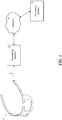
- Figure 1 schematically shows an example of an environment in which an AR-HMD device such as described herein can be used.
- the AR-HMD device 1 is configured to communicate data to and from an external processing device 2 through a connection 3, which can be a wired connection, a wireless connection, or a combination thereof. In other use cases, however, the AR-HMD device 1 may operate as a standalone device.
- the connection 3 can be configured to carry any kind of data, such as image data (e.g., still images and/or full-motion video, including 2D and 3D images), audio, multimedia, voice, and/or any other type(s) of data.
- the processing system 2 may be, for example, a game console, personal computer, tablet computer, smartphone, or other type of processing device.
- the connection 3 can be, for example, a universal serial bus (USB) connection, Wi-Fi connection, Bluetooth or Bluetooth Low Energy (BLE) connection, Ethernet connection, cable connection, DSL connection, cellular connection (e.g., 3G, LTE/4G or 5G), or the like, or a combination thereof.
- the processing system 2 may communicate with one or more other processing systems via a network 4, which may be or include, for example, a local area network (LAN), a wide area network (WAN), an intranet, a metropolitan area network (MAN), the global Internet, or a combination thereof.
- a network 4 may be or include, for example, a local area network (LAN), a wide area network (WAN), an intranet, a metropolitan area network (MAN), the global Internet, or a combination thereof.
- FIG. 2 shows a perspective views of an illustrative AR-HMD device 20 (hereinafter simply "HMD device” or “device” 20) that can incorporate the features introduced here, according to one embodiment.
- the display components, sensors and processing electronics of the HMD device 20 are mounted on a chassis 31, as described in detail below.
- the chassis 31 is part of a protective sealed visor assembly 22 that contains the sensors, electronics, and display components, including left and right AR displays 23, at least some of which generate heat when in operation.
- the AR displays 23 are designed to overlay images on the user's view of his real-world environment, e.g., by projecting light into the user's eyes.
- Right and left side arms 24A and 24B are structures that attach to the chassis 31 at the left and right open ends of the chassis 31, respectively, via a flexible or rigid fastening mechanisms (including one or more hinges, clamps, etc.).
- the HMD device 20 includes an adjustable headband (or other type of head fitting) 21, attached to the side arms 24A and 24B, by which the AR-HMD device 20 can be worn on a user's head.
- the visor assembly 22 may enclose various other components, such as: an ambient light sensor (ALS), one or more microphones to input speech from the user (e.g., for use in recognizing voice commands and providing audio effects); one or more visible-spectrum head-tracking tracking cameras for use in capturing images of surrounding surfaces to allow tracking of the user's head position and orientation in real-world space; one or more infrared (IR) spectrum depth cameras for use in determining distances to nearby surfaces (e.g., for use in surface reconstruction to model the user's environment); one or more IR illumination sources for use with the depth camera(s); one or more visible spectrum video cameras for use in capturing standard video of what the user sees.
- ALS ambient light sensor
- IR infrared
- the visor assembly may also enclose electronic circuitry to control at least some of the aforementioned elements and to perform associated data processing functions.
- the circuitry may include, for example, one or more processors and one or more memories.
- the HMD device 20 may also include one or more audio speakers to output sound to the user.
- the aforementioned components may be located in different locations on the AR-HMD device 20. Additionally, some embodiments may omit some of the aforementioned components and/or may include additional components not mentioned above.
- the visor assembly 22 provides the user with a relatively unobstructed view of the user's surrounding real world environment while also providing physical protection of the sensitive display components and sensors.
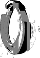
- the visor assembly 22 includes the chassis 31, various display elements, sensors and electronics, and a protective shield enclosure 37.
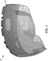
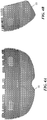
- the shield enclosure 37 is further illustrated according to one embodiment in Figures 3 , 4A and 4B .
- Figure 3 shows a rear perspective view of the shield enclosure 37.
- the shield enclosure 37 includes a rear shield 32 and a front shield 33.
- Figures 4A and 4B show, respectively, front and left side orthogonal views of the front shield 33 of the shield enclosure 37.
- the term “rear” generally refers to a part or surface that is closest to the user (wearer) of the HMD, while the term “front” generally refers to a corresponding part or surface that is farthest from the user.
- the display elements (not shown) are suspended within the visor assembly 22.
- the optics and sensors are also mounted to the chassis 31 within the shield enclosure 37.
- heat generated by the components within the visor simply 22 is conveyed by two flexible thermal conduits (not shown in Figure 2 ), one on the left side of the visor assembly 22 and one on the right side, to a heat dissipation structure in each of the side arms 24A and 24B.
- Each side arm 24A or 24B is a curved, elongated member that roughly follows the curvature of the headband 21.
- Each side arm 24A or 24B has a substantially rectangular cross-section.
- Each side arm 24A or 24B includes a heat dissipation structure that forms a thermal tunnel 25A or 25B that passes entirely through the side arm 24A or 24B, from the top surface to the bottom surface of the side arm, thereby providing a channel that allows air to low freely vertically through the body of the side arm 24A or 24B.
- the thermal tunnel 25A or 25B is thereby oriented such that the usual orientation of the device 1, when in use, favors natural rising air flow through the thermal tunnel 25A or 25B.
- the visor assembly 20 includes the chassis 31 and the shield enclosure 37 (see Figure 2 ).
- the chassis 31 is the structural component by which all of the display elements, optics, sensors and electronics are coupled to the rest of the HMD device 20.
- Figures 5A, 5B and 5C show, respectively, top, front and right-side views of the chassis 31, while Figure 6 shows a perspective view of the chassis 31.
- the chassis 31 can be formed of molded plastic or polymer, for example.
- the front surface 160 of the chassis 31 may include various fixtures (e.g., screw holes, raised flat surfaces, etc.) to which the sensor assembly (not shown) can be attached.
- the chassis 31 has screw holes (or other similar mounting fixtures) 161 by which a display assembly (described below) can be attached to it.
- the chassis 31 further has one or more fixtures by which at least one printed circuit board (PCB) 172 bearing the electronic components of the HMD 20 can be mounted, as shown in Figure 6.
- Figure 6 shows a front perspective view of the chassis 31 with a PCB 172 mounted to a top inner surface 176 of the chassis 31 (see Figures 5A, 5B and 5C ).
- the sensor assembly 111 includes a sensor frame 210 and various sensors mounted to it (e.g., head-tracking cameras, IR depth camera, visible-spectrum camera, and ambient light sensor) and IR light sources.
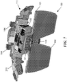
- Figure 7 shows a rear perspective view of the display assembly 130 (including optics assembly and a display engine 103) and sensor assembly 111, coupled to each other.
- the sensor frame 210 can attach to the top inner surface 176 of the chassis 31 (see Figures 5A, 5B and 5C ) via mounting points 184, for example, by screws or other fastening mechanism.
- the display assembly 130 includes a transparent waveguide carrier 101, on which are mounted multiple transparent waveguides 102, and a display engine 103.
- the display engine 103 contains one or more light-emission elements (e.g., light-emitting diodes (LEDs), not shown) for each of the left and right eye of the user.
- the display engine 103 is mounted to the waveguide carrier 101 at the center tab 51, such that light emitted by the display engine 103 is optically coupled to the waveguides 102, which convey the emitted light toward the user's eyes.
- the waveguide carrier 101 (with waveguides 102 and display engine 103 mounted to it) is mounted to the inside vertical surface of the chassis 31 through the nose bridge region 110 of the waveguide carrier 101, as further shown in Figure 8 .
- the sensor assembly 111 is mounted to the waveguide carrier 101 at the nose bridge region 110 and to the chassis 31.
- Figure 8 shows a front perspective view of how the combined sensor assembly 111 and display assembly 130 can be mounted to the chassis 31.
- Various components in the HMD device 20 generate heat during operation, including the display engine 103 and electronics mounted on the PCB 172.
- two flexible thermal conduits 82A and 82B conduct heat away from these components to the thermal tunnels 25A and 25B, respectively, in the side arms 24A and 24B, respectively ( Figure 2 ).
- Figure 8 shows a portion of the flexible thermal conduits 82A and 82B and the manner in which they can be thermally coupled to the heat generating components.
- the display engine 103 includes, or is coupled to, a metallic thermal plate 132, which conducts heat away from the display engine 103.
- Part of thermal plate 132 lies flat against a thermally conductive bracket 136. This configuration allows heat from the display engine 103 to be conducted onto flexible thermal conduit 82A via thermal bracket 136.
- An L-shaped thermal spreader 86 has a horizontal portion that is thermally coupled to PCB 172 and vertical portion (hidden by bracket 136) that is thermally coupled to the back of bracket 136.
- Brackets 136 and 137 clamp the anterior ends of flexible thermal conduits 82A and 82B, respectively, to the chassis 31; the opposite (posterior) ends of thermal conduits 82A and 82B can be coupled to the thermal tunnels 25A and 25B in side arms 24A and 24B, as discussed further below.
- Bracket 137 is an L-shaped (right-angle) bracket, having a horizontal upper portion and a vertical lower portion. The horizontal upper portion of bracket 137 lies flat against the PCB 172 on the inner horizontal surface of the chassis 31. More precisely, in the illustrated embodiment the horizontal upper portion of bracket 137 lies against a thin, flat heat spreader 88, which is sandwiched between the upper portion of bracket 137 and PCB 172. This configuration allows heat generated by electronic components on the PCB 172 to be conducted away from those components and onto flexible thermal conduit 82B, via heat spreader 88 and bracket 137.
- each of the flexible conduits 82A and 82B includes multiple layers of thin, flat, thermally conductive material, such as flexible graphite or very thin metal, stacked on top of each other.
- the layers of flexible conduits 82A and 82B may be made of, for example, eGRAF® SPREADERSHIELDTM SS500 Graphite, from GrafTech International.
- a flexible conduit 82A or 82B may consist of only a single layer.
- one or more layers of a flexible thermal conduit 82A or 82B can be made of a material other than graphite, such as a substrate loaded with graphene, or a thin layer of metal such as copper.
- a flexible thermal conduit 82A or 82B can be implemented in the form of a flexible heat pipe or vapor chamber.
- Heat generated by the display engine 103 or electronics on PCB 172 is conducted by flexible thermal conduits 82A and 82B away from the visor assembly 22 to the thermal tunnels 25A and 25B in the side arms 24A and 24B, respectively, as discussed further below, where the heat is dissipated into the air.
- Each side arm 24A or 24B can be coupled to the chassis 31 via a hinge assembly, as shown by example in Figure 9 , which allows the side arm 24A or 24B to flex relative to the visor assembly 22.
- Figure 9 shows the hinge assembly 92 connecting the left side arm 24B to the chassis 31 (the configuration is essentially identical for the right side arm). Note that the sensor assembly 111 and display assembly 130 are not included in the view of Figure 9 .
- the flexible thermal conduit 82B passes under the hinge assembly 92 and couples to a tunnel core (described further below), which is the heat dissipation component that forms the thermal tunnel 25B ( Figure 2 ), as described further below.
- Figure 10 shows a view similar to that of Figure 9 , but with hinge assembly 92 removed to provide a better view of thermal conduit 82B in the region of the hinge assembly 92.
- the layers of thermal conduit 82B are not attached to each other, at least in the region of the hinge assembly 92, which enables them to flex independently of each other when the side arm 24A or 24B is flexed relative to the chassis 31.
- the ability of the layers to flex independently of each other increases their durability with respect to repeated flexing. It can be seen, therefore, that the flexible thermal conduit 82A or 82B effectively forms a durable, lightweight "thermal hinge.”
- Figures 11 is another perspective view that further illustrates how thermal conduits 82A and 82B can be coupled to the chassis 31.
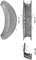
- Figure 12 is a left-side perspective view that further illustrates how the thermal tunnel 25A or 25B can be installed within the side arm 24A or 24B (in this case, the left side arm 24B) and coupled to a flexible thermal conduit 82A or 24B.
- the hinge 92 is also not included in the view of Figure 12 .
- the thermal tunnel 25A or 25B located in each side arm 24A or 24B will now be further described with reference to Figures 13 through 15 .
- the thermal tunnel 25A or 25B is formed by a heat dissipation component called the "tunnel core".
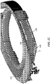
- Figure 13 shows a close-up left-side perspective view of the tunnel core 138 installed in the left side arm 24A, according to an embodiment.
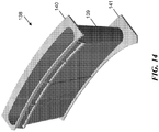
- Figure 14 shows a front-right perspective view of that same tunnel core 138 alone, and
- Figures 15A, 15B and 15C show top, front and left-side orthogonal views, respectively, of that same tunnel core 138.
- the tunnel core in the right side arm is simply the mirror image of tunnel core 138 shown in Figures 13 through 15 .
- the tunnel core 138 has a hollow main body 139 with flanges 140 and 141 extending from its top and bottom ends, respectively.
- the hollow center of the tunnel core 138 is shaped generally as a hollow oval cylinder, with flanges 140 and 141 forming the top and bottom surfaces, respectively.
- the interior surface 142 of the hollow tunnel core 138 forms part of the exterior surface of side arm 24B when tunnel core 138 is installed in side arm 24B.
- the interior surface 142 remains exposed to air and the fully assembled product and provides the surface area for dissipating heat into the air.
- the tunnel core 138 can be made of, for example, plastic, metal, or essentially any other rigid, thermally conductive material. If made of plastic, the tunnel core 138 can be formed by, for example, injection molding.
- the tunnel core 138 can be subdivided by ribs or partitions (not shown), that provide additional cooling surface area. These ribs or partitions can be formed as integral parts of the tunnel core 138, or they can be made as separate parts that are subsequently bonded to the tunnel core 138.
- the layers of the flexible thermal conduit 82B are thermally coupled to the tunnel core 138.
- the main body 139 of the tunnel core 138 can be wrapped at least partly (i.e., at least partially encircled) by one or more thicknesses of multi-layer, flexible, thermally conductive material, such as flexible graphite, to a thickness that extends approximately to the edges of the flanges 137 and 138.
- the layer(s) that is/are wrapped around the tunnel core 138 can be the continuation of one or more corresponding layer(s) of the flexible thermal conduit 82B.
- thermally conductive layers wrapped around the tunnel core 138 can be formed separately from thermal conduit 82B and then subsequently thermally coupled to thermal conduit 82B during product assembly (e.g., physically attached to it) in any suitable manner, such as by clamping.
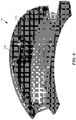
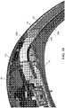
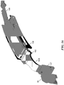
- Figures 16 through 18 further illustrate how the thermal tunnel can be thermally coupled to the flexible thermal conduit.
- Figures 16 and 17 are two corresponding perspective views illustrating how the left-side flexible thermal conduit 82B can be coupled to the tunnel core 138. Note that the corresponding components in the right side of the HMD 20 can be the same as (or mirror images of) those shown.
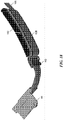
- Figure 18 shows a related perspective view, but with the tunnel core 138 omitted to facilitate visualization of the layers of thermally conductive material.
- the layers of flexible thermal conduit 82B are held together by a clamp 162 next to the anterior end of the tunnel core 138 (note that clamp is not shown in Figures 9 through 12 ).
- the main body 139 of the tunnel core 138 can be wrapped with (i.e., entirely encircled by) one or more layers 182 of flexible thermally conductive material, which may be but is not necessarily the same material as that of the thermal conduit 82B (e.g., flexible graphite).
- the layers of thermal conduit 82B are then laid in contact with the outboard side of the main body 139 (which has been wrapped with thermally conductive material).
- a thermally conductive adhesive (not shown) can be used to affix any of these layers to each other at the tunnel core 138 and/or to the main body 139 of the tunnel core 138.
- Such adhesive can be based on, for example, acrylics, silicones, epoxies, or any of various other thermosets.
- one or more layers of the thermal conduit 82B can be extended to continue posteriorly past the tunnel core 138 toward the rear of the HMD 20, as shown, where additional heat generating components may be installed (e.g., batteries, not shown); these extended layers 166 can act as a thermal pipe to transfer heat away from those additional components, forward to the tunnel core 138.
- thermally conductive layers wrapped around the tunnel core 138 may be rigid instead of flexible, such as very thin layers of metal, which are attached to the flexible thermal conduit 82A or 82B.
Landscapes
- Engineering & Computer Science (AREA)
- Physics & Mathematics (AREA)
- General Engineering & Computer Science (AREA)
- Thermal Sciences (AREA)
- Theoretical Computer Science (AREA)
- Mechanical Engineering (AREA)
- General Physics & Mathematics (AREA)
- Microelectronics & Electronic Packaging (AREA)
- Computer Hardware Design (AREA)
- Human Computer Interaction (AREA)
- Life Sciences & Earth Sciences (AREA)
- Sustainable Development (AREA)
- Optics & Photonics (AREA)
- Cooling Or The Like Of Electrical Apparatus (AREA)
- Chemical & Material Sciences (AREA)
- Materials Engineering (AREA)
- Condensed Matter Physics & Semiconductors (AREA)
- Power Engineering (AREA)
- Devices For Indicating Variable Information By Combining Individual Elements (AREA)
- Ceramic Engineering (AREA)
Claims (6)
- Kopfmontierte Anzeigevorrichtung (20), umfassend:eine Visoranordnung (22), beinhaltend eine Anzeigeanordnung (130), um ein Bild zu veranlassen, einem Anwender angezeigt zu werden, wobei die Visoranordnung einen elektronischen Bestandteil (103, 172) beinhaltet, der während des Betriebs Wärme erzeugt;eine Kopfanpassungsanordnung (21), flexibel mit einem Gelenkstück (92) an die Visoranordnung gekoppelt, durch die die kopfmontierte Anzeigevorrichtung auf dem Kopf des Anwenders getragen werden kann, wobei die Kopfanpassungsanordnung eine Wärmeabfuhrstruktur (138) beinhaltet; undeine mehrschichtige flexible Thermalleitung (82A, 82B), die von der Visoranordnung zu der Kopfanpassungsanordnung durchgeht, um durch den elektronischen Bestandteil erzeugte Wärme zu der Wärmeabfuhrstruktur in der Kopfanpassungsanordnung zu transportieren, dadurch gekennzeichnet, dass die mehrschichtige flexible Thermalleitung eine Vielzahl von flexiblen thermisch leitfähigen Schichten umfasst; unddie Vielzahl von flexiblen thermisch leitfähigen Schichten in einem Bereich, in dem die Kopfanpassungsanordnung an die Visoranordnung angelenkt ist, nicht aneinander befestigt sind, sodass die Vielzahl von flexiblen thermisch leitfähigen Schichten in der Lage sind, sich in dem Bereich des Gelenkstücks separat zu biegen.
- Kopfmontierte Anzeigevorrichtung nach Anspruch 1, wobei die Vielzahl von flexiblen thermisch leitfähigen Schichten eine Vielzahl von Schichten aus flexiblem Graphit umfasst.
- Kopfmontierte Anzeigevorrichtung nach einem von Anspruch 1 oder Anspruch 2, wobei die Vielzahl von flexiblen thermisch leitfähigen Schichten eine Vielzahl von Schichten aus Metall umfasst.
- Kopfmontierte Anzeigevorrichtung nach einem vorstehenden Anspruch, wobei:die Kopfanpassungsanordnung eine Vielzahl von gekrümmten, länglichen Seitenarmen (24A, 24B) beinhaltet, jeweils flexibel mittels eines separaten Gelenkstücks (92) einer Vielzahl von Gelenkstücken an ein unterschiedliches Ende der Visoranordnung gekoppelt, wobei jeder der Seitenarme eine Wärmeabfuhrstruktur (138) beinhaltet; undeine erste der Vielzahl von mehrschichtigen flexiblen Thermalleitungen (82A, 82B) an die Visoranordnung und an einen ersten der Seitenarme (24A, 24B), einem ersten der Vielzahl von Gelenkstücken benachbart, gekoppelt ist, und eine zweite der Vielzahl von mehrschichtigen flexiblen Thermalleitungen (82A, 82B) an die Visoranordnung und an einen zweiten der Seitenarme (24A, 24B), einem zweiten der Vielzahl von Gelenkstücken benachbart, gekoppelt ist, wobei jede der flexiblen Thermalleitungen konfiguriert ist, um durch mindestens einen der elektronischen Bestandteile erzeugte Wärme zu der Wärmeabfuhrstruktur in einem entsprechenden der Seitenarme zu transportieren, wobei jede der mehrschichtigen flexiblen Thermalleitungen eine Vielzahl von flachen, länglichen, flexiblen Thermalleitungsstreifen beinhaltet, die in einem Bereich proximal zu einem entsprechenden der Vielzahl von Gelenkstücken nicht aneinander befestigt sind, sodass die Vielzahl von Schichten in der Lage sind, sich in dem Bereich proximal zu dem entsprechenden der Vielzahl von Gelenkstücken zu biegen.
- Kopfmontierte Anzeigevorrichtung nach Anspruch 4, wobei die Vielzahl von flachen, länglichen, thermischen Leitungsstreifen eine Vielzahl von Schichten aus flexiblem Graphit umfassen.
- Kopfmontierte Anzeigevorrichtung nach Anspruch 4 oder Anspruch 5, wobei die Vielzahl von flachen, länglichen, thermischen Leitungsstreifen eine Vielzahl von Schichten aus Metall umfasst.
Priority Applications (1)
| Application Number | Priority Date | Filing Date | Title |
|---|---|---|---|
| EP21169613.3A EP3876023B1 (de) | 2015-01-20 | 2016-01-04 | Conduit thermique souple pour dispositif électronique |
Applications Claiming Priority (3)
| Application Number | Priority Date | Filing Date | Title |
|---|---|---|---|
| US201562105684P | 2015-01-20 | 2015-01-20 | |
| US14/705,893 US9545030B2 (en) | 2015-01-20 | 2015-05-06 | Flexible thermal conduit for an electronic device |
| PCT/US2016/012012 WO2016118311A1 (en) | 2015-01-20 | 2016-01-04 | Flexible thermal conduit for an electronic device |
Related Child Applications (2)
| Application Number | Title | Priority Date | Filing Date |
|---|---|---|---|
| EP21169613.3A Division EP3876023B1 (de) | 2015-01-20 | 2016-01-04 | Conduit thermique souple pour dispositif électronique |
| EP21169613.3A Division-Into EP3876023B1 (de) | 2015-01-20 | 2016-01-04 | Conduit thermique souple pour dispositif électronique |
Publications (2)
| Publication Number | Publication Date |
|---|---|
| EP3248047A1 EP3248047A1 (de) | 2017-11-29 |
| EP3248047B1 true EP3248047B1 (de) | 2021-05-26 |
Family
ID=56408899
Family Applications (3)
| Application Number | Title | Priority Date | Filing Date |
|---|---|---|---|
| EP16705319.8A Active EP3248047B1 (de) | 2015-01-20 | 2016-01-04 | Flexibler wärmeleiter für eine elektronische vorrichtung |
| EP21169613.3A Active EP3876023B1 (de) | 2015-01-20 | 2016-01-04 | Conduit thermique souple pour dispositif électronique |
| EP16704086.4A Active EP3247961B1 (de) | 2015-01-20 | 2016-01-14 | Wärmeabschwächungsstruktur für eine elektronische vorrichtung |
Family Applications After (2)
| Application Number | Title | Priority Date | Filing Date |
|---|---|---|---|
| EP21169613.3A Active EP3876023B1 (de) | 2015-01-20 | 2016-01-04 | Conduit thermique souple pour dispositif électronique |
| EP16704086.4A Active EP3247961B1 (de) | 2015-01-20 | 2016-01-14 | Wärmeabschwächungsstruktur für eine elektronische vorrichtung |
Country Status (4)
| Country | Link |
|---|---|
| US (3) | US9545030B2 (de) |
| EP (3) | EP3248047B1 (de) |
| CN (2) | CN107209382B (de) |
| WO (2) | WO2016118311A1 (de) |
Families Citing this family (90)
| Publication number | Priority date | Publication date | Assignee | Title |
|---|---|---|---|---|
| US10684687B2 (en) | 2014-12-03 | 2020-06-16 | Mentor Acquisition One, Llc | See-through computer display systems |
| US20150309534A1 (en) | 2014-04-25 | 2015-10-29 | Osterhout Group, Inc. | Ear horn assembly for headworn computer |
| WO2016094150A1 (en) | 2014-12-10 | 2016-06-16 | Graftech International Holdings Inc. | Flexible graphite sheet support structure and thermal management arrangement |
| US9545030B2 (en) | 2015-01-20 | 2017-01-10 | Microsoft Technology Licensing, Llc | Flexible thermal conduit for an electronic device |
| US9791704B2 (en) * | 2015-01-20 | 2017-10-17 | Microsoft Technology Licensing, Llc | Bonded multi-layer graphite heat pipe |
| US10028418B2 (en) | 2015-01-20 | 2018-07-17 | Microsoft Technology Licensing, Llc | Metal encased graphite layer heat pipe |
| US10108017B2 (en) | 2015-01-20 | 2018-10-23 | Microsoft Technology Licensing, Llc | Carbon nanoparticle infused optical mount |
| US10444515B2 (en) | 2015-01-20 | 2019-10-15 | Microsoft Technology Licensing, Llc | Convective optical mount structure |
| JP2017195514A (ja) * | 2016-04-20 | 2017-10-26 | キヤノン株式会社 | 頭部装着装置および把持装置 |
| US9964363B2 (en) * | 2016-05-24 | 2018-05-08 | Microsoft Technology Licensing, Llc | Heat pipe having a predetermined torque resistance |
| US10690936B2 (en) | 2016-08-29 | 2020-06-23 | Mentor Acquisition One, Llc | Adjustable nose bridge assembly for headworn computer |
| AU2017361096B2 (en) | 2016-11-16 | 2022-09-01 | Magic Leap, Inc. | Thermal management systems for wearable components |
| JP6921518B2 (ja) * | 2016-12-13 | 2021-08-18 | キヤノン株式会社 | 頭部装着型の表示装置 |
| USD864959S1 (en) | 2017-01-04 | 2019-10-29 | Mentor Acquisition One, Llc | Computer glasses |
| TWI622802B (zh) * | 2017-01-12 | 2018-05-01 | 宏碁股份有限公司 | 頭戴式顯示器 |
| US11112612B2 (en) * | 2017-01-24 | 2021-09-07 | Sony Corporation | Hinge mechanism and head-mounted display including this hinge mechanism |
| CN106682652B (zh) * | 2017-02-27 | 2020-06-23 | 上海大学 | 基于增强现实的结构表面病害巡检和分析方法 |
| CN106932905A (zh) * | 2017-02-27 | 2017-07-07 | 阿里巴巴集团控股有限公司 | 虚拟现实头戴设备 |
| US10206310B2 (en) * | 2017-04-07 | 2019-02-12 | Toyota Motor Engineering & Manufacturing North America, Inc. | Electronics assemblies incorporating three-dimensional heat flow structures |
| US10379583B2 (en) * | 2017-04-19 | 2019-08-13 | Facebook Technologies, Llc | System for discharging heat out of head-mounted display based on hybrid fan and heat pipe |
| US10359241B2 (en) * | 2017-05-31 | 2019-07-23 | Dell Products L.P. | Using a conductive sheet that includes graphene for thermal conductivity and for grounding |
| US10527355B2 (en) | 2017-06-13 | 2020-01-07 | Microsoft Technology Licensing, Llc | Devices, methods, and systems for thermal management |
| US10895751B1 (en) | 2017-06-29 | 2021-01-19 | Facebook Technologies, Llc | Adjustable facial-interface systems for head-mounted displays |
| US10045449B1 (en) | 2017-06-29 | 2018-08-07 | Oculus Vr, Llc | Adjustable facial-interface systems for head-mounted displays |
| CN110868967B (zh) | 2017-07-10 | 2024-10-29 | 奇跃公司 | 用于集成电子传感器与散热系统的方法和系统 |
| US10496130B1 (en) | 2017-07-18 | 2019-12-03 | Facebook Technologies, Llc | Adjustable facial-interface systems for head-mounted displays |
| US9989998B1 (en) * | 2017-07-18 | 2018-06-05 | Oculus Vr, Llc | Adjustable facial-interface systems for head-mounted displays |
| EP3646684B1 (de) * | 2017-09-07 | 2022-08-10 | Apple Inc. | Thermische regulierung für kopfmontierte anzeige |
| US10405467B2 (en) * | 2017-09-29 | 2019-09-03 | Google Llc | Integrated thermal door component for head mounted display |
| US10416735B2 (en) * | 2017-10-10 | 2019-09-17 | Google Llc | Heat pipe thermal component for cooling system |
| US10936031B2 (en) | 2018-04-13 | 2021-03-02 | Dell Products L.P. | Information handling system dynamic thermal transfer control |
| US10802555B2 (en) | 2018-04-13 | 2020-10-13 | Dell Products L.P. | Information handling system thermally conductive hinge |
| US10969841B2 (en) | 2018-04-13 | 2021-04-06 | Dell Products L.P. | Information handling system housing integrated vapor chamber |
| US10401926B1 (en) * | 2018-04-13 | 2019-09-03 | Dell Products L.P. | Information handling system housing thermal conduit interfacing rotationally coupled housing portions |
| US10579112B2 (en) * | 2018-04-13 | 2020-03-03 | Dell Products L.P. | Graphite thermal conduit spring |
| US10802556B2 (en) | 2018-04-13 | 2020-10-13 | Dell Products L.P. | Information handling system thermal fluid hinge |
| US10579113B2 (en) | 2018-04-13 | 2020-03-03 | Dell Products L.P. | Graphite thermal conduit spring |
| US10606083B2 (en) * | 2018-04-27 | 2020-03-31 | Microsoft Technology Licensing, Llc | Perspiration dissipating support assembly for head-mounted display devices |
| CN108732765A (zh) * | 2018-08-12 | 2018-11-02 | 苏州炫感信息科技有限公司 | 一种带有捕捉系统的虚拟现实眼镜 |
| US10551888B1 (en) | 2018-08-13 | 2020-02-04 | Dell Products L.P. | Skin transition thermal control for convertible information handling systems |
| JP7042194B2 (ja) * | 2018-08-31 | 2022-03-25 | 株式会社日立エルジーデータストレージ | 画像投射光学モジュールおよびヘッドマウントディスプレイ |
| US10823969B1 (en) * | 2018-12-14 | 2020-11-03 | Google Llc | Heat transfer through frame component of head-mounted device |
| US11163160B2 (en) | 2019-02-23 | 2021-11-02 | Microsoft Technology Licensing, Llc | HMD visor assembly |
| US11119544B1 (en) | 2019-03-07 | 2021-09-14 | Ricardo Perez | Mobile hardware heat dissipating and protection device |
| US11758702B2 (en) | 2019-04-30 | 2023-09-12 | Apple Inc. | Noise mitigation for head-mounted device |
| KR102734308B1 (ko) | 2019-05-31 | 2024-11-27 | 삼성전자주식회사 | 방열 부재를 포함하는 전자 장치 |
| US10806053B1 (en) | 2019-07-26 | 2020-10-13 | Microsoft Technology Licensing, Llc | Thermally conductive textiles for heat dissipation from wearable electronic devices |
| US10736244B1 (en) * | 2019-09-13 | 2020-08-04 | Microsoft Technology Licensing, Llc | Wearable electronic devices having multiple layers of electromagnetic spectrum specific paint for enhanced thermal performance |
| US10712791B1 (en) * | 2019-09-13 | 2020-07-14 | Microsoft Technology Licensing, Llc | Photovoltaic powered thermal management for wearable electronic devices |
| US10888037B1 (en) * | 2019-09-23 | 2021-01-05 | Microsoft Technology Licensing, Llc | Anti-fogging HMD utilizing device waste heat |
| CN110908121B (zh) * | 2019-12-06 | 2022-08-02 | Oppo广东移动通信有限公司 | 头戴式设备 |
| CN110967838B (zh) * | 2019-12-06 | 2022-06-07 | Oppo广东移动通信有限公司 | 头戴式设备 |
| CN110895370B (zh) * | 2019-12-06 | 2021-11-09 | Oppo广东移动通信有限公司 | 头戴式设备 |
| CN110824714B (zh) * | 2019-12-06 | 2022-04-01 | Oppo广东移动通信有限公司 | 用于头戴式设备的系带组件以及头戴式设备 |
| CN110967839B (zh) * | 2019-12-06 | 2022-08-05 | Oppo广东移动通信有限公司 | 保护壳体和头戴式设备 |
| CN110879475B (zh) * | 2019-12-06 | 2025-05-09 | Oppo广东移动通信有限公司 | 头戴式设备 |
| CN110908115B (zh) * | 2019-12-06 | 2022-06-07 | Oppo广东移动通信有限公司 | 头戴式设备 |
| CN110908116B (zh) * | 2019-12-06 | 2022-06-07 | Oppo广东移动通信有限公司 | 头戴式设备 |
| CN110967837B (zh) * | 2019-12-06 | 2022-06-07 | Oppo广东移动通信有限公司 | 头戴式设备 |
| CN110989170B (zh) * | 2019-12-06 | 2022-06-07 | Oppo广东移动通信有限公司 | 头戴式设备 |
| CN110927968A (zh) * | 2019-12-06 | 2020-03-27 | Oppo广东移动通信有限公司 | 头戴式设备 |
| US11751366B1 (en) | 2020-05-08 | 2023-09-05 | Apple Inc. | Heat dissipation for head-mountable device |
| CN111654777B (zh) * | 2020-06-29 | 2025-08-19 | 歌尔科技有限公司 | 头戴显示设备和头戴显示组件 |
| TWI735285B (zh) * | 2020-07-10 | 2021-08-01 | 研能科技股份有限公司 | 穿戴顯示裝置 |
| KR102878574B1 (ko) * | 2020-09-15 | 2025-10-30 | 삼성전자주식회사 | 방열 구조를 포함하는 웨어러블 전자 장치 |
| US11513573B2 (en) * | 2020-11-09 | 2022-11-29 | Meta Platforms Technologies, Llc | Active thermal management of a display panel |
| US11874471B2 (en) * | 2020-11-23 | 2024-01-16 | Samsung Electronics Co., Ltd. | Electronic device including heat radiating member |
| CN112764220B (zh) * | 2020-12-29 | 2022-11-11 | Oppo广东移动通信有限公司 | 可穿戴电子设备及其光机模组 |
| JP7604915B2 (ja) * | 2021-01-29 | 2024-12-24 | セイコーエプソン株式会社 | 画像表示装置 |
| CN116848957A (zh) | 2021-02-03 | 2023-10-03 | 三星电子株式会社 | 包括散热结构的可穿戴电子装置 |
| CN113311585A (zh) * | 2021-06-24 | 2021-08-27 | 深圳市仁禾智能实业有限公司 | 一种智能vr松紧绑带设备 |
| US11698536B2 (en) | 2021-07-30 | 2023-07-11 | Meta Platforms Technologies, Llc | Thermal management system for electronic device |
| US11782281B2 (en) | 2021-07-30 | 2023-10-10 | Meta Platforms Technologies, Llc | Thermal management system for electronic device |
| JP7760312B2 (ja) * | 2021-09-29 | 2025-10-27 | キヤノン株式会社 | 画像表示装置 |
| JP7718941B2 (ja) * | 2021-09-29 | 2025-08-05 | キヤノン株式会社 | 画像表示装置 |
| EP4357881A4 (de) * | 2021-10-19 | 2024-11-06 | Samsung Electronics Co., Ltd. | Elektronische vorrichtung mit lüftungsstruktur und wärmeableitungsstruktur |
| US11665856B2 (en) | 2021-10-26 | 2023-05-30 | Eagle Technology, Llc | Electronic device having flexible, heat conductive layer and associated methods |
| US11503701B1 (en) | 2021-10-26 | 2022-11-15 | Eagle Technology, Llc | Electronic device having heat transfer clamp and associated methods |
| US20230131070A1 (en) * | 2021-10-27 | 2023-04-27 | John Bernard Ardisana | Eyewear device with thermal vapor chamber |
| KR102631231B1 (ko) * | 2021-11-17 | 2024-01-31 | 주식회사 피앤씨솔루션 | 보호 커버를 구비한 증강현실 글래스 장치 및 증강현실 글래스 장치용 보호 커버 |
| US12328845B2 (en) * | 2021-12-20 | 2025-06-10 | Meta Platforms Technologies, Llc | Thermal conduit for electronic device |
| US12032171B1 (en) * | 2022-02-04 | 2024-07-09 | Meta Platforms Technologies, Llc | Thermal hinge system |
| TW202339602A (zh) * | 2022-02-04 | 2023-10-01 | 美商元平台技術有限公司 | 熱鉸鏈系統 |
| US12393052B1 (en) | 2022-02-04 | 2025-08-19 | Meta Platforms Technologies, Llc | Systems and methods for controlling thermal energy between hinged portions of electronic devices |
| WO2024034833A1 (ko) * | 2022-08-12 | 2024-02-15 | 삼성전자주식회사 | 열을 외부로 방출하기 위한 구조를 포함하는 전자 장치 |
| CN117916687A (zh) * | 2022-08-19 | 2024-04-19 | 谷歌有限责任公司 | 用于头戴式可穿戴设备的热管理 |
| CN119790720A (zh) * | 2022-08-29 | 2025-04-08 | 三星电子株式会社 | 包括包围多个集成电路的热管的电子装置 |
| US12453050B1 (en) * | 2022-11-29 | 2025-10-21 | Meta Platforms Technologies, Llc | Heat pipe including an integrated antenna |
| US20250264917A1 (en) * | 2023-01-09 | 2025-08-21 | Meta Platforms Technologies, Llc | Flexible hinge thermal architecture |
| US20250151225A1 (en) * | 2023-11-02 | 2025-05-08 | Channell Commercial Corporation | Vented pedestal housing |
Family Cites Families (63)
| Publication number | Priority date | Publication date | Assignee | Title |
|---|---|---|---|---|
| US4840225A (en) * | 1987-04-10 | 1989-06-20 | Digital Equipment Corporation | Heat exchange element and enclosure incorporating same |
| DE3738897A1 (de) | 1987-11-17 | 1989-05-24 | Standard Elektrik Lorenz Ag | Waermeleitendes verbindungselement fuer elektrische bauelemente |
| US5077637A (en) * | 1989-09-25 | 1991-12-31 | The Charles Stark Draper Lab., Inc. | Solid state directional thermal cable |
| SE469488B (sv) * | 1991-10-04 | 1993-07-12 | Christer Tennstedt | Termoelektriskt kylelement med flexibelt vaermeledningselement |
| US5218516A (en) | 1991-10-31 | 1993-06-08 | Northern Telecom Limited | Electronic module |
| US5486841A (en) * | 1992-06-17 | 1996-01-23 | Sony Corporation | Glasses type display apparatus |
| US5393951A (en) | 1993-02-01 | 1995-02-28 | Watteredge-Uniflex, Inc. | Flexible jumper and method of making |
| US5390734A (en) * | 1993-05-28 | 1995-02-21 | Lytron Incorporated | Heat sink |
| US5546099A (en) * | 1993-08-02 | 1996-08-13 | Virtual Vision | Head mounted display system with light blocking structure |
| EP0889346B1 (de) | 1993-08-20 | 2004-05-26 | Seiko Epson Corporation | Am Kopf montierte Bildanzeigevorrichtung |
| JPH09130705A (ja) | 1995-10-31 | 1997-05-16 | Olympus Optical Co Ltd | 頭部装着式映像表示装置 |
| USRE38382E1 (en) | 1996-04-04 | 2004-01-13 | Matsushita Electric Industrial Co., Ltd. | Heat sink and electronic device employing the same |
| US5781411A (en) | 1996-09-19 | 1998-07-14 | Gateway 2000, Inc. | Heat sink utilizing the chimney effect |
| US6075696A (en) * | 1997-11-06 | 2000-06-13 | Compaq Computer Corporation | Portable computer with flexible heat spreader plate structure therein |
| US6388640B1 (en) * | 1998-01-09 | 2002-05-14 | Canon Kabushiki Kaisha | Head mount display |
| JP2000010661A (ja) * | 1998-06-18 | 2000-01-14 | Mitsubishi Electric Corp | 携帯型情報処理装置および携帯型情報処理装置用カバー、卓上型情報処理装置 |
| US6532152B1 (en) | 1998-11-16 | 2003-03-11 | Intermec Ip Corp. | Ruggedized hand held computer |
| CN1129829C (zh) | 1999-07-26 | 2003-12-03 | 仁宝电脑工业股份有限公司 | 可展开型便携式计算机散热装置 |
| US6799628B1 (en) | 2000-07-20 | 2004-10-05 | Honeywell International Inc. | Heat exchanger having silicon nitride substrate for mounting high power electronic components |
| US6474074B2 (en) * | 2000-11-30 | 2002-11-05 | International Business Machines Corporation | Apparatus for dense chip packaging using heat pipes and thermoelectric coolers |
| EP1249868A1 (de) | 2001-04-12 | 2002-10-16 | ABB Schweiz AG | Kühlungseinrichtung für ein elektronisches Bauelement sowie Kühlsystem mit solchen Kühlungseinrichtungen |
| US6580608B1 (en) | 2001-12-21 | 2003-06-17 | Intel Corporation | Method and apparatus for thermally controlling multiple electronic components |
| TW592029B (en) | 2003-04-11 | 2004-06-11 | Delta Electronics Inc | Electronic apparatus with natural convection structure |
| US6826047B1 (en) | 2003-05-15 | 2004-11-30 | Uniwill Computer Corporation | Cool air-supplying device for a computer system |
| US7188484B2 (en) | 2003-06-09 | 2007-03-13 | Lg Electronics Inc. | Heat dissipating structure for mobile device |
| US9010645B2 (en) | 2003-06-13 | 2015-04-21 | Michael Arnouse | Portable computing system and portable computer for use with same |
| US20050168941A1 (en) * | 2003-10-22 | 2005-08-04 | Sokol John L. | System and apparatus for heat removal |
| US7469451B2 (en) * | 2003-12-18 | 2008-12-30 | Nokia Corporation | Hinge assembly |
| EP1622243B1 (de) * | 2004-07-30 | 2009-12-16 | Brose Fahrzeugteile GmbH & Co. KG, Würzburg | Elektromotor |
| US7319590B1 (en) | 2004-10-27 | 2008-01-15 | Raytheon Company | Conductive heat transfer system and method for integrated circuits |
| US7335983B2 (en) | 2005-12-16 | 2008-02-26 | Intel Corporation | Carbon nanotube micro-chimney and thermo siphon die-level cooling |
| US7898502B2 (en) * | 2006-01-30 | 2011-03-01 | Konica Minolta Holdings, Inc. | Image display apparatus and head-mounted display |
| CN101449374B (zh) * | 2006-06-08 | 2011-11-09 | 国际商业机器公司 | 高热传导性柔软片及其制造方法 |
| US7596956B2 (en) * | 2007-01-09 | 2009-10-06 | Lilke Harvey D | Refrigerated cabinet and cooling module for same |
| JP2008205041A (ja) | 2007-02-16 | 2008-09-04 | Toshiba Corp | 電子機器および熱伝導部材 |
| US7719856B2 (en) * | 2008-06-11 | 2010-05-18 | Adc Telecommunications, Inc. | Cam shaped hinges |
| US8957835B2 (en) * | 2008-09-30 | 2015-02-17 | Apple Inc. | Head-mounted display apparatus for retaining a portable electronic device with display |
| US20100167636A1 (en) | 2008-12-26 | 2010-07-01 | Anandaroop Bhattacharya | Active vents for cooling of computing device |
| EP2299582B1 (de) | 2009-09-18 | 2015-03-11 | SMA Solar Technology AG | Wechselrichter mit einem Gehäuse und darin angeordneten elektrischen und elektronischen Bauteilen |
| US7903405B1 (en) | 2009-09-18 | 2011-03-08 | Fisher-Rosemount Systems, Inc. | Electronic device enclosures having improved ventilation to dissipate heat |
| EP2327542A1 (de) * | 2009-11-27 | 2011-06-01 | Kerafol Keramische Folien GmbH | Mehrlagiges flexibles Wärmeleitlaminat |
| US20110149518A1 (en) * | 2009-12-18 | 2011-06-23 | Alcatel-Lucent Usa Inc. | Heat-transfer arrangement for enclosed circuit boards |
| KR20130000401A (ko) * | 2010-02-28 | 2013-01-02 | 오스터하우트 그룹 인코포레이티드 | 대화형 머리장착식 아이피스 상의 지역 광고 컨텐츠 |
| US20120212484A1 (en) | 2010-02-28 | 2012-08-23 | Osterhout Group, Inc. | System and method for display content placement using distance and location information |
| US9223134B2 (en) | 2010-02-28 | 2015-12-29 | Microsoft Technology Licensing, Llc | Optical imperfections in a light transmissive illumination system for see-through near-eye display glasses |
| US8482859B2 (en) | 2010-02-28 | 2013-07-09 | Osterhout Group, Inc. | See-through near-eye display glasses wherein image light is transmitted to and reflected from an optically flat film |
| US20130314303A1 (en) | 2010-02-28 | 2013-11-28 | Osterhout Group, Inc. | Ar glasses with user action control of and between internal and external applications with feedback |
| US20120000627A1 (en) | 2010-06-30 | 2012-01-05 | Tessera, Inc. | Electrostatic precipitator pre-filter for electrohydrodynamic fluid mover |
| US8451604B2 (en) | 2010-09-27 | 2013-05-28 | Intel Corporation | Chimney-based cooling mechanism for computing devices |
| US8952565B2 (en) | 2010-11-10 | 2015-02-10 | Flex-Cable | Deflection containing electrical conductor |
| CN102918444B (zh) | 2011-03-25 | 2015-12-23 | 松下电器产业株式会社 | 显示装置 |
| JP5614542B2 (ja) | 2011-03-28 | 2014-10-29 | 株式会社安川電機 | モータ制御装置 |
| US8611088B2 (en) * | 2011-11-16 | 2013-12-17 | Cooper Technologies Company | Mechanical heat pump for an electrical housing |
| US8913388B2 (en) * | 2012-01-18 | 2014-12-16 | Finisar Corporation | Thermally conductive flexible member for heat transfer |
| US9069166B2 (en) | 2012-02-29 | 2015-06-30 | Recon Instruments Inc. | Gaze detecting heads-up display systems |
| US9059129B2 (en) | 2012-09-27 | 2015-06-16 | Hamilton Sundstrand Corporation | Micro-die natural convection cooling system |
| US9271427B2 (en) * | 2012-11-28 | 2016-02-23 | Hamilton Sundstrand Corporation | Flexible thermal transfer strips |
| CN202975500U (zh) * | 2012-12-03 | 2013-06-05 | 温州市瓯海眼镜有限公司 | 太阳眼镜 |
| US9152190B2 (en) | 2012-12-11 | 2015-10-06 | Intel Corporation | Collapsible chimney for electronic device |
| KR102173141B1 (ko) | 2014-02-04 | 2020-11-02 | 삼성전자주식회사 | 히트 파이프를 포함하는 휴대 장치 |
| KR102186842B1 (ko) * | 2014-05-26 | 2020-12-04 | 엘지전자 주식회사 | 이동 단말기 |
| US9791704B2 (en) * | 2015-01-20 | 2017-10-17 | Microsoft Technology Licensing, Llc | Bonded multi-layer graphite heat pipe |
| US9545030B2 (en) * | 2015-01-20 | 2017-01-10 | Microsoft Technology Licensing, Llc | Flexible thermal conduit for an electronic device |
-
2015
- 2015-05-06 US US14/705,893 patent/US9545030B2/en active Active
- 2015-05-06 US US14/705,897 patent/US9585285B2/en active Active
-
2016
- 2016-01-04 EP EP16705319.8A patent/EP3248047B1/de active Active
- 2016-01-04 WO PCT/US2016/012012 patent/WO2016118311A1/en not_active Ceased
- 2016-01-04 EP EP21169613.3A patent/EP3876023B1/de active Active
- 2016-01-04 CN CN201680006201.XA patent/CN107209382B/zh not_active Expired - Fee Related
- 2016-01-14 WO PCT/US2016/013308 patent/WO2016118387A1/en not_active Ceased
- 2016-01-14 CN CN201680006206.2A patent/CN107209383B/zh not_active Expired - Fee Related
- 2016-01-14 EP EP16704086.4A patent/EP3247961B1/de active Active
- 2016-12-14 US US15/379,425 patent/US9986667B2/en active Active
Non-Patent Citations (1)
| Title |
|---|
| None * |
Also Published As
| Publication number | Publication date |
|---|---|
| EP3876023B1 (de) | 2023-09-20 |
| WO2016118387A1 (en) | 2016-07-28 |
| US9986667B2 (en) | 2018-05-29 |
| EP3248047A1 (de) | 2017-11-29 |
| US20160212889A1 (en) | 2016-07-21 |
| US9585285B2 (en) | 2017-02-28 |
| CN107209383A (zh) | 2017-09-26 |
| WO2016118311A1 (en) | 2016-07-28 |
| US20170099749A1 (en) | 2017-04-06 |
| US20160212879A1 (en) | 2016-07-21 |
| EP3247961A1 (de) | 2017-11-29 |
| EP3247961B1 (de) | 2022-02-09 |
| CN107209382A (zh) | 2017-09-26 |
| CN107209382B (zh) | 2020-05-05 |
| EP3876023A1 (de) | 2021-09-08 |
| CN107209383B (zh) | 2020-10-09 |
| US9545030B2 (en) | 2017-01-10 |
Similar Documents
| Publication | Publication Date | Title |
|---|---|---|
| EP3248047B1 (de) | Flexibler wärmeleiter für eine elektronische vorrichtung | |
| US9766461B2 (en) | Head-mounted display device with stress-resistant components | |
| US11231590B2 (en) | Heat transfer through frame component of head-mounted device | |
| US11058026B1 (en) | Air deflector for cooling system in a head-mounted device | |
| JP7272040B2 (ja) | 装着型表示装置 | |
| EP3239762B1 (de) | Kopfmontierte anzeige und greifvorrichtung | |
| US11397328B2 (en) | Wearable display device | |
| JP7298393B2 (ja) | 装着型表示装置 | |
| CN112255804A (zh) | 头戴式设备 | |
| JP2016116182A (ja) | ヘッドマウントディスプレイ | |
| JP7760312B2 (ja) | 画像表示装置 | |
| TWI885370B (zh) | 用於頭載式可穿戴裝置之熱管理 | |
| CN213814145U (zh) | 用于头戴式设备的壳体组件以及头戴式设备 |
Legal Events
| Date | Code | Title | Description |
|---|---|---|---|
| STAA | Information on the status of an ep patent application or granted ep patent |
Free format text: STATUS: THE INTERNATIONAL PUBLICATION HAS BEEN MADE |
|
| PUAI | Public reference made under article 153(3) epc to a published international application that has entered the european phase |
Free format text: ORIGINAL CODE: 0009012 |
|
| STAA | Information on the status of an ep patent application or granted ep patent |
Free format text: STATUS: REQUEST FOR EXAMINATION WAS MADE |
|
| 17P | Request for examination filed |
Effective date: 20170718 |
|
| AK | Designated contracting states |
Kind code of ref document: A1 Designated state(s): AL AT BE BG CH CY CZ DE DK EE ES FI FR GB GR HR HU IE IS IT LI LT LU LV MC MK MT NL NO PL PT RO RS SE SI SK SM TR |
|
| AX | Request for extension of the european patent |
Extension state: BA ME |
|
| DAV | Request for validation of the european patent (deleted) | ||
| DAX | Request for extension of the european patent (deleted) | ||
| GRAP | Despatch of communication of intention to grant a patent |
Free format text: ORIGINAL CODE: EPIDOSNIGR1 |
|
| STAA | Information on the status of an ep patent application or granted ep patent |
Free format text: STATUS: GRANT OF PATENT IS INTENDED |
|
| INTG | Intention to grant announced |
Effective date: 20210113 |
|
| GRAS | Grant fee paid |
Free format text: ORIGINAL CODE: EPIDOSNIGR3 |
|
| GRAA | (expected) grant |
Free format text: ORIGINAL CODE: 0009210 |
|
| STAA | Information on the status of an ep patent application or granted ep patent |
Free format text: STATUS: THE PATENT HAS BEEN GRANTED |
|
| RAP3 | Party data changed (applicant data changed or rights of an application transferred) |
Owner name: MICROSOFT TECHNOLOGY LICENSING, LLC |
|
| AK | Designated contracting states |
Kind code of ref document: B1 Designated state(s): AL AT BE BG CH CY CZ DE DK EE ES FI FR GB GR HR HU IE IS IT LI LT LU LV MC MK MT NL NO PL PT RO RS SE SI SK SM TR |
|
| REG | Reference to a national code |
Ref country code: GB Ref legal event code: FG4D |
|
| REG | Reference to a national code |
Ref country code: CH Ref legal event code: EP |
|
| REG | Reference to a national code |
Ref country code: DE Ref legal event code: R096 Ref document number: 602016058354 Country of ref document: DE |
|
| REG | Reference to a national code |
Ref country code: AT Ref legal event code: REF Ref document number: 1396803 Country of ref document: AT Kind code of ref document: T Effective date: 20210615 |
|
| REG | Reference to a national code |
Ref country code: IE Ref legal event code: FG4D |
|
| REG | Reference to a national code |
Ref country code: LT Ref legal event code: MG9D |
|
| REG | Reference to a national code |
Ref country code: AT Ref legal event code: MK05 Ref document number: 1396803 Country of ref document: AT Kind code of ref document: T Effective date: 20210526 |
|
| PG25 | Lapsed in a contracting state [announced via postgrant information from national office to epo] |
Ref country code: FI Free format text: LAPSE BECAUSE OF FAILURE TO SUBMIT A TRANSLATION OF THE DESCRIPTION OR TO PAY THE FEE WITHIN THE PRESCRIBED TIME-LIMIT Effective date: 20210526 Ref country code: LT Free format text: LAPSE BECAUSE OF FAILURE TO SUBMIT A TRANSLATION OF THE DESCRIPTION OR TO PAY THE FEE WITHIN THE PRESCRIBED TIME-LIMIT Effective date: 20210526 Ref country code: AT Free format text: LAPSE BECAUSE OF FAILURE TO SUBMIT A TRANSLATION OF THE DESCRIPTION OR TO PAY THE FEE WITHIN THE PRESCRIBED TIME-LIMIT Effective date: 20210526 Ref country code: BG Free format text: LAPSE BECAUSE OF FAILURE TO SUBMIT A TRANSLATION OF THE DESCRIPTION OR TO PAY THE FEE WITHIN THE PRESCRIBED TIME-LIMIT Effective date: 20210826 Ref country code: HR Free format text: LAPSE BECAUSE OF FAILURE TO SUBMIT A TRANSLATION OF THE DESCRIPTION OR TO PAY THE FEE WITHIN THE PRESCRIBED TIME-LIMIT Effective date: 20210526 |
|
| REG | Reference to a national code |
Ref country code: NL Ref legal event code: MP Effective date: 20210526 |
|
| RAP4 | Party data changed (patent owner data changed or rights of a patent transferred) |
Owner name: MICROSOFT TECHNOLOGY LICENSING, LLC |
|
| PG25 | Lapsed in a contracting state [announced via postgrant information from national office to epo] |
Ref country code: GR Free format text: LAPSE BECAUSE OF FAILURE TO SUBMIT A TRANSLATION OF THE DESCRIPTION OR TO PAY THE FEE WITHIN THE PRESCRIBED TIME-LIMIT Effective date: 20210827 Ref country code: IS Free format text: LAPSE BECAUSE OF FAILURE TO SUBMIT A TRANSLATION OF THE DESCRIPTION OR TO PAY THE FEE WITHIN THE PRESCRIBED TIME-LIMIT Effective date: 20210926 Ref country code: LV Free format text: LAPSE BECAUSE OF FAILURE TO SUBMIT A TRANSLATION OF THE DESCRIPTION OR TO PAY THE FEE WITHIN THE PRESCRIBED TIME-LIMIT Effective date: 20210526 Ref country code: PL Free format text: LAPSE BECAUSE OF FAILURE TO SUBMIT A TRANSLATION OF THE DESCRIPTION OR TO PAY THE FEE WITHIN THE PRESCRIBED TIME-LIMIT Effective date: 20210526 Ref country code: PT Free format text: LAPSE BECAUSE OF FAILURE TO SUBMIT A TRANSLATION OF THE DESCRIPTION OR TO PAY THE FEE WITHIN THE PRESCRIBED TIME-LIMIT Effective date: 20210927 Ref country code: NO Free format text: LAPSE BECAUSE OF FAILURE TO SUBMIT A TRANSLATION OF THE DESCRIPTION OR TO PAY THE FEE WITHIN THE PRESCRIBED TIME-LIMIT Effective date: 20210826 Ref country code: RS Free format text: LAPSE BECAUSE OF FAILURE TO SUBMIT A TRANSLATION OF THE DESCRIPTION OR TO PAY THE FEE WITHIN THE PRESCRIBED TIME-LIMIT Effective date: 20210526 Ref country code: SE Free format text: LAPSE BECAUSE OF FAILURE TO SUBMIT A TRANSLATION OF THE DESCRIPTION OR TO PAY THE FEE WITHIN THE PRESCRIBED TIME-LIMIT Effective date: 20210526 |
|
| PG25 | Lapsed in a contracting state [announced via postgrant information from national office to epo] |
Ref country code: NL Free format text: LAPSE BECAUSE OF FAILURE TO SUBMIT A TRANSLATION OF THE DESCRIPTION OR TO PAY THE FEE WITHIN THE PRESCRIBED TIME-LIMIT Effective date: 20210526 |
|
| PG25 | Lapsed in a contracting state [announced via postgrant information from national office to epo] |
Ref country code: SM Free format text: LAPSE BECAUSE OF FAILURE TO SUBMIT A TRANSLATION OF THE DESCRIPTION OR TO PAY THE FEE WITHIN THE PRESCRIBED TIME-LIMIT Effective date: 20210526 Ref country code: SK Free format text: LAPSE BECAUSE OF FAILURE TO SUBMIT A TRANSLATION OF THE DESCRIPTION OR TO PAY THE FEE WITHIN THE PRESCRIBED TIME-LIMIT Effective date: 20210526 Ref country code: EE Free format text: LAPSE BECAUSE OF FAILURE TO SUBMIT A TRANSLATION OF THE DESCRIPTION OR TO PAY THE FEE WITHIN THE PRESCRIBED TIME-LIMIT Effective date: 20210526 Ref country code: CZ Free format text: LAPSE BECAUSE OF FAILURE TO SUBMIT A TRANSLATION OF THE DESCRIPTION OR TO PAY THE FEE WITHIN THE PRESCRIBED TIME-LIMIT Effective date: 20210526 Ref country code: DK Free format text: LAPSE BECAUSE OF FAILURE TO SUBMIT A TRANSLATION OF THE DESCRIPTION OR TO PAY THE FEE WITHIN THE PRESCRIBED TIME-LIMIT Effective date: 20210526 Ref country code: RO Free format text: LAPSE BECAUSE OF FAILURE TO SUBMIT A TRANSLATION OF THE DESCRIPTION OR TO PAY THE FEE WITHIN THE PRESCRIBED TIME-LIMIT Effective date: 20210526 Ref country code: ES Free format text: LAPSE BECAUSE OF FAILURE TO SUBMIT A TRANSLATION OF THE DESCRIPTION OR TO PAY THE FEE WITHIN THE PRESCRIBED TIME-LIMIT Effective date: 20210526 |
|
| REG | Reference to a national code |
Ref country code: DE Ref legal event code: R097 Ref document number: 602016058354 Country of ref document: DE |
|
| PLBE | No opposition filed within time limit |
Free format text: ORIGINAL CODE: 0009261 |
|
| STAA | Information on the status of an ep patent application or granted ep patent |
Free format text: STATUS: NO OPPOSITION FILED WITHIN TIME LIMIT |
|
| 26N | No opposition filed |
Effective date: 20220301 |
|
| PG25 | Lapsed in a contracting state [announced via postgrant information from national office to epo] |
Ref country code: IS Free format text: LAPSE BECAUSE OF FAILURE TO SUBMIT A TRANSLATION OF THE DESCRIPTION OR TO PAY THE FEE WITHIN THE PRESCRIBED TIME-LIMIT Effective date: 20210926 Ref country code: AL Free format text: LAPSE BECAUSE OF FAILURE TO SUBMIT A TRANSLATION OF THE DESCRIPTION OR TO PAY THE FEE WITHIN THE PRESCRIBED TIME-LIMIT Effective date: 20210526 |
|
| PG25 | Lapsed in a contracting state [announced via postgrant information from national office to epo] |
Ref country code: IT Free format text: LAPSE BECAUSE OF FAILURE TO SUBMIT A TRANSLATION OF THE DESCRIPTION OR TO PAY THE FEE WITHIN THE PRESCRIBED TIME-LIMIT Effective date: 20210526 |
|
| PG25 | Lapsed in a contracting state [announced via postgrant information from national office to epo] |
Ref country code: MC Free format text: LAPSE BECAUSE OF FAILURE TO SUBMIT A TRANSLATION OF THE DESCRIPTION OR TO PAY THE FEE WITHIN THE PRESCRIBED TIME-LIMIT Effective date: 20210526 |
|
| REG | Reference to a national code |
Ref country code: CH Ref legal event code: PL |
|
| REG | Reference to a national code |
Ref country code: BE Ref legal event code: MM Effective date: 20220131 |
|
| PG25 | Lapsed in a contracting state [announced via postgrant information from national office to epo] |
Ref country code: LU Free format text: LAPSE BECAUSE OF NON-PAYMENT OF DUE FEES Effective date: 20220104 |
|
| PG25 | Lapsed in a contracting state [announced via postgrant information from national office to epo] |
Ref country code: BE Free format text: LAPSE BECAUSE OF NON-PAYMENT OF DUE FEES Effective date: 20220131 |
|
| PG25 | Lapsed in a contracting state [announced via postgrant information from national office to epo] |
Ref country code: LI Free format text: LAPSE BECAUSE OF NON-PAYMENT OF DUE FEES Effective date: 20220131 Ref country code: CH Free format text: LAPSE BECAUSE OF NON-PAYMENT OF DUE FEES Effective date: 20220131 |
|
| PG25 | Lapsed in a contracting state [announced via postgrant information from national office to epo] |
Ref country code: IE Free format text: LAPSE BECAUSE OF NON-PAYMENT OF DUE FEES Effective date: 20220104 |
|
| P01 | Opt-out of the competence of the unified patent court (upc) registered |
Effective date: 20230430 |
|
| PGFP | Annual fee paid to national office [announced via postgrant information from national office to epo] |
Ref country code: FR Payment date: 20231219 Year of fee payment: 9 |
|
| PG25 | Lapsed in a contracting state [announced via postgrant information from national office to epo] |
Ref country code: HU Free format text: LAPSE BECAUSE OF FAILURE TO SUBMIT A TRANSLATION OF THE DESCRIPTION OR TO PAY THE FEE WITHIN THE PRESCRIBED TIME-LIMIT; INVALID AB INITIO Effective date: 20160104 |
|
| PG25 | Lapsed in a contracting state [announced via postgrant information from national office to epo] |
Ref country code: MK Free format text: LAPSE BECAUSE OF FAILURE TO SUBMIT A TRANSLATION OF THE DESCRIPTION OR TO PAY THE FEE WITHIN THE PRESCRIBED TIME-LIMIT Effective date: 20210526 Ref country code: CY Free format text: LAPSE BECAUSE OF FAILURE TO SUBMIT A TRANSLATION OF THE DESCRIPTION OR TO PAY THE FEE WITHIN THE PRESCRIBED TIME-LIMIT Effective date: 20210526 |
|
| PG25 | Lapsed in a contracting state [announced via postgrant information from national office to epo] |
Ref country code: TR Free format text: LAPSE BECAUSE OF FAILURE TO SUBMIT A TRANSLATION OF THE DESCRIPTION OR TO PAY THE FEE WITHIN THE PRESCRIBED TIME-LIMIT Effective date: 20210526 |
|
| PG25 | Lapsed in a contracting state [announced via postgrant information from national office to epo] |
Ref country code: MT Free format text: LAPSE BECAUSE OF FAILURE TO SUBMIT A TRANSLATION OF THE DESCRIPTION OR TO PAY THE FEE WITHIN THE PRESCRIBED TIME-LIMIT Effective date: 20210526 |
|
| PGFP | Annual fee paid to national office [announced via postgrant information from national office to epo] |
Ref country code: DE Payment date: 20241218 Year of fee payment: 10 |
|
| PG25 | Lapsed in a contracting state [announced via postgrant information from national office to epo] |
Ref country code: FR Free format text: LAPSE BECAUSE OF NON-PAYMENT OF DUE FEES Effective date: 20250131 |
|
| PGFP | Annual fee paid to national office [announced via postgrant information from national office to epo] |
Ref country code: GB Payment date: 20251220 Year of fee payment: 11 |