EP3246451B2 - Verfahren und vorrichtung zum betreiben eines waschautomaten - Google Patents
Verfahren und vorrichtung zum betreiben eines waschautomaten Download PDFInfo
- Publication number
- EP3246451B2 EP3246451B2 EP17171063.5A EP17171063A EP3246451B2 EP 3246451 B2 EP3246451 B2 EP 3246451B2 EP 17171063 A EP17171063 A EP 17171063A EP 3246451 B2 EP3246451 B2 EP 3246451B2
- Authority
- EP
- European Patent Office
- Prior art keywords
- drum
- laundry
- washing machine
- washing
- heating
- Prior art date
- Legal status (The legal status is an assumption and is not a legal conclusion. Google has not performed a legal analysis and makes no representation as to the accuracy of the status listed.)
- Active
Links
Images


Classifications
-
- D—TEXTILES; PAPER
- D06—TREATMENT OF TEXTILES OR THE LIKE; LAUNDERING; FLEXIBLE MATERIALS NOT OTHERWISE PROVIDED FOR
- D06F—LAUNDERING, DRYING, IRONING, PRESSING OR FOLDING TEXTILE ARTICLES
- D06F33/00—Control of operations performed in washing machines or washer-dryers
- D06F33/30—Control of washing machines characterised by the purpose or target of the control
- D06F33/32—Control of operational steps, e.g. optimisation or improvement of operational steps depending on the condition of the laundry
- D06F33/36—Control of operational steps, e.g. optimisation or improvement of operational steps depending on the condition of the laundry of washing
-
- D—TEXTILES; PAPER
- D06—TREATMENT OF TEXTILES OR THE LIKE; LAUNDERING; FLEXIBLE MATERIALS NOT OTHERWISE PROVIDED FOR
- D06F—LAUNDERING, DRYING, IRONING, PRESSING OR FOLDING TEXTILE ARTICLES
- D06F2103/00—Parameters monitored or detected for the control of domestic laundry washing machines, washer-dryers or laundry dryers
- D06F2103/02—Characteristics of laundry or load
- D06F2103/04—Quantity, e.g. weight or variation of weight
-
- D—TEXTILES; PAPER
- D06—TREATMENT OF TEXTILES OR THE LIKE; LAUNDERING; FLEXIBLE MATERIALS NOT OTHERWISE PROVIDED FOR
- D06F—LAUNDERING, DRYING, IRONING, PRESSING OR FOLDING TEXTILE ARTICLES
- D06F2105/00—Systems or parameters controlled or affected by the control systems of washing machines, washer-dryers or laundry dryers
- D06F2105/28—Electric heating
-
- D—TEXTILES; PAPER
- D06—TREATMENT OF TEXTILES OR THE LIKE; LAUNDERING; FLEXIBLE MATERIALS NOT OTHERWISE PROVIDED FOR
- D06F—LAUNDERING, DRYING, IRONING, PRESSING OR FOLDING TEXTILE ARTICLES
- D06F37/00—Details specific to washing machines covered by groups D06F21/00 - D06F25/00
- D06F37/02—Rotary receptacles, e.g. drums
-
- D—TEXTILES; PAPER
- D06—TREATMENT OF TEXTILES OR THE LIKE; LAUNDERING; FLEXIBLE MATERIALS NOT OTHERWISE PROVIDED FOR
- D06F—LAUNDERING, DRYING, IRONING, PRESSING OR FOLDING TEXTILE ARTICLES
- D06F39/00—Details of washing machines not specific to a single type of machines covered by groups D06F9/00 - D06F27/00
- D06F39/04—Heating arrangements
-
- D—TEXTILES; PAPER
- D06—TREATMENT OF TEXTILES OR THE LIKE; LAUNDERING; FLEXIBLE MATERIALS NOT OTHERWISE PROVIDED FOR
- D06F—LAUNDERING, DRYING, IRONING, PRESSING OR FOLDING TEXTILE ARTICLES
- D06F39/00—Details of washing machines not specific to a single type of machines covered by groups D06F9/00 - D06F27/00
- D06F39/08—Liquid supply or discharge arrangements
- D06F39/083—Liquid discharge or recirculation arrangements
Definitions
- the invention relates to a method for operating a washing machine.
- Some laundry care appliances may have induction heating.
- a comfort smoothing function with a small amount of free liquor can also be provided below a drum casing of a laundry drum.
- heating by means of radiators can only be carried out if there is a free liquor available.
- the free liquor can be heated and heat can be transferred to the laundry when the liquor is exchanged.
- the DE 10 2014 208 514 A1 and the DE 10 2008 043281 A1 describes a laundry treatment device with induction heating.
- the EP 2 540 896 A1 describes a laundry treatment device with a flooding device.
- the object of the invention is to provide an improved method for operating a washing machine.
- the advantages that can be achieved with the invention consist, in addition to induction heating for washing machines and washer-dryers, in particular for washing machines and washer-dryers with a circulation function, for example, among other things, that water, detergent and energy are saved.
- heating without free liquor can also be made possible and damp laundry can be heated without additional consumption of additional water.
- switching the heating on and off in the heating step can be avoided, particularly when steam is used. No free liquor needs to be heated, which can lead to energy savings.
- This can be achieved in a cost-effective and structurally advantageous manner, with an electrical coil being arranged above or to the side of a tub and a drum being able to be heated evenly.
- the drum can be temperature-controlled, warmed up or heated up directly and as uniformly or evenly as possible.
- the drum can act as a heating element for tempering or heating laundry.
- the method can be carried out in connection with or using a non-claimed embodiment of a washing machine mentioned below.
- the eddy currents can be induced by means of an electrical signal applied to the at least one electrical coil.
- the automatic washing machine can be designed as a washing machine, a washer-dryer or the like.
- a drum wall can represent a drum shell.
- the at least one electric coil can be arranged outside of the drum.
- the drum may be rotatable relative to an electrical coil.
- the circulating step can be carried out once or repeatedly during the inducing step.
- Such an embodiment offers the advantage that by heating the drum wall combined with a circulation, a uniform heat distribution in the laundry can be realized in an energy- and water-saving manner, even with large batches of laundry.
- the circulating step can also be carried out once or repeatedly before and additionally or alternatively after the inducing step.
- the inducing step can be carried out repeatedly before, during and additionally or alternatively after the circulating step.
- a method for operating a washing machine having a drum for receiving laundry, the drum having at least one drum wall made of a ferromagnetic material, at least one electrical coil arranged adjacent to the drum and a flooding unit, the method has at least the following steps: applying an electrical signal to the at least one electrical coil to induce eddy currents in the at least one drum wall to heat the drum; and issuing a flood signal to the flood unit to circulate wash suds expelled from the laundry through the drum to flood the laundry with wash suds to saturate the laundry with wash suds.
- the method can be carried out in connection with or using an embodiment of a washing machine mentioned below.
- the method can in particular be executable by an embodiment of a device mentioned below or by a control unit.
- an electrical signal is applied which is suitable for generating a heating output which is dependent on the amount of laundry (280) loaded in the drum and on the temperature of the drum.
- the dispensing step can be carried out repeatedly before, during and additionally or alternatively after the applying step.
- Such an embodiment offers the advantage that by heating the drum wall combined with activated circulation, while saving energy and water, an even heat distribution can be realized in the laundry, even with large batches of laundry.
- a high-frequency electrical alternating voltage can be applied as an electrical signal in the application step in order to generate an alternating magnetic field with which the at least one drum wall can be applied.
- the electrical signal can be pulse width modulated.
- the approach presented here also creates a device for controlling an automatic washing machine, which is designed to carry out, control or implement the steps of a variant of a method presented here in corresponding devices.
- the device can have an embodiment of a washing machine which is not claimed below.
- the object on which the invention is based can also be achieved quickly and efficiently by this embodiment variant of the invention in the form of a device.
- the device can be designed to read in input signals and to determine and provide output signals using the input signals.
- An input signal can, for example, be read in via an input interface of the device Display sensor signal.
- An output signal may represent a control signal or a data signal that may be provided at an output interface of the device.
- the device can be designed to determine the output signals using a processing specification implemented in hardware or software.
- the device can include a logic circuit, an integrated circuit or a software module and can be implemented as a discrete component, for example, or can be comprised of a discrete component.
- a large contact area for heat transfer to the laundry can be provided by means of the drum as a heating element.
- heat can be transferred quickly to the laundry, so that the heating-up time can be kept short.
- all of the drum walls of the drum can be formed from the ferromagnetic material.
- the drum can be formed entirely of the ferromagnetic material. Such an embodiment offers the advantage that the drum can be heated uniformly and over a large area.
- the at least one electrical coil can be formed flat and additionally or alternatively from copper.
- the at least one electrical coil can be operated with high-frequency electrical alternating voltage.
- the washing machine can have a tub, it being possible for the drum to be arranged inside the tub.
- the at least one electrical coil can be arranged on the tub.
- the tub can be drum-shaped.
- the at least one electric coil can be arranged in the washing machine outside of a floor area arranged between the drum and a floor of the washing machine. More specifically, the at least one electric coil may be arranged at the top or side relative to the drum with respect to an orientation in an installed, set up or in-use state of the washing machine.
- Such an embodiment which is not claimed, offers the advantage that a simple construction of the washing machine and uncomplicated access to the at least one coil can be implemented.
- the automatic washing machine can also have at least one shielding element for shielding a magnetic field generated by the at least one electric coil in the direction away from the drum.
- at least one shielding element for shielding a magnetic field generated by the at least one electric coil in the direction away from the drum.
- the at least one shielding element can have at least one ferrite plate and additionally or alternatively at least one aluminum plate.
- magnetic fields that arise can be shielded by means of ferrite plates, with any remaining magnetic fields being additionally shielded by means of an aluminum plate, with ferrite plates being able to be arranged between the drum and the aluminum plate.
- FIG 1 shows a schematic representation of a washing machine 100 for washing laundry according to an embodiment of the invention.
- the automatic washing machine 100 is designed here as a washing machine, a washer-dryer or the like.
- the washing machine 100 can also be referred to as a laundry treatment device or laundry care device.
- the washing machine 100 has a drum 110 for receiving the laundry.
- the drum 110 is rotatably mounted in the automatic washing machine 100 .
- At least one wall or drum wall of the drum 110 is formed from a ferromagnetic material.
- all of the drum walls of drum 110 are formed from the ferromagnetic material.
- the automatic washing machine 100 has, for example, only one electric coil 120 .
- the electrical coil 120 is used to induce eddy currents in the at least one drum wall of the drum 110 .
- the drum 110 is heated by the eddy currents.
- the electrical coil 120 is arranged adjacent to the drum 110 so that an alternating magnetic field generated by the coil 120 acts on at least one section of the drum 110 .
- the electric coil 120 is arranged outside of a floor area in the washing machine 100 which is arranged between the drum 110 and a floor of the washing machine 100 .
- the electrical coil 120 is shaped as a flat coil or planar.
- the electrical coil has 120 turns of copper.
- the automatic washing machine 100 can have a plurality of electrical coils 120 .
- the washing machine 100 has according to in figure 1 shown exemplary embodiment of the invention also has a flooding unit 130 .
- the flooding unit 130 is designed to circulate wash suds through the drum 110 for flooding the laundry with wash suds.
- the circulation unit 130 is designed, for example, to circulate the wash suds intermittently through the drum 110 in order to keep the laundry in a damp state.
- the washing machine 100 also has a tub 140 on. Inside the tub 140, the drum 110 is arranged. In this case, the electric coil 120 is arranged on the tub 140 , for example. A wall section of the tub 140 is arranged between the electric coil 120 and the drum 110 .
- the washing machine 100 also has only one shielding element 150 by way of example.
- the shielding element 150 is designed to shield or dampen a magnetic field or magnetic field generated by the electric coil 120 in the direction away from the drum 110 .
- the electrical coil 120 is arranged between the shielding element 150 and the drum 110 or the tub 140 .
- the washing machine 100 also has an operating device 160 or device 160 for operating the washing machine 100 .
- the operating device 160 is, for example, a control unit or the like.
- the shielding element 150 is arranged between the electric coil 120 and the operating device 160, so that components of the operating device 160 that are sensitive to magnetic fields can be protected by the shielding element 150 from the magnetic fields generated by the coil 120.
- the operating device 160 has an application device 162 .
- the application device 162 is designed to apply an electrical signal 172 for inducing eddy currents in the at least one drum wall to heat the drum 110 to the electrical coil 120 .
- the electrical signal 172 can be a high-frequency alternating electrical voltage.
- the operating device 160 has according to in figure 1 shown embodiment of the invention also has an output device 164.
- the output device 164 is designed to apply a flooding signal 174 to the flooding unit 130 in order to cause wash suds to be circulated through the drum for flooding the laundry with wash suds.
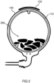
- figure 2 shows a schematic representation of a section of a washing machine according to an embodiment of the invention.
- figure 2 shows the section of the washing machine in a schematic sectional view.
- the in figure 2 shown washing machine from the washing machine figure 1 .
- the drum 110, the electric coil 120 and the tub 140 are shown.
- Laundry 280 is also shown in the drum 110 by way of example.
- the electrical coil 120 has according to in figure 2 shown embodiment of the invention has a curved sectional profile. A curvature of the electrical coil 120 follows a curvature of the drum 110 and the tub 140.
- FIG 2 shows figure 2 a schematic diagram of induction heating for a washing machine.
- the electrical coil 120 is mounted on an upper side or on the side of the tub 140 in relation to an orientation in a mounted state or operating state.
- the drum 110 can be inductively heated by means of the electrical coil 120 .
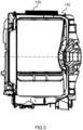
- figure 3 shows a schematic representation of a section of a washing machine according to an embodiment of the invention. While showing figure 3 the section of the washing machine in a sectional view.
- the inside figure 3 washing machine shown corresponds to or resembles the washing machine figure 1 .
- From the washing machine are in figure 3 here the electric coil 120 and the tub 140 are shown.
- the electrical coil 120 is arranged on the tub 140 .
- figure 4 shows a flowchart of a method 400 for washing laundry according to an embodiment of the invention.
- the method 400 for washing is in connection with the automatic laundromat figure 1 , figure 2 or. figure 3 or a similar washing machine executable.
- the method 400 for washing has a step 410 of inducing eddy currents in the at least one drum wall to heat the drum.
- the method 400 of washing also includes a step 420 of circulating wash suds through the drum to flood the laundry with wash suds.
- the circulating step 420 can be carried out before, during and/or after the inducing step 410 .
- the step 420 of circulating can also be carried out repeatedly.
- step 410 of inducing and step 420 of circulating can be carried out, for example, parallel to one another and/or at different times and/or at least temporarily intermittently.
- FIG 5 shows a flowchart of a method 500 for operating according to an embodiment of the invention.
- the method 500 can be implemented to operate a washing machine. More specifically, the method 500 is executable to turn off the automatic laundromat figure 1 , figure 2 or. figure 3 or to operate a similar washing machine.
- the method 500 of operating in conjunction with the automatic laundromat is over figure 1 , figure 2 or. figure 3 or a similar washing machine executable.
- the method 500 for operating by means of or using the operating device is off figure 1 or a similar operating device.
- the operating device is off figure 1 configured to perform method 500 of operating.
- the method 500 for operating has a step 510 of applying an electrical signal to the electrical coil.
- the electrical signal applied causes eddy currents to be induced in the at least one drum wall by means of the electrical coil in order to heat the drum.
- the electrical signal is, for example, a high-frequency electrical AC voltage.
- the high-frequency electrical AC voltage is applied as an electrical signal, for example, in order to generate an alternating magnetic field with which the at least one drum wall of the drum is applied.
- the electrical signal is pulse-width modulated depending on a load of laundry in the drum or a duty cycle or duty cycle of the electrical signal is modulated depending on the load.
- the method 500 for operating also has a step 520 of outputting a flooding signal to a flooding unit.
- the flooding signal is output or made available for output to the flooding unit.
- the flood signal is adapted, when used by the flood unit, to cause wash suds to be circulated through the drum to flood the laundry with wash suds.
- step 520 of dispensing can be carried out before, during and/or after step 510 of creating.
- the step 520 of outputting can also be carried out repeatedly.
- step 510 of applying and step 520 of outputting can be carried out, for example, in parallel with one another and/or at different times and/or at least temporarily intermittently.
- FIG. 6 shows a flow diagram of a process 600 for washing according to an embodiment of the invention.
- the process 600 for washing is off in connection with the washing machine figure 1 , figure 2 or. figure 3 or a similar washing machine executable.
- the process 600 for washing associated with the method 400 for washing is off figure 4 and/or with the method 500 for operating figure 5 or similar procedures.
- a block 602 laundry is brought to a target saturation with wash suds or to a target amount of water. Subsequently, in a block 604, a flooding is started in order to bring residual water into the laundry. As a result, there is no longer any free liquor and the water or washing lye is completely or at least approximately completely absorbed in the batch of laundry.
- an induction in particular with a setting of a so-called booster operation, for example with an output of 2.5 kilowatts or the like, is started until a temperature rise of 10 Kelvin or a starting energy calculated as a function of the tied fleet is reached.
- the so-called booster operation can be selected to quickly get up to temperature.
- the induction is adjusted in normal operation.
- the output can be set depending on the load so that the heating energy that is brought in can be optimally absorbed by the laundry.
- heating energy of, for example, 1.0 kilowatts can be introduced with a small load, heating energy of, for example, 1.5 kilowatts with a medium load, and heating energy of, for example, 2.0 kilowatts with a large load.
- a flow of heat can be increased by the flooding, and heat can also enter a core of the laundry.
- circulation is carried out continuously until a target temperature Tsoll is reached.
- the flooding can be carried out, for example, every 5 minutes, with a medium load, for example, every 2 minutes, and with a large load, for example, every 30 seconds.
- a rotational speed of the drum is hereby adapted to the circulation sequences or to the loading. If a current speed is greater than a circulation speed n circulation , flooded.
- the circulation speed n circulation can be in the range from 60 to 100 rpm , for example. Speeds of more than 60 rpm can expel lye, which can then be flooded or circulated to flood.
- the induction mode is then switched off in a block 614 when the target temperature Tsoll has been reached. Thereafter, the process 600 proceeds to a decision block 616 where it is checked whether or not a post heat function is active. If the decision block 616 determines that the post heat function is active, the process 600 proceeds to a block 618 .
- the induction mode is switched over to a post-heating mode.
- a power level is set as a function of the target temperature Tsoll.
- a power input can be between 0.3 kilowatts and 0.7 kilowatts, for example.
- the circulation can be carried out continuously, for example every minute, regardless of the load if a current speed is over 60 min -1 .
- An energy requirement for maintaining a temperature depends on the temperature level, with the load quantity or laundry load playing a subordinate role.
- a further program or sequence of a washing program is processed. If it is determined at decision block 616 that the post heat function is not active, then the process 600 transfers directly from decision block 616 to block 622.
- An induction heating is implemented, in which the at least one drum wall or drum casing of the drum 110 can be heated or tempered by means of the electrical coil 120 .
- heating energy can be supplied at an early stage even in an operating mode of the automatic washing machine 100 referred to as stepped refueling.
- the drum 110 is warmed up for the actual heating process. After the laundry 280 is sufficiently damp, the actual heating process begins.
- the laundry 280 is, for example, in a normal washing cycle, z. B. a ramp rhythm or the like rotated. In phases, the wash 280 optionally becomes short thrown at. Such an expulsion of lye activates a pressure-dependent flooding.
- the heat from the drum wall or the drum casing is transferred to the suds and is brought directly into the laundry 280 by the introduction of the washing suds by means of circulation.
- This process can be carried out depending on the load.
- the larger a batch or batch of laundry the more often the suds can be expelled by spinning or the like.
- a speed of the drum 110 can be set to be increased. In the case of small batches of laundry, there is no need to spin the laundry completely because there is sufficient contact between the laundry 280 and the drum 110 even with normal washing rhythms.
- the circulation can be activated, for example, once a minute or the like.
- the circulation can be activated every two minutes or the like, for example.
- the flooding can optionally be omitted.
- a permanent direct contact of the drum 110 with the items to be washed or the laundry 280 is given at a drum speed equal to or higher than the so-called contact speed.
- a power output targeted for the process step can be set by means of the electrical signal 172 through a regulated power output of the induction heating, similar to a hob.
- the output can be set in such a way that the laundry 280 can absorb the heating energy that has been introduced.
- a load of laundry 280 can also be taken into account.
- a heating output of, for example, 1.2 kilowatts can be introduced with a small load, a heating output of, for example, 1.8 kilowatts with a medium load, and a heating output of, for example, 2.1 kilowatts with a large load.
- a heating output of 1.0 kilowatts, for example, can be introduced for post-heating, and a heating output of 3.0 kilowatts, for example, can be introduced for rapid heating (booster).
- a washing drum 110 or drum 110 with a drum wall made of ferromagnetic material is used for such an induction heating.
- a flat copper coil 120 that can be operated, for example, with high-frequency alternating voltage is attached outside the drum wall. This generates an alternating magnetic field, which generates eddy currents in the drum wall. The drum wall heats up due to Joule losses. In this way, the entire drum is heated by the induction heating.
- the resulting magnetic fields can be shielded using ferrite plates.
- the remaining magnetic fields can additionally be shielded by an aluminum plate adjacent to the ferrite plates.
- the ferrite plates can be arranged between the aluminum plate and the electric coil 120 .
- the ferrite plates and the aluminum plate represent shielding elements 150 of the washing machine 100.
- a washing method with active circulation in which the laundry 280 is at least temporarily only brought into a damp state, heating can be made possible before, during and/or after the respective water supply processes, a so-called graduated refueling. In this way, warming can already be achieved with a staged refueling. Furthermore, for example, a cumbersome heating process by means of steam can be avoided. In addition, however, a steam smoothing function can be implemented quickly and reliably.
Landscapes
- Engineering & Computer Science (AREA)
- Textile Engineering (AREA)
- Detail Structures Of Washing Machines And Dryers (AREA)
- Control Of Washing Machine And Dryer (AREA)
Priority Applications (1)
| Application Number | Priority Date | Filing Date | Title |
|---|---|---|---|
| PL17171063.5T PL3246451T5 (pl) | 2016-05-19 | 2017-05-15 | Sposób i urządzenie do obsługi pralki automatycznej |
Applications Claiming Priority (4)
| Application Number | Priority Date | Filing Date | Title |
|---|---|---|---|
| DE102016109200 | 2016-05-19 | ||
| DE102016109178 | 2016-05-19 | ||
| DE102016109172 | 2016-05-19 | ||
| DE102016110550.3A DE102016110550B4 (de) | 2016-05-19 | 2016-06-08 | Verfahren zum Waschen von Wäsche, Verfahren und Vorrichtung zum Betreiben eines Waschautomaten und Waschautomat zum Waschen von Wäsche |
Publications (3)
| Publication Number | Publication Date |
|---|---|
| EP3246451A1 EP3246451A1 (de) | 2017-11-22 |
| EP3246451B1 EP3246451B1 (de) | 2020-06-24 |
| EP3246451B2 true EP3246451B2 (de) | 2023-03-29 |
Family
ID=58709368
Family Applications (1)
| Application Number | Title | Priority Date | Filing Date |
|---|---|---|---|
| EP17171063.5A Active EP3246451B2 (de) | 2016-05-19 | 2017-05-15 | Verfahren und vorrichtung zum betreiben eines waschautomaten |
Country Status (2)
| Country | Link |
|---|---|
| EP (1) | EP3246451B2 (pl) |
| PL (1) | PL3246451T5 (pl) |
Families Citing this family (8)
| Publication number | Priority date | Publication date | Assignee | Title |
|---|---|---|---|---|
| CN115418828A (zh) * | 2018-02-22 | 2022-12-02 | Lg电子株式会社 | 洗衣装置及其控制方法 |
| KR102550766B1 (ko) * | 2018-02-22 | 2023-07-04 | 엘지전자 주식회사 | 의류처리기기 및 의류처리기기의 제어방법 |
| KR102647359B1 (ko) * | 2018-10-16 | 2024-03-14 | 엘지전자 주식회사 | 세탁장치 및 이의 제어방법 |
| KR102525026B1 (ko) * | 2018-02-23 | 2023-04-24 | 엘지전자 주식회사 | 세탁기 및 세탁기의 제어방법 |
| WO2019223849A1 (en) * | 2018-05-21 | 2019-11-28 | Electrolux Appliances Aktiebolag | Laundry drier |
| KR20200042820A (ko) * | 2018-10-16 | 2020-04-24 | 엘지전자 주식회사 | 세탁장치 및 이의 제어방법 |
| KR20200042819A (ko) * | 2018-10-16 | 2020-04-24 | 엘지전자 주식회사 | 세탁장치 및 이의 제어방법 |
| US11598042B2 (en) | 2019-03-28 | 2023-03-07 | Whirlpool Corporation | Laundry treating appliance with induction heat |
Citations (4)
| Publication number | Priority date | Publication date | Assignee | Title |
|---|---|---|---|---|
| JPS6158694A (ja) † | 1984-08-31 | 1986-03-25 | 松下電器産業株式会社 | 衣類乾燥機 |
| JPH08252393A (ja) † | 1995-03-16 | 1996-10-01 | Matsushita Electric Ind Co Ltd | 洗濯機 |
| JP3475294B2 (ja) † | 2000-11-08 | 2003-12-08 | 株式会社コメック | 米飯の連続炒め装置及び方法 |
| JP2004135998A (ja) † | 2002-10-21 | 2004-05-13 | Nippon Kouatsu Electric Co | ドラム式衣類乾燥機 |
Family Cites Families (4)
| Publication number | Priority date | Publication date | Assignee | Title |
|---|---|---|---|---|
| DE102008043281A1 (de) | 2008-10-29 | 2010-05-06 | BSH Bosch und Siemens Hausgeräte GmbH | Hausgerät zur Pflege von Wäschestücken mit einer Heizvorrichtung und Verfahren zum Heizen einer Waschlauge und/oder von Wäschestücken in einer Trommel eines Hausgeräts |
| TR201005181A2 (tr) | 2010-06-25 | 2010-12-21 | Vestel Beyaz E�Ya Sanay� Ve T�Caret Anon�M ��Rket�@ | Bir indüksiyon ısıtma sistemi |
| EP2540896B1 (en) * | 2011-06-30 | 2016-04-13 | Electrolux Home Products Corporation N.V. | Method for washing laundry in a laundry washing machine |
| DE102014208514A1 (de) | 2014-05-07 | 2015-11-12 | BSH Hausgeräte GmbH | Wäschebehandlungsgerät mit Induktionsheizung |
-
2017
- 2017-05-15 EP EP17171063.5A patent/EP3246451B2/de active Active
- 2017-05-15 PL PL17171063.5T patent/PL3246451T5/pl unknown
Patent Citations (4)
| Publication number | Priority date | Publication date | Assignee | Title |
|---|---|---|---|---|
| JPS6158694A (ja) † | 1984-08-31 | 1986-03-25 | 松下電器産業株式会社 | 衣類乾燥機 |
| JPH08252393A (ja) † | 1995-03-16 | 1996-10-01 | Matsushita Electric Ind Co Ltd | 洗濯機 |
| JP3475294B2 (ja) † | 2000-11-08 | 2003-12-08 | 株式会社コメック | 米飯の連続炒め装置及び方法 |
| JP2004135998A (ja) † | 2002-10-21 | 2004-05-13 | Nippon Kouatsu Electric Co | ドラム式衣類乾燥機 |
Also Published As
| Publication number | Publication date |
|---|---|
| EP3246451B1 (de) | 2020-06-24 |
| EP3246451A1 (de) | 2017-11-22 |
| PL3246451T3 (pl) | 2020-11-16 |
| PL3246451T5 (pl) | 2023-05-15 |
Similar Documents
| Publication | Publication Date | Title |
|---|---|---|
| EP3246451B2 (de) | Verfahren und vorrichtung zum betreiben eines waschautomaten | |
| EP2350376B1 (de) | Hausgerät zur pflege von wäschestücken mit einer heizvorrichtung und verfahren zum heizen einer waschlauge und/oder von wäschestücken in einer trommel eines hausgeräts | |
| EP3004448B1 (de) | Verfahren zum betrieb einer waschmaschine mit einer verbesserten restfeuchte der wäsche sowie hierzu geeignete waschmaschine | |
| DE69602915T2 (de) | Verfahren zum Waschen von Wäsche in einer Haushaltwaschmaschine | |
| DE102008009036A1 (de) | Steuerverfahren für eine kommerzielle Waschmaschine | |
| DE102010016454A1 (de) | Wäschebehandlungsgerät mit kontrollierter mechanischer Energie | |
| EP3276072B1 (de) | Verfahren zum behandeln von wäsche in einer wäschebehandlungsmaschine und wäschebehandlungsmaschine zum behandeln von wäsche | |
| DE102014107910A1 (de) | Wäschebehandlungsvorrichtung mit ferngesteuertem Luftstrom und Verfahren zum Betreiben selbiger | |
| EP2158350B1 (de) | Verfahren zur behandlung von wäschestücken sowie hierzu geeignete waschmaschine | |
| DE102016110550B4 (de) | Verfahren zum Waschen von Wäsche, Verfahren und Vorrichtung zum Betreiben eines Waschautomaten und Waschautomat zum Waschen von Wäsche | |
| EP2115206B1 (de) | Verfahren zum waschen von wäschestücken in einem programmgesteuerten hausgerät, sowie solches hausgerät | |
| EP3375930A2 (de) | Verfahren zum trocknen von wäsche, steuerverfahren und steuervorrichtung zum steuern eines trocknungsvorgangs und waschtrockner | |
| DE102017219042A1 (de) | Wäschepflegegerät mit einer Steuerung | |
| DE4421848A1 (de) | Verfahren zum Betreiben einer Waschmaschine | |
| DE4030794C2 (de) | Vorrichtung zur Regelung der Wasch- und Trockentemperatur für kombinierte Wasch- und Wäschetrocknermaschinen | |
| DE102014214348B4 (de) | Wäschepflegegerät mit einer Laugenerzeugungseinrichtung | |
| EP3246452B1 (de) | Waschautomat zum waschen von wäsche | |
| EP2792780B1 (de) | Verfahren zum Waschen von Wäsche in einer Waschmaschine | |
| DE102013106097B4 (de) | Verfahren zum Betreiben einer Waschmaschine und Waschmaschine | |
| EP4361335B1 (de) | Wasch- und trocknungssystem und verfahren zum steuern eines wasch- und trockenvorgangs | |
| EP0031016A1 (de) | Verfahren zum Waschen von Wäsche | |
| DE102017103498A1 (de) | Verfahren zum Trocknen von Wäsche, Steuerverfahren und Steuervorrichtung zum Steuern eines Trocknungsvorgangs und wasserführendes Haushaltgerät zur Wäschebehandlung | |
| DE3523824C2 (pl) | ||
| DE102008050689B4 (de) | Verfahren zum Steuern einer Waschmaschine | |
| DE102020131598A1 (de) | Verfahren zum Betreiben eines Textilbehandlungsgeräts mit mindestens zwei Heizelementen, Steuereinrichtung und Textilbehandlungsgerät |
Legal Events
| Date | Code | Title | Description |
|---|---|---|---|
| PUAI | Public reference made under article 153(3) epc to a published international application that has entered the european phase |
Free format text: ORIGINAL CODE: 0009012 |
|
| STAA | Information on the status of an ep patent application or granted ep patent |
Free format text: STATUS: THE APPLICATION HAS BEEN PUBLISHED |
|
| AK | Designated contracting states |
Kind code of ref document: A1 Designated state(s): AL AT BE BG CH CY CZ DE DK EE ES FI FR GB GR HR HU IE IS IT LI LT LU LV MC MK MT NL NO PL PT RO RS SE SI SK SM TR |
|
| AX | Request for extension of the european patent |
Extension state: BA ME |
|
| STAA | Information on the status of an ep patent application or granted ep patent |
Free format text: STATUS: REQUEST FOR EXAMINATION WAS MADE |
|
| 17P | Request for examination filed |
Effective date: 20180522 |
|
| RBV | Designated contracting states (corrected) |
Designated state(s): AL AT BE BG CH CY CZ DE DK EE ES FI FR GB GR HR HU IE IS IT LI LT LU LV MC MK MT NL NO PL PT RO RS SE SI SK SM TR |
|
| STAA | Information on the status of an ep patent application or granted ep patent |
Free format text: STATUS: EXAMINATION IS IN PROGRESS |
|
| 17Q | First examination report despatched |
Effective date: 20190315 |
|
| GRAP | Despatch of communication of intention to grant a patent |
Free format text: ORIGINAL CODE: EPIDOSNIGR1 |
|
| STAA | Information on the status of an ep patent application or granted ep patent |
Free format text: STATUS: GRANT OF PATENT IS INTENDED |
|
| INTG | Intention to grant announced |
Effective date: 20200219 |
|
| GRAS | Grant fee paid |
Free format text: ORIGINAL CODE: EPIDOSNIGR3 |
|
| GRAA | (expected) grant |
Free format text: ORIGINAL CODE: 0009210 |
|
| STAA | Information on the status of an ep patent application or granted ep patent |
Free format text: STATUS: THE PATENT HAS BEEN GRANTED |
|
| AK | Designated contracting states |
Kind code of ref document: B1 Designated state(s): AL AT BE BG CH CY CZ DE DK EE ES FI FR GB GR HR HU IE IS IT LI LT LU LV MC MK MT NL NO PL PT RO RS SE SI SK SM TR |
|
| REG | Reference to a national code |
Ref country code: GB Ref legal event code: FG4D Free format text: NOT ENGLISH |
|
| REG | Reference to a national code |
Ref country code: CH Ref legal event code: EP |
|
| REG | Reference to a national code |
Ref country code: DE Ref legal event code: R096 Ref document number: 502017005822 Country of ref document: DE |
|
| REG | Reference to a national code |
Ref country code: RO Ref legal event code: EPE |
|
| REG | Reference to a national code |
Ref country code: AT Ref legal event code: REF Ref document number: 1284006 Country of ref document: AT Kind code of ref document: T Effective date: 20200715 |
|
| REG | Reference to a national code |
Ref country code: IE Ref legal event code: FG4D Free format text: LANGUAGE OF EP DOCUMENT: GERMAN |
|
| REG | Reference to a national code |
Ref country code: NL Ref legal event code: FP |
|
| PG25 | Lapsed in a contracting state [announced via postgrant information from national office to epo] |
Ref country code: SE Free format text: LAPSE BECAUSE OF FAILURE TO SUBMIT A TRANSLATION OF THE DESCRIPTION OR TO PAY THE FEE WITHIN THE PRESCRIBED TIME-LIMIT Effective date: 20200624 Ref country code: LT Free format text: LAPSE BECAUSE OF FAILURE TO SUBMIT A TRANSLATION OF THE DESCRIPTION OR TO PAY THE FEE WITHIN THE PRESCRIBED TIME-LIMIT Effective date: 20200624 Ref country code: FI Free format text: LAPSE BECAUSE OF FAILURE TO SUBMIT A TRANSLATION OF THE DESCRIPTION OR TO PAY THE FEE WITHIN THE PRESCRIBED TIME-LIMIT Effective date: 20200624 Ref country code: NO Free format text: LAPSE BECAUSE OF FAILURE TO SUBMIT A TRANSLATION OF THE DESCRIPTION OR TO PAY THE FEE WITHIN THE PRESCRIBED TIME-LIMIT Effective date: 20200924 Ref country code: GR Free format text: LAPSE BECAUSE OF FAILURE TO SUBMIT A TRANSLATION OF THE DESCRIPTION OR TO PAY THE FEE WITHIN THE PRESCRIBED TIME-LIMIT Effective date: 20200925 |
|
| REG | Reference to a national code |
Ref country code: LT Ref legal event code: MG4D |
|
| PG25 | Lapsed in a contracting state [announced via postgrant information from national office to epo] |
Ref country code: LV Free format text: LAPSE BECAUSE OF FAILURE TO SUBMIT A TRANSLATION OF THE DESCRIPTION OR TO PAY THE FEE WITHIN THE PRESCRIBED TIME-LIMIT Effective date: 20200624 Ref country code: RS Free format text: LAPSE BECAUSE OF FAILURE TO SUBMIT A TRANSLATION OF THE DESCRIPTION OR TO PAY THE FEE WITHIN THE PRESCRIBED TIME-LIMIT Effective date: 20200624 Ref country code: BG Free format text: LAPSE BECAUSE OF FAILURE TO SUBMIT A TRANSLATION OF THE DESCRIPTION OR TO PAY THE FEE WITHIN THE PRESCRIBED TIME-LIMIT Effective date: 20200924 Ref country code: HR Free format text: LAPSE BECAUSE OF FAILURE TO SUBMIT A TRANSLATION OF THE DESCRIPTION OR TO PAY THE FEE WITHIN THE PRESCRIBED TIME-LIMIT Effective date: 20200624 |
|
| PG25 | Lapsed in a contracting state [announced via postgrant information from national office to epo] |
Ref country code: AL Free format text: LAPSE BECAUSE OF FAILURE TO SUBMIT A TRANSLATION OF THE DESCRIPTION OR TO PAY THE FEE WITHIN THE PRESCRIBED TIME-LIMIT Effective date: 20200624 |
|
| PG25 | Lapsed in a contracting state [announced via postgrant information from national office to epo] |
Ref country code: CZ Free format text: LAPSE BECAUSE OF FAILURE TO SUBMIT A TRANSLATION OF THE DESCRIPTION OR TO PAY THE FEE WITHIN THE PRESCRIBED TIME-LIMIT Effective date: 20200624 Ref country code: SM Free format text: LAPSE BECAUSE OF FAILURE TO SUBMIT A TRANSLATION OF THE DESCRIPTION OR TO PAY THE FEE WITHIN THE PRESCRIBED TIME-LIMIT Effective date: 20200624 Ref country code: EE Free format text: LAPSE BECAUSE OF FAILURE TO SUBMIT A TRANSLATION OF THE DESCRIPTION OR TO PAY THE FEE WITHIN THE PRESCRIBED TIME-LIMIT Effective date: 20200624 Ref country code: PT Free format text: LAPSE BECAUSE OF FAILURE TO SUBMIT A TRANSLATION OF THE DESCRIPTION OR TO PAY THE FEE WITHIN THE PRESCRIBED TIME-LIMIT Effective date: 20201026 |
|
| REG | Reference to a national code |
Ref country code: ES Ref legal event code: FG2A Ref document number: 2804841 Country of ref document: ES Kind code of ref document: T3 Effective date: 20210209 |
|
| PG25 | Lapsed in a contracting state [announced via postgrant information from national office to epo] |
Ref country code: SK Free format text: LAPSE BECAUSE OF FAILURE TO SUBMIT A TRANSLATION OF THE DESCRIPTION OR TO PAY THE FEE WITHIN THE PRESCRIBED TIME-LIMIT Effective date: 20200624 Ref country code: IS Free format text: LAPSE BECAUSE OF FAILURE TO SUBMIT A TRANSLATION OF THE DESCRIPTION OR TO PAY THE FEE WITHIN THE PRESCRIBED TIME-LIMIT Effective date: 20201024 |
|
| REG | Reference to a national code |
Ref country code: DE Ref legal event code: R026 Ref document number: 502017005822 Country of ref document: DE |
|
| PLBI | Opposition filed |
Free format text: ORIGINAL CODE: 0009260 |
|
| PLAB | Opposition data, opponent's data or that of the opponent's representative modified |
Free format text: ORIGINAL CODE: 0009299OPPO |
|
| PLAX | Notice of opposition and request to file observation + time limit sent |
Free format text: ORIGINAL CODE: EPIDOSNOBS2 |
|
| 26 | Opposition filed |
Opponent name: SCHOEPF, PATRICK Effective date: 20210226 |
|
| R26 | Opposition filed (corrected) |
Opponent name: SCHOEPF, PATRICK Effective date: 20210226 |
|
| PG25 | Lapsed in a contracting state [announced via postgrant information from national office to epo] |
Ref country code: DK Free format text: LAPSE BECAUSE OF FAILURE TO SUBMIT A TRANSLATION OF THE DESCRIPTION OR TO PAY THE FEE WITHIN THE PRESCRIBED TIME-LIMIT Effective date: 20200624 |
|
| PLBB | Reply of patent proprietor to notice(s) of opposition received |
Free format text: ORIGINAL CODE: EPIDOSNOBS3 |
|
| PG25 | Lapsed in a contracting state [announced via postgrant information from national office to epo] |
Ref country code: SI Free format text: LAPSE BECAUSE OF FAILURE TO SUBMIT A TRANSLATION OF THE DESCRIPTION OR TO PAY THE FEE WITHIN THE PRESCRIBED TIME-LIMIT Effective date: 20200624 |
|
| REG | Reference to a national code |
Ref country code: CH Ref legal event code: PL |
|
| PG25 | Lapsed in a contracting state [announced via postgrant information from national office to epo] |
Ref country code: CH Free format text: LAPSE BECAUSE OF NON-PAYMENT OF DUE FEES Effective date: 20210531 Ref country code: MC Free format text: LAPSE BECAUSE OF FAILURE TO SUBMIT A TRANSLATION OF THE DESCRIPTION OR TO PAY THE FEE WITHIN THE PRESCRIBED TIME-LIMIT Effective date: 20200624 Ref country code: LU Free format text: LAPSE BECAUSE OF NON-PAYMENT OF DUE FEES Effective date: 20210515 Ref country code: LI Free format text: LAPSE BECAUSE OF NON-PAYMENT OF DUE FEES Effective date: 20210531 |
|
| REG | Reference to a national code |
Ref country code: BE Ref legal event code: MM Effective date: 20210531 |
|
| PG25 | Lapsed in a contracting state [announced via postgrant information from national office to epo] |
Ref country code: IE Free format text: LAPSE BECAUSE OF NON-PAYMENT OF DUE FEES Effective date: 20210515 |
|
| PG25 | Lapsed in a contracting state [announced via postgrant information from national office to epo] |
Ref country code: BE Free format text: LAPSE BECAUSE OF NON-PAYMENT OF DUE FEES Effective date: 20210531 |
|
| REG | Reference to a national code |
Ref country code: CH Ref legal event code: PK Free format text: TITEL Ref country code: CH Ref legal event code: PK Free format text: BERICHTIGUNGEN |
|
| RIC2 | Information provided on ipc code assigned after grant |
Ipc: D06F 105/14 20200101ALN20221212BHEP Ipc: D06F 103/04 20200101ALN20221212BHEP Ipc: D06F 39/08 20060101ALN20221212BHEP Ipc: D06F 39/04 20060101ALN20221212BHEP Ipc: D06F 33/36 20200101AFI20221212BHEP |
|
| PUAH | Patent maintained in amended form |
Free format text: ORIGINAL CODE: 0009272 |
|
| STAA | Information on the status of an ep patent application or granted ep patent |
Free format text: STATUS: PATENT MAINTAINED AS AMENDED |
|
| REG | Reference to a national code |
Ref country code: DE Ref legal event code: R084 Ref document number: 502017005822 Country of ref document: DE |
|
| 27A | Patent maintained in amended form |
Effective date: 20230329 |
|
| AK | Designated contracting states |
Kind code of ref document: B2 Designated state(s): AL AT BE BG CH CY CZ DE DK EE ES FI FR GB GR HR HU IE IS IT LI LT LU LV MC MK MT NL NO PL PT RO RS SE SI SK SM TR |
|
| REG | Reference to a national code |
Ref country code: DE Ref legal event code: R102 Ref document number: 502017005822 Country of ref document: DE |
|
| REG | Reference to a national code |
Ref country code: NL Ref legal event code: FP |
|
| PG25 | Lapsed in a contracting state [announced via postgrant information from national office to epo] |
Ref country code: HU Free format text: LAPSE BECAUSE OF FAILURE TO SUBMIT A TRANSLATION OF THE DESCRIPTION OR TO PAY THE FEE WITHIN THE PRESCRIBED TIME-LIMIT; INVALID AB INITIO Effective date: 20170515 |
|
| REG | Reference to a national code |
Ref country code: ES Ref legal event code: DC2A Ref document number: 2804841 Country of ref document: ES Kind code of ref document: T5 Effective date: 20230601 |
|
| PG25 | Lapsed in a contracting state [announced via postgrant information from national office to epo] |
Ref country code: CY Free format text: LAPSE BECAUSE OF FAILURE TO SUBMIT A TRANSLATION OF THE DESCRIPTION OR TO PAY THE FEE WITHIN THE PRESCRIBED TIME-LIMIT Effective date: 20200624 |
|
| P01 | Opt-out of the competence of the unified patent court (upc) registered |
Effective date: 20230528 |
|
| REG | Reference to a national code |
Ref country code: AT Ref legal event code: MM01 Ref document number: 1284006 Country of ref document: AT Kind code of ref document: T Effective date: 20220515 |
|
| PG25 | Lapsed in a contracting state [announced via postgrant information from national office to epo] |
Ref country code: AT Free format text: LAPSE BECAUSE OF NON-PAYMENT OF DUE FEES Effective date: 20220515 |
|
| PG25 | Lapsed in a contracting state [announced via postgrant information from national office to epo] |
Ref country code: MK Free format text: LAPSE BECAUSE OF FAILURE TO SUBMIT A TRANSLATION OF THE DESCRIPTION OR TO PAY THE FEE WITHIN THE PRESCRIBED TIME-LIMIT Effective date: 20200624 |
|
| PG25 | Lapsed in a contracting state [announced via postgrant information from national office to epo] |
Ref country code: MT Free format text: LAPSE BECAUSE OF FAILURE TO SUBMIT A TRANSLATION OF THE DESCRIPTION OR TO PAY THE FEE WITHIN THE PRESCRIBED TIME-LIMIT Effective date: 20200624 |
|
| PGFP | Annual fee paid to national office [announced via postgrant information from national office to epo] |
Ref country code: NL Payment date: 20250526 Year of fee payment: 9 |
|
| PGFP | Annual fee paid to national office [announced via postgrant information from national office to epo] |
Ref country code: PL Payment date: 20250428 Year of fee payment: 9 Ref country code: DE Payment date: 20250531 Year of fee payment: 9 |
|
| PGFP | Annual fee paid to national office [announced via postgrant information from national office to epo] |
Ref country code: ES Payment date: 20250611 Year of fee payment: 9 |
|
| PGFP | Annual fee paid to national office [announced via postgrant information from national office to epo] |
Ref country code: IT Payment date: 20250522 Year of fee payment: 9 |
|
| PGFP | Annual fee paid to national office [announced via postgrant information from national office to epo] |
Ref country code: FR Payment date: 20250526 Year of fee payment: 9 |
|
| PGFP | Annual fee paid to national office [announced via postgrant information from national office to epo] |
Ref country code: RO Payment date: 20250512 Year of fee payment: 9 |
|
| PGFP | Annual fee paid to national office [announced via postgrant information from national office to epo] |
Ref country code: TR Payment date: 20250505 Year of fee payment: 9 |
|
| PGFP | Annual fee paid to national office [announced via postgrant information from national office to epo] |
Ref country code: GB Payment date: 20260313 Year of fee payment: 10 |