EP3246147B1 - Harzgeformtes produkt, wechselobjektiv für kamera und verfahren zur herstellung des harzgeformten produkts - Google Patents
Harzgeformtes produkt, wechselobjektiv für kamera und verfahren zur herstellung des harzgeformten produkts Download PDFInfo
- Publication number
- EP3246147B1 EP3246147B1 EP17168943.3A EP17168943A EP3246147B1 EP 3246147 B1 EP3246147 B1 EP 3246147B1 EP 17168943 A EP17168943 A EP 17168943A EP 3246147 B1 EP3246147 B1 EP 3246147B1
- Authority
- EP
- European Patent Office
- Prior art keywords
- molded product
- resin molded
- irregularities
- arithmetic mean
- less
- Prior art date
- Legal status (The legal status is an assumption and is not a legal conclusion. Google has not performed a legal analysis and makes no representation as to the accuracy of the status listed.)
- Active
Links
Images



Classifications
-
- B—PERFORMING OPERATIONS; TRANSPORTING
- B29—WORKING OF PLASTICS; WORKING OF SUBSTANCES IN A PLASTIC STATE IN GENERAL
- B29D—PRODUCING PARTICULAR ARTICLES FROM PLASTICS OR FROM SUBSTANCES IN A PLASTIC STATE
- B29D11/00—Producing optical elements, e.g. lenses or prisms
- B29D11/00009—Production of simple or compound lenses
- B29D11/0048—Moulds for lenses
-
- B—PERFORMING OPERATIONS; TRANSPORTING
- B29—WORKING OF PLASTICS; WORKING OF SUBSTANCES IN A PLASTIC STATE IN GENERAL
- B29C—SHAPING OR JOINING OF PLASTICS; SHAPING OF MATERIAL IN A PLASTIC STATE, NOT OTHERWISE PROVIDED FOR; AFTER-TREATMENT OF THE SHAPED PRODUCTS, e.g. REPAIRING
- B29C45/00—Injection moulding, i.e. forcing the required volume of moulding material through a nozzle into a closed mould; Apparatus therefor
- B29C45/17—Component parts, details or accessories; Auxiliary operations
- B29C45/26—Moulds
- B29C45/37—Mould cavity walls, i.e. the inner surface forming the mould cavity, e.g. linings
- B29C45/372—Mould cavity walls, i.e. the inner surface forming the mould cavity, e.g. linings provided with means for marking or patterning, e.g. numbering articles
-
- G—PHYSICS
- G02—OPTICS
- G02B—OPTICAL ELEMENTS, SYSTEMS OR APPARATUS
- G02B1/00—Optical elements characterised by the material of which they are made; Optical coatings for optical elements
- G02B1/04—Optical elements characterised by the material of which they are made; Optical coatings for optical elements made of organic materials, e.g. plastics
- G02B1/041—Lenses
-
- B—PERFORMING OPERATIONS; TRANSPORTING
- B29—WORKING OF PLASTICS; WORKING OF SUBSTANCES IN A PLASTIC STATE IN GENERAL
- B29C—SHAPING OR JOINING OF PLASTICS; SHAPING OF MATERIAL IN A PLASTIC STATE, NOT OTHERWISE PROVIDED FOR; AFTER-TREATMENT OF THE SHAPED PRODUCTS, e.g. REPAIRING
- B29C33/00—Moulds or cores; Details thereof or accessories therefor
- B29C33/38—Moulds or cores; Details thereof or accessories therefor characterised by the material or the manufacturing process
- B29C33/3842—Manufacturing moulds, e.g. shaping the mould surface by machining
-
- B—PERFORMING OPERATIONS; TRANSPORTING
- B29—WORKING OF PLASTICS; WORKING OF SUBSTANCES IN A PLASTIC STATE IN GENERAL
- B29C—SHAPING OR JOINING OF PLASTICS; SHAPING OF MATERIAL IN A PLASTIC STATE, NOT OTHERWISE PROVIDED FOR; AFTER-TREATMENT OF THE SHAPED PRODUCTS, e.g. REPAIRING
- B29C45/00—Injection moulding, i.e. forcing the required volume of moulding material through a nozzle into a closed mould; Apparatus therefor
- B29C45/0005—Injection moulding, i.e. forcing the required volume of moulding material through a nozzle into a closed mould; Apparatus therefor using fibre reinforcements
-
- B—PERFORMING OPERATIONS; TRANSPORTING
- B29—WORKING OF PLASTICS; WORKING OF SUBSTANCES IN A PLASTIC STATE IN GENERAL
- B29C—SHAPING OR JOINING OF PLASTICS; SHAPING OF MATERIAL IN A PLASTIC STATE, NOT OTHERWISE PROVIDED FOR; AFTER-TREATMENT OF THE SHAPED PRODUCTS, e.g. REPAIRING
- B29C45/00—Injection moulding, i.e. forcing the required volume of moulding material through a nozzle into a closed mould; Apparatus therefor
- B29C45/0013—Injection moulding, i.e. forcing the required volume of moulding material through a nozzle into a closed mould; Apparatus therefor using fillers dispersed in the moulding material, e.g. metal particles
-
- B—PERFORMING OPERATIONS; TRANSPORTING
- B29—WORKING OF PLASTICS; WORKING OF SUBSTANCES IN A PLASTIC STATE IN GENERAL
- B29C—SHAPING OR JOINING OF PLASTICS; SHAPING OF MATERIAL IN A PLASTIC STATE, NOT OTHERWISE PROVIDED FOR; AFTER-TREATMENT OF THE SHAPED PRODUCTS, e.g. REPAIRING
- B29C45/00—Injection moulding, i.e. forcing the required volume of moulding material through a nozzle into a closed mould; Apparatus therefor
- B29C45/17—Component parts, details or accessories; Auxiliary operations
- B29C45/26—Moulds
- B29C45/37—Mould cavity walls, i.e. the inner surface forming the mould cavity, e.g. linings
-
- B—PERFORMING OPERATIONS; TRANSPORTING
- B29—WORKING OF PLASTICS; WORKING OF SUBSTANCES IN A PLASTIC STATE IN GENERAL
- B29D—PRODUCING PARTICULAR ARTICLES FROM PLASTICS OR FROM SUBSTANCES IN A PLASTIC STATE
- B29D11/00—Producing optical elements, e.g. lenses or prisms
- B29D11/00009—Production of simple or compound lenses
-
- B—PERFORMING OPERATIONS; TRANSPORTING
- B29—WORKING OF PLASTICS; WORKING OF SUBSTANCES IN A PLASTIC STATE IN GENERAL
- B29D—PRODUCING PARTICULAR ARTICLES FROM PLASTICS OR FROM SUBSTANCES IN A PLASTIC STATE
- B29D11/00—Producing optical elements, e.g. lenses or prisms
- B29D11/00009—Production of simple or compound lenses
- B29D11/00432—Auxiliary operations, e.g. machines for filling the moulds
-
- B—PERFORMING OPERATIONS; TRANSPORTING
- B29—WORKING OF PLASTICS; WORKING OF SUBSTANCES IN A PLASTIC STATE IN GENERAL
- B29D—PRODUCING PARTICULAR ARTICLES FROM PLASTICS OR FROM SUBSTANCES IN A PLASTIC STATE
- B29D11/00—Producing optical elements, e.g. lenses or prisms
- B29D11/00951—Measuring, controlling or regulating
- B29D11/00961—Measuring, controlling or regulating using microprocessors or computers
- B29D11/00971—Measuring, controlling or regulating using microprocessors or computers using CNC machining to make mould surfaces
-
- B—PERFORMING OPERATIONS; TRANSPORTING
- B29—WORKING OF PLASTICS; WORKING OF SUBSTANCES IN A PLASTIC STATE IN GENERAL
- B29D—PRODUCING PARTICULAR ARTICLES FROM PLASTICS OR FROM SUBSTANCES IN A PLASTIC STATE
- B29D11/00—Producing optical elements, e.g. lenses or prisms
- B29D11/00951—Measuring, controlling or regulating
- B29D11/0098—Inspecting lenses
-
- G—PHYSICS
- G02—OPTICS
- G02B—OPTICAL ELEMENTS, SYSTEMS OR APPARATUS
- G02B7/00—Mountings, adjusting means, or light-tight connections, for optical elements
- G02B7/02—Mountings, adjusting means, or light-tight connections, for optical elements for lenses
-
- G—PHYSICS
- G02—OPTICS
- G02B—OPTICAL ELEMENTS, SYSTEMS OR APPARATUS
- G02B7/00—Mountings, adjusting means, or light-tight connections, for optical elements
- G02B7/02—Mountings, adjusting means, or light-tight connections, for optical elements for lenses
- G02B7/14—Mountings, adjusting means, or light-tight connections, for optical elements for lenses adapted to interchange lenses
-
- B—PERFORMING OPERATIONS; TRANSPORTING
- B29—WORKING OF PLASTICS; WORKING OF SUBSTANCES IN A PLASTIC STATE IN GENERAL
- B29K—INDEXING SCHEME ASSOCIATED WITH SUBCLASSES B29B, B29C OR B29D, RELATING TO MOULDING MATERIALS OR TO MATERIALS FOR MOULDS, REINFORCEMENTS, FILLERS OR PREFORMED PARTS, e.g. INSERTS
- B29K2069/00—Use of PC, i.e. polycarbonates or derivatives thereof, as moulding material
-
- B—PERFORMING OPERATIONS; TRANSPORTING
- B29—WORKING OF PLASTICS; WORKING OF SUBSTANCES IN A PLASTIC STATE IN GENERAL
- B29K—INDEXING SCHEME ASSOCIATED WITH SUBCLASSES B29B, B29C OR B29D, RELATING TO MOULDING MATERIALS OR TO MATERIALS FOR MOULDS, REINFORCEMENTS, FILLERS OR PREFORMED PARTS, e.g. INSERTS
- B29K2105/00—Condition, form or state of moulded material or of the material to be shaped
- B29K2105/06—Condition, form or state of moulded material or of the material to be shaped containing reinforcements, fillers or inserts
- B29K2105/12—Condition, form or state of moulded material or of the material to be shaped containing reinforcements, fillers or inserts of short lengths, e.g. chopped filaments, staple fibres or bristles
- B29K2105/122—Condition, form or state of moulded material or of the material to be shaped containing reinforcements, fillers or inserts of short lengths, e.g. chopped filaments, staple fibres or bristles microfibres or nanofibers
-
- B—PERFORMING OPERATIONS; TRANSPORTING
- B29—WORKING OF PLASTICS; WORKING OF SUBSTANCES IN A PLASTIC STATE IN GENERAL
- B29K—INDEXING SCHEME ASSOCIATED WITH SUBCLASSES B29B, B29C OR B29D, RELATING TO MOULDING MATERIALS OR TO MATERIALS FOR MOULDS, REINFORCEMENTS, FILLERS OR PREFORMED PARTS, e.g. INSERTS
- B29K2105/00—Condition, form or state of moulded material or of the material to be shaped
- B29K2105/06—Condition, form or state of moulded material or of the material to be shaped containing reinforcements, fillers or inserts
- B29K2105/16—Fillers
-
- B—PERFORMING OPERATIONS; TRANSPORTING
- B29—WORKING OF PLASTICS; WORKING OF SUBSTANCES IN A PLASTIC STATE IN GENERAL
- B29K—INDEXING SCHEME ASSOCIATED WITH SUBCLASSES B29B, B29C OR B29D, RELATING TO MOULDING MATERIALS OR TO MATERIALS FOR MOULDS, REINFORCEMENTS, FILLERS OR PREFORMED PARTS, e.g. INSERTS
- B29K2509/00—Use of inorganic materials not provided for in groups B29K2503/00 - B29K2507/00, as filler
- B29K2509/08—Glass
-
- B—PERFORMING OPERATIONS; TRANSPORTING
- B29—WORKING OF PLASTICS; WORKING OF SUBSTANCES IN A PLASTIC STATE IN GENERAL
- B29K—INDEXING SCHEME ASSOCIATED WITH SUBCLASSES B29B, B29C OR B29D, RELATING TO MOULDING MATERIALS OR TO MATERIALS FOR MOULDS, REINFORCEMENTS, FILLERS OR PREFORMED PARTS, e.g. INSERTS
- B29K2995/00—Properties of moulding materials, reinforcements, fillers, preformed parts or moulds
- B29K2995/0018—Properties of moulding materials, reinforcements, fillers, preformed parts or moulds having particular optical properties, e.g. fluorescent or phosphorescent
- B29K2995/0022—Bright, glossy or shiny surface
-
- Y—GENERAL TAGGING OF NEW TECHNOLOGICAL DEVELOPMENTS; GENERAL TAGGING OF CROSS-SECTIONAL TECHNOLOGIES SPANNING OVER SEVERAL SECTIONS OF THE IPC; TECHNICAL SUBJECTS COVERED BY FORMER USPC CROSS-REFERENCE ART COLLECTIONS [XRACs] AND DIGESTS
- Y10—TECHNICAL SUBJECTS COVERED BY FORMER USPC
- Y10T—TECHNICAL SUBJECTS COVERED BY FORMER US CLASSIFICATION
- Y10T428/00—Stock material or miscellaneous articles
- Y10T428/13—Hollow or container type article [e.g., tube, vase, etc.]
- Y10T428/1352—Polymer or resin containing [i.e., natural or synthetic]
Definitions
- the present disclosure generally relates to resin molded products and a filler-containing resin molded product used as, for example, a lens barrel of an optical device, such as a camera.
- Materials to be molded contain a filler, such as a glass filler, to increase strength. After injection molding, these resin molded products are subjected to a coating process of applying a coating material, such as an organic solvent, so that the products have an intended good appearance.
- a mold used for molding resin containing a filler typically has a surface polished to some extent, such that the mold surface does not affect the appearance of a resin molded product to be coated.
- the filler may appear on the surface of the resin molded product.
- a mechanical delay in resin flow for injection molding tends to occur in a recess or a welded joint of the mold. In such a portion, the resin flow may become turbulent flow, causing fibers of the filler to be oriented in various directions.
- the filler fibers may partly project from the surface of a resin molded product. If coating is applied to the molded product with the filler fibers projecting from the surface, the filler fibers may project from the coated surface ("filler floating"), resulting in poor appearance.
- mold texturing and injection molding are performed so that a textured surface of a resin molded product to be subjected to coating has an arithmetic mean roughness Ra1 from 0.5 to 10 ⁇ m and a maximum height Ry1 from 1 to 100 ⁇ m.
- the textured surface of the resin molded product is covered with a coating so that the coating has a surface roughness defined by an arithmetic mean roughness Ra2 of 2 ⁇ m or less and a maximum height Ry2 of 10 ⁇ m or less, thus reducing or eliminating an appearance defect, for example, a filler fiber exposed at the surface of the product.
- An insufficient arithmetic mean roughness Ra1 indicates substantially flat and smooth surface conditions, failing to prevent a filler fiber from projecting from the surface.
- a maximum height Ry1 greater than 100 ⁇ m indicates that the texture is too deep. Under these conditions, it is difficult to obtain a good appearance with a single coating and poor mold release is caused.
- the present invention provides a resin molded product having a good appearance surface without coating while achieving a reduction in production cost.
- the resin molded product can be used as, for example, a lens barrel for an optical device, such as a camera.
- the present invention in its first aspect provides a resin molded product as specified in claim 1.
- the present invention in its second aspect provides a resin molded product as specified in claim 2.
- the present invention in its third aspect provides a resin molded product as specified in claim 3.
- the present invention in its fourth aspect provides an interchangeable lens for a camera as specified in claim 10.
- the present invention in its fifth aspect provides a method of manufacturing a resin molded product as specified in claim 11.
- Fig. 1 is a schematic diagram of an exemplary resin molded product according to a first embodiment of the present disclosure and illustrates the resin molded product used as a lens barrel of an interchangeable lens for a camera.
- Fig. 2 is a sectional view of part of surface irregularities of an appearance surface 2 of the resin molded product, indicated at 1, illustrated in Fig. 1 .
- the resin molded product 1 is made of filler-containing resin.
- Figs. 1 and 2 illustrate the resin molded product 1 with the appearance surface 2.
- Fig. 2 further illustrates a reinforcing fiber (filler) 3, irregularities 4 in the appearance surface 2, ridges 6 as protrusions of the irregularities 4, and valleys 7 as recesses of the irregularities 4.
- the irregularities 4 will also be referred to as ripples 5 hereinafter.
- the valleys 7 are defined as part T extending 10 ⁇ m inwardly from a plane S (obtained by eliminating the ridges 6) connecting roots of the ridges 6 (or bottoms of the valleys 7).
- the appearance surface 2 of the resin molded product 1 has the irregularities 4 and the irregularities 4 include the ridges 6 and the valleys 7. This arrangement prevents the filler 3 from entering the ridges 6, so that the filler 3 can be retained in the valleys 7.
- the proportion of fibers as the filler 3 (hereinafter, also referred to as "filler fibers 3") in the ridges 6 to a resin composition of the ridges 6 is much less than the proportion of the filler fibers 3 in the valleys 7 to the resin composition of the valleys 7. Specifically, the proportion of the filler fibers 3 in the ridges 6 is less than 10% of that in the valleys 7. Furthermore, the filler fibers 3 are distributed in a direction substantially parallel to the plane S connecting the roots of the ridges 6 (or the bottoms of the valleys 7).
- the term "filler” as used herein refers to a substance, such as reinforcing fiber, added to a thermoplastic resin in order to reinforce a molded product.
- the irregularities 4 are so shaped that a two-dimensionally evaluated, arithmetic mean roughness Sa is 0.8 ⁇ m or greater and 10 ⁇ m or less and an arithmetic mean curvature Spc of peaks (or peak arithmetic mean curvature Spc) is 400 [1/mm] or greater and 900 [1/mm] or less. This shape enables the resin molded product 1 to have a good appearance without coating.
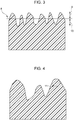
- Fig. 3 is a sectional view of irregularities in the surface of a molded product for explanation of the arithmetic mean roughness Sa.
- the arithmetic mean roughness Sa is given by Expression 1.
- the arithmetic mean roughness Sa is a parameter indicating the extension of an arithmetic mean roughness Ra evaluated on a line to a surface and is expressed in the unit ⁇ m in this case.
- Sa 1 A ⁇ A Z x y dxdy
- Z denotes a height component at x and y coordinates relative to an average level 8 (zero) of height components obtained in a measurement region having a sufficiently wide area and A denotes the area of the measurement region.
- the measurement region is 1000 ⁇ m ⁇ 1000 ⁇ m in terms of surface roughness.
- the arithmetic mean roughness Sa is the mean of absolute values of height components 9 extending from the average level 8 in a protrusion direction and absolute values of height components 10 extending from the average level 8 in a recess direction in Fig. 3 .
- the mean of height components of irregularities in the surface of a resin molded product is evaluated as a mean of the entire surface. The greater the value of the arithmetic mean roughness Sa, the greater the height components of the irregularities in the surface.
- An arithmetic mean roughness Sa less than 0.8 ⁇ m indicates that the heights of irregularities in the surface of a resin molded product are very small and the filler fibers 3 are located very close to protrusions of the irregularities.
- the filler fibers 3 in the filler-containing resin molded product 1, according to the present disclosure typically have a diameter from several micrometers to several tens of micrometers.
- the arithmetic mean roughness Sa is small, the filler tends to be visually recognized, that is, the resin molded product tends to have a poor appearance.
- an arithmetic mean roughness Sa greater than 10.0 ⁇ m indicates that irregularities are too deep. Deep irregularities may cause poor mold release when a molded product is released from a mold, causing deformation of the irregularities or whitening due to abrasion of the surface of the molded product. It may be difficult to provide a molded product having a good appearance. Furthermore, if a necessary draft angle is increased and the shape of a molded product is restricted in dimensions or if high dimensional accuracy is required because of complexity in shape, it may be difficult to meet the restriction or the dimensional accuracy requirement.
- the filler 3 is less likely to be visually recognized as the arithmetic mean roughness Sa is greater, it is difficult to permit irregularities to have a height component greater than 10.0 ⁇ m.
- the inventors have found that the height components can range from 0.8 ⁇ m to 10.0 ⁇ m.
- the inventors further have found that it is difficult to obtain the resin molded product 1 having a good appearance surface if the above-described requirement is met.
- the filler fibers 3 located in the valleys close to the surface of the molded product tend to be oriented parallel to the surface of the molded product but are not completely parallel to the surface of the molded product.
- the filler fibers 3 may be oriented in various directions due to turbulent flow of resin. In such a case, the filler fibers 3 would partly project from the surface of a molded product and be visually recognized.
- the inventors have found that the arithmetic mean curvature, Spc, of peaks of the irregularities in the surface of the molded product has to be 400 [1/mm] or greater and 900 [1/mm] or less.
- peak refers to the top of each protrusion of the ripples 5.
- the peak arithmetic mean curvature Spc represents the mean of principal curvatures of the peaks in the surface.
- Fig. 4 is a sectional view of surface irregularities for explanation of the peak arithmetic mean curvature Spc.
- the peak arithmetic mean curvature Spc is given by Expression 2.
- the peak arithmetic mean curvature Spc therefore represents the mean of reciprocals of the radii of approximate circles 11 at the peaks of the surface irregularities in Fig. 4 .
- a small peak arithmetic mean curvature Spc indicates that the ridges have a round peak having a wide width.
- a large peak arithmetic mean curvature Spc indicates that the ridges have a pointed peak having a narrow width.
- a peak arithmetic mean curvature Spc greater than 900 [1/mm] indicates that the surface irregularities include acute-angled narrow protrusions. Such a shape tends to cause diffuse reflection of light impinged on the surface of the molded product, leading to a reduction in amount of light reflected to the eyes of a person looking at the molded product.
- the glossiness of the surface of the molded product would seem to be reduced or lost. The loss of the glossiness of the surface would facilitate visual recognition of appearance defects, such as color unevenness, transfer unevenness, a resin flow mark, and filler exposed at the surface (hereinafter, referred to as "filler floating").
- the acute-angled, narrow shape of the protrusions of the surface irregularities would cause variations in resin flow conditions depending on how pressure is transmitted during molding, resulting in variations in transfer sate. Protrusions would be likely to vary in shape. This would result in a change in light reflection state in the protrusions, such that appearance unevenness of the surface of the molded product would be easily visually recognized.
- a peak arithmetic mean curvature Spc less than 400 [1/mm] indicates that the surface irregularities will cause intense reflection of light that may, in turn, result in a significant change in appearance state visually observed. It is therefore difficult to reduce the peak arithmetic mean curvature Spc to a value less than 400 [1/mm].
- arithmetic mean roughness Sa and the peak arithmetic mean curvature Spc values determined for surface texture (surface roughness measurement) in accordance with ISO 25178 published by International Organization for Standardization are used.
- the arithmetic mean roughness Sa and the peak arithmetic mean curvature Spc in this specification are values obtained by performing measurement in evaluation areas each having an area of 1000 ⁇ m ⁇ 1000 ⁇ m in a certain region with a KEYENCE VK-X160 laser microscope. Specifically, a certain region of 2 cm ⁇ 2 cm is first determined, measurement is then performed in at least 20 evaluation areas, each of which is 1000 ⁇ m ⁇ 1000 ⁇ m, in this region. The measured values are averaged.
- an arithmetic mean roughness Sa of 0.8 ⁇ m or greater and 10.0 ⁇ m or less provides a proper peak-to-valley depth on the surface of the molded product, causing the filler 3 to become difficult to see.
- a peak arithmetic mean curvature Spc of 400 [1/mm] or greater and 900 [1/mm] or less provides enhanced glossiness, causing the filler fibers slightly exposed at the surface to become more difficult to see.
- a peak arithmetic mean curvature indicates that, in transferring the shape of a mold to resin to be a molded product, valleys of irregularities of the mold to be transferred as ridges of the molded resin product have a wide, gently-sloping shape. This shape enables the resin to easily flow into the valleys, thus achieving uniform transfer and reducing or eliminating appearance unevenness due to non-uniform transfer.
- the molded product having a good appearance with no or little filler floating and no or little appearance unevenness can be provided without coating.
- the resin molded product according to the present disclosure is manufactured by injecting resin into a cavity of a mold and transferring irregularities arranged in the cavity to the resin.
- a typical molding process e.g., injection molding
- the irregularities are to be transferred to resin and provide irregularities in the resin molded product according to the present disclosure.
- a shape that provides an arithmetic mean roughness Sa of 0.8 ⁇ m or greater and 10.0 ⁇ m or less and an arithmetic mean curvature Spc of 400 [1/mm] or greater and 900 [1/mm] or less when transferred is modeled using a computer-aided design (CAD) system.
- CAD computer-aided design
- a repeated pattern is added to the shape to be modeled.
- the repeated pattern can be added under machining conditions, instead of adding the pattern during modeling using the CAD system.
- the repeated pattern can be ripples with a pitch of 60 ⁇ m or less.
- Such a pitch value provides narrow intervals between the ripples to make the appearance have uniform glossiness, thus stably providing a molded product having a good appearance with no or little filler floating and no or little appearance unevenness.
- Modeling with the CAD system enables copying of a mold cavity having the same irregularities, thus improving reproducibility and mass-productiveness.
- the modeled shape is used to generate numerical control (NC) data for machining of a workpiece into the modeled shape by using a computer-aided manufacturing (CAM) system.
- NC data is input to machining equipment, in which the surface of a mold cavity is machined.
- Fig. 5 is a diagram illustrating an exemplary configuration of a machining center, serving as an example of a machine for machining the surface of a mold cavity.
- the machining center has three axes: the axis X, the axis Y, and the axis Z.
- the machining center includes a main shaft 54, to which a tool is attached and which is rotated to allow the attached tool to cut, and a cutting tool 55.
- a workpiece 56 to be a mold is placed in the machining center.
- NC data 57 includes instructions for cutting, for example, amounts of movement along the X axis, amounts of movement along the Y axis, amounts of movement along the Z axis, the number of rotations of the main shaft 54, a moving speed along the X axis, a moving speed along the Y axis, and a moving speed along the Z axis.
- the main shaft 54 is moved and rotated based on the NC data 57 indicating the number of rotations, the moving speed along each axis, and the amounts of movement, thus allowing the cutting tool 55 to cut the workpiece 56 to be a mold.
- the cutting tool 55 attached to the main shaft 54 is moved relative to the workpiece 56 to be a mold, thus machining the workpiece into any three-dimensional shape.
- the cutting tool 55 include a ball end mill having an arc-shaped tip.
- Fig. 6 is a diagram explaining an injection molding process.
- An injection molding machine 12 is used for injection molding.
- the injection molding machine 12 includes a heater 13, a heating cylinder 14, a screw 15, and a hopper 16, which constitute an injection unit.
- the injection molding machine 12 further includes a platen (not illustrated) to which a mold 17 with a cavity having a surface machined in the above-described manner is attached. Resin pellets 18 supplied to the hopper 16 are heated and melted by the injection unit.
- the resin is injected into the mold 17 such that the mold 17 is filled with the resin, thus transferring the surface texture of the cavity of the mold to the resin.
- the resin usable may be any thermoplastic resin containing a filler.
- polycarbonate (PC) can be suitably used because it exhibits good environmental resistance, good rigidity, good strength, and good formability.
- Examples of the filler 3 usable include an inorganic filler and an organic filler.
- a glass filler can be used.
- a mixture of fillers having diameters from several micrometers to several tens of micrometers and lengths from several tens of micrometers to several hundred micrometers is often used in view of low shrinkage and low anisotropy.
- a mixture of fillers having diameters of 1 ⁇ m or greater and 90 ⁇ m or less and lengths of 10 ⁇ m or greater and 900 ⁇ m or less is often used. Any of the above-described fillers and filler mixture can be suitably used.
- the proportion of the filler to the thermoplastic resin in the filler-containing thermoplastic resin may be 5 parts by weight or greater and 40 parts by weight or less per 100 parts by weight of the thermoplastic resin.
- Fig. 7 is a schematic diagram of an exemplary resin molded product according to a second embodiment of the present disclosure and illustrates the resin molded product used as a lens barrel of an interchangeable lens for a camera.
- Fig. 8 is a sectional view of part of surface irregularities of an appearance surface of the resin molded product illustrated in Fig. 7 .
- parts having the same functions as those in Figs. 1 and 2 are designated by the same reference numerals and a detailed description of these parts is omitted.
- differences from the first embodiment will mainly be described.
- irregularities 4 have such a shape that the arithmetic mean roughness Sa is 0.8 ⁇ m or greater and 10 ⁇ m or less and a root mean square gradient Sdq is 0.3 or greater and 0.65 or less.
- This shape eliminates filler floating under conditions without coating, thus providing a resin molded product 1 having a good appearance in which the 60° glossiness defined in Japanese Industrial Standards (JIS) Z 8741 is 11 or greater and less than 60.
- an arithmetic mean roughness Sa less than 0.8 ⁇ m indicates that height components of irregularities in the surface of a molded product are very small and filler fibers 3 distributed in the vicinity of valleys 7 are located at a shallow depth relative to protrusions of the irregularities.
- the filler fibers 3 used for the resin molded product 1, according to the present disclosure typically have a diameter from several micrometers to several tens of micrometers.
- the arithmetic mean roughness Sa is small, the filler 3 tends to be visually recognized, that is, the resin molded product tends to have an appearance defect called filler floating.
- an arithmetic mean roughness Sa greater than 10.0 ⁇ m indicates that irregularities are too deep. Deep irregularities may cause poor mold release when a molded product is released from a mold, causing deformation of the irregularities or whitening due to abrasion of the surface of the molded product. It may be difficult to provide a molded product having a good appearance. Furthermore, if a draft angle necessary for a molded product is increased and the shape of the molded product is restricted in dimensions or if high dimensional accuracy is required because of complexity in shape, it may be difficult to meet the restriction or the dimensional accuracy requirement.
- the filler 3 is less likely to be visually recognized as the arithmetic mean roughness Sa is greater, it is difficult to permit irregularities to have a height component greater than 10.0 ⁇ m.
- the height components may range from 0.8 ⁇ m to 10.0 ⁇ m.
- the irregularities have such a shape that the root mean square gradient Sdq is 0.3 or greater and 0.65 or less. This shape can enhance glossiness without coating.
- the root mean square gradient Sdq of surface irregularities is designed so as to be within a proper range. Increasing or reducing fine asperities on the surface irregularities to the proper range can reduce diffuse reflection to increase the amount of light.
- the root mean square gradient Sdq which is a parameter indicating the extension of a root mean square slope Rdq on a roughness profile to a surface, is defined in ISO 25178.
- the root mean square gradient Sdq represents the mean of slopes on a surface.
- Fig. 9 is a sectional view of surface irregularities for explanation of the root mean square gradient Sdq.
- the root mean square gradient Sdq is given by Expression 3.
- Sdq 1 A ⁇ A ⁇ z x y ⁇ x 2 + ⁇ z x y ⁇ y 2 dxdy
- z denotes the height components in the x and y directions
- A denotes the area of a measurement region, which is the extension of a reference length 211 (refer to Fig. 10 ) in the x and y directions.
- Calculating the square roots of local slopes 212 in the x and y directions of the surface irregularities in Fig. 10 obtains the root mean square gradient Sdq representing the mean of slopes on a surface.
- a small root mean square gradient Sdq indicates that the surface has many gentle slopes, whereas a large root mean square gradient Sdq indicates that the
- a root mean square gradient Sdq greater than 0.65 indicates that the surface irregularities include many steep slopes. Such a shape tends to cause diffuse reflection of light impinged on the surface of a molded product, leading to a reduction in amount of light reflected to the eyes of a person looking at the molded product. The glossiness of the surface of the molded product would seem to be reduced or lost. The molded product would fail to have a 60° glossiness of 11 or greater and less than 60.
- a root mean square gradient Sdq less than 0.3 indicates that the surface irregularities significantly reflect light and the 60° glossiness is 60 or greater. Such an appearance state looks like a specular surface. This results in a significant change in appearance state visually observed. It is therefore difficult to reduce the root mean square gradient Sdq to a value less than 0.3.
- an arithmetic mean roughness Sa of 0.8 ⁇ m or greater and 10.0 ⁇ m or less provides a proper peak-to-valley depth on the surface of the molded product. This proper depth reduces a likelihood that the filler fibers 3 may be visually recognized.
- a root mean square gradient Sdq of 0.3 or greater and 0.65 or less provides a 60° glossiness of 11 or greater and less than 60, achieving necessary glossiness.
- the molded product having a good appearance with good glossiness can be provided without coating.
- the texture can satisfy both the conditions in the first embodiment and those in the second embodiment.
- the irregularities can have an arithmetic mean roughness Sa of 0.8 ⁇ m or greater and 10 ⁇ m or less, a peak arithmetic mean curvature Spc of 400 [1/mm] or greater and 900 [1/mm] or less, and a root mean square gradient Sdq of 0.3 or greater and 0.65 or less.
- a plurality of designs were created to provide irregularities having different arithmetic mean roughnesses Sa and different peak arithmetic mean curvatures Spc.
- NC data items for machining of the different designs were generated and the NC data items were input to the machining center.
- the surfaces of cavities of molds were machined using the ball end mill to form the irregularities.
- Injection molding was performed using the molds with the machined cavities such that the irregularities in each cavity were transferred to a resin material to be a molded product, thus obtaining the lens barrels of an interchangeable lens for a camera.
- the resin material used was polycarbonate (PC) (Iupilon manufactured by Mitsubishi Engineering-Plastics Corporation) containing about 30% glass filler.
- the molding machine used was J180 EL III Molding Machine (manufactured by Japan Steel Works, Ltd.). Molding conditions were set to achieve adequate transfer of the irregularities in the surfaces of the cavities of the molds.
- Irregularities of resin molded products obtained by injection molding were evaluated using the laser microscope (VK-X160 manufactured by KEYENCE CORPORATION).
- the surface texture of each of the products was measured at a magnification of 400 times, a certain region including measurement areas each having an area of 1000 ⁇ m ⁇ 1000 ⁇ m was defined in a measurement image, and the surface texture in this region was measured.
- evaluation was made based on three items, the arithmetic mean roughness Sa, the peak arithmetic mean curvature Spc, and the pitch of ripples to examine the influence of the surface irregularities on the appearance of the resin molded product.
- the appearances of the resin molded products were visually evaluated. Note that a product on which appearance unevenness, a significant change in glossiness, filler floating, and whitening were not visually recognized was determined to have a good appearance (A), a product whose appearance was not poor but fair was determined to have an acceptable appearance (B), and a product having any appearance defect was determined to be poor or unacceptable (C) .
- Table 1 lists the arithmetic mean roughnesses Sa, the peak arithmetic mean curvatures Spc, and the visually evaluated appearances of resin molded products formed using the machined cavities having irregularities designed such that the pitch of ripples was 20 ⁇ m. It was found that resin molded products of Examples 1-1 to 1-9 had a good appearance surface. This finding indicates that the surface irregularities having an arithmetic mean roughness Sa of 0.8 ⁇ m or greater and 10.0 ⁇ m or less and a peak arithmetic mean curvature Spc of 400 [1/mm] or greater and 900 [1/mm] or less provide a good appearance surface with, for example, no or little appearance unevenness and no or little filler floating.
- Resin molded products of Comparative Examples 1 to 6 had a poor appearance.
- Table 2 lists evaluated appearances of resin molded products formed using the machined cavities having irregularities designed such that the pitch of ripples was 60 ⁇ m.
- Table 3 lists evaluated appearances of resin molded products formed using cavities having irregularities designed such that the pitch of ripples was 100 ⁇ m.
- the resin molded products designed such that the pitch of ripples was 60 ⁇ m had a good appearance, which is not significantly different from that in the case where the pitch was 20 ⁇ m.
- the widened pitch increased the influence of each ripple on the appearance. Slight appearance unevenness caused by variations in glossiness in the ripples was observed.
- a plurality of designs were created to provide irregularities having different arithmetic mean roughnesses Sa and different root mean square gradients Sdq.
- NC data items for machining of the different designs were generated and the NC data items were input to the machining center.
- the surfaces of cavities of molds were machined using the ball end mill to form the irregularities.
- Injection molding was performed using the molds with the machined cavities such that the irregularities in each cavity were transferred to a resin material to be a molded product, thus obtaining the lens barrels of an interchangeable lens for a camera.
- the resin material used was polycarbonate (PC) (Iupilon manufactured by Mitsubishi Engineering-Plastics Corporation) containing about 30% glass filler.
- the molding machine used was J180 EL III Molding Machine (manufactured by Japan Steel Works, Ltd.). Molding conditions were set to achieve adequate transfer of the irregularities in the surfaces of the cavities of the molds.
- Irregularities of resin molded products obtained by injection molding were evaluated using the laser microscope (VK-X160 manufactured by KEYENCE CORPORATION).
- the surface texture of each of the products was measured at a magnification of 400 times, a certain region including evaluation areas each having an area of 1000 ⁇ m ⁇ 1000 ⁇ m was defined in a measurement image, and the surface texture in this region was measured. Specifically, evaluation was made based on three items, the arithmetic mean roughness Sa, the root mean square gradient Sdq, and the pitch of ripples to examine the influence of the surface irregularities on the appearance of the resin molded product.
- the appearances of the resin molded products were visually evaluated. Note that a product on which appearance unevenness, a significant change in glossiness, filler floating, and whitening were not visually recognized was determined to have a good appearance (A), a product whose appearance was not poor but fair was determined to have an acceptable appearance (B), and a product having any appearance defect was determined to be poor or unacceptable (C) .
- Table 4 lists the arithmetic mean roughnesses Sa, the root mean square gradients Sdq of resin molded products obtained using the machined cavities having irregularities designed such that the pitch of ripples was 20 ⁇ m. Table 4 further illustrates visual evaluation results of filler floating, glossiness, and other appearance defects of the resin molded products. It was found that the resin molded products of Examples 4-1 to 4-9 had a good appearance surface with no or little filler floating and with good glossiness. This finding indicates that the surface irregularities having an arithmetic mean roughness Sa of 0.8 ⁇ m or greater and 10.0 ⁇ m or less and a root mean square gradient Sdq of 0.3 or greater and 0.65 or less provide a good appearance surface with necessary glossiness and with no or little filler floating.
- the resin molded products of Comparative Examples 5 to 9 had a poor appearance.
- Comparative Examples 7 and 8 the irregularities were too deep. Poor mold release and deformation of the irregularities were observed. If a necessary draft angle is increased and the shape of a molded product is restricted in dimensions or if high dimensional accuracy is required because of complexity in shape, it may be difficult to meet the restriction or the dimensional accuracy requirement. In view of these circumstances, the products of Comparative Examples 7 and 8 were determined to be unacceptable.
- Table 5 lists arithmetic mean roughnesses Sa and root mean square gradients Sdq of resin molded products obtained using the machined cavities having irregularities designed such that the pitch of ripples was 60 ⁇ m.
- Table 6 lists arithmetic mean roughnesses Sa and root mean square gradients Sdq of resin molded products obtained using the machined cavities having irregularities designed such that the pitch of ripples was 100 ⁇ m.
- Tables 5 and 6 further illustrate visual evaluation results of filler floating, glossiness, and other appearance defects of the resin molded products. The resin molded products designed such that the pitch of ripples was 60 ⁇ m had a good appearance, which is not significantly different from that in the case where the pitch was 20 ⁇ m.
- iridescent appearance refers to an appearance defect indicating that the surface of a molded product seems to have an iridescent surface depending on, for example, differences in optical path length caused by irregularities of the molded product or a light reflected state, that is, the ratio of regular reflection to irregular reflection (diffuse reflection).
- a plurality of designs were created to provide irregularities having different arithmetic mean roughnesses Sa, different peak arithmetic mean curvatures Spc, and different root mean square gradients Sdq.
- NC data items for machining of the different designs were generated and the NC data items were input to the machining center.
- the surfaces of cavities of molds were machined using the ball end mill to form the irregularities.
- Injection molding was performed using the molds with the machined cavities such that the irregularities in each cavity were transferred to a resin material to be a molded product, thus obtaining the lens barrels of an interchangeable lens for a camera.
- the resin material used was polycarbonate (PC) (Iupilon manufactured by Mitsubishi Engineering-Plastics Corporation) containing about 30% glass filler.
- the molding machine used was J180 EL III Molding Machine (manufactured by Japan Steel Works, Ltd.). Molding conditions were set to achieve adequate transfer of the irregularities in the surfaces of the cavities of the molds.
- Irregularities of resin molded products obtained by injection molding were evaluated using the laser microscope (VK-X160 manufactured by KEYENCE CORPORATION).
- the surface texture of each of the products was measured at a magnification of 400 times, a certain region including evaluation areas each having an area of 1000 ⁇ m ⁇ 1000 ⁇ m was defined in a measurement image, and the surface texture in this region was measured. Specifically, evaluation was made based on the arithmetic mean roughness Sa, the peak arithmetic mean curvature Spc, and the root mean square gradient Sdq to examine the influence of the surface irregularities on the appearance of the resin molded product.
- the appearances of the resin molded products were visually evaluated with respect to iridescent appearance and other appearance defects including filler floating and appearance unevenness. Note that a product on which any appearance defects were not visually recognized was determined to have a good appearance (A), a product whose appearance was not poor but fair was determined to have an acceptable appearance (B), and a product on which any appearance defect was visually recognized was determined to be poor or unacceptable (C).
- Tables 7 and 8 list the evaluation results of the appearances of the molded products having the irregularities with the different peak arithmetic mean curvatures Spc, the different root mean square gradients Sdq, and the different arithmetic mean roughnesses Sa that lie in a range where filler floating does not tend to occur, as demonstrated in Examples 1 and 2, and that lie in a lower limit range from 0.8 to 1.2 ⁇ m where diffuse reflection does not tend to occur and an iridescent pattern can be easily visually recognized.
- the resin molded products of Examples 7-1 to 7-3 had a good appearance in which any appearance defect was not visually recognized.
- the resin molded product of Example 7-4 was slightly inferior only in iridescent appearance to the products of Examples 7-1 to 7-3 but the degree of the iridescent appearance did not reach a defective level.
- the resin molded products of Examples 8-1 to 8-3 had a good appearance in which any appearance defect was not visually recognized.
- the resin molded product of Example 8-4 was slightly inferior only in iridescent appearance to the products of Examples 8-1 to 8-3 but the degree of the iridescent appearance did not reach a defective level.
- Comparative Example 10 the peak arithmetic mean curvature Spc was less than 380 [1/mm]. In Comparative Example 11, the root mean square gradient Sdq was less than 0.3. These resin molded products hardly caused diffuse reflection. Consequently, the amount of light reflected to the eyes of a person viewing these resin molded products was increased. It is conceivable that the visually observed appearances of the molded products significantly changed and their iridescent patterns were clearly seen and visually recognized as appearance defects.
- Sa arithmetic mean roughness
- Spc peak arithmetic mean curvature
Landscapes
- Engineering & Computer Science (AREA)
- Manufacturing & Machinery (AREA)
- Mechanical Engineering (AREA)
- Physics & Mathematics (AREA)
- Health & Medical Sciences (AREA)
- Ophthalmology & Optometry (AREA)
- General Physics & Mathematics (AREA)
- Optics & Photonics (AREA)
- Chemical & Material Sciences (AREA)
- Dispersion Chemistry (AREA)
- Microelectronics & Electronic Packaging (AREA)
- Moulds For Moulding Plastics Or The Like (AREA)
Claims (11)
- Harzformprodukt (1) mit:einer Oberfläche (2), die unter Verwendung eines thermoplastischen Harzes ausgebildet ist,wobei Unregelmäßigkeiten (4) von einem Formhohlraum auf die Oberfläche übertragen sind und eine mittlere arithmetische Rauheit (Sa) von 0,8 µm oder mehr und 10 µm oder weniger und einen arithmetischen Mittelwert der Spitzenkrümmung (Spc) von 400 [1/mm] oder mehr und 900 [1/mm] oder weniger haben.
- Harzformprodukt (1) mit:einer Oberfläche (2), die unter Verwendung von Harz ausgebildet ist,wobei Unregelmäßigkeiten (4) von einem Formhohlraum auf die Oberfläche übertragen sind und eine mittlere arithmetische Rauheit (Sa) von 0,8 µm oder mehr und 10 µm oder weniger und einen quadratischen Neigungsmittelwert (Sdq) von 0,3 oder mehr und 0,65 oder weniger haben.
- Harzformprodukt (1) mit:einer Oberfläche (2), die unter Verwendung von Harz ausgebildet ist,wobei Unregelmäßigkeiten (4) von einem Formhohlraum auf die Oberfläche übertragen sind und eine mittlere arithmetische Rauheit (Sa) von 0,8 µm oder mehr und 10 µm oder weniger, einen arithmetischen Mittelwert der Spitzenkrümmung (Spc) von 400 [1/mm] oder mehr und 900 [1/mm] oder weniger und einen quadratischen Neigungsmittelwert (Sdq) von 0,3 oder mehr und 0,65 oder weniger haben.
- Harzformprodukt nach einem der Ansprüche 1 bis 3, wobei der arithmetische Mittelwert der Spitzenkrümmung 450 [1/mm] oder mehr und 900 [1/mm] oder weniger beträgt.
- Harzformprodukt nach Anspruch 2 oder 3, wobei der quadratische Neigungsmittelwert 0,4 oder mehr und 0,65 oder weniger beträgt.
- Harzformprodukt nach einem der Ansprüche 1 bis 5, wobei die Unregelmäßigkeiten ein wiederholtes Muster umfassen.
- Harzformprodukt nach einem der Ansprüche 1 bis 6, wobei die Unregelmäßigkeiten Wellen (5) mit einem Abstand von 60 µm oder weniger umfassen.
- Harzformprodukt nach einem der Ansprüche 1 bis 7, wobei das Harz einen anorganischen oder organischen Füllstoff (3) enthält.
- Harzformprodukt nach einem der Ansprüche 1 bis 8, wobei das Harz einen Füllstoff (3) enthält, der einen Durchmesser von 1 µm oder mehr und 90 µm oder weniger und eine Länge von 10 µm oder mehr und 900 µm oder weniger hat.
- Wechselobjektiv für eine Kamera, wobei das Objektiv Folgendes umfasst:
das Harzformprodukt gemäß einem der Ansprüche 1 bis 9. - Verfahren zur Herstellung des Harzformprodukts (1) gemäß einem der Ansprüche 1 bis 9, wobei das Verfahren Folgendes umfasst:Ausbilden von Unregelmäßigkeiten auf einer Oberfläche eines Formhohlraums; undEinspritzen von Harz in den Formhohlraum, wodurch die auf der Oberfläche des Formhohlraums ausgebildeten Unregelmäßigkeiten auf die Oberfläche (2) des Harzformprodukts (1) übertragen werden.
Applications Claiming Priority (2)
| Application Number | Priority Date | Filing Date | Title |
|---|---|---|---|
| JP2016098988 | 2016-05-17 | ||
| JP2017079189A JP6494683B2 (ja) | 2016-05-17 | 2017-04-12 | 樹脂成形品、カメラ用交換レンズおよび樹脂成形品の製造方法 |
Publications (2)
| Publication Number | Publication Date |
|---|---|
| EP3246147A1 EP3246147A1 (de) | 2017-11-22 |
| EP3246147B1 true EP3246147B1 (de) | 2019-07-10 |
Family
ID=58671416
Family Applications (1)
| Application Number | Title | Priority Date | Filing Date |
|---|---|---|---|
| EP17168943.3A Active EP3246147B1 (de) | 2016-05-17 | 2017-05-02 | Harzgeformtes produkt, wechselobjektiv für kamera und verfahren zur herstellung des harzgeformten produkts |
Country Status (3)
| Country | Link |
|---|---|
| US (1) | US10495788B2 (de) |
| EP (1) | EP3246147B1 (de) |
| CN (1) | CN107379586B (de) |
Families Citing this family (9)
| Publication number | Priority date | Publication date | Assignee | Title |
|---|---|---|---|---|
| JP7179438B2 (ja) * | 2016-08-25 | 2022-11-29 | キヤノン株式会社 | 金型の製造方法及び樹脂成形品の製造方法 |
| KR102393826B1 (ko) | 2018-04-27 | 2022-05-03 | 제이엑스금속주식회사 | 표면 처리 구리박, 동장 적층판 및 프린트 배선판 |
| CN112368826A (zh) | 2018-06-22 | 2021-02-12 | 积水保力马科技株式会社 | 热传导性片 |
| US11762306B2 (en) | 2018-09-05 | 2023-09-19 | Nok Corporation | Electroconductive roll |
| CN112715059B (zh) * | 2018-09-26 | 2024-09-06 | 积水保力马科技株式会社 | 导热片 |
| EP3628758A1 (de) | 2018-09-27 | 2020-04-01 | Apple Inc. | Strukturierte oberfläche für titanteile |
| JP7490427B2 (ja) | 2020-04-07 | 2024-05-27 | キヤノン株式会社 | 樹脂成形品、樹脂成形品の製造方法、金型、樹脂成形品の製造装置、カメラ、プリンター |
| US11459668B2 (en) | 2020-05-06 | 2022-10-04 | Apple, Inc. | Titanium part having an anodized layer |
| JP7303276B2 (ja) * | 2021-06-16 | 2023-07-04 | 長春石油化學股▲分▼有限公司 | エチレン-ビニルアルコール共重合体樹脂組成物 |
Family Cites Families (9)
| Publication number | Priority date | Publication date | Assignee | Title |
|---|---|---|---|---|
| JP3630950B2 (ja) | 1997-10-24 | 2005-03-23 | キヤノン株式会社 | 球面レンズの製造方法 |
| US6024448A (en) | 1998-03-31 | 2000-02-15 | Johnson & Johnson Vision Products, Inc. | Contact lenses bearing identifying marks |
| JP4667557B2 (ja) | 2000-05-17 | 2011-04-13 | オリンパス株式会社 | 繊維強化熱可塑性樹脂成形品の製造方法 |
| JP2003014938A (ja) | 2001-04-12 | 2003-01-15 | Mitsubishi Engineering Plastics Corp | 透明樹脂製の導光板及びその成形方法、入れ子、金型組立体、並びに、面状光源装置 |
| JP2004347621A (ja) | 2003-04-24 | 2004-12-09 | Dainippon Printing Co Ltd | 透過型スクリーン |
| JP4356395B2 (ja) | 2003-08-21 | 2009-11-04 | 住友ベークライト株式会社 | プラスチック複合透明シート及びそれを使用した表示素子 |
| US9067045B2 (en) | 2008-07-25 | 2015-06-30 | Cook Medical Technologies Llc | Balloon catheter and method for making same |
| CN102362247B (zh) | 2009-03-27 | 2015-08-12 | 木本股份有限公司 | 防牛顿环片材和使用了其的触摸屏 |
| FR2982785B1 (fr) | 2011-11-22 | 2013-12-20 | Essilor Int | Procede d'obtention d'une lentille ophtalmique |
-
2017
- 2017-05-01 US US15/583,218 patent/US10495788B2/en active Active
- 2017-05-02 EP EP17168943.3A patent/EP3246147B1/de active Active
- 2017-05-17 CN CN201710345459.9A patent/CN107379586B/zh active Active
Non-Patent Citations (1)
| Title |
|---|
| None * |
Also Published As
| Publication number | Publication date |
|---|---|
| CN107379586B (zh) | 2020-07-28 |
| US10495788B2 (en) | 2019-12-03 |
| CN107379586A (zh) | 2017-11-24 |
| EP3246147A1 (de) | 2017-11-22 |
| US20170336535A1 (en) | 2017-11-23 |
Similar Documents
| Publication | Publication Date | Title |
|---|---|---|
| EP3246147A1 (de) | Harzgeformtes produkt, wechselobjektiv für kamera und verfahren zur herstellung des harzgeformten produkts | |
| Alsoufi et al. | Surface roughness quality and dimensional accuracy—a comprehensive analysis of 100% infill printed parts fabricated by a personal/desktop cost-effective FDM 3D printer | |
| JP6560982B2 (ja) | 眼用レンズ上に恒久的技術マークを生成するためのマーキングステップを含む眼用レンズ製造方法 | |
| Ishida et al. | Dimensional accuracy of dental casting patterns created by 3D printers | |
| CN105283301B (zh) | 用于制造眼镜片的方法和机器 | |
| Kovan et al. | Printing parameters effect on surface characteristics of 3D printed PLA materials | |
| DE102009004377C5 (de) | Verfahren zum Herstellen eines Brillenglases, Computerprogrammprodukt, Verwendung und Brillenglasherstellungsgerät | |
| US20170008792A1 (en) | Glass manufacturing mold | |
| KR20160015263A (ko) | 안과용 렌즈를 제조하기 위한 공정 및 시스템 | |
| CN111819061B (zh) | 产品和制造产品的方法 | |
| US20230391003A1 (en) | Contour Smoothing for Material Extrusion Three-Dimensionally Printed Parts | |
| EP3760423A1 (de) | Verfahren zur herstellung optischer linsen unter verwendung von 3d-gedruckten funktionalen wafern | |
| JP6494683B2 (ja) | 樹脂成形品、カメラ用交換レンズおよび樹脂成形品の製造方法 | |
| Vesco et al. | Fuzzy skin in fused filament fabrication: Enhancing morphology, wettability, and friction through a full-factorial experimental plan | |
| JP7292974B2 (ja) | 樹脂製物品、電子機器、および樹脂製物品の製造方法 | |
| Li et al. | An affordable injection-molded precision hybrid glass–polymer achromatic lens | |
| CN106794603A (zh) | 树脂成型用模具 | |
| CN111751913B (zh) | 外部构件、照相机、可更换镜头、打印机、以及外部构件的制造方法 | |
| Singh et al. | Experimental investigations for statistically controlled rapid moulding solution of plastics using polyjet printing | |
| CN101378878B (zh) | 制造用于制造隐形眼镜的半模的方法 | |
| EP2064043B1 (de) | Spritzgegossenes produkt | |
| JP2002128909A (ja) | 樹脂製窓製品 | |
| US20100021724A1 (en) | Injection molded product | |
| CN115485123A (zh) | 增材制造用于灯具的透明透镜的方法 | |
| Atzeni et al. | Dimensional analysis of a prototype mould-making process for thermoplastic resin transfer moulding |
Legal Events
| Date | Code | Title | Description |
|---|---|---|---|
| PUAI | Public reference made under article 153(3) epc to a published international application that has entered the european phase |
Free format text: ORIGINAL CODE: 0009012 |
|
| STAA | Information on the status of an ep patent application or granted ep patent |
Free format text: STATUS: THE APPLICATION HAS BEEN PUBLISHED |
|
| AK | Designated contracting states |
Kind code of ref document: A1 Designated state(s): AL AT BE BG CH CY CZ DE DK EE ES FI FR GB GR HR HU IE IS IT LI LT LU LV MC MK MT NL NO PL PT RO RS SE SI SK SM TR |
|
| AX | Request for extension of the european patent |
Extension state: BA ME |
|
| STAA | Information on the status of an ep patent application or granted ep patent |
Free format text: STATUS: REQUEST FOR EXAMINATION WAS MADE |
|
| 17P | Request for examination filed |
Effective date: 20180522 |
|
| RBV | Designated contracting states (corrected) |
Designated state(s): AL AT BE BG CH CY CZ DE DK EE ES FI FR GB GR HR HU IE IS IT LI LT LU LV MC MK MT NL NO PL PT RO RS SE SI SK SM TR |
|
| RIC1 | Information provided on ipc code assigned before grant |
Ipc: B29K 105/12 20060101ALN20181002BHEP Ipc: B29K 69/00 20060101ALI20181002BHEP Ipc: B29C 45/37 20060101AFI20181002BHEP Ipc: B29C 45/00 20060101ALI20181002BHEP Ipc: G02B 1/04 20060101ALI20181002BHEP Ipc: G02B 7/14 20060101ALI20181002BHEP Ipc: B29D 11/00 20060101ALI20181002BHEP Ipc: B29K 509/08 20060101ALN20181002BHEP Ipc: B29K 105/16 20060101ALN20181002BHEP |
|
| GRAP | Despatch of communication of intention to grant a patent |
Free format text: ORIGINAL CODE: EPIDOSNIGR1 |
|
| STAA | Information on the status of an ep patent application or granted ep patent |
Free format text: STATUS: GRANT OF PATENT IS INTENDED |
|
| INTG | Intention to grant announced |
Effective date: 20181121 |
|
| GRAS | Grant fee paid |
Free format text: ORIGINAL CODE: EPIDOSNIGR3 |
|
| GRAA | (expected) grant |
Free format text: ORIGINAL CODE: 0009210 |
|
| STAA | Information on the status of an ep patent application or granted ep patent |
Free format text: STATUS: THE PATENT HAS BEEN GRANTED |
|
| AK | Designated contracting states |
Kind code of ref document: B1 Designated state(s): AL AT BE BG CH CY CZ DE DK EE ES FI FR GB GR HR HU IE IS IT LI LT LU LV MC MK MT NL NO PL PT RO RS SE SI SK SM TR |
|
| REG | Reference to a national code |
Ref country code: GB Ref legal event code: FG4D |
|
| REG | Reference to a national code |
Ref country code: CH Ref legal event code: EP Ref country code: AT Ref legal event code: REF Ref document number: 1153062 Country of ref document: AT Kind code of ref document: T Effective date: 20190715 |
|
| REG | Reference to a national code |
Ref country code: DE Ref legal event code: R096 Ref document number: 602017005109 Country of ref document: DE |
|
| REG | Reference to a national code |
Ref country code: IE Ref legal event code: FG4D |
|
| REG | Reference to a national code |
Ref country code: NL Ref legal event code: MP Effective date: 20190710 |
|
| REG | Reference to a national code |
Ref country code: LT Ref legal event code: MG4D |
|
| REG | Reference to a national code |
Ref country code: AT Ref legal event code: MK05 Ref document number: 1153062 Country of ref document: AT Kind code of ref document: T Effective date: 20190710 |
|
| PG25 | Lapsed in a contracting state [announced via postgrant information from national office to epo] |
Ref country code: LT Free format text: LAPSE BECAUSE OF FAILURE TO SUBMIT A TRANSLATION OF THE DESCRIPTION OR TO PAY THE FEE WITHIN THE PRESCRIBED TIME-LIMIT Effective date: 20190710 Ref country code: PT Free format text: LAPSE BECAUSE OF FAILURE TO SUBMIT A TRANSLATION OF THE DESCRIPTION OR TO PAY THE FEE WITHIN THE PRESCRIBED TIME-LIMIT Effective date: 20191111 Ref country code: FI Free format text: LAPSE BECAUSE OF FAILURE TO SUBMIT A TRANSLATION OF THE DESCRIPTION OR TO PAY THE FEE WITHIN THE PRESCRIBED TIME-LIMIT Effective date: 20190710 Ref country code: NL Free format text: LAPSE BECAUSE OF FAILURE TO SUBMIT A TRANSLATION OF THE DESCRIPTION OR TO PAY THE FEE WITHIN THE PRESCRIBED TIME-LIMIT Effective date: 20190710 Ref country code: NO Free format text: LAPSE BECAUSE OF FAILURE TO SUBMIT A TRANSLATION OF THE DESCRIPTION OR TO PAY THE FEE WITHIN THE PRESCRIBED TIME-LIMIT Effective date: 20191010 Ref country code: BG Free format text: LAPSE BECAUSE OF FAILURE TO SUBMIT A TRANSLATION OF THE DESCRIPTION OR TO PAY THE FEE WITHIN THE PRESCRIBED TIME-LIMIT Effective date: 20191010 Ref country code: AT Free format text: LAPSE BECAUSE OF FAILURE TO SUBMIT A TRANSLATION OF THE DESCRIPTION OR TO PAY THE FEE WITHIN THE PRESCRIBED TIME-LIMIT Effective date: 20190710 Ref country code: SE Free format text: LAPSE BECAUSE OF FAILURE TO SUBMIT A TRANSLATION OF THE DESCRIPTION OR TO PAY THE FEE WITHIN THE PRESCRIBED TIME-LIMIT Effective date: 20190710 Ref country code: HR Free format text: LAPSE BECAUSE OF FAILURE TO SUBMIT A TRANSLATION OF THE DESCRIPTION OR TO PAY THE FEE WITHIN THE PRESCRIBED TIME-LIMIT Effective date: 20190710 |
|
| PG25 | Lapsed in a contracting state [announced via postgrant information from national office to epo] |
Ref country code: IS Free format text: LAPSE BECAUSE OF FAILURE TO SUBMIT A TRANSLATION OF THE DESCRIPTION OR TO PAY THE FEE WITHIN THE PRESCRIBED TIME-LIMIT Effective date: 20191110 Ref country code: GR Free format text: LAPSE BECAUSE OF FAILURE TO SUBMIT A TRANSLATION OF THE DESCRIPTION OR TO PAY THE FEE WITHIN THE PRESCRIBED TIME-LIMIT Effective date: 20191011 Ref country code: LV Free format text: LAPSE BECAUSE OF FAILURE TO SUBMIT A TRANSLATION OF THE DESCRIPTION OR TO PAY THE FEE WITHIN THE PRESCRIBED TIME-LIMIT Effective date: 20190710 Ref country code: RS Free format text: LAPSE BECAUSE OF FAILURE TO SUBMIT A TRANSLATION OF THE DESCRIPTION OR TO PAY THE FEE WITHIN THE PRESCRIBED TIME-LIMIT Effective date: 20190710 Ref country code: AL Free format text: LAPSE BECAUSE OF FAILURE TO SUBMIT A TRANSLATION OF THE DESCRIPTION OR TO PAY THE FEE WITHIN THE PRESCRIBED TIME-LIMIT Effective date: 20190710 Ref country code: ES Free format text: LAPSE BECAUSE OF FAILURE TO SUBMIT A TRANSLATION OF THE DESCRIPTION OR TO PAY THE FEE WITHIN THE PRESCRIBED TIME-LIMIT Effective date: 20190710 |
|
| PG25 | Lapsed in a contracting state [announced via postgrant information from national office to epo] |
Ref country code: TR Free format text: LAPSE BECAUSE OF FAILURE TO SUBMIT A TRANSLATION OF THE DESCRIPTION OR TO PAY THE FEE WITHIN THE PRESCRIBED TIME-LIMIT Effective date: 20190710 |
|
| PG25 | Lapsed in a contracting state [announced via postgrant information from national office to epo] |
Ref country code: DK Free format text: LAPSE BECAUSE OF FAILURE TO SUBMIT A TRANSLATION OF THE DESCRIPTION OR TO PAY THE FEE WITHIN THE PRESCRIBED TIME-LIMIT Effective date: 20190710 Ref country code: EE Free format text: LAPSE BECAUSE OF FAILURE TO SUBMIT A TRANSLATION OF THE DESCRIPTION OR TO PAY THE FEE WITHIN THE PRESCRIBED TIME-LIMIT Effective date: 20190710 Ref country code: PL Free format text: LAPSE BECAUSE OF FAILURE TO SUBMIT A TRANSLATION OF THE DESCRIPTION OR TO PAY THE FEE WITHIN THE PRESCRIBED TIME-LIMIT Effective date: 20190710 Ref country code: IT Free format text: LAPSE BECAUSE OF FAILURE TO SUBMIT A TRANSLATION OF THE DESCRIPTION OR TO PAY THE FEE WITHIN THE PRESCRIBED TIME-LIMIT Effective date: 20190710 Ref country code: RO Free format text: LAPSE BECAUSE OF FAILURE TO SUBMIT A TRANSLATION OF THE DESCRIPTION OR TO PAY THE FEE WITHIN THE PRESCRIBED TIME-LIMIT Effective date: 20190710 |
|
| PG25 | Lapsed in a contracting state [announced via postgrant information from national office to epo] |
Ref country code: SM Free format text: LAPSE BECAUSE OF FAILURE TO SUBMIT A TRANSLATION OF THE DESCRIPTION OR TO PAY THE FEE WITHIN THE PRESCRIBED TIME-LIMIT Effective date: 20190710 Ref country code: CZ Free format text: LAPSE BECAUSE OF FAILURE TO SUBMIT A TRANSLATION OF THE DESCRIPTION OR TO PAY THE FEE WITHIN THE PRESCRIBED TIME-LIMIT Effective date: 20190710 Ref country code: SK Free format text: LAPSE BECAUSE OF FAILURE TO SUBMIT A TRANSLATION OF THE DESCRIPTION OR TO PAY THE FEE WITHIN THE PRESCRIBED TIME-LIMIT Effective date: 20190710 Ref country code: IS Free format text: LAPSE BECAUSE OF FAILURE TO SUBMIT A TRANSLATION OF THE DESCRIPTION OR TO PAY THE FEE WITHIN THE PRESCRIBED TIME-LIMIT Effective date: 20200224 |
|
| REG | Reference to a national code |
Ref country code: DE Ref legal event code: R097 Ref document number: 602017005109 Country of ref document: DE |
|
| PLBE | No opposition filed within time limit |
Free format text: ORIGINAL CODE: 0009261 |
|
| STAA | Information on the status of an ep patent application or granted ep patent |
Free format text: STATUS: NO OPPOSITION FILED WITHIN TIME LIMIT |
|
| PG2D | Information on lapse in contracting state deleted |
Ref country code: IS |
|
| 26N | No opposition filed |
Effective date: 20200603 |
|
| PG25 | Lapsed in a contracting state [announced via postgrant information from national office to epo] |
Ref country code: SI Free format text: LAPSE BECAUSE OF FAILURE TO SUBMIT A TRANSLATION OF THE DESCRIPTION OR TO PAY THE FEE WITHIN THE PRESCRIBED TIME-LIMIT Effective date: 20190710 |
|
| PG25 | Lapsed in a contracting state [announced via postgrant information from national office to epo] |
Ref country code: MC Free format text: LAPSE BECAUSE OF FAILURE TO SUBMIT A TRANSLATION OF THE DESCRIPTION OR TO PAY THE FEE WITHIN THE PRESCRIBED TIME-LIMIT Effective date: 20190710 Ref country code: CH Free format text: LAPSE BECAUSE OF NON-PAYMENT OF DUE FEES Effective date: 20200531 Ref country code: LI Free format text: LAPSE BECAUSE OF NON-PAYMENT OF DUE FEES Effective date: 20200531 |
|
| REG | Reference to a national code |
Ref country code: BE Ref legal event code: MM Effective date: 20200531 |
|
| PG25 | Lapsed in a contracting state [announced via postgrant information from national office to epo] |
Ref country code: LU Free format text: LAPSE BECAUSE OF NON-PAYMENT OF DUE FEES Effective date: 20200502 |
|
| PG25 | Lapsed in a contracting state [announced via postgrant information from national office to epo] |
Ref country code: IE Free format text: LAPSE BECAUSE OF NON-PAYMENT OF DUE FEES Effective date: 20200502 Ref country code: FR Free format text: LAPSE BECAUSE OF NON-PAYMENT OF DUE FEES Effective date: 20200531 |
|
| PG25 | Lapsed in a contracting state [announced via postgrant information from national office to epo] |
Ref country code: BE Free format text: LAPSE BECAUSE OF NON-PAYMENT OF DUE FEES Effective date: 20200531 |
|
| GBPC | Gb: european patent ceased through non-payment of renewal fee |
Effective date: 20210502 |
|
| PG25 | Lapsed in a contracting state [announced via postgrant information from national office to epo] |
Ref country code: GB Free format text: LAPSE BECAUSE OF NON-PAYMENT OF DUE FEES Effective date: 20210502 |
|
| PG25 | Lapsed in a contracting state [announced via postgrant information from national office to epo] |
Ref country code: MT Free format text: LAPSE BECAUSE OF FAILURE TO SUBMIT A TRANSLATION OF THE DESCRIPTION OR TO PAY THE FEE WITHIN THE PRESCRIBED TIME-LIMIT Effective date: 20190710 Ref country code: CY Free format text: LAPSE BECAUSE OF FAILURE TO SUBMIT A TRANSLATION OF THE DESCRIPTION OR TO PAY THE FEE WITHIN THE PRESCRIBED TIME-LIMIT Effective date: 20190710 |
|
| PG25 | Lapsed in a contracting state [announced via postgrant information from national office to epo] |
Ref country code: MK Free format text: LAPSE BECAUSE OF FAILURE TO SUBMIT A TRANSLATION OF THE DESCRIPTION OR TO PAY THE FEE WITHIN THE PRESCRIBED TIME-LIMIT Effective date: 20190710 |
|
| PGFP | Annual fee paid to national office [announced via postgrant information from national office to epo] |
Ref country code: DE Payment date: 20250423 Year of fee payment: 9 |