EP3244065B1 - Variable displacement type compressor and refrigeration device having same - Google Patents
Variable displacement type compressor and refrigeration device having same Download PDFInfo
- Publication number
- EP3244065B1 EP3244065B1 EP16840326.9A EP16840326A EP3244065B1 EP 3244065 B1 EP3244065 B1 EP 3244065B1 EP 16840326 A EP16840326 A EP 16840326A EP 3244065 B1 EP3244065 B1 EP 3244065B1
- Authority
- EP
- European Patent Office
- Prior art keywords
- variable
- capacity
- cylinder
- valve
- pressure
- Prior art date
- Legal status (The legal status is an assumption and is not a legal conclusion. Google has not performed a legal analysis and makes no representation as to the accuracy of the status listed.)
- Active
Links
- 238000005057 refrigeration Methods 0.000 title claims description 48
- 238000006073 displacement reaction Methods 0.000 title claims description 8
- 230000006835 compression Effects 0.000 claims description 137
- 238000007906 compression Methods 0.000 claims description 137
- 238000004891 communication Methods 0.000 claims description 90
- 230000007246 mechanism Effects 0.000 claims description 30
- 238000002955 isolation Methods 0.000 claims description 28
- 238000005192 partition Methods 0.000 claims description 25
- 239000000696 magnetic material Substances 0.000 claims description 9
- 239000007789 gas Substances 0.000 description 63
- 239000003507 refrigerant Substances 0.000 description 48
- 230000009471 action Effects 0.000 description 19
- 230000005484 gravity Effects 0.000 description 15
- 238000010438 heat treatment Methods 0.000 description 13
- 239000007788 liquid Substances 0.000 description 13
- 230000036961 partial effect Effects 0.000 description 13
- 230000006698 induction Effects 0.000 description 8
- 238000007789 sealing Methods 0.000 description 6
- 230000000694 effects Effects 0.000 description 5
- 238000005461 lubrication Methods 0.000 description 3
- 230000002829 reductive effect Effects 0.000 description 3
- 238000013461 design Methods 0.000 description 2
- 238000009434 installation Methods 0.000 description 2
- 239000000463 material Substances 0.000 description 2
- 230000002411 adverse Effects 0.000 description 1
- 230000006866 deterioration Effects 0.000 description 1
- 238000007599 discharging Methods 0.000 description 1
- 238000005265 energy consumption Methods 0.000 description 1
- 239000012530 fluid Substances 0.000 description 1
- 230000002401 inhibitory effect Effects 0.000 description 1
- 230000003993 interaction Effects 0.000 description 1
- 230000000670 limiting effect Effects 0.000 description 1
- 230000001050 lubricating effect Effects 0.000 description 1
- 238000003754 machining Methods 0.000 description 1
- 238000004519 manufacturing process Methods 0.000 description 1
- 238000000034 method Methods 0.000 description 1
- 238000012986 modification Methods 0.000 description 1
- 230000004048 modification Effects 0.000 description 1
- 230000000149 penetrating effect Effects 0.000 description 1
- 230000008569 process Effects 0.000 description 1
- 238000012545 processing Methods 0.000 description 1
- 238000000926 separation method Methods 0.000 description 1
- 238000012546 transfer Methods 0.000 description 1
Images


Classifications
-
- F—MECHANICAL ENGINEERING; LIGHTING; HEATING; WEAPONS; BLASTING
- F04—POSITIVE - DISPLACEMENT MACHINES FOR LIQUIDS; PUMPS FOR LIQUIDS OR ELASTIC FLUIDS
- F04C—ROTARY-PISTON, OR OSCILLATING-PISTON, POSITIVE-DISPLACEMENT MACHINES FOR LIQUIDS; ROTARY-PISTON, OR OSCILLATING-PISTON, POSITIVE-DISPLACEMENT PUMPS
- F04C28/00—Control of, monitoring of, or safety arrangements for, pumps or pumping installations specially adapted for elastic fluids
- F04C28/10—Control of, monitoring of, or safety arrangements for, pumps or pumping installations specially adapted for elastic fluids characterised by changing the positions of the inlet or outlet openings with respect to the working chamber
- F04C28/12—Control of, monitoring of, or safety arrangements for, pumps or pumping installations specially adapted for elastic fluids characterised by changing the positions of the inlet or outlet openings with respect to the working chamber using sliding valves
-
- F—MECHANICAL ENGINEERING; LIGHTING; HEATING; WEAPONS; BLASTING
- F04—POSITIVE - DISPLACEMENT MACHINES FOR LIQUIDS; PUMPS FOR LIQUIDS OR ELASTIC FLUIDS
- F04C—ROTARY-PISTON, OR OSCILLATING-PISTON, POSITIVE-DISPLACEMENT MACHINES FOR LIQUIDS; ROTARY-PISTON, OR OSCILLATING-PISTON, POSITIVE-DISPLACEMENT PUMPS
- F04C23/00—Combinations of two or more pumps, each being of rotary-piston or oscillating-piston type, specially adapted for elastic fluids; Pumping installations specially adapted for elastic fluids; Multi-stage pumps specially adapted for elastic fluids
- F04C23/001—Combinations of two or more pumps, each being of rotary-piston or oscillating-piston type, specially adapted for elastic fluids; Pumping installations specially adapted for elastic fluids; Multi-stage pumps specially adapted for elastic fluids of similar working principle
-
- F—MECHANICAL ENGINEERING; LIGHTING; HEATING; WEAPONS; BLASTING
- F04—POSITIVE - DISPLACEMENT MACHINES FOR LIQUIDS; PUMPS FOR LIQUIDS OR ELASTIC FLUIDS
- F04C—ROTARY-PISTON, OR OSCILLATING-PISTON, POSITIVE-DISPLACEMENT MACHINES FOR LIQUIDS; ROTARY-PISTON, OR OSCILLATING-PISTON, POSITIVE-DISPLACEMENT PUMPS
- F04C18/00—Rotary-piston pumps specially adapted for elastic fluids
- F04C18/30—Rotary-piston pumps specially adapted for elastic fluids having the characteristics covered by two or more of groups F04C18/02, F04C18/08, F04C18/22, F04C18/24, F04C18/48, or having the characteristics covered by one of these groups together with some other type of movement between co-operating members
- F04C18/34—Rotary-piston pumps specially adapted for elastic fluids having the characteristics covered by two or more of groups F04C18/02, F04C18/08, F04C18/22, F04C18/24, F04C18/48, or having the characteristics covered by one of these groups together with some other type of movement between co-operating members having the movement defined in group F04C18/08 or F04C18/22 and relative reciprocation between the co-operating members
- F04C18/356—Rotary-piston pumps specially adapted for elastic fluids having the characteristics covered by two or more of groups F04C18/02, F04C18/08, F04C18/22, F04C18/24, F04C18/48, or having the characteristics covered by one of these groups together with some other type of movement between co-operating members having the movement defined in group F04C18/08 or F04C18/22 and relative reciprocation between the co-operating members with vanes reciprocating with respect to the outer member
- F04C18/3562—Rotary-piston pumps specially adapted for elastic fluids having the characteristics covered by two or more of groups F04C18/02, F04C18/08, F04C18/22, F04C18/24, F04C18/48, or having the characteristics covered by one of these groups together with some other type of movement between co-operating members having the movement defined in group F04C18/08 or F04C18/22 and relative reciprocation between the co-operating members with vanes reciprocating with respect to the outer member the inner and outer member being in contact along one line or continuous surfaces substantially parallel to the axis of rotation
- F04C18/3564—Rotary-piston pumps specially adapted for elastic fluids having the characteristics covered by two or more of groups F04C18/02, F04C18/08, F04C18/22, F04C18/24, F04C18/48, or having the characteristics covered by one of these groups together with some other type of movement between co-operating members having the movement defined in group F04C18/08 or F04C18/22 and relative reciprocation between the co-operating members with vanes reciprocating with respect to the outer member the inner and outer member being in contact along one line or continuous surfaces substantially parallel to the axis of rotation the surfaces of the inner and outer member, forming the working space, being surfaces of revolution
-
- F—MECHANICAL ENGINEERING; LIGHTING; HEATING; WEAPONS; BLASTING
- F04—POSITIVE - DISPLACEMENT MACHINES FOR LIQUIDS; PUMPS FOR LIQUIDS OR ELASTIC FLUIDS
- F04C—ROTARY-PISTON, OR OSCILLATING-PISTON, POSITIVE-DISPLACEMENT MACHINES FOR LIQUIDS; ROTARY-PISTON, OR OSCILLATING-PISTON, POSITIVE-DISPLACEMENT PUMPS
- F04C28/00—Control of, monitoring of, or safety arrangements for, pumps or pumping installations specially adapted for elastic fluids
- F04C28/06—Control of, monitoring of, or safety arrangements for, pumps or pumping installations specially adapted for elastic fluids specially adapted for stopping, starting, idling or no-load operation
- F04C28/065—Capacity control using a multiplicity of units or pumping capacities, e.g. multiple chambers, individually switchable or controllable
-
- F—MECHANICAL ENGINEERING; LIGHTING; HEATING; WEAPONS; BLASTING
- F04—POSITIVE - DISPLACEMENT MACHINES FOR LIQUIDS; PUMPS FOR LIQUIDS OR ELASTIC FLUIDS
- F04C—ROTARY-PISTON, OR OSCILLATING-PISTON, POSITIVE-DISPLACEMENT MACHINES FOR LIQUIDS; ROTARY-PISTON, OR OSCILLATING-PISTON, POSITIVE-DISPLACEMENT PUMPS
- F04C23/00—Combinations of two or more pumps, each being of rotary-piston or oscillating-piston type, specially adapted for elastic fluids; Pumping installations specially adapted for elastic fluids; Multi-stage pumps specially adapted for elastic fluids
- F04C23/008—Hermetic pumps
Definitions
- the present disclosure relates to a technical field of compressors, and more particularly to a variable-capacity compressor and a refrigeration device comprising the same.
- JP2006046114A provides a refrigeration cycle apparatus equipped with a rotary compressor ensuring sealing performance of a check valve mechanism, inhibiting the apparatus from increasing in size and allowing silent operation.
- the apparatus has a pressure changing mechanism for changing connection to a high pressure side or to a low pressure side of a refrigeration cycle with respect to a cylinder chamber forming one compression mechanism section of the rotary compressor.
- a low pressure refrigerant is introduced into the cylinder chamber for normal compression operation and when the load is small, a high pressure refrigerant is introduced to the cylinder chamber for non-compression operation.
- the pressure changing mechanism comprises a high pressure introduction passage connecting the high pressure side and the cylinder chamber and having a shut-off valve in the middle, an inlet refrigerant pipe connecting the low pressure side and the cylinder chamber and guiding the lower pressure refrigerant to the chamber and the check valve mechanism constituted of valve seats and a valve element provided at a connection between the high pressure introduction passage and the inlet refrigerant pipe for closing an inlet passage by pressure difference between the high pressure refrigerant and the low pressure refrigerant when the shut-off valve is opened.
- CN204900247U discloses a volume variable rotation compressor, including casing, supplementary bearing, apron, control valve and cylinder assembly.
- the second induction port links to each other with auto-change over device, and auto-change over device controls second induction port to inhale gases of different pressure
- the apron and the supplementary bearing define breathe-in chamber and exhaust chamber
- the breathe-in chamber and the second induction port are intercommunicated
- cylinder assembly is provided above supplementary bearing and includes upper cylinder, lower cylinder and median septum, and an induction port of the upper cylinder communicates with the breathe-in chamber, an induction port of the lower cylinder communicates with the first induction port, and a gas vent of the lower cylinder communicates with the exhaust chamber.
- the volume variable rotation compressor can make volume variable rotation compressor switch over and become different mode, such that refrigeration/thermal requirements for system
- an objective of the present disclosure is to provide a variable-capacity compressor, which simplifies a structure of the variable-capacity compressor.
- Another objective of the present disclosure is to provide a refrigeration device having the above variable-capacity compressor.
- the variable-capacity compressor includes a housing; a compression mechanism disposed in the housing and including two bearings and a cylinder assembly disposed between the two bearings, in which the cylinder assembly includes a first cylinder and a second cylinder, at least one of the first cylinder and the second cylinder is configured as a variable-capacity cylinder, and a compression chamber and a suction port is formed in the variable-capacity cylinder; two first suction conduits connected to the first cylinder and the second cylinder respectively; and a variable-capacity valve disposed in the compression mechanism and configured to be movable between a communication position where the compression chamber is communicated with the suction port and an isolation position where the compression chamber is isolated from the suction port, wherein the variable-capacity cylinder operates when the variable-capacity valve is located in the communication position, and the variable-capacity cylinder is unloaded when the variable-capacity valve is located in the isolation position, wherein the compression mechanism is provided with a pressure supply passage used for
- variable-capacity compressor For the variable-capacity compressor according to the present disclosure, by providing the above variable-capacity valve located in the housing, the structure of the variable-capacity compressor is simplified, and reliability of the variable-capacity compressor applied in the refrigeration device is improved. Furthermore, when the variable-capacity cylinder operates, a suction path of the variable-capacity compressor is substantially consistent with that of a conventional compressor, such that performance of the variable-capacity cylinder may be well ensured.
- the compression mechanism is provided with an accommodating chamber in communication with the pressure supply passage, in which the variable-capacity valve is movably disposed in the accommodating chamber; when the first pressure gas is supplied into the pressure supply passage, the variable-capacity valve moves from the communication position to the isolation position, and when the second pressure gas is supplied into the pressure supply passage, the variable-capacity valve is maintained in the communication position.
- variable-capacity compressor further comprises at least one spring disposed between the variable-capacity valve and an inner wall of the accommodating chamber.
- variable-capacity valve when the variable-capacity valve is located in the communication position, an inner wall of the pressure supply passage at a side of the pressure supply passage away from a center of the variable-capacity valve is spaced apart from a corresponding end face of the variable-capacity valve.
- a stop structure is disposed to the inner wall of the accommodating chamber, and when the variable-capacity valve is located in the communication position, the variable-capacity valve abuts against the stop structure.
- the compression mechanism is provided with a suction hole, a first end of the suction hole is configured as the suction port, a second end of the suction hole is in communication with the accommodating chamber, and a diameter of the second end of the suction hole is denoted as d1;
- a sectional shape of the variable-capacity valve is configured to be a square or a rectangle, a width of the variable-capacity valve is denoted as s, in which s and d1 satisfy: s>d1;
- a diameter of the variable-capacity valve is denoted as d2, in which, d1 and d2 satisfy: d2 >d1.
- variable-capacity valve when the variable-capacity valve is cylindrical in shape, a central axis of the variable-capacity valve intersects a central axis of the suction hole.
- variable-capacity valve when the variable-capacity valve is cylindrical in shape, d1 and d2 further satisfy: d2 ⁇ d1+0.5mm.
- a second pressure passage is formed in the variable-capacity valve, and when the variable-capacity valve is located in the communication position, the second pressure passage communicates the compression chamber with the suction port.
- variable-capacity valve is movable in a vertical direction or in a horizontal direction.
- variable-capacity cylinder is provided with a sliding vane groove, a sliding vane is disposed in the sliding vane groove, and a part of the sliding vane groove located at a tail of the sliding vane is configured as a sliding vane chamber which is in communication with an interior of the housing.
- a magnetic material member is disposed to the tail of the sliding vane groove.
- a partition plate is disposed between the first cylinder and the second cylinder, and the variable-capacity valve is disposed to at least one of the partition plate and the two bearings.
- the compression mechanism is provided with a valve base, and the variable-capacity valve is disposed on the valve base.
- a displacement of the variable-capacity cylinder is denoted as q
- an overall displacement of the variable-capacity compressor is denoted as Q, in which, q and Q satisfy: q/Q ⁇ 50%.
- the refrigeration device includes a variable-capacity compressor according to the first aspect of the present disclosure.
- first and second are used herein for purposes of description and are not intended to indicate or imply relative importance or significance or to imply the number of indicated technical features.
- the feature defined with “first” and “second” may comprise one or more of this feature.
- a plurality of' means two or more than two, unless specified otherwise.
- the terms “mounted”, “connected”, “coupled” and the like are used broadly, and may be, for example, fixed connections, detachable connections, or integral connections; may also be mechanical or electrical connections; may also be direct connections or indirect connections via intervening structures; may also be inner communications or interactions of two elements, which can be understood by those skilled in the art according to specific situations.
- variable-capacity compressor 100 may be applied in a refrigeration device 200, but it is not limited thereto.
- the case where the variable-capacity compressor 100 is applied in the refrigeration device 200 is taken as an example for illustration.
- variable-capacity compressor 100 includes a housing 1, a compression mechanism and a variable-capacity valve 3.
- the compression mechanism is disposed in the housing 1, and the compression mechanism includes two bearings and a cylinder assembly disposed between the two bearings.
- the cylinder assembly includes a variable-capacity cylinder, a compression chamber B is formed in the variable-capacity cylinder, and a suction port A is formed in the compression mechanism.
- the two bearings are referred to as a main bearing 21 and an auxiliary bearing 22 respectively for convenience of description.
- variable-capacity valve 3 is disposed in the compression mechanism, and the variable-capacity valve 3 is also located in the housing 1 at the same time.
- the variable-capacity valve 3 is configured to be movable between a communication position where the compression chamber B is communicated with the suction port A and an isolation position where the compression chamber B is isolated from the suction port A.
- the variable-capacity cylinder operates when the variable-capacity valve 3 is located in the communication position, and the variable-capacity cylinder is unloaded when the variable-capacity valve 3 is located in the isolation position.
- variable-capacity valve 3 When the variable-capacity valve 3 is located in the communication position, since the compression chamber B of the variable-capacity cylinder is in communication with the suction port A, a low-pressure refrigerant may be sucked into the compression chamber B via the suction port A and undergo a compression operation therein, in which case the variable-capacity cylinder participates in the compression operation. However, when the variable-capacity valve 3 is located in the isolation position, since the compression chamber B of the variable-capacity cylinder is not in communication with the suction port A, the low-pressure refrigerant may not enter the compression chamber B, and the variable-capacity cylinder does not participate in the compression operation.
- variable-capacity valve 3 may be located in the isolation position, in which case the variable-capacity cylinder does not operate, and the variable-capacity compressor 100 may operates in a small capacity.
- the variable-capacity valve 3 may be located in the communication position, in which case the variable-capacity cylinder participates in the compression operation, and the variable-capacity compressor 100 may operate in a large capacity, thus ensuring an operation effect of the air conditioner.
- the "capacity” may be construed as a capacity of the entire variable-capacity compressor 100, i.e. a sum of capacities of a plurality of cylinders included in the cylinder assembly, also referring to as a working volume or displacement.
- a capacity of each cylinder refers to a maximum suction volume during one revolution of a piston 27.
- variable-capacity compressor 100 by providing the above-described variable-capacity valve 3, located in the housing 1, a structure of the variable-capacity compressor 100 is simplified, and reliability of the variable-capacity compressor 100 when used in the refrigeration device 200 is improved. Furthermore, when the variable-capacity cylinder operates, a suction path of the variable-capacity compressor 100 is substantially consistent with that of a conventional compressor, such that performance of the variable-capacity cylinder may be well ensured.
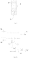
- a variable-capacity principle of the variable-capacity compressor 100 will be illustrated with reference to Figs. 1a and 1b.
- Figs. 1a and 1b show the suction port A, the compression chamber B of the variable-capacity cylinder, the variable-capacity valve 3, a first pressure passage E formed in the variable-capacity valve 3, and a pressure supply passage 41 (may also be in the form of a conduit segment) in communication with a side of the variable-capacity valve 3.
- An essential work principle thereof is as follows: When a first pressure gas (for example, having an discharge pressure Pd) is introduced into a side of the variable-capacity valve 3 (for example, a lower side thereof shown in Fig.
- variable-capacity valve 3 a gravity of the variable-capacity valve 3 will be overcome to move the variable-capacity valve 3 upward under the action of a high pressure at a lower end face thereof, such that the variable-capacity valve 3 isolates a suction passage of the variable-capacity cylinder (i.e. a suction hole 241 as follows). That is, the suction hole 241 between the suction port A and the compression chamber B is blocked by the variable-capacity valve 3, such that a low-pressure refrigerant at the suction port A cannot be transferred into the compression chamber B of the variable-capacity cylinder, i.e. the variable-capacity cylinder cannot suck in the low-pressure refrigerant.
- variable-capacity valve 3 moves upward, the first pressure passage E communicates the pressure supply passage 41 with the compression chamber B, such that the first pressure gas is sucked into the compression chamber B.
- the variable-capacity cylinder is provided with a sliding vane groove, a sliding vane 29 is disposed in the sliding vane groove, and a part of the sliding vane groove located at a tail of the sliding vane is configured as a sliding vane chamber 242; the sliding vane chamber 242 contains the discharge pressure, the tail (i.e. an end of the sliding vane 29 far away from a center of the variable-capacity cylinder) and a head (i.e.
- variable-capacity compressor 100 operates in a partial capacity work mode.
- variable-capacity valve 3 When a second pressure gas (for example, having a suction pressure Ps) is introduced into the above-described side of the variable-capacity valve 3, the lower end face of the variable-capacity valve 3 is subjected to a low pressure, in which case the variable-capacity valve 3 moves downward under the action of its own gravity, the compression chamber B and the first pressure passage E are staggered in an up-and-down direction, the compression chamber B is re-communicated with the suction port A previously blocked by the variable-capacity valve 3, and the low-pressure refrigerant may enter the compression chamber B of the variable-capacity cylinder via the suction port A.
- a second pressure gas for example, having a suction pressure Ps
- variable-capacity compressor 100 operates in a full capacity work mode.
- the present disclosure changes the force situation of the sliding vane 29 by controlling an inner pressure of the variable-capacity cylinder, thus realizing contact of the sliding vane 29 with or separation thereof from the piston 27, so as to achieve loading or unloading of the variable-capacity cylinder.
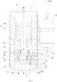
- variable-capacity compressor 100 according to one specific embodiment of the present invention will be described below referring to Figs. 2 to 11 in combination with the above variable-capacity principle.
- the variable-capacity compressor 100 is configured as a vertical compressor (as shown in Fig. 2 ), i.e. a compressor in which a central axis of a cylinder is perpendicular to a mounting surface such as a ground surface.
- the variable-capacity compressor 100 may also be configured as a horizontal compressor (not illustrated), in which case the central axis of the cylinder is substantially parallel to the mounting surface such as the ground surface.
- the case where the variable-capacity compressor 100 is configured as the vertical compressor is taken as an example for illustration.
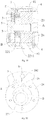
- the variable-capacity compressor includes the housing 1, an electric motor 5, the compression mechanism and a liquid reservoir 6.
- An inner space of the housing 1 may be a high pressure space having the discharge pressure.
- the liquid reservoir 6 is disposed outside the housing 1.
- the electric motor 5 and the compression mechanism are both disposed in the housing 1, and the electric motor 5 is located above the compression mechanism.
- the electric motor 5 includes a stator 51 and a rotor 52, and the rotor 52 may be rotatably disposed in the stator 51.
- the compression mechanism includes the main bearing 21, a cylinder assembly, the auxiliary bearing 22, the piston 27, the sliding vane 29 and a crankshaft 26.
- the main bearing 21 is disposed to an upper end of the cylinder assembly and the auxiliary bearing 22 is disposed to a lower end of the cylinder assembly.
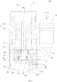
- the cylinder assembly includes two cylinders and a partition plate 25 disposed between the two cylinders. Each cylinder has a working chamber 28 and the sliding vane groove, and the sliding vane groove may extend in a radial direction of the working chamber 28.
- the piston 27 is disposed in the working chamber 28, the sliding vane 29 is movably disposed in the sliding vane groove, and the head of the sliding vane 29 is configured to abut against the outer circumferential wall of the piston 27.
- the crankshaft 26 has an upper end connected to the rotor 52 and a lower end penetrating the main bearing 21, the cylinder assembly and the auxiliary bearing 22.
- the rotor 52 may drive the piston 27 fitted over an eccentric portion of the crankshaft 26 to roll along an inner wall of the working chamber 28 via the crankshaft 26 to perform compression of the refrigerant entering the working chamber 28.
- the partition plate 25 may be one separate component, or may be constituted by a plurality of components.
- the liquid reservoir 6 is connected to a first cylinder 23 and a second cylinder 24 via two first suction conduits 61 respectively, such that a refrigerant to be compressed (i.e. the low-pressure refrigerant) is introduced into the working chambers 28 of the first cylinder 23 and the second cylinder 24 respectively.
- a refrigerant to be compressed i.e. the low-pressure refrigerant
- the suction port A is formed in the variable-capacity cylinder, and is in communication with the suction pressure all the time.
- the variable-capacity compressor 100 is configured as a multi-cylinder compressor.
- Figs. 2 and 3 show a dual-cylinder compressor for an explanatory and illustrative purpose, but after reading the following technical solution, it is apparent to those skilled in the art to understand that the solution may be applied to a technical solution of three cylinders or more cylinders, and it is also within the scope of the present disclosure.
- the case where the variable-capacity compressor 100 is configured as the dual-cylinder compressor is taken as an example for illustration.
- the above two cylinders are referred to as the first cylinder 23 and the second cylinder 24 respectively.
- At least one of the first cylinder 23 and the second cylinder 24 is configured as the variable-capacity cylinder (the corresponding working chamber 28 thereof is referred to as the compression chamber B).
- the upper first cylinder 23 is configured as a normally operating cylinder
- the lower second cylinder 24 is configured as the variable-capacity cylinder.
- the first cylinder 23 is always in operation, regardless of whether the second cylinder 24 is in operation or not. That is, the sliding vane 29 in the first cylinder 23 always abuts against the piston 27 to perform the compression of the refrigerant entering therein.
- the tail of the sliding vane 29 of the normally operating cylinder may be provided with a spring member to facilitate a smooth start-up of the variable-capacity compressor 100.
- the compression mechanism is provided with the pressure supply passage 41, as shown in Figs. 2 and 3 , and the pressure supply passage 41 is formed in the auxiliary bearing 22, and used for supplying the first pressure gas or the second pressure gas, in which the pressure of the first pressure gas is greater than that of the second pressure gas.
- the first pressure gas is a refrigerant having the discharge pressure after compressed by the variable-capacity compressor 100
- the second pressure gas is a refrigerant having the suction pressure sucked to be compressed by the variable-capacity compressor 100.
- the sliding vane chamber 242 is in communication with the housing 1, the sliding vane chamber 242 has the discharge pressure, and that is, the tail of the sliding vane 29 is subjected to the discharge pressure.
- the sliding vane chamber 242 is preferably in direct communication with the housing 1, in which case, an outer side of the sliding vane chamber 242 is opened.
- the structure of the sliding vane chamber 242 is simplified.
- the sliding vane 29 may be in direct contact with lubrication oil in an oil sump at a bottom of the housing 1 through the sliding vane chamber 242, which results in a good lubricating effect on the sliding vane 29, and further ensures reliability and performance of the variable-capacity compressor 100 over a long period of operation.
- a direction “outer” may be construed as a direction far away from a center of a cylinder, and the opposite direction thereof is defined as “inner”.
- the variable-capacity valve 3 is movable in a vertical direction, so as to achieve communication and isolation between the suction port A and the compression chamber B.
- the variable-capacity valve 3 is provided with the first pressure passage E, and the first pressure passage E may be configured as an inverted-L shape as shown in Figs.2 and 3 , which is not limited thereto.
- the first pressure passage E is in communication with the pressure supply passage 41, and when the variable-capacity valve 3 is located in the isolation position, the pressure supply passage 41 supplies the first pressure gas into the compression chamber B through the first pressure passage E.
- the pressure of the first pressure gas is substantially equal to the discharge pressure at the tail of the sliding vane 29, which does not cause the differential pressure, such that the head of the sliding vane 29 in the variable-capacity cylinder is separated from the piston 27, in which case the variable-capacity cylinder is not in operation (i.e. unloaded).
- the variable-capacity valve 3 when the variable-capacity valve 3 is located in the communication position, the low-pressure refrigerant from the liquid reservoir 6 may enter the compression chamber B of the variable-capacity cylinder through the suction port A, while the second pressure gas may not enter the compression chamber B through the first pressure passage E.
- variable-capacity valve 3 may be movable in a horizontal direction (not illustrated).
- variable-capacity compressor 100 is adjusted by making the variable-capacity cylinder participate in or not participate in the compression operation, such that variable-capacity operation of the variable-capacity compressor 100 is achieved.
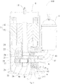
- the suction hole 241 and an accommodating chamber 221 are formed in the compression mechanism, and the variable-capacity valve 3 may be disposed to at least one of the partition plate 25, the main bearing 21, the auxiliary bearing 22, the first cylinder 23 and the second cylinder 24.
- a first end of the suction hole 241 (for example, a right end in Figs.
- the suction port A which is configured to communicate the suction port A with the compression chamber B to introduce the refrigerant into the compression chamber B
- a second end of the suction hole 241 is in communication with the accommodating chamber 221
- the accommodating chamber 221 is formed in the auxiliary bearing 22, penetrates an upper end face of the auxiliary bearing 22, and is in communication with the suction hole 241, in which the variable-capacity valve 3 is movably disposed in the accommodating chamber 221, and may move upward into the suction hole 241 to isolate the suction port A from the compression chamber B
- the accommodating chamber 221 is in communication with the pressure supply passage 41 (for example, in Figs.
- the pressure supply passage 41 is in communication with a lower portion of the accommodating chamber 221), when the first pressure gas is supplied into the pressure supply passage 41, the variable-capacity valve 3 moves from the communication position to the isolation position, and when the second pressure gas is supplied into the pressure supply passage 41, the variable-capacity valve 3 is maintained in the communication position. Thereby, the movement of the variable-capacity valve 3 is achieved by supplying different pressure gases into the pressure supply passage 41.
- the variable-capacity compressor 100 further includes at least one spring 7 disposed between the variable-capacity valve 3 and an inner wall of the accommodating chamber 221.
- the spring 7 is disposed between a bottom of the variable-capacity valve 3 and a bottom wall of the accommodating chamber 221, and the spring 7 may be configured to normally pull the variable-capacity valve 3 towards a direction of the communication position. It should be understood that, the number of the spring 7 depends on an elastic force as practically required.
- variable-capacity valve 3 overcomes the gravity and the elastic force of the spring 7 under the action of the high pressure at the lower end face of the variable-capacity valve 3, moves upward into the suction hole 241 of the second cylinder 24, and isolates the suction port A from the compression chamber B, as shown in Fig.
- the compression chamber B is in communication with the accommodating chamber 221 through the first pressure passage E in the variable-capacity valve 3
- the first pressure gas is introduced into the pressure supply passage 41 through the accommodating chamber 221
- the head and the tail of the sliding vane 29 of the second cylinder 24 are both subjected to the discharge pressure, which does not cause the differential pressure, such that the head of the sliding vane 29 is separated from the piston 27 in second cylinder 24, and the second cylinder 24 does not participate in the compression operation, in which case the variable-capacity compressor 100 operates in the partial capacity work mode.
- variable-capacity valve 3 When the second pressure gas (having the suction pressure Ps) is introduced into the accommodating chamber 221, the variable-capacity valve 3 is retracted into the accommodating chamber 221 under the action of the spring 7 and the gravity, and as shown in Fig. 3 , the first pressure passage E is sealed by the inner wall of the accommodating chamber 221, in which case the compression chamber B of the second cylinder 24 is in communication with the suction port A, and the compression chamber B sucks the low-pressure refrigerant (having the suction pressure).
- variable-capacity compressor 100 Since the tail of the sliding vane 29 is in communication with the discharge pressure of the inner space of the housing 1, the head of the sliding vane 29 abuts against the outer circumferential wall of the piston 27 under the action of the pressure at the tail thereof, and the variable-capacity cylinder participates in the compression operation, in which case the variable-capacity compressor 100 operates in the dual-cylinder work mode, and the work capacity is the full capacity.
- a magnetic material member 8 is disposed to the tail of the sliding vane groove, such as a magnet, etc.
- the magnetic material member 8 may be located in the sliding vane groove of the variable-capacity cylinder. Therefore, when the pressures at two ends of the sliding vane 29 is substantially equal or the differential pressure is small, the sliding vane 29 in the variable-capacity cylinder may be attracted by the magnetic material member 8, such that the head of the sliding vane 29 is separated from the piston 27, so as to avoid the collision of the head of the sliding vane 29 and the piston 27.
- the sliding vane 29 When a thrust force on the sliding vane 29 due to the differential pressure at two ends of the sliding vane 29 is greater than an attraction force of the magnetic material member 8 to the sliding vane 29, the sliding vane 29 will move inward and abuts against the piston 27 to achieve the compression.
- the magnetic material member 8 may also be disposed at other corresponding positions of the tail of the sliding vane 29, for example, to the main bearing 21, to the auxiliary bearing 22, or to the partition plate 25, etc.
- a diameter of the second end of the suction hole 241 is denoted as d 1 , in which case the suction hole 241 is a circular hole, but is not limited thereto.
- a cross section of the variable-capacity valve 3 may be in the shape of a polygon, such as a square or the like.
- the cross section of the variable-capacity valve 3 is configured to be in the shape of a rectangle, in which case a width of the variable-capacity valve 3 is denoted as s, in which, s and d 1 satisfy: s>d 1 , such that the variable-capacity valve 3 may completely seal the suction hole 241.
- variable-capacity valve 3 may also be in the shape of a cylinder, as shown in Figs. 5 and 8 , a diameter of the variable-capacity valve 3 is denoted as d 2 , in which, d 1 and d 2 satisfy: d 2 >d 1 . Further, d 1 and d 2 satisfy: d 2 ⁇ d 1 +0.5mm. Further, d 1 and d 2 satisfy: d 2 ⁇ d 1 +1mm. And further, d 1 and d 2 may also satisfy: d 2 ⁇ d 1 +2mm, thus ensuring that the variable-capacity valve 3 has a certain sealing length in a circumferential direction thereof. Preferably, a central axis of the variable-capacity valve 3 intersects a central axis of the suction hole 241.
- the pressure supply passage 41 extends horizontally, and when the variable-capacity valve 3 is located in the communication position, an inner wall of the pressure supply passage 41 (for example, a bottom wall in Fig. 6 ) at a side of the pressure supply passage 41 far away from the center of the variable-capacity valve 3 is spaced apart from a corresponding end face (for example, a lower end face in Fig. 6 ) of the variable-capacity valve 3.
- the gas introduced via the pressure supply passage 41 may act on the above corresponding end face of the variable-capacity valve 3, such that the variable-capacity valve 3 may move smoothly in the accommodating chamber 221.
- the spring 7 may not be disposed between the lower end face of the variable-capacity valve 3 and the bottom wall of the accommodating chamber 221, and the variable-capacity valve 3 achieves the up-and-down movement under the action of its own gravity and the pressure of the gas exerted on the lower end face of the variable-capacity valve 3.
- a stop structure 2211 such as a step part may be disposed to the inner wall of the accommodating chamber 221, and the step part is spaced apart from the inner wall at the above-described side of the pressure supply passage 41.
- the variable-capacity valve 3 When the variable-capacity valve 3 is located in the communication position, the variable-capacity valve 3 abuts against the step part, in which case the variable-capacity valve 3 may be supported on the step part, without contacting the inner wall at the above-described side of the pressure supply passage 41.
- stop structure 2211 of the accommodating chamber 221 may also be a protrusion (not illustrated), etc., as long as the structure may prevent the variable-capacity valve 3 from moving to contact the inner wall at the above-described side of the pressure supply passage 41.
- the first pressure gas or the second pressure gas may be introduced to the lower end face of the variable-capacity valve 3 directly, in which case a central axis of an end of the pressure supply passage 41 connected to the accommodating chamber 221 may be perpendicular to a bottom wall of the accommodating chamber 221, and the variable-capacity valve 3 may contact the bottom wall of the accommodating chamber 221.
- the first pressure gas or the second pressure gas supplied by the pressure supply passage 41 may directly act on the lower end face of the variable-capacity valve 3, so as to ensure that the variable-capacity valve 3 is movable between the communication position and the isolation position.
- the compression mechanism is provided with a valve base 9, in which the variable-capacity valve 3 is disposed on the valve base 9.
- the valve base 9 is disposed to a lower end of the auxiliary bearing 22, the valve base 9 and the auxiliary bearing 22 are two separated parts, and the pressure supply passage 41 and the accommodating chamber 221 may both be formed in the valve base 9, so as to simply the processing of the auxiliary bearing 22.
- a communication hole for communicating the accommodating chamber 221 and the suction hole 241 is formed at a position of the auxiliary bearing 22 corresponding to the accommodating chamber 221, and the variable-capacity valve 3 may enter the suction hole 241 via the communication hole to isolate the suction port A from the compression chamber B.
- the valve base 9 may be assembled to the auxiliary bearing 22 in a sealing manner, and for example, an upper end face of the valve base 9 and the lower end face of the auxiliary bearing 22 are both subjected to finish machining, so as to ensure the sealing between the upper end face of the valve base 9 and the lower end face of the auxiliary bearing 22 when assembled; alternatively, the sealing may be ensured by providing a sealing ring, a gasket or the like between the valve base 9 and the auxiliary bearing 22.
- variable-capacity valve 3 is disposed in the partition plate 25, and specifically, the accommodating chamber 221 and the pressure supply passage 41 are both formed in the partition plate 25; the pressure supply passage 41 extends in a horizontal direction; the accommodating chamber 221 penetrate a lower end face of the partition plate 25 and is in communication with the suction hole 241 of the variable-capacity cylinder (i.e. the second cylinder 24); the variable-capacity valve 3 is disposed in the accommodating chamber 221 and movable in the up-and-down direction, and may move downward into the suction hole 241 to isolate the suction port A from the compression chamber B.
- at least one spring 7 is disposed between a top of the variable-capacity valve 3 and a top wall of the accommodating chamber 221, and the spring 7 may be configured to normally push the variable-capacity valve 3 towards the isolation position.
- the gas force exerted on an upper end face of the variable-capacity valve 3 overcomes the elastic force of the spring 7 to press the variable-capacity valve 3 into the second cylinder 24 to isolate the suction port A from the compression chamber B, and the compression chamber B is in communication with the pressure supply passage 41 through the first pressure passage E, such that the first pressure gas may enter the compression chamber B, in which case the head and the tail of the sliding vane 29 of the second cylinder 24 are both subjected to the discharge pressure, the sliding vane 29 is held in the sliding vane groove (for example, by means of the above magnetic material member 8), and the head of the sliding vane 29 does not contact the outer circumferential wall of the piston 27, such that the second cylinder 24 is unloaded.
- the spring 7 overcomes the gravity of the variable-capacity valve 3 to pull the variable-capacity valve 3 into the accommodating chamber 221 of the partition plate 25, the first pressure passage E is sealed by the inner wall of the accommodating chamber 221, and the suction port A is in communication with the compression chamber B through the suction hole 241, such that the low-pressure refrigerant may enter the compression chamber B, and due to the differential pressure between the head and the tail of the sliding vane 29 of the second cylinder 24, the sliding vane 29 may keep abutting against the outer circumferential wall of the piston 27 under the action of the differential pressure, so as to perform the compression of the refrigerant entering the compression chamber B.
- a displacement (i.e. the capacity) of the variable-capacity cylinder is denoted as q
- an overall displacement of the variable-capacity compressor 100 is denoted as Q, in which, q and Q satisfy: q/Q ⁇ 50%.
- an adjustment of the partial capacity work mode may be achieved by designing a capacity ratio of the first cylinder 23 and the second cylinder 24. For example, if the capacity of the first cylinder 23 is equal to that of the second cylinder 24, i.e.
- variable-capacity compressor 100 when the variable-capacity cylinder participates in the compression operation, the suction passage of the variable-capacity cylinder is substantially consistent with that of the normally operating cylinder, which is substantially consistent with a suction design of a conventional dual-cylinder rotary compressor, that is, the first suction conduit 61 communicated with the liquid reservoir 6 of the variable-capacity cylinder has the same design as the first suction conduit 61 communicated with the liquid reservoir 6 of the normally operating cylinder, which avoids a problem of increased suction resistance due to additional lengthening of the first suction conduit 61 or installation of a control valve, and reduces the cost; the whole variable-capacity compressor 100 is not easy to generate vibration, such that problems of noise and reliability are avoided.
- an efficiency of the variable-capacity cylinder in operation is not affected, so as to ensure the performance of the variable-capacity compressor 100 in the full capacity work mode.
- the first cylinder 23 and the second cylinder 24 may both be configured as the variable-capacity cylinder, for example, as shown in Fig. 11 , in which case two variable-capacity valves 3 are provided, and each of the variable-capacity valves 3 is respectively configured to be movable between the communication position where the compression chamber B of the respective cylinder is communicated with the suction port A of the respective cylinder and the isolation position where the compression chamber B is isolated from the suction port A.
- Functions and control principles of the two variable-capacity valves 3 are described above, which will not be described in detail herein.
- the first pressure gas may not be introduced into two pressure supply passages 41 simultaneously, that is, the unloading situation may not occur to the two variable-capacity cylinders simultaneously, to ensure that at least one cylinder is in operation at each moment.
- the pressure supply passage 41 may be correspondingly added according to the number of the variable-capacity cylinder.
- variable-capacity compressor 100 there are three specific work modes for the variable-capacity compressor 100 as follows. First, when the second pressure gas is introduced into the pressure supply passage 41 corresponding to the first cylinder 23, and the first pressure gas is introduced into the pressure supply passage 41 corresponding to the second cylinder 24, the first cylinder 23 participates in the compression operation while the second cylinder 24 is unloaded, in which case the variable-capacity compressor 100 operates in the partial capacity work mode, and the capacity of the variable-capacity compressor 100 is the capacity of the first cylinder 23; second, when the first pressure gas is introduced into the pressure supply passage 41 corresponding to the first cylinder 23, and the second pressure gas is introduced into the pressure supply passage 41 corresponding to the second cylinder 24, the first cylinder 23 does not participate in the compression operation while the second cylinder 24 participates in the compression operation, in which case the variable-capacity compressor 100 operates in the partial capacity work mode, and the capacity of the variable-capacity compressor 100 is the capacity of the second cylinder 24; third, when the second pressure gas is introduced into the pressure supply
- variable-capacity principle of the variable-capacity compressor 100 will be illustrated below in combination with Figs. 12a and 12b.
- Figs. 12a and 12b show the suction port A, the compression chamber B of the variable-capacity cylinder, the variable-capacity valve 3, the first pressure passage E and a second pressure passage D formed in the variable-capacity valve 3, and the pressure supply passage 41 (may also be in the form of a conduit segment) communicated with a side of the variable-capacity valve 3, in which the second pressure passage D and the first pressure passage E are not in communication with each other, and when the variable-capacity valve 3 is located in the communication position, the second pressure passage D communicates the compression chamber B with the suction port A.
- variable-capacity valve 3 When the first pressure gas (for example, having the discharge pressure Pd) is introduced into the side of the variable-capacity valve 3 (for example, a lower side in Fig. 12a ) through the pressure supply passage 41, the variable-capacity valve 3 will overcome its own gravity to move upward under the action of the high pressure at the lower end face of the variable-capacity valve 3, such that the second pressure passage D of the variable-capacity valve 3 is staggered with respect to the suction port A and the compression chamber B of the variable-capacity cylinder, and the low pressure at the suction port A cannot be transferred into the compression chamber B, in which case the variable-capacity cylinder cannot suck in the low-pressure refrigerant.
- the first pressure passage E communicates the pressure supply passage 41 with the compression chamber B, such that the first pressure gas is sucked into the compression chamber B.
- the head of the sliding vane 29 in the variable-capacity cylinder is separated from the outer circumferential wall of the piston 27 in the compression chamber B, and the variable-capacity cylinder does not participate in the compression operation.
- the compressor operates in the partial capacity work mode.
- variable-capacity valve 3 When the second pressure gas (for example, having the suction pressure Ps) is introduced into the above-described side of the variable-capacity valve 3, the lower end face of the variable-capacity valve 3 is subjected to the low pressure, in which case the variable-capacity valve 3 moves downward under the action of its own gravity, such that the compression chamber B is staggered with respect to the first pressure passage E, while the compression chamber B is in communication with the suction port A through the second pressure passage D, that is, the low-pressure refrigerant enters the compression chamber B of the variable-capacity cylinder through the suction port A and the second pressure passage D.
- the second pressure gas for example, having the suction pressure Ps
- variable-capacity compressor 100 operates in the full capacity work mode.
- variable-capacity compressor 100 according to another specific embodiment of the present invention will be described below in combination with the above variable-capacity principle and referring to Fig. 13 .
- the first pressure passage E and the second pressure passage D are respectively formed in the variable-capacity valve 3, the first pressure passage E is configured to have the substantially inverted-L shape, and the second pressure passage D is located above the first pressure passage E and extends in the horizontal direction.
- the suction port A is in communication with the compression chamber B through the second pressure passage D; when the variable-capacity valve 3 is located in the isolation position, the suction port A is isolated from the compression chamber B by the variable-capacity valve 3, and the first pressure gas introduced via the pressure supply passage 41 may enter the compression chamber B through the first pressure passage E, such that the variable-capacity cylinder is unloaded.
- a specific shape and size of the second pressure passage D may be adapted to a shape and size of the suction hole 241, such that the low-pressure refrigerant may be better introduced into the compression chamber B.
- variable-capacity compressor 100 may be the same as that of the variable-capacity compressor 100 referring to the description of the above-described embodiment, which will not be described in detail herein.
- variable-capacity principle of the variable-capacity compressor 100 will be illustrated below in combination with Figs. 14a and 14b .
- Figs. 14a and 14b show the suction port A, the working chamber 28 of the first cylinder 23, the compression chamber B of the variable-capacity cylinder (for example, the second cylinder 24), the variable-capacity valve 3, the first pressure passage E formed in the variable-capacity valve 3, and the pressure supply passage 41 (may also be in the form of a conduit segment) communicating with a side of the variable-capacity valve 3.
- the present embodiment distinguishes from the above first embodiment only in that the first cylinder 23 and the second cylinder 24 are both connected to the same suction port A.
- variable-capacity compressor 100 of the present embodiment is as follows: When the first pressure gas (for example, having the discharge pressure Pd) is introduced into one side of the variable-capacity valve 3 (for example, a lower side in Fig. 14a ), the variable-capacity valve 3 will overcome its own gravity to move upward under the action of the high pressure at the lower end face of the variable-capacity valve 3, such that the variable-capacity valve 3 isolates the suction passage of the variable-capacity cylinder, and the low pressure at the suction port A may not be transferred into the compression chamber B, in which case the variable-capacity valve 3 cannot suck in the low-pressure refrigerant.
- the first pressure gas for example, having the discharge pressure Pd
- the variable-capacity valve 3 will overcome its own gravity to move upward under the action of the high pressure at the lower end face of the variable-capacity valve 3, such that the variable-capacity valve 3 isolates the suction passage of the variable-capacity cylinder, and the low pressure at
- the variable-capacity valve 3 moves upward, the first pressure passage E communicates the pressure supply passage 41 with the compression chamber B, such that the first pressure gas in the pressure supply passage 41 is sucked into the compression chamber B.
- the head of the sliding vane 29 is separated from the outer circumferential wall of the piston 27, and the variable-capacity cylinder does not participate in the compression operation.
- the variable-capacity compressor 100 operates in the partial capacity work mode.
- variable-capacity valve 3 When the second pressure gas (for example, having the suction pressure Ps) is introduced into the above-described side of the variable-capacity valve 3, the lower end face of the variable-capacity valve 3 is subjected to the low pressure, in which case the variable-capacity valve 3 moves downward under the action of its own gravity, such that the compression chamber B is staggered with respect to the first pressure passage E in the up-and-down direction, and the compression chamber B is re-communicated with the suction port A previously blocked by the variable-capacity valve 3, in which case the variable-capacity cylinder may normally suck in the low-pressure refrigerant.
- the second pressure gas for example, having the suction pressure Ps
- the sliding vane 29 is under the action of the differential pressure between the discharge pressure at the tai of the sliding vane 29 and the suction pressure at the head of the sliding vane 29, and the head of the sliding vane 29 abuts against the outer circumferential wall of the piston 27, such that the variable-capacity cylinder normally participates in the compression operation.
- the variable-capacity compressor 100 operates in the full capacity work mode.
- the first cylinder 23 is configured as the normally operating cylinder, i.e. regardless of the state of the second cylinder 24, the first cylinder 23 operates normally, that is, performs the compression of the low-pressure refrigerant sucked into the working chamber 28 via the suction port A.
- variable-capacity compressor 100 according to a further specific embodiment of the present invention will be described below in combination with the above variable-capacity principle and referring to Figs. 15 to 20 .
- the first cylinder 23 and the second cylinder 24 are both connected to a second suction conduit 62 (i.e. the suction conduit).
- the refrigerant to be compressed from the liquid reservoir 6 i.e. the low-pressure refrigerant
- the suction port A is formed in the partition plate 25
- the second suction conduit 62 is connected between the liquid reservoir 6 and the partition plate 25, and the suction port A is in communication with the suction pressure all the time.
- the suction hole 241 is formed in the partition plate 25, and the suction port A is configured to be in communication with the working chambers 28 of the first cylinder 23 and the second cylinder 24 through the suction hole 241.
- the suction hole 241 includes a first suction segment 2411 and a second suction segment 2412 connected to each other, in which, the first suction segment 2411 extends in an inner and outer direction of the partition plate 25 (for example, in a radial direction of the partition plate 25), and a first end of the first suction segment 2411 (for example, a right end thereof in Figs.
- the second suction segment 2412 is connected to a second end of the first suction segment 2411 (for example, a left end thereof in Figs. 15 and 16 ) and extends in an axial direction of the partition plate 25, and a first end of the second suction segment 2412 (for example, a lower end thereof in Figs. 15 and 16 ) penetrates the lower end face of the partition plate 25 and is in communication with the accommodating chamber 221 for accommodating the variable-capacity valve 3.
- the communication holes in communication with the second suction segment 2412 of the suction hole 241 are formed in inner walls of the working chambers 28 of the first cylinder 23 and the second cylinder 24.
- the communication hole is configured as an oblique incision.
- the pressure supply passage 41 is formed in the second cylinder 24.
- variable-capacity valve 3 when the second pressure gas is introduced to the lower end face of the variable-capacity valve 3 through the pressure supply passage 41, the variable-capacity valve 3 is retracted to the lower part of the accommodating chamber 221 under the action of the spring 7 and the gravity, and the variable-capacity valve 3 avoids the communication hole, in which case the compression chamber B of the variable-capacity cylinder (i.e. the second cylinder 24) is in communication with the suction port A through the communication hole and the suction hole 241, and the compression chamber B sucks in the low-pressure refrigerant.
- the compression chamber B of the variable-capacity cylinder i.e. the second cylinder 24
- variable-capacity compressor 100 Since the tail of the sliding vane 29 of the second cylinder 24 is in communication with the inner space of the housing 1 all the time, the head of the sliding vane 29 will abut against the outer circumferential wall of the piston 27 in the second cylinder 24 under the action of the pressure at the tail thereof, and the variable-capacity cylinder participates in the compression operation, in which case the variable-capacity compressor 100 operates in the dual-cylinder work mode, and the working capacity is the full capacity.
- variable-capacity valve 3 When the first pressure gas is introduced to the lower end face of the variable-capacity valve 3 through the pressure supply passage 41, the variable-capacity valve 3 overcomes its own gravity and the force of the spring 7 under the action of the pressure at the lower end thereof, and enters an upper part of the accommodating chamber 221 to close the second suction segment 2412, so as to isolate the communication hole from the second suction segment 2412, that is, to isolate the communication between the compression chamber B of the second cylinder 24 and the suction port A of the partition plate 25, as shown in Fig.
- the first pressure passage E in the variable-capacity valve 3 is in communication with the compression chamber B through the communication hole
- the first pressure gas introduced via the pressure supply passage 41 may enter the compression chamber B of the second cylinder 24 through the first pressure passage E, and the head and the tail of the sliding vane 29 are both subjected to the discharge pressure, without generating the differential pressure, such that the head of the sliding vane 29 is separated from the piston 27, and the second cylinder 24 does not participate in the compression operation, in which case the variable-capacity compressor 100 operates in the partial capacity work mode.
- the pressure supply passage 41 is formed in the auxiliary bearing 22, the pressure supply passage 41 is located below the accommodating chamber 221 and a section area of an end of the pressure supply passage 41 connected to the accommodating chamber 221 is smaller than that of the accommodating chamber 221, and the first pressure gas or the second pressure gas supplied via the pressure supply passage 41 may act directly on the lower end face of the variable-capacity valve 3 all the time, such that the variable-capacity valve 3 may smoothly move upward and downward in the accommodating chamber 221.
- the spring 7 may not be disposed between the variable-capacity valve 3 and the inner wall of the accommodating chamber 221.
- a diameter of a minimum circumcircle of the second suction segment 2412 is denoted as d 1
- a sectional shape of the variable-capacity valve 3 may be polygonal, such as a square or the like.
- a width of the variable-capacity valve 3 is denoted as s, in which, s and d 1 satisfy: s>d 1 , such that the variable-capacity valve 3 may completely seal the suction hole 241.
- variable-capacity valve 3 may be cylindrical, as shown in Fig. 20 , a diameter of the variable-capacity valve 3 is denoted as d 2 , in which, d 1 and d 2 satisfy: d 2 >d 1 . Further, d 1 and d 2 satisfy: d 2 ⁇ d 1 +0.5mm. Further, d 1 and d 2 satisfy: d 2 ⁇ d 1 +1mm. And further, d 1 and d 2 may also satisfy: d 2 ⁇ d 1 +2mm.
- the end face of the variable-capacity valve 3 may abut against the corresponding end face of the partition plate 25, so as to achieve the sealed isolation between the second suction segment 2412 and the compression chamber B.
- variable-capacity valve 3 when the variable-capacity valve 3 is located in the isolation position, the variable-capacity valve 3 is configured to enter the second suction segment 2412, in which case the sectional shape of the second suction segment 2412 may be circular, correspondingly, the shape of the variable-capacity valve 3 is cylindrical, the variable-capacity valve 3 is fitted with an inner wall of the second suction segment 2412 in the circumferential direction to achieve the sealed isolation. Further, a limiting member such as the spring 7 or the like may be provided, so as to prevent the variable-capacity valve 3 from entering the suction hole 241 completely.
- the first cylinder 23 is configured as the variable-capacity cylinder, and the pressure supply passage 41 is formed in the main bearing 21.
- Fig. 18 distinguishes from Figs. 15 and 16 only in that the effect of the spring 7 is reversed.
- the spring 7 when the second pressure gas is introduced into the pressure supply passage 41, the spring 7 will overcome the gravity of the variable-capacity valve 3 to pull the variable-capacity valve 3 upward, such that the first cylinder 23 sucks air normally; when the first pressure gas is introduced into the pressure supply passage 41, the gas force exerted on the upper end face of the variable-capacity valve 3 will overcome the elastic force of the spring 7 and the gravity of the variable-capacity valve 3 to press the variable-capacity valve 3 downward, so as to isolate the suction of the first cylinder 23.
- the first cylinder 23 and the second cylinder 24 as shown in Fig. 19 are both configured as the variable-capacity cylinders, correspondingly, two variable-capacity valves 3 are provided, and the two variable-capacity valves 3 are respectively disposed in the respective cylinder. Functions and control principles of the two variable-capacity valves 3 are described above, which will not be described in detail herein.
- variable-capacity compressor 100 may be same as that of the variable-capacity compressor 100 referring to the description of the above-described embodiment, which will not be described in detail herein.
- variable-capacity valve 3 is designed in the housing 1, and when the variable-capacity valve 3 participates in the compression operation, the suction path thereof is substantially consistent with that of the conventional dual-cylinder compressor, that is, since a structure of the suction path is not changed, a suction efficiency of the variable-capacity cylinder is substantially unaffected, such that an operating efficiency of the variable-capacity cylinder is not affected, and the performance of the variable-capacity cylinder may be well ensured.
- variable-capacity compressor 100 has characteristics of simple and reasonable structure, low manufacturing cost, and high control reliability.
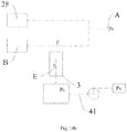
- the refrigeration device 200 includes a first heat exchanger 201, a second heat exchanger 202, a first control valve 203 and the variable-capacity compressor 100.
- the variable-capacity compressor 100 may be configured as a variable-capacity compressor 100 described referring to the embodiments of the first aspect.
- the refrigeration device 200 may be applied in an air conditioner, and the air conditioner is usually used to keep the indoor environment in a comfortable state by keeping the indoor temperature at a set temperature.
- the first control valve 203 is configured as a four-way valve, but is not limited thereto.
- a first end of the second heat exchanger 202 (for example, a right end thereof in Figs. 21 and 22 ) is connected to a first end of the first heat exchanger 201 (for example, a right end thereof in Figs. 21 and 22 );
- the first control valve 203 includes a first valve port 2031, a second valve port 2032, a third valve port 2033 and a fourth valve port 2034;
- the first valve port 2031 is connected to a second end of the first heat exchanger 201 (for example, a left end thereof in Figs. 21 and 22 );
- the third valve port 2033 is connected to a second end of the second heat exchanger 202 (for example, a left end thereof in Figs.
- an exhaust port 11 (may be in the form of a conduit segment) is formed in the housing 1 of the variable-capacity compressor 100, the exhaust port 11 is used for discharging the compressed refrigerant in the housing 1 and connected to the fourth valve port 2034, the suction port A is connected to the second valve port 2032, and the pressure supply passage 41 is connected to the suction port A or the exhaust port 11 to introduce the low-pressure refrigerant having the suction pressure Ps (i.e. the second pressure gas) or the high-pressure refrigerant having the discharge pressure Pd (i.e. the first pressure gas) into the pressure supply passage 41.
- the suction pressure Ps i.e. the second pressure gas
- Pd discharge pressure
- a throttling element 204 is disposed between the first end of the first heat exchanger 201 and the first end of the second heat exchanger 202.
- the throttling element 204 is configured as a capillary or an expansion valve.
- One of the first heat exchanger 201 and the second heat exchanger 202 is configured as a condenser, and the other is configured as an evaporator.
- the variable-capacity compressor 100 is used to compress the refrigerant.
- the condenser is used to condense the refrigerant compressed by the compressor and release the heat outwards.
- the throttling element 204 is used to reduce the pressure of the refrigerant condensed by the condenser.
- the evaporator is used to evaporate the refrigerant which has passed through the throttling element 204, and absorb the external heat.
- a refrigerating mode that the second heat exchanger 202 is in communication with the suction port A of the variable-capacity compressor 100 and meanwhile the first heat exchanger 201 is in communication with the exhaust port 11 of the variable-capacity compressor 100 can be achieved (as shown in Fig. 22 );
- a heating mode that the second heat exchanger 202 is in communication with the exhaust port 11 of the variable-capacity compressor 100 and meanwhile the first heat exchanger 201 is in communication with the suction port A can also be achieved (as shown in Fig. 21 ).
- the liquid reservoir 6 is connected to the first cylinder 23 and the second cylinder 24 of the variable-capacity compressor 100 through two first suction conduits 61 respectively.
- the first end of the pressure supply passage 41 is disposed between the first valve port 2031 of the first control valve 203 and the second end of the first heat exchanger 201, and for example, the pressure supply passage 41 of the variable-capacity compressor 100 is connected to a pipe between the first control valve 203 and the second heat exchanger 202, such that when the refrigeration device 200 operates in the refrigerating mode, the high-pressure refrigerant is introduced into the pressure supply passage 41; when the refrigeration device 200 operates in the heating mode, the low-pressure refrigerant is introduced into the pressure supply passage 41.
- the second cylinder 24 is configured as the variable-capacity cylinder.
- Fig. 22 is a schematic view of the refrigeration device 200 operating in the refrigerating mode.
- the exhaust port 11 of the variable-capacity compressor 100 is connected to the first heat exchanger 201 through the first control valve 203
- the second heat exchanger 202 is connected to the suction port A of the variable-capacity compressor 100 through the first control valve 203, in which case the pressure supply passage 41 introduces the high-pressure refrigerant to the lower end face of the variable-capacity valve 3, and the variable-capacity valve 3 moves upward into the suction hole 241 under the action of the high pressure at the lower end face of the variable-capacity valve 3 and isolates the suction port A from the compression chamber B, such that the variable-capacity cylinder cannot suck in the low-pressure refrigerant from the liquid reservoir 6; furthermore, the compression chamber B of the variable-capacity cylinder may be in communication with the high pressure of the pressure supply passage 41 through the first pressure passage E of the variable-capacity valve 3, in which case the head and
- Fig. 21 is a schematic view of the refrigeration device 200 operating in the heating mode.
- the exhaust port 11 of the variable-capacity compressor 100 is connected to the second heat exchanger 202 through the first control valve 203, and the first heat exchanger 201 is connected to the suction port A of the variable-capacity compressor 100 through the first control valve 203, in which case the pressure supply passage 41 introduces the low-pressure refrigerant to the lower end face of the variable-capacity valve 3, and without the differential pressure between the upper end and the lower end of the variable-capacity valve 3, the variable-capacity valve 3 leaves the suction hole 241 under the action of its own gravity, in which case the compression chamber B of the variable-capacity cylinder may suck in the low-pressure refrigerant from the liquid reservoir 6 through the suction hole 241.
- variable-capacity compressor 100 Since the tail of the sliding vane 29 is in communication with the discharge pressure of the inner space of the housing 1, the head of the sliding vane 29 abuts against the outer circumferential wall of the corresponding piston 27 under the action of the pressure at the tail, and the variable-capacity cylinder operates, in which case the variable-capacity compressor 100 operates in the dual-cylinder and full capacity work mode. Thus, when the refrigeration device 200 operates in different modes, the variable-capacity compressor 100 may operate in respective capacities.
- variable-capacity cylinder When the refrigeration device 200 is refrigerating, the variable-capacity cylinder does not operate; however, when the refrigeration device 200 is heating, the variable-capacity cylinder operates, such that the variable-capacity compressor 100 operates in a large capacity mode, the heating capacity of the refrigeration device 200 is improved, and particularly at a low ambient temperature, the heating capacity of the refrigeration device 200 is effectively ensured by operating in the large capacity mode. Furthermore, in this mode, the structure of the refrigeration system is simple, and the heating capacity may be improved without additional control. In addition, since the variable-capacity compressor 100 has the normally operating cylinder and the variable-capacity cylinder at the same time, the structure and control of the variable-capacity compressor 100 may be simplified.
- the refrigeration device 200 in Fig. 23 distinguishes from the refrigeration device 200 in Figs. 21 and 22 only in that the liquid reservoir 6 is connected to the first cylinder 23 and the second cylinder 24 only through one second suction conduit 62.
- Structures and work principles of other components of the refrigeration device 200 of Fig. 23 is substantially the same as the corresponding structure and work principle of the refrigeration device 200 of Figs. 21 and 22 , which will not be described in detail herein.
- the refrigeration device 200 further includes a second control valve 205; the second control valve 205 includes a first port 2051, a second port 2052 and a third port 2053; the first port 2051 is connected to the first end of the pressure supply passage 41, the second port 2052 is connected to the exhaust port 11, and the third port 2053 is connected to the suction port A.
- the first port 2051 is selectively connected to the second port 2052 or the third port 2053.
- the second control valve 205 is a three-way valve, but is not limited thereto.
- variable-capacity valve 3 will isolate the suction port A from the compression chamber B to unload the variable-capacity cylinder, but as long as the first port 2051 is in communication with the third port 2053, the suction port A will be in communication with the compression chamber B to make the variable-capacity cylinder operate.
- variable-capacity cylinder may be controlled according to practical requirements of the refrigeration device 200, such that a flexible control of the variable-capacity cylinder may be achieved. For example, a large capacity work mode when in the refrigerating mode and a small capacity work mode when in the heating mode may be achieved.
- the flexible control of capacity or power of the refrigeration device 200 may be achieved, that is, according to the load requirement of the refrigeration device 200, the variable-capacity compressor 100 may operate under a corresponding load, achieving efficient operation.
- a fluid path of the second control valve 205 may be designed to be small, as long as transfer of the pressure may be achieved.
- a flow area of the first port 2051 may be smaller than that of an input end of the first heat exchanger 201.
- first port 2051 and the input end of first heat exchanger 201 are connected to corresponding components respectively through pipes
- the flow area (may also be a circulation area or a sectional area) of the pipe of the input end of the first heat exchanger 201 is denoted as S1
- the sectional area (may also be a circulation area or a flow area) of the pipe of the second control valve 205 connected to the pressure supply passage 41 is denoted as S2, and it may be designed as S2 ⁇ S1.
- a size of the second control valve 205 may be designed to be small, and in the terms of function, size and cost, there are significant improvements.
- the input end of the first heat exchanger 201 may be understood as an inlet end when the refrigerant flows through the first heat exchanger 201.
- the input end of the first heat exchanger 201 is a left end in Fig. 24
- the input end of the first heat exchanger 201 is a right end in Fig. 24 .
- a size of the pressure supply passage 41 of the variable-capacity compressor 100 may be designed to be small, as long as the pressure supply may be achieved.
- the sectional area of the pressure supply passage 41 is smaller than that of the input end of the first heat exchanger 201.
- the compression mechanism is provided with the pressure supply conduit 4, and the pressure supply passage 41 is defined in the pressure supply conduit 4; a pipe diameter of the pressure supply conduit 4 is smaller than that of the input end of the first heat exchanger 201, and respective sectional shapes of the pressure supply conduit 4 and the pipe of the input end of the first heat exchanger 201 are preferably circular; the pipe diameter of the pressure supply conduit 4 is denoted as R, and the pipe diameter of the input end of the first heat exchanger 201 is denoted as T, in which it may be designed as R ⁇ T.
- the refrigeration device 200 improves an overall performance of the refrigeration device 200, and has characteristics of simple structure, easy control, and being reliable and easy to use.
- variable-capacity compressor 100 and the refrigeration device 200 are well known to a person skilled in the art, which will not be described in detail herein.
Landscapes
- Engineering & Computer Science (AREA)
- Mechanical Engineering (AREA)
- General Engineering & Computer Science (AREA)
- Applications Or Details Of Rotary Compressors (AREA)
Applications Claiming Priority (1)
| Application Number | Priority Date | Filing Date | Title |
|---|---|---|---|
| PCT/CN2016/073160 WO2017132824A1 (zh) | 2016-02-02 | 2016-02-02 | 变容式压缩机和具有其的制冷装置 |
Publications (3)
| Publication Number | Publication Date |
|---|---|
| EP3244065A1 EP3244065A1 (en) | 2017-11-15 |
| EP3244065A4 EP3244065A4 (en) | 2018-09-12 |
| EP3244065B1 true EP3244065B1 (en) | 2021-03-31 |
Family
ID=59499257
Family Applications (1)
| Application Number | Title | Priority Date | Filing Date |
|---|---|---|---|
| EP16840326.9A Active EP3244065B1 (en) | 2016-02-02 | 2016-02-02 | Variable displacement type compressor and refrigeration device having same |
Country Status (4)
| Country | Link |
|---|---|
| US (1) | US10502210B2 (zh) |
| EP (1) | EP3244065B1 (zh) |
| JP (1) | JP6446542B2 (zh) |
| WO (1) | WO2017132824A1 (zh) |
Families Citing this family (4)
| Publication number | Priority date | Publication date | Assignee | Title |
|---|---|---|---|---|
| CN108869287B (zh) * | 2018-07-10 | 2024-03-29 | 珠海凌达压缩机有限公司 | 变容压缩机构、压缩机及空调器 |
| CN109519379A (zh) * | 2018-12-12 | 2019-03-26 | 珠海凌达压缩机有限公司 | 一种压缩机及包括该压缩机的电器 |
| CN111828319B (zh) * | 2019-04-17 | 2021-10-08 | 上海海立电器有限公司 | 双缸两级变容压缩机 |
| CN112240302B (zh) * | 2019-07-19 | 2022-08-12 | 浙江盾安机械有限公司 | 压缩机 |
Family Cites Families (20)
| Publication number | Priority date | Publication date | Assignee | Title |
|---|---|---|---|---|
| JPS5975591U (ja) | 1982-11-15 | 1984-05-22 | 三菱重工業株式会社 | 圧縮機 |
| JPS6039793U (ja) * | 1983-08-26 | 1985-03-19 | カルソニックカンセイ株式会社 | ロ−タリコンプレツサ |
| JPH07103856B2 (ja) | 1986-09-30 | 1995-11-08 | 三菱電機株式会社 | 多気筒回転式圧縮機 |
| JPH0794832B2 (ja) * | 1988-08-12 | 1995-10-11 | 三菱重工業株式会社 | 回転式圧縮機 |
| JP2803456B2 (ja) * | 1991-10-23 | 1998-09-24 | 三菱電機株式会社 | 多気筒回転式圧縮機 |
| US6736621B2 (en) * | 2002-10-04 | 2004-05-18 | Scroll Technologies | Scroll compressor with adjustable capacity |
| KR100500985B1 (ko) * | 2003-03-06 | 2005-07-14 | 삼성전자주식회사 | 능력가변 회전압축기 |
| KR20040086892A (ko) * | 2003-03-22 | 2004-10-13 | 삼성전자주식회사 | 로터리압축기 |
| JP4398321B2 (ja) * | 2004-08-02 | 2010-01-13 | 東芝キヤリア株式会社 | 冷凍サイクル装置 |
| JP5005598B2 (ja) * | 2008-03-27 | 2012-08-22 | 東芝キヤリア株式会社 | 2気筒回転式圧縮機および冷凍サイクル装置 |
| CN201779016U (zh) * | 2010-09-02 | 2011-03-30 | 广东美芝制冷设备有限公司 | 变容式旋转压缩机 |
| CN103161729B (zh) | 2011-12-12 | 2015-10-28 | 珠海格力节能环保制冷技术研究中心有限公司 | 旋转式压缩机及空调器 |
| CN202500772U (zh) | 2011-12-31 | 2012-10-24 | 珠海格力电器股份有限公司 | 一种变频兼变容量的压缩机及使用该压缩机的空调系统 |
| CN202483880U (zh) * | 2012-01-17 | 2012-10-10 | 广东美芝制冷设备有限公司 | 两级压缩式旋转压缩机 |
| CN103256223B (zh) | 2012-02-17 | 2015-12-23 | 珠海格力节能环保制冷技术研究中心有限公司 | 变容压缩机及其控制方法、具有其的空调器和热泵热水器 |
| CN204900247U (zh) * | 2015-08-03 | 2015-12-23 | 广东美芝制冷设备有限公司 | 变容量旋转压缩机 |
| CN105570133B (zh) * | 2016-02-02 | 2019-04-26 | 广东美芝制冷设备有限公司 | 变容式压缩机和具有其的制冷装置 |
| CN105570138B (zh) * | 2016-02-02 | 2019-04-26 | 广东美芝制冷设备有限公司 | 变容式压缩机和具有其的制冷装置 |
| CN205349733U (zh) | 2016-02-02 | 2016-06-29 | 广东美芝制冷设备有限公司 | 变容式压缩机和具有其的制冷装置 |
| CN105570134B (zh) * | 2016-02-02 | 2019-04-26 | 广东美芝制冷设备有限公司 | 变容式压缩机和具有其的制冷装置 |
-
2016
- 2016-02-02 US US15/518,435 patent/US10502210B2/en active Active
- 2016-02-02 EP EP16840326.9A patent/EP3244065B1/en active Active
- 2016-02-02 WO PCT/CN2016/073160 patent/WO2017132824A1/zh active Application Filing
- 2016-02-02 JP JP2017516716A patent/JP6446542B2/ja active Active
Non-Patent Citations (1)
| Title |
|---|
| None * |
Also Published As
| Publication number | Publication date |
|---|---|
| EP3244065A4 (en) | 2018-09-12 |
| US20180045201A1 (en) | 2018-02-15 |
| US10502210B2 (en) | 2019-12-10 |
| JP6446542B2 (ja) | 2018-12-26 |
| WO2017132824A1 (zh) | 2017-08-10 |
| EP3244065A1 (en) | 2017-11-15 |
| JP2018507339A (ja) | 2018-03-15 |
Similar Documents
| Publication | Publication Date | Title |
|---|---|---|
| JP4856091B2 (ja) | 容量可変型ロータリ圧縮機及びこれを備える冷却システム | |
| EP2085617B1 (en) | Mode changing apparatus for a scroll compressor | |
| EP3244065B1 (en) | Variable displacement type compressor and refrigeration device having same | |
| JP2004301114A (ja) | ロータリ式密閉形圧縮機および冷凍サイクル装置 | |
| KR20080066905A (ko) | 다단 압축식 로터리 컴프레서의 제조 방법 | |
| EP3115611B1 (en) | Two-stage rotary compressor and refrigerating circulation device having same | |
| CN203272136U (zh) | 单缸多级压缩机 | |
| US20100319394A1 (en) | Compressor and refrigeration apparatus | |
| EP3392507B1 (en) | Variable-capacity cylinder with sliding vane control structure and variable-capacity compressor | |
| JP6605140B2 (ja) | ロータリ圧縮機および冷凍サイクル装置 | |
| CN107191372B (zh) | 旋转式压缩机和具有其的制冷装置 | |
| KR100620044B1 (ko) | 로터리 압축기의 용량 가변 장치 | |
| JP2007146747A (ja) | 冷凍サイクル装置 | |
| KR100724452B1 (ko) | 용량 가변형 로터리 압축기 | |
| KR100677522B1 (ko) | 로터리 압축기의 용량 가변 장치 | |
| KR101587174B1 (ko) | 로터리 압축기 | |
| CN107489618B (zh) | 旋转式压缩机和具有其的空调系统 | |
| CN111120321A (zh) | 压缩机和制冷系统 | |
| KR100677527B1 (ko) | 로터리 압축기 | |
| JP4024056B2 (ja) | ロータリコンプレッサ | |
| KR100724451B1 (ko) | 용량 가변형 로터리 압축기 | |
| CN109595166B (zh) | 压缩机 | |
| KR20070072104A (ko) | 용량 가변형 로터리 압축기 | |
| CN110836182A (zh) | 容量控制式旋转压缩机和冷冻循环装置 | |
| JPWO2016181559A1 (ja) | 冷媒圧縮機及びそれを備えた蒸気圧縮式冷凍サイクル装置 |
Legal Events
| Date | Code | Title | Description |
|---|---|---|---|
| STAA | Information on the status of an ep patent application or granted ep patent |
Free format text: STATUS: UNKNOWN |
|
| STAA | Information on the status of an ep patent application or granted ep patent |
Free format text: STATUS: THE INTERNATIONAL PUBLICATION HAS BEEN MADE |
|
| PUAI | Public reference made under article 153(3) epc to a published international application that has entered the european phase |
Free format text: ORIGINAL CODE: 0009012 |
|
| STAA | Information on the status of an ep patent application or granted ep patent |
Free format text: STATUS: REQUEST FOR EXAMINATION WAS MADE |
|
| 17P | Request for examination filed |
Effective date: 20170309 |
|
| AK | Designated contracting states |
Kind code of ref document: A1 Designated state(s): AL AT BE BG CH CY CZ DE DK EE ES FI FR GB GR HR HU IE IS IT LI LT LU LV MC MK MT NL NO PL PT RO RS SE SI SK SM TR |
|
| AX | Request for extension of the european patent |
Extension state: BA ME |
|
| R17P | Request for examination filed (corrected) |
Effective date: 20170309 |
|
| A4 | Supplementary search report drawn up and despatched |
Effective date: 20180814 |
|
| RIC1 | Information provided on ipc code assigned before grant |
Ipc: F04C 28/06 20060101ALI20180806BHEP Ipc: F04C 18/356 20060101ALI20180806BHEP Ipc: F04C 28/12 20060101AFI20180806BHEP Ipc: F04C 23/00 20060101ALI20180806BHEP |
|
| DAV | Request for validation of the european patent (deleted) | ||
| DAX | Request for extension of the european patent (deleted) | ||
| RIC1 | Information provided on ipc code assigned before grant |
Ipc: F04C 18/356 20060101ALI20201014BHEP Ipc: F04C 23/00 20060101ALI20201014BHEP Ipc: F04C 28/06 20060101ALI20201014BHEP Ipc: F04C 28/12 20060101AFI20201014BHEP |
|
| GRAP | Despatch of communication of intention to grant a patent |
Free format text: ORIGINAL CODE: EPIDOSNIGR1 |
|
| STAA | Information on the status of an ep patent application or granted ep patent |
Free format text: STATUS: GRANT OF PATENT IS INTENDED |
|
| INTG | Intention to grant announced |
Effective date: 20201124 |
|
| GRAS | Grant fee paid |
Free format text: ORIGINAL CODE: EPIDOSNIGR3 |
|
| STAA | Information on the status of an ep patent application or granted ep patent |
Free format text: STATUS: GRANT OF PATENT IS INTENDED |
|
| GRAA | (expected) grant |
Free format text: ORIGINAL CODE: 0009210 |
|
| STAA | Information on the status of an ep patent application or granted ep patent |
Free format text: STATUS: THE PATENT HAS BEEN GRANTED |
|
| AK | Designated contracting states |
Kind code of ref document: B1 Designated state(s): AL AT BE BG CH CY CZ DE DK EE ES FI FR GB GR HR HU IE IS IT LI LT LU LV MC MK MT NL NO PL PT RO RS SE SI SK SM TR |
|
| REG | Reference to a national code |
Ref country code: GB Ref legal event code: FG4D Ref country code: CH Ref legal event code: EP |
|
| REG | Reference to a national code |
Ref country code: AT Ref legal event code: REF Ref document number: 1377239 Country of ref document: AT Kind code of ref document: T Effective date: 20210415 |
|
| REG | Reference to a national code |
Ref country code: DE Ref legal event code: R096 Ref document number: 602016055390 Country of ref document: DE |
|
| REG | Reference to a national code |
Ref country code: IE Ref legal event code: FG4D |
|
| REG | Reference to a national code |
Ref country code: LT Ref legal event code: MG9D |
|
| PG25 | Lapsed in a contracting state [announced via postgrant information from national office to epo] |
Ref country code: BG Free format text: LAPSE BECAUSE OF FAILURE TO SUBMIT A TRANSLATION OF THE DESCRIPTION OR TO PAY THE FEE WITHIN THE PRESCRIBED TIME-LIMIT Effective date: 20210630 Ref country code: NO Free format text: LAPSE BECAUSE OF FAILURE TO SUBMIT A TRANSLATION OF THE DESCRIPTION OR TO PAY THE FEE WITHIN THE PRESCRIBED TIME-LIMIT Effective date: 20210630 Ref country code: HR Free format text: LAPSE BECAUSE OF FAILURE TO SUBMIT A TRANSLATION OF THE DESCRIPTION OR TO PAY THE FEE WITHIN THE PRESCRIBED TIME-LIMIT Effective date: 20210331 Ref country code: FI Free format text: LAPSE BECAUSE OF FAILURE TO SUBMIT A TRANSLATION OF THE DESCRIPTION OR TO PAY THE FEE WITHIN THE PRESCRIBED TIME-LIMIT Effective date: 20210331 |
|
| PG25 | Lapsed in a contracting state [announced via postgrant information from national office to epo] |
Ref country code: SE Free format text: LAPSE BECAUSE OF FAILURE TO SUBMIT A TRANSLATION OF THE DESCRIPTION OR TO PAY THE FEE WITHIN THE PRESCRIBED TIME-LIMIT Effective date: 20210331 Ref country code: LV Free format text: LAPSE BECAUSE OF FAILURE TO SUBMIT A TRANSLATION OF THE DESCRIPTION OR TO PAY THE FEE WITHIN THE PRESCRIBED TIME-LIMIT Effective date: 20210331 Ref country code: RS Free format text: LAPSE BECAUSE OF FAILURE TO SUBMIT A TRANSLATION OF THE DESCRIPTION OR TO PAY THE FEE WITHIN THE PRESCRIBED TIME-LIMIT Effective date: 20210331 |
|
| REG | Reference to a national code |
Ref country code: NL Ref legal event code: MP Effective date: 20210331 |
|
| REG | Reference to a national code |
Ref country code: AT Ref legal event code: MK05 Ref document number: 1377239 Country of ref document: AT Kind code of ref document: T Effective date: 20210331 |
|
| PG25 | Lapsed in a contracting state [announced via postgrant information from national office to epo] |
Ref country code: CZ Free format text: LAPSE BECAUSE OF FAILURE TO SUBMIT A TRANSLATION OF THE DESCRIPTION OR TO PAY THE FEE WITHIN THE PRESCRIBED TIME-LIMIT Effective date: 20210331 Ref country code: EE Free format text: LAPSE BECAUSE OF FAILURE TO SUBMIT A TRANSLATION OF THE DESCRIPTION OR TO PAY THE FEE WITHIN THE PRESCRIBED TIME-LIMIT Effective date: 20210331 Ref country code: LT Free format text: LAPSE BECAUSE OF FAILURE TO SUBMIT A TRANSLATION OF THE DESCRIPTION OR TO PAY THE FEE WITHIN THE PRESCRIBED TIME-LIMIT Effective date: 20210331 Ref country code: AT Free format text: LAPSE BECAUSE OF FAILURE TO SUBMIT A TRANSLATION OF THE DESCRIPTION OR TO PAY THE FEE WITHIN THE PRESCRIBED TIME-LIMIT Effective date: 20210331 Ref country code: SM Free format text: LAPSE BECAUSE OF FAILURE TO SUBMIT A TRANSLATION OF THE DESCRIPTION OR TO PAY THE FEE WITHIN THE PRESCRIBED TIME-LIMIT Effective date: 20210331 Ref country code: NL Free format text: LAPSE BECAUSE OF FAILURE TO SUBMIT A TRANSLATION OF THE DESCRIPTION OR TO PAY THE FEE WITHIN THE PRESCRIBED TIME-LIMIT Effective date: 20210331 |
|
| PG25 | Lapsed in a contracting state [announced via postgrant information from national office to epo] |
Ref country code: PL Free format text: LAPSE BECAUSE OF FAILURE TO SUBMIT A TRANSLATION OF THE DESCRIPTION OR TO PAY THE FEE WITHIN THE PRESCRIBED TIME-LIMIT Effective date: 20210331 Ref country code: PT Free format text: LAPSE BECAUSE OF FAILURE TO SUBMIT A TRANSLATION OF THE DESCRIPTION OR TO PAY THE FEE WITHIN THE PRESCRIBED TIME-LIMIT Effective date: 20210802 Ref country code: RO Free format text: LAPSE BECAUSE OF FAILURE TO SUBMIT A TRANSLATION OF THE DESCRIPTION OR TO PAY THE FEE WITHIN THE PRESCRIBED TIME-LIMIT Effective date: 20210331 Ref country code: SK Free format text: LAPSE BECAUSE OF FAILURE TO SUBMIT A TRANSLATION OF THE DESCRIPTION OR TO PAY THE FEE WITHIN THE PRESCRIBED TIME-LIMIT Effective date: 20210331 Ref country code: IS Free format text: LAPSE BECAUSE OF FAILURE TO SUBMIT A TRANSLATION OF THE DESCRIPTION OR TO PAY THE FEE WITHIN THE PRESCRIBED TIME-LIMIT Effective date: 20210731 |
|
| REG | Reference to a national code |
Ref country code: DE Ref legal event code: R097 Ref document number: 602016055390 Country of ref document: DE |
|
| PG25 | Lapsed in a contracting state [announced via postgrant information from national office to epo] |
Ref country code: AL Free format text: LAPSE BECAUSE OF FAILURE TO SUBMIT A TRANSLATION OF THE DESCRIPTION OR TO PAY THE FEE WITHIN THE PRESCRIBED TIME-LIMIT Effective date: 20210331 Ref country code: DK Free format text: LAPSE BECAUSE OF FAILURE TO SUBMIT A TRANSLATION OF THE DESCRIPTION OR TO PAY THE FEE WITHIN THE PRESCRIBED TIME-LIMIT Effective date: 20210331 Ref country code: ES Free format text: LAPSE BECAUSE OF FAILURE TO SUBMIT A TRANSLATION OF THE DESCRIPTION OR TO PAY THE FEE WITHIN THE PRESCRIBED TIME-LIMIT Effective date: 20210331 |
|
| PLBE | No opposition filed within time limit |
Free format text: ORIGINAL CODE: 0009261 |
|
| STAA | Information on the status of an ep patent application or granted ep patent |
Free format text: STATUS: NO OPPOSITION FILED WITHIN TIME LIMIT |
|
| 26N | No opposition filed |
Effective date: 20220104 |
|
| PG25 | Lapsed in a contracting state [announced via postgrant information from national office to epo] |
Ref country code: IS Free format text: LAPSE BECAUSE OF FAILURE TO SUBMIT A TRANSLATION OF THE DESCRIPTION OR TO PAY THE FEE WITHIN THE PRESCRIBED TIME-LIMIT Effective date: 20210731 |
|
| PG25 | Lapsed in a contracting state [announced via postgrant information from national office to epo] |
Ref country code: IT Free format text: LAPSE BECAUSE OF FAILURE TO SUBMIT A TRANSLATION OF THE DESCRIPTION OR TO PAY THE FEE WITHIN THE PRESCRIBED TIME-LIMIT Effective date: 20210331 |
|
| PG25 | Lapsed in a contracting state [announced via postgrant information from national office to epo] |
Ref country code: MC Free format text: LAPSE BECAUSE OF FAILURE TO SUBMIT A TRANSLATION OF THE DESCRIPTION OR TO PAY THE FEE WITHIN THE PRESCRIBED TIME-LIMIT Effective date: 20210331 |
|
| REG | Reference to a national code |
Ref country code: CH Ref legal event code: PL |
|
| REG | Reference to a national code |
Ref country code: BE Ref legal event code: MM Effective date: 20220228 |
|
| GBPC | Gb: european patent ceased through non-payment of renewal fee |
Effective date: 20220202 |
|
| PG25 | Lapsed in a contracting state [announced via postgrant information from national office to epo] |
Ref country code: LU Free format text: LAPSE BECAUSE OF NON-PAYMENT OF DUE FEES Effective date: 20220202 |
|
| PG25 | Lapsed in a contracting state [announced via postgrant information from national office to epo] |
Ref country code: LI Free format text: LAPSE BECAUSE OF NON-PAYMENT OF DUE FEES Effective date: 20220228 Ref country code: IE Free format text: LAPSE BECAUSE OF NON-PAYMENT OF DUE FEES Effective date: 20220202 Ref country code: GB Free format text: LAPSE BECAUSE OF NON-PAYMENT OF DUE FEES Effective date: 20220202 Ref country code: CH Free format text: LAPSE BECAUSE OF NON-PAYMENT OF DUE FEES Effective date: 20220228 |
|
| PG25 | Lapsed in a contracting state [announced via postgrant information from national office to epo] |
Ref country code: BE Free format text: LAPSE BECAUSE OF NON-PAYMENT OF DUE FEES Effective date: 20220228 |
|
| PGFP | Annual fee paid to national office [announced via postgrant information from national office to epo] |
Ref country code: FR Payment date: 20230221 Year of fee payment: 8 |
|
| PG25 | Lapsed in a contracting state [announced via postgrant information from national office to epo] |
Ref country code: HU Free format text: LAPSE BECAUSE OF FAILURE TO SUBMIT A TRANSLATION OF THE DESCRIPTION OR TO PAY THE FEE WITHIN THE PRESCRIBED TIME-LIMIT; INVALID AB INITIO Effective date: 20160202 |
|
| PG25 | Lapsed in a contracting state [announced via postgrant information from national office to epo] |
Ref country code: MK Free format text: LAPSE BECAUSE OF FAILURE TO SUBMIT A TRANSLATION OF THE DESCRIPTION OR TO PAY THE FEE WITHIN THE PRESCRIBED TIME-LIMIT Effective date: 20210331 Ref country code: CY Free format text: LAPSE BECAUSE OF FAILURE TO SUBMIT A TRANSLATION OF THE DESCRIPTION OR TO PAY THE FEE WITHIN THE PRESCRIBED TIME-LIMIT Effective date: 20210331 |
|
| PGFP | Annual fee paid to national office [announced via postgrant information from national office to epo] |
Ref country code: DE Payment date: 20240221 Year of fee payment: 9 |