EP3243080B1 - Flow detection device - Google Patents
Flow detection device Download PDFInfo
- Publication number
- EP3243080B1 EP3243080B1 EP16700659.2A EP16700659A EP3243080B1 EP 3243080 B1 EP3243080 B1 EP 3243080B1 EP 16700659 A EP16700659 A EP 16700659A EP 3243080 B1 EP3243080 B1 EP 3243080B1
- Authority
- EP
- European Patent Office
- Prior art keywords
- temperature
- pipe
- leak
- water
- flow
- Prior art date
- Legal status (The legal status is an assumption and is not a legal conclusion. Google has not performed a legal analysis and makes no representation as to the accuracy of the status listed.)
- Active
Links
- 238000001514 detection method Methods 0.000 title claims description 71
- XLYOFNOQVPJJNP-UHFFFAOYSA-N water Substances O XLYOFNOQVPJJNP-UHFFFAOYSA-N 0.000 claims description 122
- 239000012530 fluid Substances 0.000 claims description 49
- 238000012545 processing Methods 0.000 claims description 29
- 230000008859 change Effects 0.000 claims description 25
- 230000004044 response Effects 0.000 claims description 14
- 238000010438 heat treatment Methods 0.000 claims description 13
- 238000013459 approach Methods 0.000 claims description 10
- 238000001816 cooling Methods 0.000 claims description 10
- 238000012544 monitoring process Methods 0.000 description 28
- 239000003570 air Substances 0.000 description 26
- 238000000034 method Methods 0.000 description 23
- 239000012080 ambient air Substances 0.000 description 15
- 238000004891 communication Methods 0.000 description 13
- 230000015654 memory Effects 0.000 description 12
- 238000005259 measurement Methods 0.000 description 10
- 238000012546 transfer Methods 0.000 description 10
- 238000012360 testing method Methods 0.000 description 9
- 230000000694 effects Effects 0.000 description 8
- 230000000007 visual effect Effects 0.000 description 8
- 230000001419 dependent effect Effects 0.000 description 7
- 230000006870 function Effects 0.000 description 7
- 239000007788 liquid Substances 0.000 description 5
- 230000000737 periodic effect Effects 0.000 description 4
- 238000005406 washing Methods 0.000 description 4
- 238000004458 analytical method Methods 0.000 description 3
- 238000010586 diagram Methods 0.000 description 3
- 238000011010 flushing procedure Methods 0.000 description 3
- 238000009434 installation Methods 0.000 description 3
- 230000007246 mechanism Effects 0.000 description 3
- 238000009428 plumbing Methods 0.000 description 3
- 230000008569 process Effects 0.000 description 3
- 238000012795 verification Methods 0.000 description 3
- 230000008901 benefit Effects 0.000 description 2
- 230000004069 differentiation Effects 0.000 description 2
- 238000005516 engineering process Methods 0.000 description 2
- 238000001914 filtration Methods 0.000 description 2
- 238000009413 insulation Methods 0.000 description 2
- 239000011133 lead Substances 0.000 description 2
- 238000012423 maintenance Methods 0.000 description 2
- 239000000463 material Substances 0.000 description 2
- BASFCYQUMIYNBI-UHFFFAOYSA-N platinum Chemical compound [Pt] BASFCYQUMIYNBI-UHFFFAOYSA-N 0.000 description 2
- 230000007704 transition Effects 0.000 description 2
- 230000001960 triggered effect Effects 0.000 description 2
- 238000002604 ultrasonography Methods 0.000 description 2
- RYGMFSIKBFXOCR-UHFFFAOYSA-N Copper Chemical compound [Cu] RYGMFSIKBFXOCR-UHFFFAOYSA-N 0.000 description 1
- 229910000831 Steel Inorganic materials 0.000 description 1
- 230000004308 accommodation Effects 0.000 description 1
- 230000002411 adverse Effects 0.000 description 1
- 230000003466 anti-cipated effect Effects 0.000 description 1
- 238000003491 array Methods 0.000 description 1
- 230000005540 biological transmission Effects 0.000 description 1
- 238000004364 calculation method Methods 0.000 description 1
- 230000001413 cellular effect Effects 0.000 description 1
- 238000010276 construction Methods 0.000 description 1
- 229910052802 copper Inorganic materials 0.000 description 1
- 239000010949 copper Substances 0.000 description 1
- 238000004851 dishwashing Methods 0.000 description 1
- 238000007710 freezing Methods 0.000 description 1
- 230000008014 freezing Effects 0.000 description 1
- 239000008235 industrial water Substances 0.000 description 1
- 230000000977 initiatory effect Effects 0.000 description 1
- 239000002184 metal Substances 0.000 description 1
- 229910052751 metal Inorganic materials 0.000 description 1
- 150000002739 metals Chemical class 0.000 description 1
- 238000012986 modification Methods 0.000 description 1
- 230000004048 modification Effects 0.000 description 1
- 239000003921 oil Substances 0.000 description 1
- 230000003287 optical effect Effects 0.000 description 1
- 239000004033 plastic Substances 0.000 description 1
- 229920003023 plastic Polymers 0.000 description 1
- 229910052697 platinum Inorganic materials 0.000 description 1
- 230000002035 prolonged effect Effects 0.000 description 1
- 230000009467 reduction Effects 0.000 description 1
- 230000003252 repetitive effect Effects 0.000 description 1
- 229920003987 resole Polymers 0.000 description 1
- 230000000630 rising effect Effects 0.000 description 1
- 230000035945 sensitivity Effects 0.000 description 1
- 239000010959 steel Substances 0.000 description 1
- 239000000126 substance Substances 0.000 description 1
- 230000002277 temperature effect Effects 0.000 description 1
- 230000002618 waking effect Effects 0.000 description 1
- 238000010792 warming Methods 0.000 description 1
- 230000003936 working memory Effects 0.000 description 1
Images


Classifications
-
- G—PHYSICS
- G01—MEASURING; TESTING
- G01M—TESTING STATIC OR DYNAMIC BALANCE OF MACHINES OR STRUCTURES; TESTING OF STRUCTURES OR APPARATUS, NOT OTHERWISE PROVIDED FOR
- G01M3/00—Investigating fluid-tightness of structures
- G01M3/002—Investigating fluid-tightness of structures by using thermal means
-
- G—PHYSICS
- G01—MEASURING; TESTING
- G01F—MEASURING VOLUME, VOLUME FLOW, MASS FLOW OR LIQUID LEVEL; METERING BY VOLUME
- G01F1/00—Measuring the volume flow or mass flow of fluid or fluent solid material wherein the fluid passes through a meter in a continuous flow
- G01F1/68—Measuring the volume flow or mass flow of fluid or fluent solid material wherein the fluid passes through a meter in a continuous flow by using thermal effects
- G01F1/684—Structural arrangements; Mounting of elements, e.g. in relation to fluid flow
- G01F1/6847—Structural arrangements; Mounting of elements, e.g. in relation to fluid flow where sensing or heating elements are not disturbing the fluid flow, e.g. elements mounted outside the flow duct
-
- G—PHYSICS
- G01—MEASURING; TESTING
- G01K—MEASURING TEMPERATURE; MEASURING QUANTITY OF HEAT; THERMALLY-SENSITIVE ELEMENTS NOT OTHERWISE PROVIDED FOR
- G01K1/00—Details of thermometers not specially adapted for particular types of thermometer
- G01K1/14—Supports; Fastening devices; Arrangements for mounting thermometers in particular locations
- G01K1/143—Supports; Fastening devices; Arrangements for mounting thermometers in particular locations for measuring surface temperatures
-
- G—PHYSICS
- G01—MEASURING; TESTING
- G01K—MEASURING TEMPERATURE; MEASURING QUANTITY OF HEAT; THERMALLY-SENSITIVE ELEMENTS NOT OTHERWISE PROVIDED FOR
- G01K13/00—Thermometers specially adapted for specific purposes
- G01K13/02—Thermometers specially adapted for specific purposes for measuring temperature of moving fluids or granular materials capable of flow
-
- G—PHYSICS
- G01—MEASURING; TESTING
- G01M—TESTING STATIC OR DYNAMIC BALANCE OF MACHINES OR STRUCTURES; TESTING OF STRUCTURES OR APPARATUS, NOT OTHERWISE PROVIDED FOR
- G01M3/00—Investigating fluid-tightness of structures
- G01M3/02—Investigating fluid-tightness of structures by using fluid or vacuum
- G01M3/26—Investigating fluid-tightness of structures by using fluid or vacuum by measuring rate of loss or gain of fluid, e.g. by pressure-responsive devices, by flow detectors
- G01M3/28—Investigating fluid-tightness of structures by using fluid or vacuum by measuring rate of loss or gain of fluid, e.g. by pressure-responsive devices, by flow detectors for pipes, cables or tubes; for pipe joints or seals; for valves ; for welds
- G01M3/2807—Investigating fluid-tightness of structures by using fluid or vacuum by measuring rate of loss or gain of fluid, e.g. by pressure-responsive devices, by flow detectors for pipes, cables or tubes; for pipe joints or seals; for valves ; for welds for pipes
-
- G—PHYSICS
- G01—MEASURING; TESTING
- G01P—MEASURING LINEAR OR ANGULAR SPEED, ACCELERATION, DECELERATION, OR SHOCK; INDICATING PRESENCE, ABSENCE, OR DIRECTION, OF MOVEMENT
- G01P13/00—Indicating or recording presence, absence, or direction, of movement
- G01P13/0006—Indicating or recording presence, absence, or direction, of movement of fluids or of granulous or powder-like substances
- G01P13/006—Indicating or recording presence, absence, or direction, of movement of fluids or of granulous or powder-like substances by using thermal variables
-
- G—PHYSICS
- G01—MEASURING; TESTING
- G01K—MEASURING TEMPERATURE; MEASURING QUANTITY OF HEAT; THERMALLY-SENSITIVE ELEMENTS NOT OTHERWISE PROVIDED FOR
- G01K13/00—Thermometers specially adapted for specific purposes
- G01K13/02—Thermometers specially adapted for specific purposes for measuring temperature of moving fluids or granular materials capable of flow
- G01K13/026—Thermometers specially adapted for specific purposes for measuring temperature of moving fluids or granular materials capable of flow of moving liquids
-
- G—PHYSICS
- G01—MEASURING; TESTING
- G01M—TESTING STATIC OR DYNAMIC BALANCE OF MACHINES OR STRUCTURES; TESTING OF STRUCTURES OR APPARATUS, NOT OTHERWISE PROVIDED FOR
- G01M3/00—Investigating fluid-tightness of structures
- G01M3/02—Investigating fluid-tightness of structures by using fluid or vacuum
- G01M3/04—Investigating fluid-tightness of structures by using fluid or vacuum by detecting the presence of fluid at the leakage point
- G01M3/24—Investigating fluid-tightness of structures by using fluid or vacuum by detecting the presence of fluid at the leakage point using infrasonic, sonic, or ultrasonic vibrations
- G01M3/243—Investigating fluid-tightness of structures by using fluid or vacuum by detecting the presence of fluid at the leakage point using infrasonic, sonic, or ultrasonic vibrations for pipes
-
- G—PHYSICS
- G01—MEASURING; TESTING
- G01M—TESTING STATIC OR DYNAMIC BALANCE OF MACHINES OR STRUCTURES; TESTING OF STRUCTURES OR APPARATUS, NOT OTHERWISE PROVIDED FOR
- G01M3/00—Investigating fluid-tightness of structures
- G01M3/02—Investigating fluid-tightness of structures by using fluid or vacuum
- G01M3/26—Investigating fluid-tightness of structures by using fluid or vacuum by measuring rate of loss or gain of fluid, e.g. by pressure-responsive devices, by flow detectors
- G01M3/32—Investigating fluid-tightness of structures by using fluid or vacuum by measuring rate of loss or gain of fluid, e.g. by pressure-responsive devices, by flow detectors for containers, e.g. radiators
- G01M3/3236—Investigating fluid-tightness of structures by using fluid or vacuum by measuring rate of loss or gain of fluid, e.g. by pressure-responsive devices, by flow detectors for containers, e.g. radiators by monitoring the interior space of the containers
- G01M3/3254—Investigating fluid-tightness of structures by using fluid or vacuum by measuring rate of loss or gain of fluid, e.g. by pressure-responsive devices, by flow detectors for containers, e.g. radiators by monitoring the interior space of the containers using a flow detector
Definitions
- the present invention generally relates to a water leak detector for detecting fluid flow in a pipe system.
- the disclosure relates to a device for detecting flow in pipes, in particular a fluid flow detector, a leak detector and a water supply system comprising such a leak detector.
- a key one is detecting the presence of leaks in a pipe system. Detecting flow in a system when all taps and valves are closed will usually indicate the presence of a leak in the system being monitored.
- Pipe systems can be used to transmit a complete range of fluids from air and other gasses, including combustible gasses to liquids.
- the liquids can be water, oils or any other liquid. In any pipe system it is important to know if there is leakage in the pipe system.
- Non-invasive measuring techniques also exist - e.g. ultrasound and thermal mass flow measurement.
- ultrasound systems tend to be relatively expensive and do not detect flow velocities less than around 1cm/sec.
- Thermal mass flow metering requires the fluid to be heated by an element which requires too much power for a system to be battery powered for an extended period of time.
- Embodiments of the present invention provide a system, device and a method for non-invasively detecting fluid flow in a pipe.
- the method and system or device may be a low powered method suitable for a battery powered monitor.
- the present invention is a water leak detector for detecting fluid flow in a pipe system, wherein the fluid comprises water, the detector having a first temperature sensor configured to detect ambient temperature, a second temperature sensor to detect pipe temperature configured to be coupled in thermal contact with a pipe of a said pipe system, a processing means configured to determine a temperature difference value between the first and second temperature sensors and to detect a leak based on the temperature difference value, said leak detection comprising, if the temperature difference value is above a predetermined threshold value for a time period having predetermined duration, a determination that fluid is flowing in the pipe system, wherein the processing means is configured to restart the determination of the time period if the pipe temperature changes at a rate above a predetermined value.
- An embodiment of the fluid flow detector is for detecting fluid flow in a pipe system, the detector having a first temperature sensor to detect ambient temperature, a second temperature sensor configured to be mounted adjacent or in thermal contact with a pipe of the pipe system, a processing means configured to determine a temperature difference between the first and second temperature sensors and if the temperature difference is below a predetermined threshold for a predetermined period, to determine that no fluid if flowing in the pipe system.
- the processing means may comprise one or more processors.
- the inventor has determined that in a pipe system, if there is no flow of fluid in the pipe system, the temperature of the fluid in the pipe, sufficiently distant from any other sources of heating or cooling, will approach ambient temperature over a period of time.
- the ambient temperature of air or other medium around the pipe system and the temperature of the fluid in the system it is possible to determine if fluid is flowing in the pipe system. If the temperature of the fluid in the pipe system is monitored over a period and compared to ambient temperature and the two values approach each other and maintain a predetermined difference or less for a predetermined time, a no flow condition can be determined to exist. If the temperature differences remain outside a predetermined set of parameters, it can be assumed there is a flow in the pipe system.
- the difference in temperatures between the "ambient" and the fluid in the pipe is greater than a predetermined value for a predetermined period, there can be assumed to be a flow condition.
- the fluid flow detector may comprise a single device or a system having more than one device.
- references to a device throughout this specification are interchangeable with references to a system.
- the device in which a zero flow condition is determined if the temperature difference between the temperature sensors is less than about 1.0 deg C (degrees Centigrade) for at least one hour.
- the fluid flow detector being referred to as a device; as noted the detector may be a system comprising more than one device).
- the device in which a zero flow condition is determined if the temperature difference between the temperature sensors is less than about 0.5 deg C and preferably (i.e., optionally) less than 0.3 deg C for at least one hour.
- the device in which a zero flow condition is determined if the temperature difference between the temperature sensors is less than 0.1 deg C for at least one hour.
- the determination of a zero flow condition is particularly useful in a number of environments or installations such as domestic, office or industrial water systems, reserve or standby fluid pipe systems such as might be employed in emergency or backup systems.
- a means in which in an alarm signal is generated if the temperature differences fall outside predetermined parameters for a predetermined time.
- Such a means may be implemented in various ways, for example using an audible and/or visual indication and/or communication to a remote entity, and may be described as an alarm generator.
- a domestic or office water supply system In these systems, water is supplied from a mains system normally entering a building from under the ground. In normal circumstances, when fluid is flowing, there will be a temperature difference between the incoming fluid and the temperature of the air surrounding the pipe several centimetres from the ground. By monitoring these two temperatures over a period of time their convergence can be monitored and providing the difference in the determined temperatures are less than a predetermined value for a predetermined period, a leak free condition can be considered to be achieved. However, if there is a continuing small temperature difference, particularly during a time when no flow would be expected, a leak condition can be considered to arise and an alarm or alert can be raised.
- the temperature sensor used to detect the water temperature is in good thermal contact with the pipe.
- the sensor may be possible to measure the temperature of the fluid in the pipe with sufficient accuracy to enable a control and monitoring unit to detect a temperature difference.
- Various mechanisms can be envisaged to ensure the pipe sensor is in good contact with the pipe. These could include biasing the sensor so that it is biased into contact with the pipe by spring or other biasing means. Alternatively, and more advantageously from the device construction point of view, a spring clip can be used to ensure the device is securely clipped to the pipe and can be arranged to ensure the temperature sensor is in good contact with the pipe. Alternatively a strap or other tie mechanism could pass around the pipe, securing the sensor to the pipe. This could apply a pressure maintaining the thermal contact with the pipe.
- the device is provided with an Electronic Control Unit (ECU) or a microcontroller which can be configured to have one of many arrangements. It can be provided with a large number of pre-programmed calibrations and measure temperatures and signal alarms according to a set of pre-programmed instructions.
- ECU Electronic Control Unit
- microcontroller which can be configured to have one of many arrangements. It can be provided with a large number of pre-programmed calibrations and measure temperatures and signal alarms according to a set of pre-programmed instructions.
- each device can be provided with an ECU which is capable of calibrating the measurements obtained from the two temperature sensors and be further calibrated according to the type and details of the installation. This latter is advantageous in that it should ensure greater accuracy and reduce the number of false alarms.
- the ECU needs to be capable of monitoring the outputs provided by each of the temperature sensors and comparing them over an extended period of time to determine any differences and whether the differences fall within predetermined thresholds. If the appropriate criteria are satisfied an alarm signal can be generated.
- the temperature of the incoming cold water in a water supply varies through the year, but is typically different to room temperature due to the water being chilled or heated by the earth surrounding the subterranean supply pipes. Water flowing through the pipes will then tend to chill the pipes (or warm them, depending on the climate or time of year) to a measurable degree, even at very low flow rates (down to 5ml/min). This phenomenon can be used to detect whether or not water is flowing in the pipe.
- the presence (or absence) of flow can be detected.
- periods of zero flow e.g. at night
- flow is detected, it probably indicates the presence of a water leak or a dripping tap or valve in a toilet.
- a user can then be alerted to the presence of the leak so they can fix the problem, reducing water damage to a property and reducing water wastage.
- the monitoring system may therefore be provided with means, generally comprising a processor and/or at least one temperature sensor, to detect the sudden and significant temperature change and an ECU may be programmed to ignore or discount such sudden surges and not produce an alarm condition.
- the monitoring system may be triggered to reset itself so it again waits for the temperatures to converge, and begin monitoring afresh.
- a leak detector comprising the fluid flow detector, wherein the leak detector is configured to indicate a leak detection if the temperature difference is not below a predetermined threshold for the predetermined period, wherein the leak detector is configured to indicate a leak of the pipe system preferably wherein the pipe system is of a domestic building or of an office water supply system.
- the leak detector is for detecting a leak in a domestic building or office water supply system comprising a pipe, the leak detector having a first temperature sensor detecting ambient temperature, a second temperature sensor configured to be mounted adjacent or in thermal contact with a pipe of the pipe system, and a processor configured to determine a temperature difference between the first and second temperature sensors, wherein the processing means is configured to determine a heat transfer indicator based on a ratio of an indicator of time gradient of the sensed pipe temperature relative to the determined temperature difference between the first and second temperature sensors, wherein said temperature of the pipe is sensed by the second temperature sensor, the processing means further configured to determine if the heat transfer indicator is below a predetermined threshold for a predetermined period and to: if the heat transfer indicator is below a predetermined threshold for a predetermined period, indicate a leak detection; and/or if the heat transfer indicator is not below a predetermined threshold for a predetermined period, indicate absence of a leak detection.
- the processing means may be configured to determine a best fit exponential function to the sensed temperature of the pipe and determine said indicator of time gradient of temperature of the pipe on the basis of said exponential function.
- the leak detector implements the above leak detection based on if the temperature difference is not below a predetermined threshold for the predetermined period and further implements the above leak detection based on the ratio of an indicator of time gradient of the sensed pipe temperature relative to the determined temperature difference.
- the two methods - the first based on if the temperature difference is not below a predetermined threshold for the predetermined period, the second based on the ratio of an indicator of time gradient of the sensed pipe temperature relative to the determined temperature difference - are combined, wherein the determination of the time period is restarted if the pipe temperature changes at a rate above a predetermined value.
- the processing means may be configured to monitor an indicator of a second order derivative with respect to time of the pipe temperature sensed by the second temperature sensor and to detect if said second order derivative indicator has been below a predetermined value for a predetermined time duration, wherein the leak detector is configured to perform, in response to a said detection that said second order derivative indicator has been below a predetermined value for a predetermined time duration, said determining if the temperature difference is below a predetermined threshold for a predetermined period or said determining if the heat transfer indicator is below a predetermined threshold for a predetermined period.
- This may be advantageous, for example to allow a lack of water usage for a period to be established before allowing leak monitoring to begin.
- the leak detector may be configured to detect when an indicator of a second order derivative of the pipe temperature with respect to time exceeds a predetermined value and to start a said predetermined period in response to a said detection. This may be advantageous for example if is desired to ensure that a predetermined period for monitoring for a leak is always started from a last water usage detection.
- the leak detector may be configured to vary the predetermined threshold dependent on a said temperature difference at the start of the predetermined period. Such variation may be implemented at a unit that is remote from the pipe, for example dependent on a weather forecast.
- the leak detector may be configured to determine a time when the pipe should have no flow in the absence of any leak and, if there is any residual temperature difference between the pipe and ambient at that time, adjust a said predetermined threshold dependent on said residual temperature difference. This be may be viewed as a form of calibration.
- the determination of the time when the pipe should have no flow may be based on existing data stored internally, e.g, the leak detector already knows that no flow should occur at, e.g., 3am, each night, or the leak detector may learn such a time based on information received from a remote entity.
- the leak detector monitors for such a residual temperature difference only during a set period, e.g., the first 24hrs, of the device being powered up, before normal leak monitoring operation is allowed to begin.
- the leak detector comprises an alarm generator to output an alarm in response to at least one said leak detection, the leak detector configured to detect a change in the sensed pipe temperature and to disable the alarm generator until a predetermined number of said changes in the sensed pipe temperature (preferably relative to the ambient temperature) has been detected, wherein the predetermined number is at least one, preferably wherein the change detection comprises a detection that a pipe temperature change (preferably relative to the ambient temperature) and/or a rate of change of the pipe temperature (preferably relative to the ambient temperature) exceeds a respective predetermined value.
- the detection of the predetermined number may require such detection within a predetermined time interval, e.g., may require 3 such changes to be detected during a time span of 24hrs.
- the requirement to detect such a number of changes may ensure that the leak detector only begins to monitor for leaks after it is established with reasonable certainty that the leak detector is actually fitted to a pipe.
- a leak detector may comprise an alarm generator to output an alarm in response to at least one said leak detection and comprising a user interface to enable a user to stop the alarm, the leak detector configured to store internally and/or communicate externally that, and preferably also when, the alarm has been stopped. Thus, a third party may be able to establish that the alarm has been reset.
- the leak detector comprises an alarm generator to output an alarm in response to a predetermined number of said leak detections, wherein said predetermined number is at least two and each said leak detection occurs during a respective one of successive said predetermined periods.
- an embodiment may effectively filter leak detections to prevent or reduce false alarms.
- the leak detector may comprise an alarm generator to output an alarm in response to at least one leak said detection during a said predetermined period, the leak detector further configured to disable a said alarm output (preferably for a predetermined time duration) by the alarm generator if: a change of at least the sensed pipe temperature (preferably relative to the ambient temperature) indicates presence of a leak during a first said predetermined period; and then a change of at least the sensed pipe temperature (preferably relative to the ambient temperature) indicates absence of a leak during a second said predetermined period, wherein the first and second said predetermined periods are successive said predetermined periods, and optionally if a change of at least the sensed pipe temperature (preferably relative to the ambient temperature) indicates presence of a leak during a third said predetermined period, wherein the second and third said predetermined periods are successive said predetermined periods.
- the successive predetermined periods may comprise for example successive night periods, e.g., starting at 3am on each of successive nights.
- the leak/no leak decision may not be a binary decision. It could be based on an average of the temperature difference over several measurements. For example, if there are two successive measurements, one where the temperature difference is significantly above the threshold and one where it is only slightly below, the average difference may then be above the threshold and the alarm can be raised. Alternatively the detector may monitor the average temperature difference for a given installation, and if it changes by an amount above a threshold, then to raise an alarm.
- An embodiment of the leak detector comprises an alarm generator to output an alarm in response to at least one said leak detection, the leak detector configured to detect if the sensed pipe temperature is substantially constant for a predetermined time duration at a temperature that differs from the sensed ambient temperature by more than a predetermined amount and, in response to the detection, immediately trigger the alarm generator to output a said alarm, preferably wherein said predetermined period is at least one hour.
- Such an embodiment may be advantageous for detecting an undesirable high flow condition, e.g., with water flow similar to for running a bath. (In comparison, a low flow condition occurs for example where a tap is left dripping).
- the embodiment may be of advantage for detecting a burst pipe.
- the pipe temperature may tend to the maximum (minimum) draw down temperature depending on whether the water temperature is higher (lower) than ambient and may on the day.
- Some example values of the substantially constant temperature difference may be 2-3 degrees, e.g., 1, 2, 3, 4, 5 or 10 deg C.
- the leak detector comprising an alarm generator to output an alarm in response to at least one said leak detection
- the processing means is configured to detect when a change in the sensed pipe temperature immediately follows a predetermined time duration during which the sensed pipe temperature tracks the sensed ambient temperature, wherein the predetermined time duration preferably comprises at least a predetermined number of 24 hour periods (e.g., seven, i.e., 1 week) and the predetermined number is at least two, wherein the processing means is configured to immediately trigger the alarm generator to output a said alarm in response to a said change detection, preferably wherein the change detection comprises a detection that a pipe temperature (preferably relative to ambient temperature) change and/or a rate of change of the pipe temperature (preferably relative to ambient temperature) exceeds a respective predetermined value.
- the temperature tracking may be caused by a no flow condition and may be identified by detecting there is a substantially constant, e.g., zero or more, offset between the pipe and ambient temperatures over the predetermined time duration.
- a leak detector may be effectively establish that a user is on holiday (wherein there may be no flow so that the pipe and ambient temperatures track) and on this basis establish that a new flow detection is likely to be caused by a leak. This may be particularly advantageous for detecting a likely burst pipe.
- Example values of such an offset between the pipe and ambient temperatures are, e.g., 2-3 degrees, e.g., 1, 2, 3, 4, 5or 10 degrees.
- the leak detector may comprise an alarm generator to output an alarm in response to at least one said leak detection, wherein the processing means is configured to detect a crossing point of the sensed pipe temperature and the sensed ambient temperature, and to disable (for at least a predetermined time duration and/or for the duration of a concurrent predetermined period during which monitoring for a leak is occurring) the leak alarm generator when such a crossing point is detected. This may prevent or reduce a false alarm that may otherwise be generated due to a thermal mass lag effect.
- the leak detector is configured to process an output of the second temperature sensor to filter out periodic temperature changes during a said predetermined period and to thereby provide a filtered pipe temperature profile, wherein the sensed pipe temperature for use in leak detection is a temperature of the profile, preferably wherein the filtering reduces an effect of a Torbeck valve on a said leak detection.
- periodicity may be every e.g., 5 or 10 minutes, or every, e.g., 5 hours.
- a mask is applied to filter out periodic changes that may occur from normal daily water usage, e.g., events occuring every 24 hrs.
- the leak detector may comprise an arrangement having said temperature sensors and the processing means, the leak detector further comprising a remote unit, wherein the leak detector is arrangement to transmit to the remote unit data points comprising at least one of: at least one sensed pipe temperature, preferably including a temperature of the pipe as sensed at the start of a said predetermined period; at least one sensed ambient temperature, preferably including a temperature of the ambient as sensed at the start of a said predetermined period, wherein the remote unit is arranged to vary a said predetermined threshold on the basis of the transmitted data points. Either or both such starts of a said predetermined period is preferably a time where water use was last detected.
- a leak detector having an electronic control unit configured to determine whether the device is subject to a repeated heating or cooling from an external heat source or sink, wherein a said heating or cooling comprises at least two successive crossing points of the sensed pipe and ambient temperatures, preferably wherein the electronic control unit is configured to alert a user that it is unable to determine if a leak condition is present.
- the repeated heating or cooling is intermittent.
- the external heat source/sink may be a central heating system water pipe through which hot water flows intermittently. The crossing points may occur when the pipe temperature rises (falls) to cross the ambient temperature and then falls (rises) to cross back over the ambient temperature.
- an ECU of such a fluid flow detector is configured to determine whether the device is subject to the repeated heating or cooling and/or to alert the user that it is unable to determine if a leak condition is present.
- Such detection of whether the device, e.g., the second temperature sensor for detecting the pipe temperature, is subject to a repeated heating or cooling may be useful where a water pipe is placed next to a heating pipe, for example when the heating comes on intermittently thus affecting the temperature of the neighbouring pipe being monitored for leak detection.
- This may be similar to where the pipe is next to e.g. a concrete slab such that the ambient and pipe temperatures may not converge within a predetermined period of time so that it may be more difficult to determine whether or not there is a leak.
- An embodiment may determine if the pipe temperature is always different to, e.g. sits below, the ambient temperature. In this case the temperatures may not converge due to a leak or continual thermal conduction from the pipe to a high heat capacity object such as ground.
- a preferred leak detection system may therefore be configured to only be able to provide a leak detection alarm (e.g., visual and/or audible notification or alert) if it has previously detected that a predetermined period has elapsed with no flow.
- a leak detection alarm e.g., visual and/or audible notification or alert
- An embodiment comprises a water supply system comprising the leak detector and at least one water pipe, preferably wherein the leak detector is attached to a said water pipe where water enters a building and/or at a stop cock.
- Embodiments may comprise a controller which includes a microprocessor, working memory and program memory coupled to one or more of the components of the system.
- the or each processor may be implemented in any known suitable hardware such as a microprocessor, a Digital Signal Processing (DSP) chip, an Application Specific Integrated Circuit (ASIC), Field Programmable Gate Arrays (FPGAs), etc.
- the or each processor may include one or more processing cores with each core configured to perform independently.
- the or each processor may have connectivity to a bus to execute instructions and process information stored in, for example, a memory.
- Embodiments may further provide processor control code to implement the above-described system and control procedures, for example on an embedded processor.
- the code may be provided on a carrier such as a disk, CD- or DVD-ROM, programmed memory such as read-only memory (Firmware), or on a data carrier such as an optical or electrical signal carrier.
- Code (and/or data) to implement embodiments may comprise source, object or executable code in a conventional programming language (interpreted or compiled) such as C, or assembly code, code for setting up or controlling an ASIC (Application Specific Integrated Circuit) or FPGA (Field Programmable Gate Array), or code for a hardware description language such as Verilog (Trade Mark) or VHDL (Very high speed integrated circuit Hardware Description Language).
- ASIC Application Specific Integrated Circuit
- FPGA Field Programmable Gate Array
- Verilog Trade Mark
- VHDL Very high speed integrated circuit Hardware Description Language
- An example of such a device will include two high precision temperature sensors, a power supply and an electronic control unit (ECU) enclosed in a housing which is connected to a pipe.
- One temperature sensor is positioned such that it is in good thermal contact with the pipe, at sufficient distance from any heat sinks or sources, including the earth or any other conduits or passages that the pipe has passed through, so that they do not unduly heat or cool the pipe, it is also sufficiently close to where the pipe leaves the earth, passage or conduit when so that any fluid flowing in the pipe during a leak does not have time to reach ambient temperature before it reaches the sensor.
- the other temperature sensor is positioned such that it has good thermal contact with the ambient air in the general region of the pipe temperature sensor, but not so close its measurements will be unduly affected by it.
- the sensors are connected to an ECU or microcontroller which monitors the measurements over a period of time to determine whether there is a flow in the pipe.
- the microcontroller can then issue an alert via a suitable method if flow is present when it is outside the predetermined parameters or is not expected.
- the temperature of the pipe will not tend to equal the air temperature.
- the pipe temperature will stay close to the incoming fluid temperature, whereas for slower flow rates, the pipe temperature will stay closer to the ambient temperature than in the other case.
- the ECU or microcontroller can be programmed to detect the temperature differences and monitor them over time. It is clearly advantageous that if there is a sudden increase in flow rates caused by say the flushing of a toilet or drawing water for a bath or shower, that the system does not signal an alarm. Following such an event, the ECU will normally be programmed to restart the monitoring period.
- the ECU will be provided with means, e.g., clock and/or calendar, to determine the time of day and more preferably, the actual date. The ECU programmed in this manner should be able to determine that a period of low or zero fluid flow is to be expected, as would be the case in the middle of the night.
- the ECU or microcontroller can be calibrated and set to take account of such variations.
- FIG 1 shows an example of a fluid flow detection device.
- the device is contained within a housing 10, is attachable to a pipe 12 by means of a biasable pipe clip 14.
- This particular device is used as a water flow detector for a domestic or office environment. Larger scale devices and housings could be used for a factory, but frequently factories operate for large portions of a day and may not have long enough periods of zero flow for satisfactory operation and require more sophisticated and complex monitoring systems.
- FIG 2 shows a top view of the device which may conveniently include indicator or display elements to show the state of operation of the device. These could include a system operation indicator 22 an alarm indicator 24, or a loud speaker 26 from which an audible alarm could be emitted.
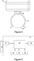
- FIG 3 shows a side elevation of the housing 10 secured to a pipe 12 by connector 14.
- a temperature sensor 16 extends from the case of the housing and is shown contacting the pipe 12 to determine the outer temperature of the pipe 12.
- FIG 4 shows a block diagram of the components comprising the device and their inter connections.
- the housing 10 encloses an electronic control unit (ECU) 40 for monitoring temperatures, time and controlling the device.
- the device is powered by a power supply 42, normally comprising one or more batteries. The selection of batteries will be chosen to provide long life in the environment in which the device is installed.
- Temperature sensor 16 is shown as in contact with pipe 12 to measure the temperature of the pipe. Ambient temperature is measured by temperature sensor 20.
- An alarm unit 46 can include a visible alarm means, typically an LED, or an audible means or driver therefor.
- a wireless connection 48 will also be provided, so enabling the device to periodically transmit data to a remote station and so send an alarm signal when needed. The wireless connection could also receive information or data from a remote station.
- the power could be supplied by a mains network.
- a more sophisticated power supply system is provided in which the power supply comprises a mains power supply connected with one or more batteries.
- Suitable temperature sensors are for example Resol FKP6 PT1000 temperature sensors. Other devices which have been found to work well can be found in the class of PT1000 platinum sensors.
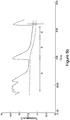
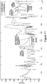
- Figure 5a shows a graph of the temperature measured by each of the sensors over a period of time.
- the graph shows temperature along the Y axis, and time along the X-axis.
- the dashed line is a trace of ambient temperature over a selected measurement period, in this example 2 - 3 hours.
- the solid line shows how the temperature of water in the pipe varies. In region A, a significant flow has been occurring and the water temperature is significantly higher than the ambient temperature. (This can occur in some tropical climates and late in summer when the ground temperature has risen and is consistently (during the course of a day or so) higher than the general air temperature.
- the spikes indicate how the temperature has risen sharply as a significant draw down occurs and show the temperature has begun to fall towards ambient. This draw down could be a flushing of a toilet or water for a basin or sink.
- Figure 5b shows a similar situation to the one in Figure 5a , but in this example, the two temperatures never quite converge, as can be seen in all regions. From this it can be concluded that there is always a flow and there is a leak in the system.
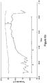
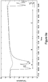
- Figure 6a shows a graph of the temperature measured by each of the sensors over a period of time.
- the graph shows temperature along the Y axis, and time along the X-axis.
- the ambient temperature shown by the dotted line is higher than the incoming water pipe temperature shown by the solid line.
- Such situations can arise in cold or temperate climates where ground temperatures can be and frequently are lower than the ambient air temperature.
- region A tap on off events can be seen as indicated by the spikes in the pipe temperature.
- region B the pipe temperature is rising towards the ambient temperature.
- region C the two temperatures are more or less convergent, and so satisfying the criteria set out that the temperatures must be within narrow bands. This convergent set of temperatures would indicate that there is no leak in the system.
- Figure 6b shows the ambient temperature (shown by the dotted line) is higher than the incoming water pipe temperature shown by the solid line.
- the various spikes in Region A show how the inlet water temperature falls as water is drawn off through the system, and then rises towards ambient, until the next draw off, when it falls again.
- region B there is a prolonged period without a significant draw off of water.
- the two temperatures do not converge closely within the predefined limits, always maintaining a difference of temperature T. Providing this temperature difference (or temperature) is greater than a predetermined value, which can vary according to the geographical and physical location of the device, it can be assumed there is a leak in the system.
- An audible alert - such as a loud speaker will normally be used to provide the alert signal.
- the device will also be provided with a wireless or other communications link.
- the wireless link can be deployed to receive commands and transmit information to a remote station, either continuously on a predetermined period basis.
- any detected flow indicates that a possible leak is present in the system.
- the leak may be due to pipe or pipe joint failure, dripping taps, failed cisterns in toilets or any other condition which would result in continuous water flow in a pressurised plumbing system.
- the device operates for 24 hours a day on a domestic water main. Typically at night there will be no water flowing in the pipes as no taps will be used and appliances such as washing machines will have finished their cycles.
- the device is programmed to monitor and recognise a pattern in temperature change in the detectors. After a period when there are no sudden changes in pipe temperature (due to taps switching on) have stopped or appliances being used the ECU can be programmed to determine if the pipe temperature has not changed rapidly or significantly and compare it to the ambient temperature. It also recognises that the ambient air temperature is stable (within limits) so the device is not being adversely affected by other heat sources (for example being near a radiator or hot water pipe).
- the ECU can be programmed to monitor the changes measured by the temperature detection means of the temperature of the water pipe and the ambient air.
- the water pipe temperature will generally be an exponential approach towards air temperature with a slope within certain limits.
- the asymptotic difference between the pipe and air temperatures will be below a calibrated value, between 0 and 0.5°C, typically between 0 and 0.3°C, but preferably between 0 and 0.1°C. If the asymptotic temperature difference is higher than these values for greater than a predetermined period of time, say an hour or more, then there is usually flow in the pipe indicating a leak.
- the ECU in the detector may determine whether the device is subject to a constant heating or cooling from an external heat source or sink. In this case it may alert the user that it is unable to determine if a flow condition is present.
- the device may detect that its sensors are giving invalid values due to an error or component failure and alert a user to the fault.
- the device may alert a user by one of many different means typical of such domestic alarms. For example it may use an audible alert. Alternatively, or additionally, it may also include a light or a display. To avoid waking a user at night, it may wait until it next detects flow (because a user has woken up) before issuing an alert.
- the device may also issue alerts and other information via a remote telemetry system.
- a remote telemetry system This could be one of any such technologies known in the art.
- a cellular phone modem an internet connection, a home automation protocol (e.g. Z Wave), a landline phone modem, an acoustic modem or any other such transmission mechanism.
- the device detects the sudden changes in pipe temperature relative to air temperature which are characteristic of taps turning on or toilet flushes. It can be calibrated to estimate frequency and quantity of water usage. Dips (or peaks) in the pipe temperature show water usage. Counting short dips shows the frequency of water usage for low use items (hand washing, toilet flushing). The height of the dips give an estimate of the incoming mains water temperature.
- the pipe temp is approximately the same as the input water temperature for an extended period of time, we can assume we have constant flow over that time period. This indicates either shower, bath filling or other extended use such as irrigating a lawn.
- the ECU restarts the determination of the predetermined period of time if the difference between the ambient and pipe temperatures suddenly changes to be greater than the predetermined value.
- the ECU can be programmed to determine that a flow of water has occurred and so restart its monitoring process.
- the ECU determines if the temperature difference between the ambient and pipe sensors is tending to or approximating to an exponential approach to 0 and if so indicating there is no flow in the pipe system. If the two temperatures do not converge exponentially after a period of say an hour, the device can be programmed to generate an alarm signal.
- the device can be programmed to note the absence of water usage over a period of time. This information may then be used to check on the presence and activity of a person in the home. For example if an elderly or vulnerable person has not used water for a predetermined period, such as a day, it may indicate that they have a problem and a carer can be alerted.
- the device can be programmed to rank a water leak rate according to size of the temperature difference (assuming it has reached a constant or substantially constant difference for a period of time,) thus providing an indication of the severity of the leak. If the pipe temperature stays at close to the estimated incoming water temperature (using the dip height method above), then the leak is a reasonably high flow rate. If it is within 0.5°C or so of the air temperature, it is typically a dripping leak. Temperatures in the middle indicate a medium flow leak.
- the device may have a 'holiday' mode that can be set by a user who knows that no water flow should be expected for e.g. 72 hours or 14 days or however long a user is absent. If any water flow is detected during that period, an alert would then be triggered.
- the device may connect to a service which could alert the user (e.g. by text, email or smartphone app) of the presence of leaks automatically, or it could send the alert directly to a maintenance company.
- the service may also alert a service provider or a plumber who could then check the leak.
- the device could also contact for example a neighbour who may check on a property.
- Figure 7 shows a possible additional feature in which the device is connected to and controls a powered shut-off valve.
- the device may then, depending upon the estimated severity of the leak, shut off the water supply in response to a leak. It could also shut-off the water when the device is in holiday mode, or only if any flow is detected when it is holiday mode.
- Fig 7 shows a device 10 monitored by the ECU 40 and fitted to the pipe 12 . If a leak is detected or there is flow for more than a predetermined period of time, then the controller can shut off the supply in pipe 12 using the valve 50.
- the user may also be able to shut off the water for example using a remote switch, or another interface such as a smart phone app.
- the ECU may be configured to monitor flow and signal an alarm if there is no flow for a given period of time.
- the alarm may sound if there is no flow for more than 36 hours.
- the alarm signal may be sent if there is no flow detected for periods between 18 and 24 hours.
- This embodiment could be particularly useful as an aid to monitor people living in sheltered or supported accommodation where lack of water flow for an extended period could be an indication the person or persons are in need of help.
- a balance needs to be struck between having a period that is not too long so that the person is not left for too long if help is needed and a period which is too short that it leads to false alarms.
- An alarm signal can be generated if the predetermined conditions for flow (or lack of flow) are met.
- the alarm could be an audible alarm generated by the audible signal generating means on the device itself. Alternatively or additionally, a visible alarm signal could be generated.
- the wireless transmitter can also be programmed to transmit additional information from time to time.
- Such information could conveniently include information about flow rates and periods of zero flow, information about the state and condition of the batteries to provide low battery warnings, other error messages to indicate sensor errors or the like.
- the power supply is a battery or set of batteries selected to provide long maintenance free life in an environment in which the device operates.
- it could advantageously be connected to a mains power supply.
- the power supply comprises a mains power supply connected to a battery pack up system to provide power in the event of mains failure.
- the ECU or at least the pipe temperature sensor, may be connected to an indoor pipe, e.g., a water pipe preferably close to where the pipe enters a building (for example through the floor).
- the pipe may be close to additional heat sources, e.g., other plumbing for example carrying hot flowing water such as for a central heating system.
- a high heat capacity local object e.g. a concrete block and/or other plumbing as above, may result in a different temperature versus time progression of the pipe temperature relative to the ambient pressure during a no flow period. This may lead to the pipe temperature crossing the ambient, e.g., air, temperature as mentioned above, and may restrict the ability to confirm presence or absence of a leak.
- no alarm e.g., visual and/or audible notification or alert
- the alarm may be disabled regardless of whether it is detected that the air and pipe temperatures are converging (see leak detection methods below based on time gradient of pipe temperature).
- An embodiment may be configured to detect a crossing point and thus to conclude that the mass lag effect is occurring, and to enable or disable a leak alarm accordingly, for example for a predetermined period of time until monitoring for a leak may restart.
- a leak condition is determined using a threshold, for example at least based on a temperature difference between the pipe and ambient relative to a predetermined threshold for a predetermined period as described above and/or based on a temperature gradient and predetermined threshold as described below (see equations 4a, 4b, 6a, 6b below), it may be advantageous to vary such a threshold(s) for example according to the time of year. Regardless of whether or not the flow detection system, e.g., ECU thereof, is able to track the time of year for example by means of an internal electronic calendar, the threshold may be varied based on a starting difference between the pipe and ambient temperatures.
- the starting temperature difference may be the difference in readings of the two temperature sensors at the start of the predetermined period used to monitor for a leak.
- the start of the predetermined period may be identified when it is detected that the difference between the temperatures suddenly changes at a rate above a pre-determined value and/or may be the last detected time point where the temperature versus time gradient of the pipe temperature reverses sign such that the pipe temperature tends towards the ambient temperature.
- a lower threshold may be applicable. For example, if the starting temperature is 4°C then a predetermined threshold may have a value of 0.3°C, or if the starting temperature difference is 0.5°C then the threshold may be 0.1°C.
- a leak condition is determined using a threshold, for example at least based on a temperature difference between the pipe and ambient relative to a predetermined threshold for a predetermined period as described above and/or based on a temperature gradient and predetermined threshold as described below (see equations 4a, 4b, 6a, 6b below), the embodiment may further be configured to perform a offset procedure similar to a calibration. This may be advantageous in view of the potential scenario that the pipe temperature does not approach the ambient temperature at least within the predetermined period because of the thermal lag effect of a local object having significant thermal mass capacity.
- the embodiment may determine if there is any residual temperature difference between the pipe and ambient and, if there is, adjust, e.g., increase or decrease, the pre-determined threshold accordingly. Thus, a form of calibration procedure or adjustment may be performed.
- the embodiment may alert the user, e.g., by a visual and/or audible signal or notification, that the embodiment is unable to detect a leak and/or that the attachment to the pipe (e.g., at least the pipe temperature sensor) needs to be moved to a different position on the pipe, e.g., away from the ground.
- a visual and/or audible signal or notification e.g., by a visual and/or audible signal or notification, that the embodiment is unable to detect a leak and/or that the attachment to the pipe (e.g., at least the pipe temperature sensor) needs to be moved to a different position on the pipe, e.g., away from the ground.
- a calibration procedure may be carried out for example in a factory before delivery to a user, to reduce any effects due to mismatching of the temperature sensors.
- An offset to be applied to any determined temperature difference on which a leak status may be detected may be determined by placing the unit in a thermally insulated environment, e.g., insulated box, and waiting for a relatively long duration e.g. six hours, before measuring any temperature difference between the sensor readings and adjusting the offset accordingly. This may be performed by a test mode of the unit when the unit is first powered up.
- An embodiment may be configured to detect when the unit is mounted on a pipe such that operation for monitoring for any leak can be started.
- the unit may be configured to wait until a sudden change in pipe temperature relative to the ambient temperature is detected, preferably repeatedly such as at least three times in 24 hours. The unit may then effectively know that it is in use, i.e. no longer separate from a pipe to be monitored.
- Such a feature may give confidence for example to an insurer that any readings or notifications arising from the unit relating to leak detection have resulted from events occurring while the unit was fitted to a pipe.
- the start of leak detection operation may be indicated by communicating this to a remotely located control entity and/or may be recorded internally within the unit, preferably recording the date at which the unit was mounted onto the pipe, or incrementing an internal timer so the total time that the device has been fitted to a pipe is known.
- An embodiment may have a re-set button to allow a user to deactivate an alarm (e.g., visual and/or audible notification or alert) that has been activated in the event of the system/device indicating a leak.
- the system e.g., ECU
- the system is configured to store internally and/or communicate externally that the alarm has been re-set (e.g., including a time of the re-set), and may further store and/or communicate when the alarm has been re-set (e.g., including a time of the re-set). This may allow determination for example by an insurer of when the alarm has been re-set but no call out for attending to a potential leak has been initiated.
- the re-setting of the alarm may be communicated, e.g., wirelessly, to a remote entity.
- a preferred embodiment does not provide an alarm, e.g. notification to the user and/or an audible and/or visual indication by the unit, every time a potential leak is detected.
- Such an alarm may be provided only when a potential leak detection occurs repeatedly on each of a pre-determined number of periods when no flow would be expected in the absence of a leak, e.g. three night time such periods.
- a temperature pattern is detected having transition(s) corresponding to at least one leak-no leak transition during each of a predetermined number of such periods then no alarm may be generated.
- Such a pattern may merely indicate that a user has a tendency to sometimes leave a tap dripping and not fully off and later to turn it off fully, for example.
- no alarm is generated until at least seven night-time periods (or other periods of no flow expectation during a respective 24 hour periods) have occurred.
- An embodiment may be configured to detect when the pipe temperature stays substantially constant at a temperature that differs significantly by a predetermined amount at least from the ambient temperature.
- the pipe temperature may have previously varied according to fluid (e.g. water) usage but then remain at the substantially constant temperature without beginning any rise towards the ambient temperature.
- the substantially constant temperature may be detected as corresponding to a water temperature estimated based on the preceding variations according to usage.
- the pipe temperature remains at the constant temperature for a predetermined period, preferably longer than the longest period of usage expected for full flow such as when a user is washing a car (e.g. longer than 1 hour), this may indicate a burst pipe condition.
- the detection of the substantially constant temperature for the pre-determined period results in the unit immediately issuing an alarm (e.g., visual and/or audible notification or alert). It is preferable in this case that the generation of a leak alarm is not disabled even for verification over more than one 24 hour period. In other words, preferably no verification is to be performed before issuing an alarm in the case of a potential burst pipe detection.
- An embodiment may be configured to detect when a pre-determined number of, e.g., 24 hour, periods have passed with no flow, for example encompassing seven nights. Such no flow may be detected by determining that the pipe temperature tracks the ambient temperature throughout the predetermined number of such periods. If such an extended no flow period has occurred and the embodiment subsequently detects a sudden change in pipe temperature, for example indicated by a rate of change of pipe temperature greater than a pre-determined amount or a change in magnitude of pipe temperature greater than a pre-determined amount preferably over a pre-determined minimum period such as 60 minutes, an alarm (e.g., visual and/or audible notification or alert) may be generated due to the risk of the change indicating a burst pipe. Preferably no delay e.g. due to verification, is allowed before such an alarm is issued.
- a pre-determined number of, e.g., 24 hour, periods may be detected by determining that the pipe temperature tracks the ambient temperature throughout the predetermined number of such periods. If such an extended no flow period has occurred
- a property may have one or more valves that allow for automatic re-filling of tanks.
- a valve is for example a Torbeck valve for re-filling the tank or cistern of a toilet.
- the valve may have hysteresis built in such that it allows flow intermittently, e.g. periodically, for example every few hours.
- An embodiment may be configured to detect a repetitive, e.g., periodic, flow pattern corresponding to such a valve. Such a pattern may be detected from corresponding changes of pipe temperature.
- the embodiment may be programmed to filter out such changes from the pipe temperature profile to be monitored for leak detection relative to the ambient temperature. In this way, false leak alarms may be reduced or prevented.
- An embodiment may output a minimum of data points from temperature profiles of the air and pipe and send these to a remote entity for determination of a leak/no leak status.
- data points may comprise the ambient temperature, pipe temperature, starting temperature and/or temperature-time gradient(s) of the ambient and/or pipe temperature profiles at the time point when the flow was last detected, e.g. water was last used.
- Such data points may be transmitted, e.g. wirelessly, to a remote control unit that decides if a leak has occurred based on those data points. This may be advantageous where the remote system decides what should be an appropriate predetermined threshold of temperature difference, for example depending on weather patterns/forecasts.
- the remote entity may adjust such a threshold on the fly for example in case of a heatwave where the ambient temperature is of the order of e.g. 30°C and the pipe temperature is therefore not able to catch up during the predetermined period.
- the remote system may be able to ensure that all devices are disabled from providing any leak alarm and/or ensure that any such alarm is ignored.
- Such remote control of the alarm process may be advantageous where sufficient data on preceding weather conditions is not able to be programmed into a leak detection unit mounted on a pipe.
- the system has some flexibility.
- a leak detection unit may have two modes of operation. In a first mode where radio communications are possible, the remote system may decide based on data points from the leak detection unit when an alarm is to be generated. In another mode, the unit detects that it is out of radio communication and is then configured to make decisions on alarms internally.
- An embodiment of the leak detection unit may have an indicator for indicating to the user whether or not the unit is able to perform radio communications with the remote entity. Where the unit is not in radio communications, it may be configured to provide notification to the user, e.g. to the user's mobile phone, to inform that the unit is operating in the independent, isolated mode.
- data may be sent to a remote unit wirelessly, e.g., using sigfox (RTM) (this may be advantageous where there are bandwidth constraints).
- RTM sigfox
- a unit that is local to, eg., attached to, the pipe may look for smooth regions where we can check for leaks (for example, it may look to (re-)start a predetermined period each time a water usage/flow is detected), then a predetermined threshold for leak detection may be adjusted at the remote unit to allow for temperature variations, desired sensitivity of the detectors, and/or to classify the leak according to severity.
- Data that may be sent using, e.g. sigfox (RTM), may comprise for example: message type; message count; indication that ambient and pipe temperatures have crossed; pipe temperature sample(s), ambient temperature sample(s); indicator of time interval between each pipe temperature sample; and/or battery voltage.
- RTM sigfox
- the ambient/air and pipe temperatures may be sent to the remote unit at every sample point. These may be batched and sent as a group to save battery power (e.g. send the last 10 samples every 1000 seconds).
- the leak detection algorithm may then be run remotely (permitting updates to be applied without needing to reprogram the detectors in the field).
- the predetermined period during which an embodiment monitors for a leak may have a predetermined duration, e.g. 2.7 hours, beginning at a starting time.
- the starting time may be determined by detecting a peak in d 2 T/dt 2 , taking into account the sign of this second differential (the term 'differential' being used interchangeably with 'derivative' throughout this specification, for example the second order derivative d 2 T/dt 2 being referable to as a second derivative/differential of temperature with respect to time).
- Such a peak may be interpreted as indicating a water usage/flow and may thus be used to trigger the start of a new predetermined period, e.g., to re-start an existing monitoring period.
- the second order differential When the second order differential is negative and the pipe temperature is greater than the ambient/air temperature, this may indicate the start of the predetermined period.
- the second order differential When the second order differential is positive and the pipe temperature is less than the air temperature, this may similarly start a predetermined period.
- One method of leak detection involves using a determination of temperature difference between pipe and ambient air sensors and determining if the temperature difference is below a pre-determined threshold for a predetermined period, as described elsewhere in this specification.
- a pre-determined threshold for a predetermined period, as described elsewhere in this specification.
- an embodiment may determine a leak/no leak state based on whether or not the pipe temperature and ambient temperature tend to converge (as opposed to, e.g., 'tracking', i.e., generally staying parallel with a constant or zero offset).
- the pipe and ambient air temperatures may tend to gradually converge.
- the pipe temperature may tend to a constant temperature without returning to or at least converging towards the ambient temperature; this may even involve the pipe temperature crossing the ambient temperature.
- the pipe temperature may gradually drop or rise depending on the environment so that the temperature difference between the ambient and pipe temperature sensors generally reduces.
- Such monitoring may allow early detection of a leak without awaiting detection of a sufficiently low and/or constant temperature difference between the sensors, e.g., without waiting to see if the pipe and ambient temperatures track and/or become closer than a threshold difference apart.
- a preferred embodiment additionally to the monitoring of the temperature difference relative to a threshold, may monitor whether or not the pipe temperature tends to converge towards the ambient temperature, when there has been no other water usage for a length of time (for example 5 minutes). Detecting such a lack of water usage may be done by monitoring the second differential of the pipe temperature relative to time (i.e., d 2 T p /dt 2 ), and waiting for it to be below a certain threshold, indicating no sudden changes in temperature and hence no changes in flow due to taps switching off and on or other intermittent usage.
- an embodiment may monitor the pipe and air temperatures based for example on the equations below.
- h1 may be considered a (generally constant) transfer coefficient between the pipe and the ambient (e.g. air), and h2 may be considered to be a flow-dependent (thus, may be non-constant) transfer coefficient between the pipe and mains water supply.
- h2 may be strongly dependent upon the rate of flow of the water in the pipe, q. If q is zero (no leak), then h2 will be very close to zero. If q is non zero, then h2 may start to affect, and/or have a greater effect on, dTp/dt.
- Tp the coefficient of heat transfer between the water and the pipe, h2 may be larger relative to h1.
- Tp will generally tend towards Tw.
- the rate of change of Tp, dTp/dt may be small, even if there is a still a relatively large difference between the air temperature and the pipe temperature (Ta-Tp). This may be indicative of flow in the pipe and presence of a leak.
- the gradient in the pipe temperature over time is small relative to the difference between the pipe and the ambient/air temperatures.
- the pipe temperature may then be not tending towards the ambient/air temperature in a way which would be expected under a no leak condition, i.e., there may be an additional heat source or sink being applied to the pipe, potentially indicating the presence of flow in the pipe and thus a leak.
- THRESH is a value that is preferably close to zero but sufficient to allow for variations due to noise and/or water temperature changes.
- THRESH THRESH
- dTp / dt / Tp ⁇ Ta > THRESH
- this may be interpreted as indicating that there is not a leak.
- Example values of THRESH may be, e.g., 0.001, 0.005, 0.01, 0.1 or 1.
- exponential function(s) may be fitted (e.g., finding a best fit for example by means of a least squares fitting method) to the Tp and/or Ta samples over a region in which there has been no previously calculated water usage (this may have been indicated by other means). The exponential function(s) may then be used to calculate a value indicative of dTp/dt by analytical differentiation of the fitted exponential.
- Each fitted exponential function for the pipe and air temperature may be of the form a + bt + ce dt where a, b, c and/or d are generally taken to be constants and t is an indicator of time.
- analytical differentiation of the function may calculate the value indicative of dTp/dt by calculating b + cde ct .
- an equation above e.g., (3), (4a) and/or (4b) may allow an early and/or fast response to a leak condition.
- leak detection based on a ratio such as in equation (4a) and/or (4b) may be combined with an above described detection method based on detecting when a temperature difference is below/ not below a predetermined threshold for a predetermined period. For example, they may run in parallel to provide redundancy and/or to improve robustness. If either algorithm predicted a leak a number (1 or more) of times then a leak could be reported for example by outputting an alarm.
- dT p /dt ⁇ Ah Mcp T p ⁇ T a
- Ah is a constant relating to a contact area between the pipe and fluid (e.g., water)
- Mcp is a constant relating to a mass of the pipe and water mass, i.e., Ah/Mcp may be regarded as a heat transfer coefficient b.
- F' may be considered to represent a leak, expressed here as an effective reduction in ambient temperature. Thus, determining whether F is large or small may indicate the presence or absence of a leak.
- Example values of THRESH may be, e.g., 0.001, 0.005, 0.01, 0.1 or 1.
- a leak detector for detecting a leak in a water supply system comprising a pipe may have a first temperature sensor detecting ambient temperature, a second temperature sensor configured to be mounted adjacent or in thermal contact with a pipe of the pipe system, and a processing means configured to determine a temperature difference between the first and second temperature sensors, wherein the processing means is configured to indicate the presence of a leak if a monitored variable is above a predetermined threshold for a predetermined period, wherein the monitored variable is the sum of an indicator of time gradient of the sensed pipe temperature and a multiple of the temperature difference, where the multiple represents a constant heat transfer coefficient.
- the leak detection method based on such a sum may be combined with either or both of the two methods based on the temperature difference relative to a predetermined threshold and on h1'. Furthermore, optional features provided for either of those two methods, for example with regarding to identifying the starting point for the predetermined period, etc., may be applied for this sum-based method similarly.
- leak detection in line with equation (6a) and/or (6b) may be combined with an above described detection method based on detecting when a temperature difference is below/ not below a predetermined threshold for a predetermined period and/or with a detection method based on a ratio as in equation (4a) and/or (4b).
- any two or more of these methods may run in parallel to provide redundancy and/or to improve robustness. If either algorithm predicted a leak a number (1 or more) of times then a leak could be reported for example by outputting an alarm.
- the embodiments described herein are implemented indoors, i.e., are attached to a pipe within a property in order to detect leaks. This may be advantageous depending on geographic location, since an outdoor location may require some thermal insulation to prevent the pipe freezing. Such insulation may interfere with monitoring the ambient temperature, depending on the arrangement of sensors.
- Fig. 10 shows further example temperature-time traces of pipe temperature Tp and ambient temperature Ta, including monitoring periods for 'no flow' and 'flow' instances.
- Fig. 11 shows further example temperature-time traces of pipe temperature Tp and ambient temperature Ta.
- a maximum ambient / air temperature may be used for a starting temperature difference to trigger a monitoring period.
- the ambient / air temperature used for the starting difference may be the temperature of the ambient / air at the instant that the pipe temperature curvature is at a maximum.
- Fig. 12 shows an example fluid flow detector system 10a, for monitoring a pipe 12a of a water supply system 100.
- the water supply system may further comprise a stopcock 150, a valve 140 such as a Torbeck valve, and/or a powered shut-off valve 130 which may be controlled for example by the processing means (preferably comprising one or more processors), e.g., ECU 40a.
- the fluid flow detector system may be a self-contained device for attaching to the pipe 12a, or may comprise a system of couple devices, e.g., the pipe temperature sensor 16a and/or ambient temperature sensor may be provided externally to a device comprising the processing means 40a, e.g., may be coupled by a wire(s) or wirelessly to such a device.
- the power supply 42a may be coupled to a mains network 120 and/or may comprise a battery(s).
- the alarm generator 46a is shown in the fluid flow detector system, e.g., in a device housing at least the processing means, however such an alarm generator may additionally or alternatively be provided at a remote entity 110.
- the alarm generator 46a may send an alarm preferably, wirelessly, to a user 160 and/or to or via a relaying means 48a and/or a remote entity.
- the fluid flow detector system e.g., a device comprising at least the processing means, may comprise a relaying means, e.g., a communication interface comprising a transmitter and/or receiver, preferably wireless, for communication with a remote entity 110 (e.g., remote alarm signal receiving station).
- Fig. 13 shows an example computing device or system on which at least the processing means, e.g., electronic control unit, of an embodiment may be implemented.
- remote entity e.g., remote alarm signal receiving station
- the computing device/system of Fig. 13 comprises a bus, at least one processor, at least one communication port (e.g., RS232, Ethernet, USB, etc.), and/or memory, all generally coupled by a bus (e.g., PCI, SCSI).
- a bus e.g., PCI, SCSI
- the memory may comprise non-volatile memory such as read only memory (ROM) or a hard disk and/or volatile memory such as random access memory (RAM, e.g., SRAM or DRAM), cache (generally RAM) and/or removable memory (e.g., EEPROM or flash memory).
- the processor may be any known processor, e.g., an Intel (registered trademark) or ARM (registered trademark) processor.
- a user interface e.g., display screen and/or keyboard may be provided.
- the processor 24a may be an ARM (RTM) device or a similar processor produced by another manufacturer such as Intel (RTM).
Description
- The present invention generally relates to a water leak detector for detecting fluid flow in a pipe system. The disclosure relates to a device for detecting flow in pipes, in particular a fluid flow detector, a leak detector and a water supply system comprising such a leak detector.
- Being able to detect fluid flow in a pipe has many useful applications. A key one is detecting the presence of leaks in a pipe system. Detecting flow in a system when all taps and valves are closed will usually indicate the presence of a leak in the system being monitored.
- Pipe systems can be used to transmit a complete range of fluids from air and other gasses, including combustible gasses to liquids. The liquids can be water, oils or any other liquid. In any pipe system it is important to know if there is leakage in the pipe system.
- Many technologies exist for measuring flow. Many involve a mechanical device in the flow e.g. an impellor or nutating disc. In order to fit these, the system must be drained and the device inserted in the pipe. This can be inconvenient. Additionally, there is a risk of leak in the area where the measurement device has been inserted.
- Non-invasive measuring techniques also exist - e.g. ultrasound and thermal mass flow measurement. However, ultrasound systems tend to be relatively expensive and do not detect flow velocities less than around 1cm/sec. Thermal mass flow metering requires the fluid to be heated by an element which requires too much power for a system to be battery powered for an extended period of time.
- It is an object of embodiments of the present invention to provide a preferably non-invasive method of detecting fluid flow in a pipe system.
- It is also desirable in embodiments to be able to monitor flow rates - or lack thereof remotely from a central control unit or monitoring station.
- Embodiments of the present invention provide a system, device and a method for non-invasively detecting fluid flow in a pipe. Advantageously, the method and system or device may be a low powered method suitable for a battery powered monitor.
- For use in understanding the present invention, the following disclosures are referred to:
-
US2010/206090 A1 (Stack); -
EP2840362 (Kamstrup); -
WO2015/097407 A1 (GRDF); -
US2012/206272 A1 (Borlee) discloses a mechanical fluid meter, for liquid or gas. The meter comprises an analysis means for establishing the temperature difference between the fluid temperature and the ambient temperature and for taking into account the fluid flow rate value supplied by the meter, said analysis means being programmed so as to display and/or transmit information indicating a meter blockage when the temperature difference is higher than a predetermined limit and the flow rate value supplied by the meter is zero; -
US9146172 B2 -
US7308824 B2 (Trescott); - http://www.aircon.panasonic.eu/GB_en/happening/4679/ found to be available at 24.11.15;
- http://www.neptuneoceanographics.com/thermal-leak-detection.php found to be available at 24.11.15;
-
WO01/25743 A1 Fig. 2 relates to an example wherein a time span measurement device runs as long as the temperature difference is over 0, and the alarm will start when the time span exceeds 24 hours.Fig. 3 relates to an example wherein a time span measurement device runs as long as the temperature difference is between 0, and 5 C and the alarm will start when the time span exceeds 3 hours; and -
WO2011107101 A1 (Klokker) relates to an apparatus for leak detection in pressurised tubes for flowing substances, which apparatus comprises at least one detector connected to the outside of a tube, which detector measures the actual temperature. An embodiment has a processor that repeats the storing of a new temperature dependent data set in a memory after a first defined time period, performs an analysis of the temperature profile by analysing the change in temperature backwards in a second time period, and performs a search in the temperature profile for at least one rapid change of the surface temperature of the tube. - The present invention is a water leak detector for detecting fluid flow in a pipe system, wherein the fluid comprises water, the detector having a first temperature sensor configured to detect ambient temperature, a second temperature sensor to detect pipe temperature configured to be coupled in thermal contact with a pipe of a said pipe system, a processing means configured to determine a temperature difference value between the first and second temperature sensors and to detect a leak based on the temperature difference value, said leak detection comprising, if the temperature difference value is above a predetermined threshold value for a time period having predetermined duration, a determination that fluid is flowing in the pipe system, wherein the processing means is configured to restart the determination of the time period if the pipe temperature changes at a rate above a predetermined value.
- Preferred embodiments are defined by the dependent claims.
- Embodiments will now be described with reference to the accompanying drawings in which:
-
FIG 1 shows an example of a flow detector device attached to a pipe. -
FIG 2 shows a top view of the detector device. -
FIG 3 shows a side elevation indicating how contact is made with the pipe. -
FIG 4 shows a block diagram of the inter-connection of the components. -
FIG 5a is a graph showing the temperature of the pipe and the ambient air over a 5 hour test period with no flow in the pipe where the water is warmer than ambient. -
FIG 5b is a graph showing the temperature of the pipe and the ambient air over a 5 hour test period with a small amount of flow in the pipe where the water is warmer than ambient. -
FIG 6a is a graph showing the temperature of the pipe and the ambient air over a 5 hour test period with no flow in the pipe where the water is warmer than ambient. -
FIG 6b is a graph showing the temperature of the pipe and the ambient air over a 5 hour test period with a small amount of flow in the pipe where the water is cooler than ambient. -
Fig 7 is the block diagram of the system where a shut off valve is used to shut off the water supply in the event of a leak being detected. -
Fig. 8a is a graph showing the temperature of the pipe and the ambient air over a test period with no flow in the pipe where the water is warmer than ambient. -
Fig. 8b is a graph showing the temperature of the pipe and the ambient air over a test period with a small amount of flow in the pipe where the water is warmer than ambient. -
Fig. 9a is a graph showing the temperature of the pipe and the ambient air over a test period with no flow in the pipe where the water is warmer than ambient. -
Fig. 9b is a graph showing the temperature of the pipe and the ambient air over a test period with a small amount of flow in the pipe where the water is cooler than ambient. -
Figs. 10 and11 show further examples of temperature-time traces. -
Fig. 12 shows an example implementation of a fluid flow detector system/device. -
Fig. 13 shows an example computing device or system on which at least the processing means, e.g., electronic control unit, of an embodiment may be implemented. - Embodiments which do not comprise all the features of
independent claim 1, in particular those which do not consider the rate of pipe temperature changes, are not part of the present invention. - We firstly describe a fluid flow detector. An embodiment of the fluid flow detector is for detecting fluid flow in a pipe system, the detector having a first temperature sensor to detect ambient temperature, a second temperature sensor configured to be mounted adjacent or in thermal contact with a pipe of the pipe system, a processing means configured to determine a temperature difference between the first and second temperature sensors and if the temperature difference is below a predetermined threshold for a predetermined period, to determine that no fluid if flowing in the pipe system. The processing means may comprise one or more processors.
- The inventor has determined that in a pipe system, if there is no flow of fluid in the pipe system, the temperature of the fluid in the pipe, sufficiently distant from any other sources of heating or cooling, will approach ambient temperature over a period of time. By determining the ambient temperature of air or other medium around the pipe system and the temperature of the fluid in the system, it is possible to determine if fluid is flowing in the pipe system. If the temperature of the fluid in the pipe system is monitored over a period and compared to ambient temperature and the two values approach each other and maintain a predetermined difference or less for a predetermined time, a no flow condition can be determined to exist. If the temperature differences remain outside a predetermined set of parameters, it can be assumed there is a flow in the pipe system.
- If on the other hand, the difference in temperatures between the "ambient" and the fluid in the pipe is greater than a predetermined value for a predetermined period, there can be assumed to be a flow condition.
- The fluid flow detector may comprise a single device or a system having more than one device. Thus, references to a device throughout this specification are interchangeable with references to a system.
- There may be provided the device in which a zero flow condition is determined if the temperature difference between the temperature sensors is less than about 1.0 deg C (degrees Centigrade) for at least one hour. (The fluid flow detector being referred to as a device; as noted the detector may be a system comprising more than one device).
- There may further be provided the device in which a zero flow condition is determined if the temperature difference between the temperature sensors is less than about 0.5 deg C and preferably (i.e., optionally) less than 0.3 deg C for at least one hour.
- There may further be provided the device in which a zero flow condition is determined if the temperature difference between the temperature sensors is less than 0.1 deg C for at least one hour.
- The determination of a zero flow condition is particularly useful in a number of environments or installations such as domestic, office or industrial water systems, reserve or standby fluid pipe systems such as might be employed in emergency or backup systems.
- In such systems there are periods when it can be anticipated there will not be any fluid flow. This lack of flow will provide sufficient time for the fluid temperature to converge to the ambient temperature. Such periods can be, for example, overnight or at weekends.
- There may further be provided the comprising means in which in an alarm signal is generated if the temperature differences fall outside predetermined parameters for a predetermined time. Such a means may be implemented in various ways, for example using an audible and/or visual indication and/or communication to a remote entity, and may be described as an alarm generator.
- In one example, ideally suited to such a system is a domestic or office water supply system. In these systems, water is supplied from a mains system normally entering a building from under the ground. In normal circumstances, when fluid is flowing, there will be a temperature difference between the incoming fluid and the temperature of the air surrounding the pipe several centimetres from the ground. By monitoring these two temperatures over a period of time their convergence can be monitored and providing the difference in the determined temperatures are less than a predetermined value for a predetermined period, a leak free condition can be considered to be achieved. However, if there is a continuing small temperature difference, particularly during a time when no flow would be expected, a leak condition can be considered to arise and an alarm or alert can be raised.
- Preferably, the temperature sensor used to detect the water temperature is in good thermal contact with the pipe. Alternatively, if the sensor is in close proximity to the pipe it may be possible to measure the temperature of the fluid in the pipe with sufficient accuracy to enable a control and monitoring unit to detect a temperature difference.
- Various mechanisms can be envisaged to ensure the pipe sensor is in good contact with the pipe. These could include biasing the sensor so that it is biased into contact with the pipe by spring or other biasing means. Alternatively, and more advantageously from the device construction point of view, a spring clip can be used to ensure the device is securely clipped to the pipe and can be arranged to ensure the temperature sensor is in good contact with the pipe. Alternatively a strap or other tie mechanism could pass around the pipe, securing the sensor to the pipe. This could apply a pressure maintaining the thermal contact with the pipe.
- The device is provided with an Electronic Control Unit (ECU) or a microcontroller which can be configured to have one of many arrangements. It can be provided with a large number of pre-programmed calibrations and measure temperatures and signal alarms according to a set of pre-programmed instructions.
- Alternatively, each device can be provided with an ECU which is capable of calibrating the measurements obtained from the two temperature sensors and be further calibrated according to the type and details of the installation. This latter is advantageous in that it should ensure greater accuracy and reduce the number of false alarms.
- The ECU needs to be capable of monitoring the outputs provided by each of the temperature sensors and comparing them over an extended period of time to determine any differences and whether the differences fall within predetermined thresholds. If the appropriate criteria are satisfied an alarm signal can be generated.
- In a domestic or office environment, the temperature of the incoming cold water in a water supply varies through the year, but is typically different to room temperature due to the water being chilled or heated by the earth surrounding the subterranean supply pipes. Water flowing through the pipes will then tend to chill the pipes (or warm them, depending on the climate or time of year) to a measurable degree, even at very low flow rates (down to 5ml/min). This phenomenon can be used to detect whether or not water is flowing in the pipe.
- By measuring the temperature difference for an extended period of time, the presence (or absence) of flow can be detected. For a typical domestic dwelling, periods of zero flow (e.g. at night) can be expected. If flow is detected, it probably indicates the presence of a water leak or a dripping tap or valve in a toilet. A user can then be alerted to the presence of the leak so they can fix the problem, reducing water damage to a property and reducing water wastage.
- It is also now well known that in modern domestic environments it is increasingly common to operate water consuming domestic appliances, such as washing machines or dishwashing machines, at night in order to benefit from cheaper energy tariffs available. Operation of such appliances will result in a rapid and significant flow of water at periods during the operation cycle. This rapid flow will cause a sudden change in temperature of the water in the pipe. The monitoring system may therefore be provided with means, generally comprising a processor and/or at least one temperature sensor, to detect the sudden and significant temperature change and an ECU may be programmed to ignore or discount such sudden surges and not produce an alarm condition.
- In such circumstances the monitoring system may be triggered to reset itself so it again waits for the temperatures to converge, and begin monitoring afresh.
- There is further provided a leak detector comprising the fluid flow detector, wherein the leak detector is configured to indicate a leak detection if the temperature difference is not below a predetermined threshold for the predetermined period, wherein the leak detector is configured to indicate a leak of the pipe system preferably wherein the pipe system is of a domestic building or of an office water supply system.
- Advantageously, the leak detector is for detecting a leak in a domestic building or office water supply system comprising a pipe, the leak detector having a first temperature sensor detecting ambient temperature, a second temperature sensor configured to be mounted adjacent or in thermal contact with a pipe of the pipe system, and a processor configured to determine a temperature difference between the first and second temperature sensors, wherein the processing means is configured to determine a heat transfer indicator based on a ratio of an indicator of time gradient of the sensed pipe temperature relative to the determined temperature difference between the first and second temperature sensors, wherein said temperature of the pipe is sensed by the second temperature sensor, the processing means further configured to determine if the heat transfer indicator is below a predetermined threshold for a predetermined period and to: if the heat transfer indicator is below a predetermined threshold for a predetermined period, indicate a leak detection; and/or if the heat transfer indicator is not below a predetermined threshold for a predetermined period, indicate absence of a leak detection.
- The processing means may be configured to determine a best fit exponential function to the sensed temperature of the pipe and determine said indicator of time gradient of temperature of the pipe on the basis of said exponential function.
- The leak detector implements the above leak detection based on if the temperature difference is not below a predetermined threshold for the predetermined period and further implements the above leak detection based on the ratio of an indicator of time gradient of the sensed pipe temperature relative to the determined temperature difference. The two methods - the first based on if the temperature difference is not below a predetermined threshold for the predetermined period, the second based on the ratio of an indicator of time gradient of the sensed pipe temperature relative to the determined temperature difference - are combined, wherein the determination of the time period is restarted if the pipe temperature changes at a rate above a predetermined value.
- The processing means may be configured to monitor an indicator of a second order derivative with respect to time of the pipe temperature sensed by the second temperature sensor and to detect if said second order derivative indicator has been below a predetermined value for a predetermined time duration, wherein the leak detector is configured to perform, in response to a said detection that said second order derivative indicator has been below a predetermined value for a predetermined time duration, said determining if the temperature difference is below a predetermined threshold for a predetermined period or said determining if the heat transfer indicator is below a predetermined threshold for a predetermined period. This may be advantageous, for example to allow a lack of water usage for a period to be established before allowing leak monitoring to begin.
- The leak detector may be configured to detect when an indicator of a second order derivative of the pipe temperature with respect to time exceeds a predetermined value and to start a said predetermined period in response to a said detection. This may be advantageous for example if is desired to ensure that a predetermined period for monitoring for a leak is always started from a last water usage detection.
- Furthermore, the leak detector may be configured to vary the predetermined threshold dependent on a said temperature difference at the start of the predetermined period. Such variation may be implemented at a unit that is remote from the pipe, for example dependent on a weather forecast.
- The leak detector may be configured to determine a time when the pipe should have no flow in the absence of any leak and, if there is any residual temperature difference between the pipe and ambient at that time, adjust a said predetermined threshold dependent on said residual temperature difference. This be may be viewed as a form of calibration. The determination of the time when the pipe should have no flow may be based on existing data stored internally, e.g, the leak detector already knows that no flow should occur at, e.g., 3am, each night, or the leak detector may learn such a time based on information received from a remote entity. Preferably the leak detector monitors for such a residual temperature difference only during a set period, e.g., the first 24hrs, of the device being powered up, before normal leak monitoring operation is allowed to begin.
- Preferably, the leak detector comprises an alarm generator to output an alarm in response to at least one said leak detection, the leak detector configured to detect a change in the sensed pipe temperature and to disable the alarm generator until a predetermined number of said changes in the sensed pipe temperature (preferably relative to the ambient temperature) has been detected, wherein the predetermined number is at least one, preferably wherein the change detection comprises a detection that a pipe temperature change (preferably relative to the ambient temperature) and/or a rate of change of the pipe temperature (preferably relative to the ambient temperature) exceeds a respective predetermined value. The detection of the predetermined number may require such detection within a predetermined time interval, e.g., may require 3 such changes to be detected during a time span of 24hrs. Advantageously, the requirement to detect such a number of changes may ensure that the leak detector only begins to monitor for leaks after it is established with reasonable certainty that the leak detector is actually fitted to a pipe.
- A leak detector may comprise an alarm generator to output an alarm in response to at least one said leak detection and comprising a user interface to enable a user to stop the alarm, the leak detector configured to store internally and/or communicate externally that, and preferably also when, the alarm has been stopped. Thus, a third party may be able to establish that the alarm has been reset.
- Preferably, the leak detector comprises an alarm generator to output an alarm in response to a predetermined number of said leak detections, wherein said predetermined number is at least two and each said leak detection occurs during a respective one of successive said predetermined periods. Such an embodiment may effectively filter leak detections to prevent or reduce false alarms.
- The leak detector may comprise an alarm generator to output an alarm in response to at least one leak said detection during a said predetermined period, the leak detector further configured to disable a said alarm output (preferably for a predetermined time duration) by the alarm generator if: a change of at least the sensed pipe temperature (preferably relative to the ambient temperature) indicates presence of a leak during a first said predetermined period; and then a change of at least the sensed pipe temperature (preferably relative to the ambient temperature) indicates absence of a leak during a second said predetermined period, wherein the first and second said predetermined periods are successive said predetermined periods, and optionally if a change of at least the sensed pipe temperature (preferably relative to the ambient temperature) indicates presence of a leak during a third said predetermined period, wherein the second and third said predetermined periods are successive said predetermined periods. Thus, false alarms may be prevented or reduced based on pattern detection, e.g., leak - no leak, leak - no leak - leak, or a longer pattern. The successive predetermined periods may comprise for example successive night periods, e.g., starting at 3am on each of successive nights. In an embodiment, the leak/no leak decision may not be a binary decision. It could be based on an average of the temperature difference over several measurements. For example, if there are two successive measurements, one where the temperature difference is significantly above the threshold and one where it is only slightly below, the average difference may then be above the threshold and the alarm can be raised. Alternatively the detector may monitor the average temperature difference for a given installation, and if it changes by an amount above a threshold, then to raise an alarm.
- An embodiment of the leak detector comprises an alarm generator to output an alarm in response to at least one said leak detection, the leak detector configured to detect if the sensed pipe temperature is substantially constant for a predetermined time duration at a temperature that differs from the sensed ambient temperature by more than a predetermined amount and, in response to the detection, immediately trigger the alarm generator to output a said alarm, preferably wherein said predetermined period is at least one hour. Such an embodiment may be advantageous for detecting an undesirable high flow condition, e.g., with water flow similar to for running a bath. (In comparison, a low flow condition occurs for example where a tap is left dripping). The embodiment may be of advantage for detecting a burst pipe. For a burst pipe or other high flow condition detected by such an embodiment, the pipe temperature may tend to the maximum (minimum) draw down temperature depending on whether the water temperature is higher (lower) than ambient and may on the day. Some example values of the substantially constant temperature difference may be 2-3 degrees, e.g., 1, 2, 3, 4, 5 or 10 deg C.
- There may further be provided the leak detector comprising an alarm generator to output an alarm in response to at least one said leak detection, wherein the processing means is configured to detect when a change in the sensed pipe temperature immediately follows a predetermined time duration during which the sensed pipe temperature tracks the sensed ambient temperature, wherein the predetermined time duration preferably comprises at least a predetermined number of 24 hour periods (e.g., seven, i.e., 1 week) and the predetermined number is at least two, wherein the processing means is configured to immediately trigger the alarm generator to output a said alarm in response to a said change detection, preferably wherein the change detection comprises a detection that a pipe temperature (preferably relative to ambient temperature) change and/or a rate of change of the pipe temperature (preferably relative to ambient temperature) exceeds a respective predetermined value. The temperature tracking may be caused by a no flow condition and may be identified by detecting there is a substantially constant, e.g., zero or more, offset between the pipe and ambient temperatures over the predetermined time duration. Such a leak detector may be effectively establish that a user is on holiday (wherein there may be no flow so that the pipe and ambient temperatures track) and on this basis establish that a new flow detection is likely to be caused by a leak. This may be particularly advantageous for detecting a likely burst pipe. Example values of such an offset between the pipe and ambient temperatures are, e.g., 2-3 degrees, e.g., 1, 2, 3, 4, 5or 10 degrees.
- The leak detector may comprise an alarm generator to output an alarm in response to at least one said leak detection, wherein the processing means is configured to detect a crossing point of the sensed pipe temperature and the sensed ambient temperature, and to disable (for at least a predetermined time duration and/or for the duration of a concurrent predetermined period during which monitoring for a leak is occurring) the leak alarm generator when such a crossing point is detected. This may prevent or reduce a false alarm that may otherwise be generated due to a thermal mass lag effect.
- Preferably, the leak detector is configured to process an output of the second temperature sensor to filter out periodic temperature changes during a said predetermined period and to thereby provide a filtered pipe temperature profile, wherein the sensed pipe temperature for use in leak detection is a temperature of the profile, preferably wherein the filtering reduces an effect of a Torbeck valve on a said leak detection. Such periodicity may be every e.g., 5 or 10 minutes, or every, e.g., 5 hours. To identify such periodic temperature changes preferably a mask is applied to filter out periodic changes that may occur from normal daily water usage, e.g., events occuring every 24 hrs.
- The leak detector may comprise an arrangement having said temperature sensors and the processing means, the leak detector further comprising a remote unit, wherein the leak detector is arrangement to transmit to the remote unit data points comprising at least one of: at least one sensed pipe temperature, preferably including a temperature of the pipe as sensed at the start of a said predetermined period; at least one sensed ambient temperature, preferably including a temperature of the ambient as sensed at the start of a said predetermined period, wherein the remote unit is arranged to vary a said predetermined threshold on the basis of the transmitted data points. Either or both such starts of a said predetermined period is preferably a time where water use was last detected.
- There may further be provided a leak detector having an electronic control unit configured to determine whether the device is subject to a repeated heating or cooling from an external heat source or sink, wherein a said heating or cooling comprises at least two successive crossing points of the sensed pipe and ambient temperatures, preferably wherein the electronic control unit is configured to alert a user that it is unable to determine if a leak condition is present.
- Generally, the repeated heating or cooling is intermittent. For example, the external heat source/sink may be a central heating system water pipe through which hot water flows intermittently. The crossing points may occur when the pipe temperature rises (falls) to cross the ambient temperature and then falls (rises) to cross back over the ambient temperature. Preferably an ECU of such a fluid flow detector is configured to determine whether the device is subject to the repeated heating or cooling and/or to alert the user that it is unable to determine if a leak condition is present.
- Such detection of whether the device, e.g., the second temperature sensor for detecting the pipe temperature, is subject to a repeated heating or cooling may be useful where a water pipe is placed next to a heating pipe, for example when the heating comes on intermittently thus affecting the temperature of the neighbouring pipe being monitored for leak detection. This may be similar to where the pipe is next to e.g. a concrete slab such that the ambient and pipe temperatures may not converge within a predetermined period of time so that it may be more difficult to determine whether or not there is a leak. An embodiment may determine if the pipe temperature is always different to, e.g. sits below, the ambient temperature. In this case the temperatures may not converge due to a leak or continual thermal conduction from the pipe to a high heat capacity object such as ground.
- In this regard, it is noted that it is generally necessary or at least advantageous to have seen a convergence between the ambient and pipe temperatures before deciding that a lack of convergence means anything regarding presence or absence of a leak. A preferred leak detection system may therefore be configured to only be able to provide a leak detection alarm (e.g., visual and/or audible notification or alert) if it has previously detected that a predetermined period has elapsed with no flow.
- An embodiment comprises a water supply system comprising the leak detector and at least one water pipe, preferably wherein the leak detector is attached to a said water pipe where water enters a building and/or at a stop cock.
- Embodiments may comprise a controller which includes a microprocessor, working memory and program memory coupled to one or more of the components of the system. The or each processor may be implemented in any known suitable hardware such as a microprocessor, a Digital Signal Processing (DSP) chip, an Application Specific Integrated Circuit (ASIC), Field Programmable Gate Arrays (FPGAs), etc. The or each processor may include one or more processing cores with each core configured to perform independently. The or each processor may have connectivity to a bus to execute instructions and process information stored in, for example, a memory.
- Embodiments may further provide processor control code to implement the above-described system and control procedures, for example on an embedded processor. The code may be provided on a carrier such as a disk, CD- or DVD-ROM, programmed memory such as read-only memory (Firmware), or on a data carrier such as an optical or electrical signal carrier. Code (and/or data) to implement embodiments may comprise source, object or executable code in a conventional programming language (interpreted or compiled) such as C, or assembly code, code for setting up or controlling an ASIC (Application Specific Integrated Circuit) or FPGA (Field Programmable Gate Array), or code for a hardware description language such as Verilog (Trade Mark) or VHDL (Very high speed integrated circuit Hardware Description Language). As the skilled person will appreciate such code and/or data may be distributed between a plurality of coupled components in communication with one another.
- A possible embodiment of the device is described below.
- An example of such a device will include two high precision temperature sensors, a power supply and an electronic control unit (ECU) enclosed in a housing which is connected to a pipe. One temperature sensor is positioned such that it is in good thermal contact with the pipe, at sufficient distance from any heat sinks or sources, including the earth or any other conduits or passages that the pipe has passed through, so that they do not unduly heat or cool the pipe, it is also sufficiently close to where the pipe leaves the earth, passage or conduit when so that any fluid flowing in the pipe during a leak does not have time to reach ambient temperature before it reaches the sensor. The other temperature sensor is positioned such that it has good thermal contact with the ambient air in the general region of the pipe temperature sensor, but not so close its measurements will be unduly affected by it. Preferably it is shielded from any heating or cooling drafts or air currents which might affect the values. The sensors are connected to an ECU or microcontroller which monitors the measurements over a period of time to determine whether there is a flow in the pipe. The microcontroller can then issue an alert via a suitable method if flow is present when it is outside the predetermined parameters or is not expected.
- Under normal operation (no leaks present), if all taps and valves on the circuit are closed such that there is no flow, the temperature of the pipe (and its contents) will slowly tend to converge to that of the ambient air. For a typical domestic water pipe it will take around 3 hours for it to be within 0.1C of the air temperature.
- If there is a flow in the pipe, the temperature of the pipe will not tend to equal the air temperature. For larger flow rates, the pipe temperature will stay close to the incoming fluid temperature, whereas for slower flow rates, the pipe temperature will stay closer to the ambient temperature than in the other case.
- The ECU or microcontroller can be programmed to detect the temperature differences and monitor them over time. It is clearly advantageous that if there is a sudden increase in flow rates caused by say the flushing of a toilet or drawing water for a bath or shower, that the system does not signal an alarm. Following such an event, the ECU will normally be programmed to restart the monitoring period. Advantageously and optionally, the ECU will be provided with means, e.g., clock and/or calendar, to determine the time of day and more preferably, the actual date. The ECU programmed in this manner should be able to determine that a period of low or zero fluid flow is to be expected, as would be the case in the middle of the night.
- It will also be apparent that the temperature differences between the ambient temperature and pipe temperature will also vary according to the material from which the pipe is made and its diameter. For larger diameter pipes containing more liquid it will clearly take longer for them to approach and reach ambient temperature than a smaller diameter pipe. Also, it will be appreciated that pipes made from metals such as copper, steel or lead will conduct heat far more efficiently than pipes made from plastics materials. Therefore a different rate of temperature convergence can be expected in view of such differences.
- Advantageously, the ECU or microcontroller can be calibrated and set to take account of such variations.
- Examples will now be described in more detail with reference to the drawings in which like references refer to like features in the various figures.
-
FIG 1 shows an example of a fluid flow detection device. The device is contained within ahousing 10, is attachable to apipe 12 by means of abiasable pipe clip 14. This particular device is used as a water flow detector for a domestic or office environment. Larger scale devices and housings could be used for a factory, but frequently factories operate for large portions of a day and may not have long enough periods of zero flow for satisfactory operation and require more sophisticated and complex monitoring systems. -
FIG 2 shows a top view of the device which may conveniently include indicator or display elements to show the state of operation of the device. These could include asystem operation indicator 22 analarm indicator 24, or aloud speaker 26 from which an audible alarm could be emitted. -
FIG 3 shows a side elevation of thehousing 10 secured to apipe 12 byconnector 14. Atemperature sensor 16 extends from the case of the housing and is shown contacting thepipe 12 to determine the outer temperature of thepipe 12. -
FIG 4 shows a block diagram of the components comprising the device and their inter connections. Thehousing 10 encloses an electronic control unit (ECU) 40 for monitoring temperatures, time and controlling the device. The device is powered by apower supply 42, normally comprising one or more batteries. The selection of batteries will be chosen to provide long life in the environment in which the device is installed.Temperature sensor 16 is shown as in contact withpipe 12 to measure the temperature of the pipe. Ambient temperature is measured bytemperature sensor 20. Analarm unit 46 can include a visible alarm means, typically an LED, or an audible means or driver therefor. For some applications, awireless connection 48 will also be provided, so enabling the device to periodically transmit data to a remote station and so send an alarm signal when needed. The wireless connection could also receive information or data from a remote station. - In another example embodiment, the power could be supplied by a mains network. In a further example, a more sophisticated power supply system is provided in which the power supply comprises a mains power supply connected with one or more batteries.
- Suitable temperature sensors are for example Resol FKP6 PT1000 temperature sensors. Other devices which have been found to work well can be found in the class of PT1000 platinum sensors.
-
Figure 5a shows a graph of the temperature measured by each of the sensors over a period of time. The graph shows temperature along the Y axis, and time along the X-axis. The dashed line is a trace of ambient temperature over a selected measurement period, in this example 2 - 3 hours. The solid line shows how the temperature of water in the pipe varies. In region A, a significant flow has been occurring and the water temperature is significantly higher than the ambient temperature. (This can occur in some tropical climates and late in summer when the ground temperature has risen and is consistently (during the course of a day or so) higher than the general air temperature. The spikes indicate how the temperature has risen sharply as a significant draw down occurs and show the temperature has begun to fall towards ambient. This draw down could be a flushing of a toilet or water for a basin or sink. - In Region B, the water temperature can be seen to fall towards ambient.
- In Region C, the temperatures are considered to be within the predetermined conditions and so equal. This condition would indicate there is no flow of water in the system.
-
Figure 5b shows a similar situation to the one inFigure 5a , but in this example, the two temperatures never quite converge, as can be seen in all regions. From this it can be concluded that there is always a flow and there is a leak in the system. -
Figure 6a shows a graph of the temperature measured by each of the sensors over a period of time. The graph shows temperature along the Y axis, and time along the X-axis. In this example the ambient temperature shown by the dotted line is higher than the incoming water pipe temperature shown by the solid line. Such situations can arise in cold or temperate climates where ground temperatures can be and frequently are lower than the ambient air temperature. In region A tap on off events can be seen as indicated by the spikes in the pipe temperature. In region B the pipe temperature is rising towards the ambient temperature. In region C the two temperatures are more or less convergent, and so satisfying the criteria set out that the temperatures must be within narrow bands. This convergent set of temperatures would indicate that there is no leak in the system. -
Figure 6b shows the ambient temperature (shown by the dotted line) is higher than the incoming water pipe temperature shown by the solid line. The various spikes in Region A show how the inlet water temperature falls as water is drawn off through the system, and then rises towards ambient, until the next draw off, when it falls again. In region B, there is a prolonged period without a significant draw off of water. However, as can be seen in Region C, the two temperatures do not converge closely within the predefined limits, always maintaining a difference of temperature T. Providing this temperature difference (or temperature) is greater than a predetermined value, which can vary according to the geographical and physical location of the device, it can be assumed there is a leak in the system. If it is a significantly large temperature difference (or temperature), as in this example, it can be assumed there is a reasonable flow rate of leak - rather than just a dripping tap. In some regions, a temperature difference of approximately 1°C will be expected, but more commonly the temperature difference will be expected to remain below approximately 0.3°C and preferably 0.1°C for a no flow condition to exist. - An audible alert - such as a loud speaker will normally be used to provide the alert signal. Optionally the device will also be provided with a wireless or other communications link. The wireless link can be deployed to receive commands and transmit information to a remote station, either continuously on a predetermined period basis.
- It is therefore possible to discriminate between the two main conditions determined by the device, flow and no flow. By monitoring the temperatures during a period when no flow is expected, any detected flow indicates that a possible leak is present in the system. The leak may be due to pipe or pipe joint failure, dripping taps, failed cisterns in toilets or any other condition which would result in continuous water flow in a pressurised plumbing system.
- In one possible embodiment of the device, the device operates for 24 hours a day on a domestic water main. Typically at night there will be no water flowing in the pipes as no taps will be used and appliances such as washing machines will have finished their cycles.
- The device is programmed to monitor and recognise a pattern in temperature change in the detectors. After a period when there are no sudden changes in pipe temperature (due to taps switching on) have stopped or appliances being used the ECU can be programmed to determine if the pipe temperature has not changed rapidly or significantly and compare it to the ambient temperature. It also recognises that the ambient air temperature is stable (within limits) so the device is not being adversely affected by other heat sources (for example being near a radiator or hot water pipe).
- The ECU can be programmed to monitor the changes measured by the temperature detection means of the temperature of the water pipe and the ambient air. The water pipe temperature will generally be an exponential approach towards air temperature with a slope within certain limits. In a "no leak" condition, the asymptotic difference between the pipe and air temperatures will be below a calibrated value, between 0 and 0.5°C, typically between 0 and 0.3°C, but preferably between 0 and 0.1°C. If the asymptotic temperature difference is higher than these values for greater than a predetermined period of time, say an hour or more, then there is usually flow in the pipe indicating a leak.
- In another possible embodiment, the ECU in the detector may determine whether the device is subject to a constant heating or cooling from an external heat source or sink. In this case it may alert the user that it is unable to determine if a flow condition is present.
- In another embodiment, the device may detect that its sensors are giving invalid values due to an error or component failure and alert a user to the fault.
- On detecting a leak the device may alert a user by one of many different means typical of such domestic alarms. For example it may use an audible alert. Alternatively, or additionally, it may also include a light or a display. To avoid waking a user at night, it may wait until it next detects flow (because a user has woken up) before issuing an alert.
- The device may also issue alerts and other information via a remote telemetry system. This could be one of any such technologies known in the art. For example using a cellular phone modem, an internet connection, a home automation protocol (e.g. Z Wave), a landline phone modem, an acoustic modem or any other such transmission mechanism.
- In another possible embodiment, the device detects the sudden changes in pipe temperature relative to air temperature which are characteristic of taps turning on or toilet flushes. It can be calibrated to estimate frequency and quantity of water usage. Dips (or peaks) in the pipe temperature show water usage. Counting short dips shows the frequency of water usage for low use items (hand washing, toilet flushing). The height of the dips give an estimate of the incoming mains water temperature. When the pipe temp is approximately the same as the input water temperature for an extended period of time, we can assume we have constant flow over that time period. This indicates either shower, bath filling or other extended use such as irrigating a lawn.
- According to another feature of an embodiment, the ECU restarts the determination of the predetermined period of time if the difference between the ambient and pipe temperatures suddenly changes to be greater than the predetermined value. Thus if a sudden sharp difference of temperature is detected between the two sensors, the ECU can be programmed to determine that a flow of water has occurred and so restart its monitoring process.
- According to another feature of an embodiment, the ECU determines if the temperature difference between the ambient and pipe sensors is tending to or approximating to an exponential approach to 0 and if so indicating there is no flow in the pipe system. If the two temperatures do not converge exponentially after a period of say an hour, the device can be programmed to generate an alarm signal.
- In yet another possible embodiment, the device can be programmed to note the absence of water usage over a period of time. This information may then be used to check on the presence and activity of a person in the home. For example if an elderly or vulnerable person has not used water for a predetermined period, such as a day, it may indicate that they have a problem and a carer can be alerted.
- In yet another possible embodiment, the device can be programmed to rank a water leak rate according to size of the temperature difference (assuming it has reached a constant or substantially constant difference for a period of time,) thus providing an indication of the severity of the leak. If the pipe temperature stays at close to the estimated incoming water temperature (using the dip height method above), then the leak is a reasonably high flow rate. If it is within 0.5°C or so of the air temperature, it is typically a dripping leak. Temperatures in the middle indicate a medium flow leak.
- In yet another embodiment, the device may have a 'holiday' mode that can be set by a user who knows that no water flow should be expected for e.g. 72 hours or 14 days or however long a user is absent. If any water flow is detected during that period, an alert would then be triggered.
- In a further embodiment the device may connect to a service which could alert the user (e.g. by text, email or smartphone app) of the presence of leaks automatically, or it could send the alert directly to a maintenance company. The service may also alert a service provider or a plumber who could then check the leak. The device could also contact for example a neighbour who may check on a property.
-
Figure 7 shows a possible additional feature in which the device is connected to and controls a powered shut-off valve. The device may then, depending upon the estimated severity of the leak, shut off the water supply in response to a leak. It could also shut-off the water when the device is in holiday mode, or only if any flow is detected when it is holiday mode.Fig 7 shows adevice 10 monitored by theECU 40 and fitted to thepipe 12 . If a leak is detected or there is flow for more than a predetermined period of time, then the controller can shut off the supply inpipe 12 using thevalve 50. - In this embodiment, the user may also be able to shut off the water for example using a remote switch, or another interface such as a smart phone app.
- In an alternative and further embodiment the ECU may be configured to monitor flow and signal an alarm if there is no flow for a given period of time. For example, the alarm may sound if there is no flow for more than 36 hours.
- In another embodiment the alarm signal may be sent if there is no flow detected for periods between 18 and 24 hours. This embodiment could be particularly useful as an aid to monitor people living in sheltered or supported accommodation where lack of water flow for an extended period could be an indication the person or persons are in need of help. Clearly, a balance needs to be struck between having a period that is not too long so that the person is not left for too long if help is needed and a period which is too short that it leads to false alarms.
- An alarm signal can be generated if the predetermined conditions for flow (or lack of flow) are met. The alarm could be an audible alarm generated by the audible signal generating means on the device itself. Alternatively or additionally, a visible alarm signal could be generated.
- It can be expected that normally devices according to embodiments will be located close to the place where the water inlet enters a building and so are frequently located in cupboards, cellars, possibly even at a remote stop cock, and so not conveniently visible. It is therefore convenient for the device to be fitted with a wireless transmitter means to transmit the alarm to a station where it is more conveniently received and monitored. Alternatively the device may be located outside in a meter pit, in which case a wireless transmitter may also be more convenient as an audible alert may not be heard.
- Advantageously, the wireless transmitter can also be programmed to transmit additional information from time to time. Such information could conveniently include information about flow rates and periods of zero flow, information about the state and condition of the batteries to provide low battery warnings, other error messages to indicate sensor errors or the like.
- Preferably the power supply is a battery or set of batteries selected to provide long maintenance free life in an environment in which the device operates. However, it could advantageously be connected to a mains power supply.
- In yet another alternative arrangement, the power supply comprises a mains power supply connected to a battery pack up system to provide power in the event of mains failure.
- The following describes features, any one or more of which may additionally or alternatively be present in any embodiment such as an embodiment described above or below.
- Generally, the ECU, or at least the pipe temperature sensor, may be connected to an indoor pipe, e.g., a water pipe preferably close to where the pipe enters a building (for example through the floor). In this regard, it is noted that the pipe may be close to additional heat sources, e.g., other plumbing for example carrying hot flowing water such as for a central heating system.
- In some circumstances, a high heat capacity local object, e.g. a concrete block and/or other plumbing as above, may result in a different temperature versus time progression of the pipe temperature relative to the ambient pressure during a no flow period. This may lead to the pipe temperature crossing the ambient, e.g., air, temperature as mentioned above, and may restrict the ability to confirm presence or absence of a leak.
- In the event of a residual temperature difference after a no flow period of three to four hours for example, it is preferable that no alarm (e.g., visual and/or audible notification or alert) indicating a leak is generated if the residual temperature difference is due to thermal mass lag. Thus, if a crossing point is detected then it may be preferable to disable such an alarm. For example, the alarm may be disabled regardless of whether it is detected that the air and pipe temperatures are converging (see leak detection methods below based on time gradient of pipe temperature). An embodiment may be configured to detect a crossing point and thus to conclude that the mass lag effect is occurring, and to enable or disable a leak alarm accordingly, for example for a predetermined period of time until monitoring for a leak may restart.
- Where in an embodiment a leak condition is determined using a threshold, for example at least based on a temperature difference between the pipe and ambient relative to a predetermined threshold for a predetermined period as described above and/or based on a temperature gradient and predetermined threshold as described below (see equations 4a, 4b, 6a, 6b below), it may be advantageous to vary such a threshold(s) for example according to the time of year. Regardless of whether or not the flow detection system, e.g., ECU thereof, is able to track the time of year for example by means of an internal electronic calendar, the threshold may be varied based on a starting difference between the pipe and ambient temperatures.
- The starting temperature difference may be the difference in readings of the two temperature sensors at the start of the predetermined period used to monitor for a leak. The start of the predetermined period may be identified when it is detected that the difference between the temperatures suddenly changes at a rate above a pre-determined value and/or may be the last detected time point where the temperature versus time gradient of the pipe temperature reverses sign such that the pipe temperature tends towards the ambient temperature.
- If the starting temperature difference is smaller, then a lower threshold may be applicable. For example, if the starting temperature is 4°C then a predetermined threshold may have a value of 0.3°C, or if the starting temperature difference is 0.5°C then the threshold may be 0.1°C.
- Where in an embodiment a leak condition is determined using a threshold, for example at least based on a temperature difference between the pipe and ambient relative to a predetermined threshold for a predetermined period as described above and/or based on a temperature gradient and predetermined threshold as described below (see equations 4a, 4b, 6a, 6b below), the embodiment may further be configured to perform a offset procedure similar to a calibration. This may be advantageous in view of the potential scenario that the pipe temperature does not approach the ambient temperature at least within the predetermined period because of the thermal lag effect of a local object having significant thermal mass capacity.
- Where an embodiment knows that the pipe should have no flow in the absence of any leak, for example based on a communication from a remote entity and/or because it has determined that a stop cock coupled to the pipe is off , the embodiment may determine if there is any residual temperature difference between the pipe and ambient and, if there is, adjust, e.g., increase or decrease, the pre-determined threshold accordingly. Thus, a form of calibration procedure or adjustment may be performed. Alternatively, in such a case where an embodiment determines if there is any residual temperature difference between the pipe and ambient, the embodiment may alert the user, e.g., by a visual and/or audible signal or notification, that the embodiment is unable to detect a leak and/or that the attachment to the pipe (e.g., at least the pipe temperature sensor) needs to be moved to a different position on the pipe, e.g., away from the ground.
- Similarly, a calibration procedure may be carried out for example in a factory before delivery to a user, to reduce any effects due to mismatching of the temperature sensors. An offset to be applied to any determined temperature difference on which a leak status may be detected may be determined by placing the unit in a thermally insulated environment, e.g., insulated box, and waiting for a relatively long duration e.g. six hours, before measuring any temperature difference between the sensor readings and adjusting the offset accordingly. This may be performed by a test mode of the unit when the unit is first powered up.
- An embodiment may be configured to detect when the unit is mounted on a pipe such that operation for monitoring for any leak can be started. The unit may be configured to wait until a sudden change in pipe temperature relative to the ambient temperature is detected, preferably repeatedly such as at least three times in 24 hours. The unit may then effectively know that it is in use, i.e. no longer separate from a pipe to be monitored.
- Such a feature may give confidence for example to an insurer that any readings or notifications arising from the unit relating to leak detection have resulted from events occurring while the unit was fitted to a pipe.
- The start of leak detection operation may be indicated by communicating this to a remotely located control entity and/or may be recorded internally within the unit, preferably recording the date at which the unit was mounted onto the pipe, or incrementing an internal timer so the total time that the device has been fitted to a pipe is known.
- An embodiment may have a re-set button to allow a user to deactivate an alarm (e.g., visual and/or audible notification or alert) that has been activated in the event of the system/device indicating a leak. Preferably, the system, e.g., ECU, is configured to store internally and/or communicate externally that the alarm has been re-set (e.g., including a time of the re-set), and may further store and/or communicate when the alarm has been re-set (e.g., including a time of the re-set). This may allow determination for example by an insurer of when the alarm has been re-set but no call out for attending to a potential leak has been initiated. The re-setting of the alarm may be communicated, e.g., wirelessly, to a remote entity.
- A preferred embodiment does not provide an alarm, e.g. notification to the user and/or an audible and/or visual indication by the unit, every time a potential leak is detected. Such an alarm may be provided only when a potential leak detection occurs repeatedly on each of a pre-determined number of periods when no flow would be expected in the absence of a leak, e.g. three night time such periods.
- Similarly, if a temperature pattern is detected having transition(s) corresponding to at least one leak-no leak transition during each of a predetermined number of such periods then no alarm may be generated. Such a pattern may merely indicate that a user has a tendency to sometimes leave a tap dripping and not fully off and later to turn it off fully, for example. Preferably, no alarm is generated until at least seven night-time periods (or other periods of no flow expectation during a respective 24 hour periods) have occurred.
- An embodiment may be configured to detect when the pipe temperature stays substantially constant at a temperature that differs significantly by a predetermined amount at least from the ambient temperature. In this case, the pipe temperature may have previously varied according to fluid (e.g. water) usage but then remain at the substantially constant temperature without beginning any rise towards the ambient temperature. The substantially constant temperature may be detected as corresponding to a water temperature estimated based on the preceding variations according to usage.
- If the pipe temperature remains at the constant temperature for a predetermined period, preferably longer than the longest period of usage expected for full flow such as when a user is washing a car (e.g. longer than 1 hour), this may indicate a burst pipe condition. Preferably, the detection of the substantially constant temperature for the pre-determined period results in the unit immediately issuing an alarm (e.g., visual and/or audible notification or alert). It is preferable in this case that the generation of a leak alarm is not disabled even for verification over more than one 24 hour period. In other words, preferably no verification is to be performed before issuing an alarm in the case of a potential burst pipe detection.
- An embodiment may be configured to detect when a pre-determined number of, e.g., 24 hour, periods have passed with no flow, for example encompassing seven nights. Such no flow may be detected by determining that the pipe temperature tracks the ambient temperature throughout the predetermined number of such periods. If such an extended no flow period has occurred and the embodiment subsequently detects a sudden change in pipe temperature, for example indicated by a rate of change of pipe temperature greater than a pre-determined amount or a change in magnitude of pipe temperature greater than a pre-determined amount preferably over a pre-determined minimum period such as 60 minutes, an alarm (e.g., visual and/or audible notification or alert) may be generated due to the risk of the change indicating a burst pipe. Preferably no delay e.g. due to verification, is allowed before such an alarm is issued.
- A property may have one or more valves that allow for automatic re-filling of tanks. Such a valve is for example a Torbeck valve for re-filling the tank or cistern of a toilet. The valve may have hysteresis built in such that it allows flow intermittently, e.g. periodically, for example every few hours. An embodiment may be configured to detect a repetitive, e.g., periodic, flow pattern corresponding to such a valve. Such a pattern may be detected from corresponding changes of pipe temperature. The embodiment may be programmed to filter out such changes from the pipe temperature profile to be monitored for leak detection relative to the ambient temperature. In this way, false leak alarms may be reduced or prevented.
- An embodiment may output a minimum of data points from temperature profiles of the air and pipe and send these to a remote entity for determination of a leak/no leak status. Such data points may comprise the ambient temperature, pipe temperature, starting temperature and/or temperature-time gradient(s) of the ambient and/or pipe temperature profiles at the time point when the flow was last detected, e.g. water was last used. Such data points may be transmitted, e.g. wirelessly, to a remote control unit that decides if a leak has occurred based on those data points. This may be advantageous where the remote system decides what should be an appropriate predetermined threshold of temperature difference, for example depending on weather patterns/forecasts. The remote entity may adjust such a threshold on the fly for example in case of a heatwave where the ambient temperature is of the order of e.g. 30°C and the pipe temperature is therefore not able to catch up during the predetermined period.
- By varying such a threshold remotely, the remote system may be able to ensure that all devices are disabled from providing any leak alarm and/or ensure that any such alarm is ignored. Such remote control of the alarm process may be advantageous where sufficient data on preceding weather conditions is not able to be programmed into a leak detection unit mounted on a pipe. By providing the leak detection remotely, the system has some flexibility.
- Taking into account that a leak detection may not necessarily be in radio communications at all times with a remote entity, a leak detection unit may have two modes of operation. In a first mode where radio communications are possible, the remote system may decide based on data points from the leak detection unit when an alarm is to be generated. In another mode, the unit detects that it is out of radio communication and is then configured to make decisions on alarms internally. An embodiment of the leak detection unit may have an indicator for indicating to the user whether or not the unit is able to perform radio communications with the remote entity. Where the unit is not in radio communications, it may be configured to provide notification to the user, e.g. to the user's mobile phone, to inform that the unit is operating in the independent, isolated mode.
- In a preferred embodiment, data may be sent to a remote unit wirelessly, e.g., using sigfox (RTM) (this may be advantageous where there are bandwidth constraints). A unit that is local to, eg., attached to, the pipe may look for smooth regions where we can check for leaks (for example, it may look to (re-)start a predetermined period each time a water usage/flow is detected), then a predetermined threshold for leak detection may be adjusted at the remote unit to allow for temperature variations, desired sensitivity of the detectors, and/or to classify the leak according to severity.
- Data that may be sent using, e.g. sigfox (RTM), may comprise for example: message type; message count; indication that ambient and pipe temperatures have crossed; pipe temperature sample(s), ambient temperature sample(s); indicator of time interval between each pipe temperature sample; and/or battery voltage.
- Where more bandwidth is available, the ambient/air and pipe temperatures may be sent to the remote unit at every sample point. These may be batched and sent as a group to save battery power (e.g. send the last 10 samples every 1000 seconds). The leak detection algorithm may then be run remotely (permitting updates to be applied without needing to reprogram the detectors in the field).
- The predetermined period during which an embodiment monitors for a leak, e.g., by monitoring to detect a below threshold temperature difference and/or convergence of pipe and ambient temperature profiles, may have a predetermined duration, e.g. 2.7 hours, beginning at a starting time. The starting time may be determined by detecting a peak in d2T/dt2, taking into account the sign of this second differential (the term 'differential' being used interchangeably with 'derivative' throughout this specification, for example the second order derivative d2T/dt2 being referable to as a second derivative/differential of temperature with respect to time). Such a peak may be interpreted as indicating a water usage/flow and may thus be used to trigger the start of a new predetermined period, e.g., to re-start an existing monitoring period. When the second order differential is negative and the pipe temperature is greater than the ambient/air temperature, this may indicate the start of the predetermined period. When the second order differential is positive and the pipe temperature is less than the air temperature, this may similarly start a predetermined period.
- One method of leak detection involves using a determination of temperature difference between pipe and ambient air sensors and determining if the temperature difference is below a pre-determined threshold for a predetermined period, as described elsewhere in this specification. However, depending for example on the time of year and/or a local climate, the temperature of the pipe may not be substantially constant throughout a period of no flow. Consequently, additionally to the above method, an embodiment may determine a leak/no leak state based on whether or not the pipe temperature and ambient temperature tend to converge (as opposed to, e.g., 'tracking', i.e., generally staying parallel with a constant or zero offset).
- Generally, in a no flow (e.g. no leak) condition, the pipe and ambient air temperatures may tend to gradually converge. In a flow or leak condition, the pipe temperature may tend to a constant temperature without returning to or at least converging towards the ambient temperature; this may even involve the pipe temperature crossing the ambient temperature.
- In one scenario, in the no flow condition, the pipe temperature may gradually drop or rise depending on the environment so that the temperature difference between the ambient and pipe temperature sensors generally reduces. Bearing this in mind, it may be advantageous for detecting a leak to monitor the progression of the pipe and/or ambient temperature relative to each other, for example by monitoring progression of a gradient of temperature vs time of at least the pipe temperature. Such monitoring may allow early detection of a leak without awaiting detection of a sufficiently low and/or constant temperature difference between the sensors, e.g., without waiting to see if the pipe and ambient temperatures track and/or become closer than a threshold difference apart.
- Thus, a preferred embodiment, additionally to the monitoring of the temperature difference relative to a threshold, may monitor whether or not the pipe temperature tends to converge towards the ambient temperature, when there has been no other water usage for a length of time (for example 5 minutes). Detecting such a lack of water usage may be done by monitoring the second differential of the pipe temperature relative to time (i.e., d2Tp/dt2), and waiting for it to be below a certain threshold, indicating no sudden changes in temperature and hence no changes in flow due to taps switching off and on or other intermittent usage. To monitor for convergence, an embodiment may monitor the pipe and air temperatures based for example on the equations below.
- The rate of change of the measured local pipe temperature can be considered to be:

- h2 may be strongly dependent upon the rate of flow of the water in the pipe, q. If q is zero (no leak), then h2 will be very close to zero. If q is non zero, then h2 may start to affect, and/or have a greater effect on, dTp/dt.
- If there is flow through the pipe, then the coefficient of heat transfer between the water and the pipe, h2 may be larger relative to h1. Over a period of time (typically 5 mins to 3 hours), Tp will generally tend towards Tw. As Tp approaches Tw, the rate of change of Tp, dTp/dt may be small, even if there is a still a relatively large difference between the air temperature and the pipe temperature (Ta-Tp). This may be indicative of flow in the pipe and presence of a leak.
- One embodiment of implementing this in practice is as follows:
Rearranging (1) for h1 gives
- When h2 is large, (1) shows that generally Tp will tend towards Tw over time as Tp will asymptotically approach the water temperature. Tp may approach a steady state as the h2(Tw-Tp) term becomes smaller, and we can then approximate (2) based on the observables Tp and Ta as

- If h1' is small, then the gradient in the pipe temperature over time is small relative to the difference between the pipe and the ambient/air temperatures. The pipe temperature may then be not tending towards the ambient/air temperature in a way which would be expected under a no leak condition, i.e., there may be an additional heat source or sink being applied to the pipe, potentially indicating the presence of flow in the pipe and thus a leak.
- Thus, if it is detected that

- And if

- In an embodiment, rather than calculating the first differential dTp/dt by calculating the difference between Tpn and Tpn-1 where Tpn and Tpn-1 are the values of Tp in successive time periods (which calculation may amplify any noise in the readings), exponential function(s) may be fitted (e.g., finding a best fit for example by means of a least squares fitting method) to the Tp and/or Ta samples over a region in which there has been no previously calculated water usage (this may have been indicated by other means). The exponential function(s) may then be used to calculate a value indicative of dTp/dt by analytical differentiation of the fitted exponential. Each fitted exponential function for the pipe and air temperature may be of the form a + bt + cedt where a, b, c and/or d are generally taken to be constants and t is an indicator of time. In this case analytical differentiation of the function may calculate the value indicative of dTp/dt by calculating b + cdect.
- Advantageously, the use of an equation above, e.g., (3), (4a) and/or (4b), may allow an early and/or fast response to a leak condition.
- In an embodiment, leak detection based on a ratio such as in equation (4a) and/or (4b) may be combined with an above described detection method based on detecting when a temperature difference is below/ not below a predetermined threshold for a predetermined period. For example, they may run in parallel to provide redundancy and/or to improve robustness. If either algorithm predicted a leak a number (1 or more) of times then a leak could be reported for example by outputting an alarm.
- To further understand an embodiment implementing a method of leak detection, consider first a situation where generally there is no influence on pipe temperature Tp other than the ambient temperature Ta: for example, there is no leak. In this case:

- If the pipe is cooling, then dTp/dt is negative; if the pipe is warming, dTp/dt is positive. Thus,:

- If we consider the general mathematical relationship:


- The above 'no other influence' scenario can be used to understand the following using a term F = bF' to reflect the presence of a leak.
- Assume that:

then:
- Using a temperature term x including temperature effect F':


- F' may be considered to represent a leak, expressed here as an effective reduction in ambient temperature. Thus, determining whether F is large or small may indicate the presence or absence of a leak.
- From (5):

- Thus:

- If:

- Conversely, if:

- In this way, the observables Tp and Ta can be used to determine presence and/or absence of a leak. Example values of THRESH may be, e.g., 0.001, 0.005, 0.01, 0.1 or 1.
- In view of the above, to implement leak detection, a leak detector for detecting a leak in a water supply system comprising a pipe may have a first temperature sensor detecting ambient temperature, a second temperature sensor configured to be mounted adjacent or in thermal contact with a pipe of the pipe system, and a processing means configured to determine a temperature difference between the first and second temperature sensors, wherein the processing means is configured to indicate the presence of a leak if a monitored variable is above a predetermined threshold for a predetermined period, wherein the monitored variable is the sum of an indicator of time gradient of the sensed pipe temperature and a multiple of the temperature difference, where the multiple represents a constant heat transfer coefficient. The leak detection method based on such a sum may be combined with either or both of the two methods based on the temperature difference relative to a predetermined threshold and on h1'. Furthermore, optional features provided for either of those two methods, for example with regarding to identifying the starting point for the predetermined period, etc., may be applied for this sum-based method similarly.
- In an embodiment, leak detection in line with equation (6a) and/or (6b) may be combined with an above described detection method based on detecting when a temperature difference is below/ not below a predetermined threshold for a predetermined period and/or with a detection method based on a ratio as in equation (4a) and/or (4b). For example, any two or more of these methods may run in parallel to provide redundancy and/or to improve robustness. If either algorithm predicted a leak a number (1 or more) of times then a leak could be reported for example by outputting an alarm.
- Generally speaking, the embodiments described herein are implemented indoors, i.e., are attached to a pipe within a property in order to detect leaks. This may be advantageous depending on geographic location, since an outdoor location may require some thermal insulation to prevent the pipe freezing. Such insulation may interfere with monitoring the ambient temperature, depending on the arrangement of sensors.
- Regarding further examples of temperature-time traces, the above descriptions of
Figs. 5a ,5b ,6a and6b further serve to describeFigs. 8a ,8b ,9a and9b , respectively, the latter drawings however covering different periods of time. -
Fig. 10 shows further example temperature-time traces of pipe temperature Tp and ambient temperature Ta, including monitoring periods for 'no flow' and 'flow' instances. -
Fig. 11 shows further example temperature-time traces of pipe temperature Tp and ambient temperature Ta. As shown, a maximum ambient / air temperature may be used for a starting temperature difference to trigger a monitoring period. Alternatively, the ambient / air temperature used for the starting difference may be the temperature of the ambient / air at the instant that the pipe temperature curvature is at a maximum. -
Fig. 12 shows an example fluidflow detector system 10a, for monitoring apipe 12a of awater supply system 100. The water supply system may further comprise astopcock 150, avalve 140 such as a Torbeck valve, and/or a powered shut-offvalve 130 which may be controlled for example by the processing means (preferably comprising one or more processors), e.g.,ECU 40a. The fluid flow detector system may be a self-contained device for attaching to thepipe 12a, or may comprise a system of couple devices, e.g., thepipe temperature sensor 16a and/or ambient temperature sensor may be provided externally to a device comprising the processing means 40a, e.g., may be coupled by a wire(s) or wirelessly to such a device. Thepower supply 42a may be coupled to amains network 120 and/or may comprise a battery(s). Thealarm generator 46a is shown in the fluid flow detector system, e.g., in a device housing at least the processing means, however such an alarm generator may additionally or alternatively be provided at aremote entity 110. Thealarm generator 46a may send an alarm preferably, wirelessly, to auser 160 and/or to or via a relayingmeans 48a and/or a remote entity. The fluid flow detector system, e.g., a device comprising at least the processing means, may comprise a relaying means, e.g., a communication interface comprising a transmitter and/or receiver, preferably wireless, for communication with a remote entity 110 (e.g., remote alarm signal receiving station). -
Fig. 13 shows an example computing device or system on which at least the processing means, e.g., electronic control unit, of an embodiment may be implemented. Similarly, remote entity, e.g., remote alarm signal receiving station, may by implemented by such a computing device / system. Each element ofFig. 13 is optional. The computing device/system ofFig. 13 comprises a bus, at least one processor, at least one communication port (e.g., RS232, Ethernet, USB, etc.), and/or memory, all generally coupled by a bus (e.g., PCI, SCSI). The memory may comprise non-volatile memory such as read only memory (ROM) or a hard disk and/or volatile memory such as random access memory (RAM, e.g., SRAM or DRAM), cache (generally RAM) and/or removable memory (e.g., EEPROM or flash memory). The processor may be any known processor, e.g., an Intel (registered trademark) or ARM (registered trademark) processor. A user interface, e.g., display screen and/or keyboard may be provided. The processor 24a may be an ARM (RTM) device or a similar processor produced by another manufacturer such as Intel (RTM). - No doubt many other effective alternatives will occur to the skilled person. It will be understood that the invention encompasses modifications apparent to those skilled in the art lying within the scope of the claims appended hereto.
Claims (15)
- A water leak detector for detecting fluid flow in a pipe system , wherein the fluid comprises water, the detector having a first temperature sensor (20) configured to detect ambient temperature, a second temperature sensor (16) to detect pipe temperature configured to be coupled in thermal contact with a pipe (16) of a said pipe system, a processing means (40) configured to determine a temperature difference value between the first and second temperature sensors (16, 20) and to detect a leak based on the temperature difference value, said leak detection comprising, if the temperature difference value is above a predetermined threshold value for a time period having predetermined duration, a determination that fluid is flowing in the pipe system, wherein the processing means (40) is configured to restart the determination of the time period if the pipe temperature changes at a rate above a predetermined value.
- A water leak detector according to any preceding claim, wherein the processing means (40) is configured to determine whether the water leak detector is subject to a constant heating or cooling from an external heat source or sink.
- The water leak detector according to claim 2, wherein the processing means (40) is configured to alert the user that it is unable to determine if a leak condition is present.
- The water leak detector according to claim 2 or 3, configured to determine whether the detector is configured to determine when the detector is affected by a heat source, by recognising when the ambient temperature is stable within limits.
- A water leak detector according to any preceding claim, wherein the processing means (40) is configured to, if the temperature difference value is below a predetermined threshold value for a predetermined period, determine that no fluid is flowing in the pipe system.
- A water leak detector according to any preceding claim, configured to determine a zero flow condition if the temperature difference value between the temperature sensors (16, 20) is less than about 1.0°C for at least one hour, preferably less than 0.5°C for at least one hour, more preferably less than 0.3°C for at least one hour, still more preferably less than 0.1°C for at least one hour.
- A water leak detector according to any preceding claim comprising means (40, 24) to generate an alarm signal if the temperature differences fall outside predetermined parameters for a predetermined time, preferably wherein the alarm is one or more of an audible, visible or remotely transmitted telemetry alarms.
- A water leak detector according to any preceding claim, wherein the processing means (40) is configured to restart the determination of the time period if the difference between the ambient and pipe temperatures, or the values of the ambient temperatures suddenly change at a rate above a predetermined value.
- A water leak detector according to any preceding claim wherein the processing means (40) is configured to determine if the temperature difference value between the ambient and pipe sensors (16, 20) is tending to or approximating to an exponential approach to 0 and if so to indicate there is no flow in the pipe system.
- A water leak detector according to any preceding claim, configured to transmit a signal wirelessly to a remote alarm signal receiving station, preferably wherein the signal is an alarm signal and/or the signal includes any one of: information about battery condition; information about the temperature sensors (16, 20), including fault conditions; or an error message, preferably wherein the detector is provided with means for relaying at least an alarm signal to a remote receiving station, wherein the relaying means may be a wireless relay means.
- A water leak detector according to any preceding claim, configured to generate an alarm signal in response to the absence of fluid flow for greater than a predetermined period, preferably wherein the predetermined period is up to 36 hours, preferably between 12 and 24 hours and more preferably between 9 and 18 hours.
- A water leak detector according to any preceding claim, wherein the detector is programmed to rank a water leak rate according to how high the temperature difference value is, thus providing an indication of the severity of the leak.
- A water leak detector according to any preceding claim, wherein the detector is configured to provide a 'holiday' mode that can be set by a user determining that no water flow should be expected for a predetermined period, e.g. 72 hours or 14 days, the detector configured to trigger an alert if any water flow is detected in that period.
- A water leak detector according to any preceding claim, where:the detector is configured to connect to an alert service to alert the user (e.g. by text, email or smartphone app) of the presence of leaks;the detector is configured to allow the user to also be able to shut off the water for example using a remote switch, or another interface such as a smart phone app; and/orthe detector is connected to and configured to control a powered shut-off valve (50).
- A leak detector according to any preceding claim, the leak detector configured to indicate a leak detection if the temperature difference is not below a predetermined threshold for the time period, wherein the leak detector is configured to indicate a leak of the pipe system, preferably wherein the pipe system is of a domestic building or of an office water supply system.
Applications Claiming Priority (2)
| Application Number | Priority Date | Filing Date | Title |
|---|---|---|---|
| GB1500174.6A GB2533936B (en) | 2015-01-07 | 2015-01-07 | Flow detection device |
| PCT/GB2016/050021 WO2016110696A1 (en) | 2015-01-07 | 2016-01-06 | Flow detection device |
Publications (2)
| Publication Number | Publication Date |
|---|---|
| EP3243080A1 EP3243080A1 (en) | 2017-11-15 |
| EP3243080B1 true EP3243080B1 (en) | 2020-07-15 |
Family
ID=55168294
Family Applications (2)
| Application Number | Title | Priority Date | Filing Date |
|---|---|---|---|
| EP16700659.2A Active EP3243080B1 (en) | 2015-01-07 | 2016-01-06 | Flow detection device |
| EP16809516.4A Withdrawn EP3400448A1 (en) | 2015-01-07 | 2016-12-09 | Fluid flow detection apparatus |
Family Applications After (1)
| Application Number | Title | Priority Date | Filing Date |
|---|---|---|---|
| EP16809516.4A Withdrawn EP3400448A1 (en) | 2015-01-07 | 2016-12-09 | Fluid flow detection apparatus |
Country Status (7)
| Country | Link |
|---|---|
| US (3) | US10704979B2 (en) |
| EP (2) | EP3243080B1 (en) |
| CN (2) | CN208888271U (en) |
| AU (1) | AU2016384312B2 (en) |
| ES (1) | ES2816999T3 (en) |
| GB (2) | GB2533936B (en) |
| WO (2) | WO2016110696A1 (en) |
Families Citing this family (64)
| Publication number | Priority date | Publication date | Assignee | Title |
|---|---|---|---|---|
| US9146172B2 (en) * | 2011-01-03 | 2015-09-29 | Sentinel Hydrosolutions, Llc | Non-invasive thermal dispersion flow meter with chronometric monitor for fluid leak detection |
| GB2533936B (en) | 2015-01-07 | 2017-10-25 | Homeserve Plc | Flow detection device |
| GB201501935D0 (en) * | 2015-02-05 | 2015-03-25 | Tooms Moore Consulting Ltd And Trow Consulting Ltd | Water flow analysis |
| US10042341B1 (en) | 2015-02-19 | 2018-08-07 | State Farm Mutual Automobile Insurance Company | Systems and methods for monitoring building health |
| GB2545830B (en) * | 2015-03-13 | 2019-09-18 | Centrica Hive Ltd | Flow determination |
| EP3067671A1 (en) | 2015-03-13 | 2016-09-14 | Flowgem Limited | Flow determination |
| US20170285665A1 (en) * | 2016-03-30 | 2017-10-05 | E.Digital Corporation | Method, apparatus, and system for water management |
| USD800591S1 (en) | 2016-03-31 | 2017-10-24 | Homeserve Plc | Flowmeter |
| WO2017177212A1 (en) * | 2016-04-08 | 2017-10-12 | Absorbergauge Llc | Temperature-based estimation of scrubbing capacity of a gas scrubber |
| EP3479079B1 (en) * | 2016-07-04 | 2022-01-05 | Centrica Hive Limited | Flow determination |
| US10704935B2 (en) | 2016-12-04 | 2020-07-07 | Buoy Labs, Inc. | Fluid flow detector with tethered drag block |
| GB201620879D0 (en) * | 2016-12-08 | 2017-01-25 | Omnia-Klenz Ltd | Fluid distribution system and method of use thereof |
| KR20180096442A (en) * | 2017-02-21 | 2018-08-29 | 삼성전기주식회사 | Apparatus and method for measuring water temperature in pipes |
| US10282966B2 (en) | 2017-03-29 | 2019-05-07 | The Travelers Indemnity Company | Systems and methods for systemic resource utilization analysis and management |
| US11105705B1 (en) * | 2017-03-31 | 2021-08-31 | Leaksentinel Inc. | Non-invasive, independently powered leak detector and valve shut-off apparatus |
| US11047115B2 (en) * | 2017-06-02 | 2021-06-29 | H2Optimize, LLC | Water meter system and method |
| US20190025148A1 (en) * | 2017-07-21 | 2019-01-24 | Clo Holdings, Llc | Water Leak Detection Based on Pipe Heating/Cooling Rate |
| US10732068B2 (en) * | 2017-07-22 | 2020-08-04 | Patrick Patrick Reilly | Method and system for detecting leakage in fluid distribution networks |
| USD866375S1 (en) | 2017-08-02 | 2019-11-12 | Buoy Labs, Inc. | Water flow monitoring device |
| GB2559836B (en) * | 2017-11-02 | 2019-05-29 | Centrica Hive Ltd | Method and system for Determining flow rate in a pipe |
| US10527516B2 (en) * | 2017-11-20 | 2020-01-07 | Phyn Llc | Passive leak detection for building water supply |
| CN107817264B (en) * | 2017-11-27 | 2023-10-31 | 蔡智韬 | Automatic inclination point detector by controllable temperature difference method |
| US11781895B2 (en) | 2018-02-23 | 2023-10-10 | Buoy Labs, Inc. | Fluid flow analysis and management |
| CA3088739A1 (en) | 2018-01-18 | 2019-07-25 | In-Situ, Inc. | Fast response temperature sensors |
| NO347609B1 (en) * | 2018-03-19 | 2024-01-29 | Vks Alarm Og Sikkerhet As | System for preventing water leakage |
| US10817825B2 (en) * | 2018-03-22 | 2020-10-27 | Maxq Research Llc | Remote integration of cloud services and transportable perishable products active monitor |
| US10760742B2 (en) * | 2018-03-23 | 2020-09-01 | Rosemount Inc. | Non-intrusive pipe wall diagnostics |
| WO2019194993A1 (en) * | 2018-04-03 | 2019-10-10 | Rain Bird Corporation | Irrigation flow sensor systems and methods of controlling irrigation |
| EP3715806B1 (en) * | 2018-08-02 | 2022-04-20 | Shibaura Electronics Co., Ltd. | Temperature sensing device and assembly |
| US11287330B2 (en) * | 2018-08-14 | 2022-03-29 | Watlow Electric Manufacturing Company | Low profile surface temperature sensor |
| US11499856B2 (en) | 2018-09-10 | 2022-11-15 | Phyn Llc | Freeze prediction, detection, and mitigation |
| CN109325692B (en) * | 2018-09-27 | 2021-01-22 | 清华大学合肥公共安全研究院 | Real-time data analysis method and device for water pipe network |
| US20200103293A1 (en) * | 2018-09-28 | 2020-04-02 | Rosemount Inc. | Non-invasive process fluid temperature indication |
| CN112771357A (en) | 2018-09-28 | 2021-05-07 | 罗斯蒙特公司 | Error reduced non-invasive process fluid temperature indication |
| JP7103164B2 (en) | 2018-10-31 | 2022-07-20 | オムロン株式会社 | Temperature anomaly detection system, temperature anomaly detection method, and program |
| US11703364B2 (en) * | 2018-11-05 | 2023-07-18 | Watts Regulator Co. | Fluid discharge event detector |
| CN109470407B (en) * | 2018-11-15 | 2020-10-09 | 北京华航无线电测量研究所 | Method for calibrating measurement data of distributed multi-node liquid temperature and pressure sensor |
| CN109668607B (en) * | 2018-11-21 | 2020-05-29 | 金卡智能集团股份有限公司 | Method for monitoring tiny leakage of gas meter |
| CN109949584B (en) * | 2019-03-23 | 2020-11-10 | 无锡华赛伟业传感信息科技有限公司 | Traffic flow detector convenient to installation is dismantled |
| CN110057108B (en) * | 2019-04-04 | 2024-03-12 | 华帝股份有限公司 | Water consumption end monitoring system of gas water heater |
| GB2582938A (en) * | 2019-04-09 | 2020-10-14 | Homeserve Plc | Frozen pipe alert |
| GB2582983A (en) * | 2019-04-12 | 2020-10-14 | Homeserve Plc | Leak detection |
| US11112328B2 (en) * | 2019-04-29 | 2021-09-07 | Baker Hughes Oilfield Operations Llc | Temperature based leak detection for blowout preventers |
| CN110131475A (en) * | 2019-06-06 | 2019-08-16 | 李如根 | A kind of household water leakage protector and its monitoring method |
| CN110455351A (en) * | 2019-08-06 | 2019-11-15 | 安徽万朗家电部件有限公司 | A kind of temperature digital display water flow indicator |
| CN110598336B (en) * | 2019-09-17 | 2021-08-31 | 美的集团股份有限公司 | Water consumption prediction method and device for water heater, water heater and electronic equipment |
| EP3795971A1 (en) | 2019-09-17 | 2021-03-24 | TE Connectivity India Private Limited | Fluid leak detector and fluid leak detection method based on heat transfer measurements |
| US20210116322A1 (en) * | 2019-10-16 | 2021-04-22 | Everactive, Inc. | Monitoring techniques for pressurized systems |
| US11694149B2 (en) * | 2019-10-24 | 2023-07-04 | Afero, Inc. | Apparatus and method for secure transport using internet of things (IoT) devices |
| CN111025138B (en) * | 2019-12-16 | 2021-08-20 | 华为技术有限公司 | Detection device and server |
| EP3913346A1 (en) | 2020-05-19 | 2021-11-24 | Pittway Sarl | Method and apparatus for micro-leakage detection in a fluid system |
| GB2595660A (en) | 2020-06-01 | 2021-12-08 | Homeserve Plc | Flow event classification |
| US11585272B2 (en) | 2020-06-25 | 2023-02-21 | Pratt & Whitney Canada Corp. | System and method for detection of excessive flow in a fluid system |
| USD947698S1 (en) * | 2020-08-17 | 2022-04-05 | Nibco Inc. | Housing for water monitoring device |
| CN114199928A (en) * | 2020-09-17 | 2022-03-18 | 中国石油天然气集团有限公司 | Detection method for detecting ventilation of soil |
| CN112233370B (en) * | 2020-09-28 | 2022-08-30 | 广州广燃设计有限公司 | Gas leakage alarm method, device and equipment |
| CN112923989B (en) * | 2021-02-24 | 2022-05-10 | 中国水利水电科学研究院 | Household terminal water consumption monitoring method and intelligent water meter |
| CN113138001B (en) * | 2021-04-23 | 2023-01-06 | 三川智慧科技股份有限公司 | Sampling method for real-time temperature verification on pipe section |
| CN113413553B (en) * | 2021-06-18 | 2023-03-10 | 河南翔宇医疗设备股份有限公司 | Ultrasonic coupling liquid output method, device, equipment and storage medium |
| CN113390583B (en) * | 2021-06-18 | 2024-02-09 | 谷泽竑 | Water leakage detection method for water meter, water supply system and application method |
| DE102021116111A1 (en) * | 2021-06-22 | 2022-12-22 | Tdk Electronics Ag | Measurement setup and holder |
| DK181025B1 (en) * | 2021-06-27 | 2022-10-04 | Remoni As | Flow Sensor and Method Providing Corrected Values of the Density and/or the Flow Based on Values of the Expected Speed of Sound |
| US11598689B1 (en) | 2021-10-24 | 2023-03-07 | Philip Becerra | Method of detecting and identifying underground leaking pipes |
| CN113944891B (en) * | 2021-11-05 | 2023-04-18 | 中国安全生产科学研究院 | Chemical device facility leakage detection and correction method |
Family Cites Families (416)
| Publication number | Priority date | Publication date | Assignee | Title |
|---|---|---|---|---|
| US3438254A (en) | 1965-10-19 | 1969-04-15 | United Control Corp | Fluid flow detector |
| US3366942A (en) | 1966-07-21 | 1968-01-30 | Robert A. Deane | Flow stoppage detector |
| US3425277A (en) | 1966-11-14 | 1969-02-04 | Gen Electric | Electrical thermal flowmeter |
| GB1246670A (en) | 1968-09-11 | 1971-09-15 | Central Electr Generat Board | Improvements in or relating to methods of and apparatus for measuring flow of liquids |
| US3570310A (en) | 1969-04-24 | 1971-03-16 | Cities Service Oil Co | Flow-indicating device |
| US3938384A (en) | 1972-10-13 | 1976-02-17 | Tylan Corporation | Mass flow meter with reduced attitude sensitivity |
| US3830104A (en) | 1973-03-30 | 1974-08-20 | Chrysler Corp | Vortex swirl flowmeter sensor probe |
| US3874222A (en) * | 1973-07-23 | 1975-04-01 | Harry A Ladd | Pipeline leak detector |
| GB1517740A (en) | 1974-12-14 | 1978-07-12 | Teijin Ltd | Preparation of polyesters |
| GB1504334A (en) | 1975-04-09 | 1978-03-22 | Ingerthorpe Holdings Ltd | Production of solutions |
| IL47511A (en) | 1975-06-18 | 1977-07-31 | Kamstrup Metro As | Calorimeter |
| FR2318410A1 (en) | 1975-07-17 | 1977-02-11 | Kamstrup Metro As | Measuring heat lost by circulating water - using calorimeter, flowmeter and monostable allows for temp. variation of specific heat and density |
| US4067237A (en) | 1976-08-10 | 1978-01-10 | Westinghouse Electric Corporation | Novel heat pipe combination |
| US4349282A (en) * | 1977-02-08 | 1982-09-14 | Spill-Fire Alarm Systems Ltd. | Transducers |
| US4295669A (en) * | 1977-04-11 | 1981-10-20 | Johns-Manville Corporation | Thermal insulation especially for pipe, flanges and fittings |
| US4104072A (en) | 1977-05-19 | 1978-08-01 | Polychrome Corporation | Water developable lithographic printing plate having dual photosensitive layering |
| DE2856289A1 (en) | 1978-12-27 | 1980-07-17 | Babcock Bsh Ag | METHOD AND DEVICE FOR THERMAL MASS CURRENT MEASUREMENT |
| US4255968A (en) | 1979-06-08 | 1981-03-17 | Intek, Inc. | Flow indicator |
| US4363221A (en) * | 1979-08-20 | 1982-12-14 | Singh Kanwal N | Water heating system having a heat pump |
| JPS5679230A (en) | 1979-11-30 | 1981-06-29 | Jgc Corp | Leakage detecting method for pipeline |
| US4308746A (en) | 1979-12-17 | 1982-01-05 | Crutcher Resources Corporation | Liquid pipeline leak detection |
| US4319483A (en) | 1980-02-25 | 1982-03-16 | Texas Instruments Incorporated | Method of automated fluid flow measurement |
| US4335605A (en) | 1980-05-14 | 1982-06-22 | Thermal Instrument Company | Mass flow meter |
| US4440021A (en) | 1980-07-29 | 1984-04-03 | Abouchar John W | Mass flow meter with reduced attitude sensitivity |
| US4494112A (en) | 1980-09-05 | 1985-01-15 | Chevron Research Company | Ultrasensitive apparatus and monitoring method for detecting change in fluid flow |
| US4495488A (en) | 1980-09-05 | 1985-01-22 | Chevron Research Company | Ultrasensitive apparatus and positioning method for detecting change in fluid flow conditions in relief flowlines associated with a chemical or refinery complex |
| US4336708A (en) * | 1980-10-14 | 1982-06-29 | Hobgood Terry W | Pipeline leak locator |
| US4400975A (en) | 1981-05-27 | 1983-08-30 | Atlantic Richfield Company | Apparatus for monitoring liquid flow rates |
| JPS57198840A (en) | 1981-05-30 | 1982-12-06 | Toshiba Corp | Detecting device for leakage |
| DE3135447A1 (en) | 1981-08-31 | 1983-03-17 | Gebrüder Sulzer AG, 8401 Winterthur | "METHOD FOR MONITORING THE TIGHTNESS OF A VALVE WITH A VALVE PLATE AND A VALVE SEAT IN AN INTERNAL COMBUSTION ENGINE, AND DEVICE FOR CARRYING OUT THE METHOD" |
| US4418568A (en) | 1981-09-10 | 1983-12-06 | Eaton Corporation | Hot film fluid flowmeter with auxiliary flow sensing |
| US4484471A (en) | 1981-09-26 | 1984-11-27 | Joshua Swithenbank | Flow meters |
| JPS5877630A (en) * | 1981-11-02 | 1983-05-11 | Nissan Motor Co Ltd | Temperature measuring device |
| JPS5886417A (en) | 1981-11-18 | 1983-05-24 | Satoru Fujii | Method and device for measuring flow rate |
| US4519246A (en) | 1981-12-21 | 1985-05-28 | Advanced Semiconductor Materials International, N.V. | Improved flow meter |
| EP0094533B1 (en) * | 1982-05-15 | 1986-03-12 | Fried. Krupp Gesellschaft mit beschränkter Haftung | Method for leakage testing of pipes or networks of pipes |
| US4480467A (en) | 1982-11-29 | 1984-11-06 | Hyperion, Inc. | Flow monitoring device |
| US4633578A (en) | 1983-12-01 | 1987-01-06 | Aine Harry E | Miniature thermal fluid flow sensors and batch methods of making same |
| US5191793A (en) | 1984-03-12 | 1993-03-09 | Tylan Corporation | Fluid mass flow meter device with reduced attitude sensitivity |
| US4637253A (en) | 1984-05-22 | 1987-01-20 | Kabushiki Kaisha Toshiba | Semiconductor flow detector for detecting the flow rate and flowing direction of fluid |
| US4599895A (en) | 1984-07-12 | 1986-07-15 | Wiseman Donald F | Method and apparatus for measuring fluid flow |
| JPS6126829A (en) * | 1984-07-17 | 1986-02-06 | Toshiba Corp | Measuring device for temperature in piping |
| US4548516A (en) | 1984-12-24 | 1985-10-22 | Helenowski Tomasz K | Sequential thermography fluid flow indicator |
| JPS61195326A (en) | 1985-02-26 | 1986-08-29 | Matsushita Electric Ind Co Ltd | Water leakage detection device |
| GB8531670D0 (en) * | 1985-12-23 | 1986-02-05 | British Aerospace | Ducted flow leak detection |
| US4690570A (en) * | 1986-05-19 | 1987-09-01 | Wall Donald E | C-shaped failure detector for steam traps |
| US4796466A (en) | 1987-02-17 | 1989-01-10 | Ed Farmer | System for monitoring pipelines |
| US4962765A (en) * | 1987-03-12 | 1990-10-16 | Abiomed, Inc. | Diagnostic temperature probe |
| JP2631481B2 (en) | 1987-12-08 | 1997-07-16 | 株式会社 リンテック | Mass flow meter and its measurement method |
| US4843881A (en) | 1987-12-24 | 1989-07-04 | Aalborg Instruments & Controls | Fluid flow sensor system |
| US4942763A (en) | 1988-03-23 | 1990-07-24 | Harpster Joseph W | Flow sensor assembly |
| US4922233A (en) | 1988-05-05 | 1990-05-01 | Westinghouse Electric Corp. | Flow sensor and system incorporating the same for monitoring steam turbine drain valves |
| US4876887A (en) | 1988-06-27 | 1989-10-31 | Mickler Brian E | Thermal flux mass flowmeter |
| DE3827444A1 (en) | 1988-08-12 | 1990-02-15 | Fresenius Ag | Method and device for detecting a liquid flow in a line (conduit) |
| DE3841637C1 (en) | 1988-12-10 | 1990-05-10 | Gebr. Schmidt Fabrik Fuer Feinmechanik, 7742 St Georgen, De | |
| US4938079A (en) | 1989-03-06 | 1990-07-03 | Ivac Corporation | Thermal transit time flow measurement system |
| US5067094A (en) * | 1989-04-13 | 1991-11-19 | Combustion Engineering, Inc. | Quantifying isolation valve leakage |
| US5064604A (en) | 1990-02-07 | 1991-11-12 | Westinghouse Electric Corp. | Cost effective fluid line status sensor system |
| US5020919A (en) | 1990-04-24 | 1991-06-04 | Wisconsin Alumni Research Foundation | Heat flow sensing apparatus and method |
| JP2791828B2 (en) | 1990-08-11 | 1998-08-27 | 株式会社エステック | Thermal mass flow meter |
| US5189904A (en) | 1990-08-30 | 1993-03-02 | Vista Research, Inc. | Temperature compensated methods for detection of leaks in pressurized pipeline systems using piston displacement apparatus |
| US5078006A (en) | 1990-08-30 | 1992-01-07 | Vista Research, Inc. | Methods for detection of leaks in pressurized pipeline systems |
| US5375455A (en) * | 1990-08-30 | 1994-12-27 | Vista Research, Inc. | Methods for measuring flow rates to detect leaks |
| US5415033A (en) * | 1990-08-30 | 1995-05-16 | Vista Research, Inc. | Simplified apparatus for detection of leaks in pressurized pipelines |
| EP0484645B1 (en) | 1990-11-09 | 1995-04-26 | Hewlett-Packard Company | Methods and systems for fluid identification and flow rate determination |
| US5259243A (en) | 1991-01-04 | 1993-11-09 | Dxl International, Inc. | Flow sensor |
| US5201212A (en) | 1991-02-13 | 1993-04-13 | Tanknology Corporation International | Line leak detector and method |
| JPH07111367B2 (en) | 1991-02-26 | 1995-11-29 | ディーエクスエル・インターナショナル・インコーポレーテッド | Flow rate sensor and its inspection method |
| US5161410A (en) | 1991-02-27 | 1992-11-10 | Intertech Development Company | Mass flow sensor for very low fluid flows |
| US5417110A (en) | 1991-05-29 | 1995-05-23 | Wood; Tony J. | Unit and system for sensing fluid velocity |
| US5226333A (en) | 1991-05-30 | 1993-07-13 | The United States Of America As Represented By The Secretary Of The Interior | Deep-well thermal flowmeter |
| DE4219551C2 (en) | 1991-06-13 | 1996-04-18 | Mks Japan Inc | Mass flow sensor |
| KR0124146B1 (en) | 1991-07-22 | 1997-11-25 | 요시시게 타까하시 | Water piping system |
| US5228329A (en) * | 1991-12-27 | 1993-07-20 | Conservation Devices, Inc. | Leak detector for fluid distribution systems serving intermittent loads |
| US5233868A (en) | 1992-04-13 | 1993-08-10 | Coats Montgomery R | Non-intrusive mass flow measuring apparatus and method |
| US5299594A (en) | 1992-08-27 | 1994-04-05 | C.A.P., Inc. | Liquid flow rate detector |
| US5343737A (en) * | 1992-09-22 | 1994-09-06 | Joseph Baumoel | Method and apparatus for leak detection and pipeline temperature modelling method and apparatus |
| GB2289760B (en) | 1992-09-22 | 1997-10-08 | Joseph Baumoel | Method and apparatus for leak detection and pipeline temperature modelling method and apparatus |
| NL9201906A (en) | 1992-11-02 | 1994-06-01 | Huiberts Albertus T | Method and device for measuring the flow rate of a medium flow. |
| FR2697911B1 (en) | 1992-11-10 | 1994-12-30 | Schlumberger Ind Sa | Volumetric flow meter with time of flight measurement. |
| US5316035A (en) | 1993-02-19 | 1994-05-31 | Fluoroware, Inc. | Capacitive proximity monitoring device for corrosive atmosphere environment |
| US5402111A (en) | 1993-11-10 | 1995-03-28 | Hubbard, Jr.; Charlie J. | Simplified fluid flow detector |
| US5437180A (en) | 1993-11-19 | 1995-08-01 | Sowinski; Richard F. | Detection of natural gas within a customer's domain |
| US5764539A (en) | 1994-01-21 | 1998-06-09 | Novartis Nutrition Ag | Non-invasive system and method for a fluid flow monitoring system |
| US5525040A (en) | 1994-03-31 | 1996-06-11 | B&B Financial Planning Inc. | Controller for oil wells with a thermal dispersion probe |
| US5461910A (en) | 1994-06-16 | 1995-10-31 | Alnor Instrument Company | Fluid flow direction and velocity monitor |
| US5750893A (en) | 1994-06-21 | 1998-05-12 | Ricoh Co., Ltd. | Thermally sensing type flowing velocity measuring apparatus |
| JPH0854268A (en) | 1994-08-15 | 1996-02-27 | Stec Kk | Mass flow rate sensor |
| JP3282773B2 (en) | 1994-12-12 | 2002-05-20 | 東京瓦斯株式会社 | Thermal flow meter |
| WO1996026425A1 (en) | 1995-02-24 | 1996-08-29 | Geso, Gesellschaft Für Sensorik, Geotechnischen Umweltschutz Und Mathematische Modellierung Mbh, Jena | Method and device for checking and monitoring the state of tubes, containers, pipelines or the like |
| GB9505815D0 (en) * | 1995-03-22 | 1995-05-10 | British Gas Plc | Method of testing pipes for leakage |
| US5639972A (en) | 1995-03-31 | 1997-06-17 | Caldon, Inc. | Apparatus for determining fluid flow |
| DE19519650C2 (en) | 1995-05-30 | 1997-04-17 | Bernd Brandes | Process for locating leaks in pipelines and piping systems, in particular for the transmission of district heating |
| JP3229168B2 (en) | 1995-06-14 | 2001-11-12 | 日本エム・ケー・エス株式会社 | Flow detector |
| US5918268A (en) * | 1995-07-07 | 1999-06-29 | Intelligent Controls, Inc. | Line leak detection |
| US5685194A (en) | 1995-07-27 | 1997-11-11 | Delta M Corporation | Differential twin sensor system |
| US5676132A (en) | 1995-12-05 | 1997-10-14 | Pulmonary Interface, Inc. | Pulmonary interface system |
| GB9601169D0 (en) | 1996-01-20 | 1996-03-20 | Wt Thermo Tec Limited | Leak testing |
| US8290721B2 (en) * | 1996-03-28 | 2012-10-16 | Rosemount Inc. | Flow measurement diagnostics |
| GB9607257D0 (en) | 1996-04-04 | 1996-06-12 | British Gas Plc | Liquid metering |
| US5883815A (en) * | 1996-06-20 | 1999-03-16 | Drakulich; Dushan | Leak detection system |
| US5763774A (en) | 1996-08-01 | 1998-06-09 | Millipore Corporation | Fluid flow meter with reduced orientation sensitivity |
| US6047250A (en) | 1997-04-21 | 2000-04-04 | Management And Report Technologies, Inc. | System for monitoring fluid distribution and associated methods |
| FR2763665A1 (en) | 1997-05-23 | 1998-11-27 | Rene Digaud | Detection of leakage from water supply system esp. in empty building |
| US6503221B1 (en) | 1997-06-12 | 2003-01-07 | Abbott Laboratories | Temperature compensation system for regulating flow through tubing in a pump |
| GB9719101D0 (en) | 1997-09-10 | 1997-11-12 | British Gas Plc | Pipe leak detection |
| US6023969A (en) | 1997-09-17 | 2000-02-15 | Feller; Murray F. | Flow modulated mass flow sensor |
| US6125695A (en) | 1997-10-13 | 2000-10-03 | Teledyne Brown Engineering, Inc. | Method and apparatus for measuring a fluid |
| WO1999019694A1 (en) | 1997-10-15 | 1999-04-22 | Mitsui Mining & Smelting Co., Ltd. | Flow rate sensor, flow meter, and discharge rate control apparatus for liquid discharge machines |
| US5948969A (en) | 1997-10-20 | 1999-09-07 | Vista Research, Inc. | Methods for measuring the flow rate due to a leak in a pressurized pipe system |
| CN1645061A (en) | 1997-11-21 | 2005-07-27 | 三井金属矿业株式会社 | Flow sensor and temperature sensor |
| EP0927875B1 (en) | 1997-12-30 | 2002-08-14 | Qualiflow S.A. | Method of manufacture of a sensor for a thermal mass flow meter |
| DK0932034T3 (en) | 1998-01-27 | 2004-10-04 | Michael Hesky Gmbh | Temperature measuring and monitoring device |
| US6101451A (en) * | 1998-02-23 | 2000-08-08 | Water Management Services, Inc. | Water management system |
| GB9809893D0 (en) | 1998-05-09 | 1998-07-08 | Saint William H | Liquid flow control valve |
| JP3385307B2 (en) | 1998-05-11 | 2003-03-10 | 三菱電機株式会社 | Flow sensor |
| US6085588A (en) | 1998-05-12 | 2000-07-11 | Therm-O-Disc, Incorporated | Flow rate sensor |
| CN1196919C (en) | 1998-05-15 | 2005-04-13 | 耶拿Geso传感、地质构造环保技术及数学模型技术有限公司 | Method and device for monitoring temperature distributions on the basic of distributed flber-optic sensing, and use of same |
| US6105607A (en) | 1998-06-15 | 2000-08-22 | Caise; Robert F. | Microprocessor controled water shut-off device |
| US6891838B1 (en) | 1998-06-22 | 2005-05-10 | Statsignal Ipc, Llc | System and method for monitoring and controlling residential devices |
| US6437692B1 (en) | 1998-06-22 | 2002-08-20 | Statsignal Systems, Inc. | System and method for monitoring and controlling remote devices |
| US6914893B2 (en) | 1998-06-22 | 2005-07-05 | Statsignal Ipc, Llc | System and method for monitoring and controlling remote devices |
| DE19836967C2 (en) | 1998-08-14 | 2000-06-29 | Bosch Gmbh Robert | Procedure for checking the functionality of a container |
| DE19843974C1 (en) | 1998-09-24 | 2000-04-20 | Geso Ges Fuer Sensorik Geotech | Device and method for checking and monitoring the insulation of jacket pipes |
| US7103511B2 (en) | 1998-10-14 | 2006-09-05 | Statsignal Ipc, Llc | Wireless communication networks for providing remote monitoring of devices |
| GB2343571B (en) | 1998-11-07 | 2001-01-10 | Marconi Electronic Syst Ltd | A receiver circuit |
| CA2291203A1 (en) | 1998-12-04 | 2000-06-04 | George A. Schoenfelder | Aspirated detector with flow sensor |
| DE19858320A1 (en) | 1998-12-17 | 2000-06-21 | Volkswagen Ag | Starter-generator especially for IC engine with housing in which shaft is located working in conjunction with IC engine crankshaft and planet gear unit and two couplings |
| DE19858307C2 (en) | 1998-12-17 | 2003-05-15 | Viterra Energy Services Ag | Method and device for determining the volume flow or the flow rate and / or the temperature of a medium flowing through a pipe |
| US6411192B1 (en) | 1998-12-28 | 2002-06-25 | Lansense, Llc | Method and apparatus for sensing and measuring plural physical properties, including temperature |
| DE19913968B4 (en) | 1999-03-18 | 2004-02-12 | Fafnir Gmbh | Thermal flow sensor and method for determining the flow of a fluid |
| DE29906451U1 (en) | 1999-04-12 | 2000-09-14 | Busch Dieter & Co Prueftech | Device for measuring the flow rate of a medium through a line |
| DE19921256A1 (en) | 1999-05-07 | 2000-11-09 | Geso Ges Fuer Sensorik Geotech | Monitoring temp. distributions and/or anomalies on basis of distributed fibre optical temp. sensing involves assessing current profile in steps to detect deviations from reference profile |
| EP1193477A4 (en) | 1999-06-24 | 2006-10-18 | Mitsui Mining & Smelting Co | Flow rate sensor unit, flowmeter and flow sensor |
| US6474155B1 (en) | 1999-07-08 | 2002-11-05 | Lockheed Martin Corporation | Constant-temperature-difference flow sensor |
| US6626037B1 (en) | 1999-09-03 | 2003-09-30 | Denso Corporation | Thermal flow sensor having improved sensing range |
| US6208254B1 (en) | 1999-09-15 | 2001-03-27 | Fluid Components Intl | Thermal dispersion mass flow rate and liquid level switch/transmitter |
| JP2001091369A (en) | 1999-09-21 | 2001-04-06 | Babcock Hitachi Kk | Gas temperature measuring device |
| AU7645800A (en) * | 1999-10-07 | 2001-05-10 | Frank Nelson Espensen | A method for monitoring a flow condition, a leak indicator and a low heat exchange indicator, both to be used by the method |
| US6681625B1 (en) | 2000-01-19 | 2004-01-27 | Lockheed Martin Corporation | Constant-temperature-difference bidirectional flow sensor |
| AU2001238204A1 (en) | 2000-02-14 | 2001-08-27 | Unit Instruments, Inc. | Method and apparatus for balancing resistance |
| US6508235B2 (en) | 2000-02-22 | 2003-01-21 | Siemens Canada Limited | Vacuum detection component |
| US6658931B1 (en) | 2000-03-13 | 2003-12-09 | Honeywell International Inc. | Fluid flow sensing and control method and apparatus |
| NL1014797C2 (en) | 2000-03-30 | 2001-10-02 | Berkin Bv | Mass flow meter. |
| CH695166A5 (en) | 2000-04-25 | 2005-12-30 | Sensirion Ag | Method and apparatus for measuring the flow of a liquid. |
| CH694474A5 (en) | 2000-06-23 | 2005-01-31 | Sensirion Ag | Gas meter and use of the gas meter. |
| US6530263B1 (en) * | 2000-09-29 | 2003-03-11 | Radcom Technologies Ltd | Method and system for localizing and correlating leaks in fluid conveying conduits |
| JP3825242B2 (en) | 2000-10-17 | 2006-09-27 | 株式会社山武 | Flow sensor |
| US6487904B1 (en) | 2000-11-09 | 2002-12-03 | Rosemont Aerospace Inc. | Method and sensor for mass flow measurement using probe heat conduction |
| JP3951711B2 (en) | 2001-04-03 | 2007-08-01 | 株式会社デンソー | Vapor compression refrigeration cycle |
| US6430944B1 (en) | 2001-04-13 | 2002-08-13 | Smc Kabushiki Kaisha | Remote maintenance system and method for chiller units |
| US7490625B1 (en) | 2001-04-23 | 2009-02-17 | John Leslie Johnson | Pilot valve manifold |
| GB2375401A (en) | 2001-05-03 | 2002-11-13 | Endress & Hauser Ltd | A flow meter incorporating thermal loss sensors and an installation adapter to provide known flow conditions upstream of the flow meter |
| US6549136B2 (en) | 2001-09-13 | 2003-04-15 | Lansense, Llc | Sensing and switching circuit employing a positive-temperature-coefficient sensing device |
| JP2003106887A (en) | 2001-09-28 | 2003-04-09 | Yamatake Corp | Flow-rate measuring apparatus |
| JP2005507990A (en) | 2001-11-01 | 2005-03-24 | ザ ジョンズ ホプキンズ ユニバーシティ | Techniques for monitoring the condition of containers containing fluids |
| KR100395656B1 (en) | 2001-12-19 | 2003-08-21 | 김욱현 | Mass Flow Measurement Sensor for Mass Flow Controller |
| EP1491866A4 (en) | 2002-03-20 | 2006-06-07 | Mitsui Mining & Smelting Co | Flow rate measuring method and flowmeter, flow rate measuring section package used for them and flow rate measuring unit using them, and piping leakage inspection device using flowmeter |
| JP3969167B2 (en) | 2002-04-22 | 2007-09-05 | 三菱電機株式会社 | Fluid flow measuring device |
| EP1365216B1 (en) | 2002-05-10 | 2018-01-17 | Azbil Corporation | Flow sensor and method of manufacturing the same |
| US6736005B2 (en) | 2002-05-28 | 2004-05-18 | Mcmillan Company | High accuracy measuring and control of low fluid flow rates |
| US6928865B2 (en) | 2002-05-29 | 2005-08-16 | Ckd Corporation | Thermal flowmeter having a laminate structure |
| US6866089B2 (en) | 2002-07-02 | 2005-03-15 | Carrier Corporation | Leak detection with thermal imaging |
| JP4300846B2 (en) | 2002-07-23 | 2009-07-22 | 日立金属株式会社 | Flow sensor, flow meter and flow controller |
| US20040139799A1 (en) | 2002-07-25 | 2004-07-22 | Sudolcan David C. | Method and apparatus for determining flow rate of a fluid |
| RU2232379C2 (en) | 2002-08-05 | 2004-07-10 | Баталов Станислав Семенович | Method of compensation for effect of temperature level of fluid across inlet of measurement channel of heat flowmeter with sensors of heat flow from outer surface of measurement channel and its result on measurement of flow rate of fluid |
| US6871535B2 (en) | 2002-08-14 | 2005-03-29 | Hewlett-Packard Development Company, L.P. | Flow direction detector |
| JP4355792B2 (en) | 2002-08-29 | 2009-11-04 | 東京瓦斯株式会社 | Thermal flow meter |
| DE10242162A1 (en) | 2002-09-10 | 2004-03-18 | Cegelec Anlagen- Und Automatisierungstechnik Gmbh & Co. Kg | Pipeline leak detection method, especially for airfield fire-hydrant system, whereby trend curves are determined for pressure and temperature and combined for accurate determination of absolute volume alterations |
| US20060272830A1 (en) | 2002-09-23 | 2006-12-07 | R. Giovanni Fima | Systems and methods for monitoring and controlling water consumption |
| US6725166B1 (en) | 2002-09-27 | 2004-04-20 | Mks Instruments, Inc. | Flow pickup circuit |
| CA2416171A1 (en) | 2003-01-13 | 2004-07-13 | Pure Technologies Ltd. | Pipeline monitoring system |
| KR100395657B1 (en) | 2003-01-14 | 2003-08-21 | Wook Hyun Kim | Mass flow controller |
| GB0307616D0 (en) | 2003-04-02 | 2003-05-07 | Melexis Nv | Calorimetric flow meter |
| US7031851B2 (en) | 2003-04-25 | 2006-04-18 | Imi Vision | Method of determining valve leakage based on upstream and downstream temperature measurements |
| US7084778B2 (en) | 2003-05-02 | 2006-08-01 | Marcus Shoub | Ammonia flow alarm and method therefor |
| DE10324292B4 (en) | 2003-05-21 | 2018-03-15 | Robert Bosch Gmbh | Measuring element for a flow sensor, in particular an air mass sensor for internal combustion engines |
| US6779919B1 (en) | 2003-06-25 | 2004-08-24 | Cooper Instrument Corporation | Pipe probe |
| US6854320B2 (en) | 2003-07-07 | 2005-02-15 | Jimmy Wolford | Method and apparatus for storage tank leak detection |
| EP1653227B1 (en) | 2003-07-11 | 2017-10-25 | SUN-A Corporation | Device and method of detecting liquid kind |
| KR20060033009A (en) | 2003-07-11 | 2006-04-18 | 미쓰이 긴조꾸 고교 가부시키가이샤 | Leakage detector and leakage detection system using the same |
| JP4223915B2 (en) | 2003-10-01 | 2009-02-12 | 株式会社日立製作所 | Thermal flow meter and control system |
| CN100480637C (en) | 2003-11-04 | 2009-04-22 | 内普丘恩技术集团公司 | Communications and features protocol for a measuring water meter |
| FR2865262B1 (en) | 2004-01-20 | 2006-11-24 | Gaz Transport & Technigaz | THERMALLY INSULATED DRIVING |
| DE102004009643A1 (en) | 2004-02-27 | 2005-09-15 | Fafnir Gmbh | Ventilation mast monitoring system for gas stations |
| US7607823B2 (en) | 2004-03-03 | 2009-10-27 | Waters Technologies Corporation | Leak detector comprising a self-heated thermistor control circuit |
| US7168296B2 (en) | 2004-03-04 | 2007-01-30 | Perkinelmer Las, Inc. | Methods and systems for characterizing a sorbent tube |
| US7120542B2 (en) | 2004-03-30 | 2006-10-10 | Mks Instruments, Inc. | Flow monitoring system |
| FR2868837B1 (en) | 2004-04-08 | 2006-06-02 | Altis Semiconductor Snc | METHOD AND DEVICE FOR MEASURING THE FLOW OF A FLUID |
| DE102004019189B3 (en) | 2004-04-16 | 2005-08-18 | Krohne Ag | Magnetic-inductive throughflow measurement method involves selecting second temperature measurement point so second temperature depends on medium's temperature or/and ambient temperature differently than first temperature |
| US6883369B1 (en) | 2004-05-06 | 2005-04-26 | Rosemount Aerospace Inc. | Sensor and method of measuring mass flow non-intrusively |
| US7623028B2 (en) | 2004-05-27 | 2009-11-24 | Lawrence Kates | System and method for high-sensitivity sensor |
| BE1016101A3 (en) | 2004-06-28 | 2006-03-07 | L Air Liquide Belge | Device and method for detection of change of temperature, in particular for leak detection of liquid cryogenic. |
| GB2416394B (en) | 2004-07-17 | 2006-11-22 | Sensor Highway Ltd | Method and apparatus for measuring fluid properties |
| WO2006014891A1 (en) | 2004-07-26 | 2006-02-09 | 3M Innovative Properties Company | Systems and methods for detecting and eliminating leaks in water delivery systems for use with appliances |
| JP2006047185A (en) * | 2004-08-06 | 2006-02-16 | Mitsui Mining & Smelting Co Ltd | Apparatus for detecting leakage of liquid in tank |
| JP4502256B2 (en) | 2004-09-07 | 2010-07-14 | 株式会社山武 | Flow sensor |
| FR2876183B1 (en) | 2004-10-01 | 2007-01-05 | Gaz De France | METHOD AND DEVICE FOR CONTROLLING THE SEALING OF AN ENCLOSURE CONTAINING A GAS UNDER PRESSURE |
| US20060108003A1 (en) | 2004-11-15 | 2006-05-25 | Bradford Steven K | Fluid flow and leak detection system |
| JP2006153634A (en) | 2004-11-29 | 2006-06-15 | Mitsui Mining & Smelting Co Ltd | Device for sensing leakage of liquid in tank |
| JP2006153635A (en) | 2004-11-29 | 2006-06-15 | Mitsui Mining & Smelting Co Ltd | Leak detector for liquid in tank |
| DE102004058553A1 (en) | 2004-12-03 | 2006-06-08 | Endress + Hauser Flowtec Ag | Device for determining and / or monitoring the flow of a measuring medium |
| DE102004061261A1 (en) | 2004-12-20 | 2006-06-29 | Robert Bosch Gmbh | Method for collection of leakage from hollow body containing fluid involves comparison of temperature measured at one place of hollow body with actual operating state predefined temperature |
| RU2419026C2 (en) | 2004-12-23 | 2011-05-20 | Эндресс + Хаузер | Method of automated determination of remaining service life of renewable power source for flow metre in pipeline system |
| DE102005001809A1 (en) | 2005-01-13 | 2006-07-27 | Endress + Hauser Flowtec Ag | Method for controlling a thermal or calorimetric flowmeter |
| US7076373B1 (en) | 2005-01-14 | 2006-07-11 | Honeywell International Inc. | Leak detection system for a water heater |
| US7599761B2 (en) | 2005-01-19 | 2009-10-06 | Hewlett-Packard Development Company, L.P. | Cooling assist module |
| JP5153996B2 (en) | 2005-01-26 | 2013-02-27 | 日立オートモティブシステムズ株式会社 | Thermal flow meter |
| WO2006089075A2 (en) | 2005-02-17 | 2006-08-24 | Sentinel Hydro Solutions, Llc | Thermal dispersion flow meter with chronometric monitor for fluid leak detection |
| JP3786133B1 (en) | 2005-03-03 | 2006-06-14 | ダイキン工業株式会社 | Air conditioner |
| NZ538737A (en) * | 2005-03-10 | 2008-04-30 | Hot Water Innovations Ltd | Electronic control of water storage (hot water storage) parameters and operation |
| US7242880B2 (en) * | 2005-03-17 | 2007-07-10 | Kabushiki Kaisha Toshiba | Fixing apparatus and heating apparatus control method |
| JP2006258676A (en) | 2005-03-18 | 2006-09-28 | Hitachi Ltd | Thermal flowmeter |
| JP2006258678A (en) | 2005-03-18 | 2006-09-28 | Hitachi Ltd | Thermal flow meter |
| US7358860B2 (en) | 2005-03-31 | 2008-04-15 | American Air Liquide, Inc. | Method and apparatus to monitor and detect cryogenic liquefied gas leaks |
| GB2428896A (en) | 2005-07-26 | 2007-02-07 | Trox | Detecting a leak in a cooling system |
| US7533703B2 (en) | 2005-08-17 | 2009-05-19 | Elster Electricity, Llc | Determining fuel usage |
| US7445381B2 (en) * | 2005-08-19 | 2008-11-04 | F.O.B. Instruments Ltd | Apparatus and method for determining the amount of time until a desired temperature is reached |
| JP4172594B2 (en) * | 2005-08-25 | 2008-10-29 | 本田技研工業株式会社 | Temperature sensor failure determination device |
| JP2007127065A (en) | 2005-11-04 | 2007-05-24 | Denso Corp | Electric pump control device and leak diagnosis device for evaporated fuel treatment system |
| DE102005057687A1 (en) | 2005-12-01 | 2007-06-06 | Endress + Hauser Flowtec Ag | Device for determining and / or monitoring the mass flow rate of a fluid medium |
| US7388204B2 (en) | 2005-12-07 | 2008-06-17 | Meyer Tool, Inc. | Apparatus and method for analyzing relative outward flow characterizations of fabricated features |
| US7278308B2 (en) | 2005-12-08 | 2007-10-09 | Honeywell International Inc. | Thermal isolation between heating and sensing for flow sensors |
| US7467027B2 (en) | 2006-01-26 | 2008-12-16 | Mks Instruments, Inc. | Compensation for thermal siphoning in mass flow controllers |
| JP5210491B2 (en) | 2006-02-03 | 2013-06-12 | 日立オートモティブシステムズ株式会社 | Thermal flow sensor |
| JP2007248118A (en) | 2006-03-14 | 2007-09-27 | Surpass Kogyo Kk | Flow rate detecting method and flow rate detecting device using heat signal |
| US7409871B2 (en) | 2006-03-16 | 2008-08-12 | Celerity, Inc. | Mass flow meter or controller with inclination sensor |
| JP4129881B2 (en) | 2006-04-20 | 2008-08-06 | 株式会社オーバル | Explosion-proof high temperature multi-vortex flowmeter |
| RU2306416C1 (en) | 2006-06-09 | 2007-09-20 | Schlumberger Technology B.V., | Method and device to determine fluid flow parameters |
| JP4226616B2 (en) | 2006-06-21 | 2009-02-18 | 株式会社日立製作所 | Thermal flow meter |
| US20080013291A1 (en) | 2006-07-17 | 2008-01-17 | Toralf Bork | Thermal flow sensor having streamlined packaging |
| JP4935225B2 (en) | 2006-07-28 | 2012-05-23 | 株式会社島津製作所 | Electronic component assembly |
| US7412881B2 (en) | 2006-07-31 | 2008-08-19 | Chevron U.S.A. Inc. | Fluid flowrate determination |
| US20080034861A1 (en) | 2006-08-11 | 2008-02-14 | Anasphere, Inc. | Multiple-mode heated semiconductor anemometer |
| US8188359B2 (en) * | 2006-09-28 | 2012-05-29 | Rosemount Inc. | Thermoelectric generator assembly for field process devices |
| JP4888040B2 (en) | 2006-10-18 | 2012-02-29 | 株式会社島津製作所 | Thermal mass flow meter |
| WO2008064459A1 (en) | 2006-11-30 | 2008-06-05 | Hatch Ltd. | Method and apparatus for fluid leak detection |
| DE102006057208A1 (en) | 2006-12-01 | 2008-06-05 | Endress + Hauser Flowtec Ag | Device for determining and / or monitoring the mass flow |
| JP4945581B2 (en) | 2007-01-26 | 2012-06-06 | 株式会社堀場エステック | Flowmeter |
| GB0703336D0 (en) | 2007-02-20 | 2007-03-28 | Thermocable Flexible Elements | Temperature detector |
| CN101675335B (en) * | 2007-02-22 | 2012-10-03 | 琥珀酿酒有限公司 | Brewing apparatus and method |
| US8183359B2 (en) | 2007-03-01 | 2012-05-22 | Gen-Probe Incorporated | Kits for amplifying DNA |
| JP4836864B2 (en) | 2007-05-16 | 2011-12-14 | 日立オートモティブシステムズ株式会社 | Thermal flow meter |
| DE102007023840B4 (en) | 2007-05-21 | 2012-02-09 | Abb Ag | Thermal mass flow meter and method of operation |
| DE102007023823B4 (en) | 2007-05-21 | 2014-12-18 | Abb Ag | Thermal mass flow meter and method of operation |
| DE102007023824B4 (en) | 2007-05-21 | 2010-01-07 | Abb Ag | Thermal mass flow meter |
| JP5209232B2 (en) | 2007-05-24 | 2013-06-12 | アズビル株式会社 | Thermal flow meter |
| JP5094212B2 (en) | 2007-05-25 | 2012-12-12 | 日立オートモティブシステムズ株式会社 | Thermal flow meter and control method |
| EP2000788A1 (en) | 2007-06-06 | 2008-12-10 | Kamstrup A/S | Energy Calculator with Installation Error Detection |
| EP2000784B2 (en) | 2007-06-06 | 2021-12-15 | Kamstrup A/S | Ultrasonic flow meter with temperature compensation |
| DE102007037394A1 (en) | 2007-08-08 | 2009-02-12 | Endress + Hauser Flowtec Ag | Flow meter for a medium through a pipeline measures pressure at a diaphragm reducing the pipe cross section, and the difference between two temperature sensors |
| US8746330B2 (en) | 2007-08-09 | 2014-06-10 | Coolit Systems Inc. | Fluid heat exchanger configured to provide a split flow |
| GB2452043C2 (en) | 2007-08-21 | 2023-07-26 | Chalmor Ltd | Thermostatic control device |
| MX2010003814A (en) * | 2007-10-15 | 2010-04-30 | Micro Motion Inc | Vibratory flow meter and method for determining a fluid temperature of a flow material. |
| US9297150B2 (en) * | 2007-10-24 | 2016-03-29 | Michael Edward Klicpera | Water use monitoring apparatus and water damage prevention system |
| JP4426616B2 (en) * | 2007-12-19 | 2010-03-03 | リンナイ株式会社 | Water heater |
| US8485030B2 (en) | 2008-01-18 | 2013-07-16 | Waters Technologies Corporation | Thermal loop flow sensor |
| US8075178B2 (en) | 2008-02-11 | 2011-12-13 | Zentrum Mikroelektronic Desden AG | Circuit arrangement to adjust and calibrate a MEMS-sensor device for flow measurement of gases or liquids |
| US8643716B1 (en) | 2008-02-13 | 2014-02-04 | Power Survey Llc | Method and system for mobile steam leak detection |
| CA2635725C (en) | 2008-06-16 | 2013-03-19 | Innovative Microelectronics Inc. | Pipeline leak detection system |
| NL2003341A (en) | 2008-08-22 | 2010-03-10 | Asml Netherlands Bv | Lithographic apparatus and device manufacturing method. |
| EP2175246B1 (en) | 2008-10-09 | 2017-07-19 | Sensirion AG | A method for measuring a fluid composition parameter by means of a flow sensor |
| US7971480B2 (en) | 2008-10-13 | 2011-07-05 | Hitachi Metals, Ltd. | Mass flow controller having a first pair of thermal sensing elements opposing a second pair of thermal sensing elements |
| EP2364417A2 (en) | 2008-10-24 | 2011-09-14 | The Technology Partnership PLc | An apparatus for analysing an interior energy system |
| US7711500B1 (en) | 2008-10-24 | 2010-05-04 | General Electric Company | Pressure relief valve monitoring |
| DE102008043327A1 (en) | 2008-10-30 | 2010-05-06 | Endress + Hauser Flowtec Ag | Method and thermal flow meter for determining and / or monitoring at least one, at least dependent on the chemical composition of a measuring medium size |
| US8154714B2 (en) | 2008-11-06 | 2012-04-10 | Li-Cor, Inc. | Gas analyzer |
| DE102008043887B4 (en) | 2008-11-19 | 2022-03-31 | Endress + Hauser Flowtec Ag | Method and measuring system for determining and/or monitoring a change in the physical state of a measuring medium on a thermal flow meter |
| US20100265095A1 (en) | 2009-04-20 | 2010-10-21 | Itron, Inc. | Endpoint classification and command processing |
| DE102009009592A1 (en) | 2009-02-19 | 2010-08-26 | Clyde Bergemann Gmbh Maschinen- Und Apparatebau | Measuring device for a heat exchanger |
| WO2010103521A2 (en) | 2009-03-13 | 2010-09-16 | Avner Kochavi | Water distribution system and method |
| CN102369416B (en) | 2009-03-31 | 2014-07-30 | 罗斯蒙特公司 | Field device configuration system |
| US8078412B2 (en) | 2009-04-29 | 2011-12-13 | Petrotechnologies, Inc. | Method to determine connector leaks during testing |
| IL205614A0 (en) | 2009-05-08 | 2010-11-30 | Renalsense Ltd | Device and method for monitoring renal function |
| IT1399586B1 (en) | 2009-05-15 | 2013-04-26 | Rhoss S P A | METHOD AND SYSTEM TO CHECK A PLURALITY OF REFRIGERATING MACHINES OF A CLIMATE CONTROL SYSTEM |
| FR2946428B1 (en) | 2009-06-05 | 2011-08-05 | Gaztransp Et Technigaz | TEST FOR SEALING A MULTI-MEMBRANE TANK |
| GB2470941A (en) | 2009-06-11 | 2010-12-15 | Univ Glasgow | Measurement of mass flow |
| US8174398B2 (en) | 2009-07-31 | 2012-05-08 | Abraham Wien | Leak sensor monitor |
| US8831904B2 (en) | 2009-08-05 | 2014-09-09 | Texas Instruments Incorporated | Cell based temperature monitoring |
| US8251091B2 (en) | 2009-09-17 | 2012-08-28 | Hitachi Metals, Ltd. | Temperature insensitive mass flow controller |
| WO2011040327A1 (en) | 2009-09-30 | 2011-04-07 | 株式会社堀場エステック | Flow rate sensor |
| FR2951266B1 (en) * | 2009-10-14 | 2011-11-11 | Suez Environnement | DEVICE FOR DETECTING THE LATCHING OF A MECHANICAL FLUID COUNTER, AND COUNTER WITH LOCK DETECTION |
| DE102009045958A1 (en) | 2009-10-23 | 2011-05-12 | Endress + Hauser Flowtec Ag | Thermal flowmeter |
| GB2475257A (en) | 2009-11-11 | 2011-05-18 | Ably As | A method and apparatus for the measurement of flow in gas or oil pipes |
| DE102009047664B4 (en) | 2009-12-08 | 2017-03-02 | Endress + Hauser Wetzer Gmbh + Co. Kg | Measuring device for determining a quantity of heat |
| US20130014569A1 (en) | 2009-12-18 | 2013-01-17 | Waters Technologies Corporation | Thermal-based flow sensing apparatus and method for high-performance liquid chromatography |
| US8731849B2 (en) | 2010-01-19 | 2014-05-20 | Greene's Energy Group, Llc | Hydrostatic pressure testing system and method |
| US20120097253A1 (en) | 2010-01-22 | 2012-04-26 | Devin Eutsler | Thermostat-controlled automatic water valve systems |
| BR112012021866A2 (en) | 2010-03-01 | 2020-07-07 | Provtagaren | flow regulation system to maintain a stable gas flow, groupings of flow regulation system method to measure a flow with the use of a flow regulation system |
| EP2542872A4 (en) | 2010-03-02 | 2016-08-17 | Kenneth Klokker | Method and apparatus for leak detection |
| IL205084A (en) | 2010-04-14 | 2017-08-31 | Vasa Applied Tech Ltd | Flow-meter probe |
| BRPI1002159A8 (en) | 2010-04-15 | 2021-10-26 | Asel Tech Tecnologia E Automacao Ltda | Integrated system with acoustic technology, mass balance and neural network for detecting, locating and quantifying leaks in pipelines |
| CN101839795B (en) | 2010-05-10 | 2013-09-18 | 任振伟 | System and method for diagnosing leakage of pressure-bearing pipe of boiler |
| US8510070B2 (en) | 2010-06-01 | 2013-08-13 | Honeywell International Inc. | Non-contacting temperature profile measurement of rotating rolls |
| GB2480881B (en) | 2010-06-04 | 2012-10-24 | Servomex Group Ltd | Thermal fluid flow apparatus |
| US20110301848A1 (en) | 2010-06-08 | 2011-12-08 | Baker Hughes Incorporated | Method of diagnosing flow and determining compositional changes of fluid producing or injecting through an inflow control device |
| US8418549B2 (en) | 2011-01-31 | 2013-04-16 | Honeywell International Inc. | Flow sensor assembly with integral bypass channel |
| US8564237B2 (en) | 2010-06-17 | 2013-10-22 | General Electric Company | Seal leakage and seal oil contamination detection in generator |
| ES2354673B1 (en) | 2010-07-14 | 2012-02-22 | Gabriel García García | SYSTEM AND PROCEDURE FOR LOCALIZATION OF LEAKS OF PIPE FACILITIES. |
| WO2012033908A1 (en) | 2010-09-09 | 2012-03-15 | Masco Corporation | Self-energizing fluid flow detection system |
| WO2012035483A2 (en) | 2010-09-15 | 2012-03-22 | Csir | Monitoring of slurry flow conditions in a pipeline |
| US9534978B2 (en) | 2011-01-03 | 2017-01-03 | Sentinel Hydrosolutions, Llc | Non-invasive thermal dispersion flow meter with fluid leak detection and alert |
| US9759632B2 (en) | 2011-01-03 | 2017-09-12 | Sentinel Hydrosolutions, Llc | Non-invasive thermal dispersion flow meter with chronometric monitor for fluid leak detection and freeze burst prevention |
| US9146172B2 (en) | 2011-01-03 | 2015-09-29 | Sentinel Hydrosolutions, Llc | Non-invasive thermal dispersion flow meter with chronometric monitor for fluid leak detection |
| JP5372976B2 (en) | 2011-01-31 | 2013-12-18 | 日立オートモティブシステムズ株式会社 | Thermal flow sensor |
| US8594953B2 (en) | 2011-03-09 | 2013-11-26 | ClearWater Tech, LLC | Intelligent gas flow sensor probe |
| US9316318B2 (en) | 2011-03-14 | 2016-04-19 | Aktiebolaget Skf | Sensorized sealing system |
| US20120247189A1 (en) * | 2011-03-30 | 2012-10-04 | Eutectic Solutions Inc. | Method of measuring the size of a leak in a pneumatic air circuit and a related device |
| DE102011100096B4 (en) | 2011-04-29 | 2014-10-02 | Deutsches Zentrum für Luft- und Raumfahrt e.V. | leakage detection |
| US20120324985A1 (en) | 2011-06-23 | 2012-12-27 | General Electric Company | Fluid leak detection system |
| US9557344B2 (en) | 2011-07-12 | 2017-01-31 | The Hong Kong Polytechnic University | Sensor for measuring flow speed of a fluid |
| DE102011080415A1 (en) | 2011-08-04 | 2013-02-07 | Endress + Hauser Flowtec Ag | A method for detecting deposit formation or abrasion in a flowmeter |
| US9212966B2 (en) | 2011-08-05 | 2015-12-15 | Solon Manufacturing Company | Network manageable advanced gas sensor apparatus and method |
| US9121770B2 (en) | 2011-08-09 | 2015-09-01 | Advanced Flow Technologies Inc. | Flow management system and method |
| US8870455B2 (en) * | 2011-09-15 | 2014-10-28 | Jeffrey N. Daily | Temperature sensing assembly for measuring temperature of a surface of a structure |
| KR101830782B1 (en) | 2011-09-22 | 2018-04-05 | 삼성전자주식회사 | Electrode structure including graphene and feield effect transistor having the same |
| CN103032678B (en) | 2011-09-30 | 2015-07-22 | 国际商业机器公司 | Method, device and system for monitoring state of fluid transmission pipeline |
| US20130085688A1 (en) | 2011-09-30 | 2013-04-04 | Craig Miller | Water flow sensor and monitoring system comprising a water flow sensor |
| US20140196802A1 (en) * | 2011-10-13 | 2014-07-17 | Kevin Duane Guy | Fluid Leak Detection and Shutdown Apparatus |
| AU2012244170A1 (en) | 2011-10-26 | 2013-05-09 | Elster Solutions, Llc | Meter data collection |
| US8935106B2 (en) | 2011-10-28 | 2015-01-13 | Adalet/Scott Fetzer Company | Pipeline hydrostatic testing device |
| GB2496863B (en) | 2011-11-22 | 2017-12-27 | Zenith Oilfield Tech Limited | Distributed two dimensional fluid sensor |
| DE102011120899B4 (en) | 2011-12-12 | 2015-08-20 | Karlsruher Institut für Technologie | Method and use of a device for determining the mass flow of a fluid |
| CN202693053U (en) | 2012-01-07 | 2013-01-23 | 蔡茂林 | Bundled thermal pulse gas flowmeter outside pipeline and capable of resisting interference of ambient temperature |
| JP5883887B2 (en) | 2012-01-10 | 2016-03-15 | 日立オートモティブシステムズ株式会社 | Flow measuring device |
| US20130174649A1 (en) | 2012-01-10 | 2013-07-11 | General Electric Company | Fluid leak detection system |
| DE102012201214A1 (en) | 2012-01-27 | 2013-08-01 | Siemens Aktiengesellschaft | Flow Sensor |
| US9574949B2 (en) * | 2012-02-17 | 2017-02-21 | Roctest Ltd | Automated system and method for testing the efficacy and reliability of distributed temperature sensing systems |
| DE102012005692B4 (en) | 2012-03-21 | 2014-09-25 | Audi Ag | Method and arrangement for checking a leakproofness of a fuel cell system |
| EP2682719A1 (en) | 2012-07-05 | 2014-01-08 | Kamstrup A/S | Flow meter with unbroken liner |
| US8833384B2 (en) | 2012-08-06 | 2014-09-16 | Schneider Electric Buildings, Llc | Advanced valve actuation system with integral freeze protection |
| US9037422B2 (en) | 2012-08-13 | 2015-05-19 | Invensys Systems, Inc. | Leak detection in fluid conducting conduit |
| ITVI20120214A1 (en) | 2012-08-30 | 2014-03-01 | Marco Gilioli | POWERED DEVICE FOR THE DETECTION OF WATER LEAKS IN CIVIL AND INDUSTRIAL PLANTS |
| US9239257B2 (en) | 2012-09-21 | 2016-01-19 | Sierra Instruments, Inc. | Mass flow meter configured with computational modeling for use with different fluids |
| DE102012219048A1 (en) | 2012-10-18 | 2014-04-24 | Robert Bosch Gmbh | Method for monitoring the tightness of a fuel tank system |
| DE102013108099A1 (en) | 2012-10-19 | 2014-04-24 | Endress + Hauser Flowtec Ag | Thermal flowmeter |
| DE102012022991A1 (en) | 2012-11-26 | 2014-05-28 | Sensorentechnologie Gettorf Gmbh | Flow tube section of flow sensor, has first contour disc that is arranged upstream of measuring element so as to swirl the fluid flow, and is spaced-apart from second contour disc in flow direction |
| CN103016958B (en) | 2012-12-13 | 2015-08-19 | 中国核电工程有限公司 | The temperature-humidity monitoring method of leaking for nuclear power station high energy pipeline medium and monitoring system |
| DE102013105992A1 (en) | 2012-12-14 | 2014-07-03 | Endress + Hauser Flowtec Ag | Thermal flow measuring device and method for determining and / or monitoring a flow of a medium |
| EP2770380B1 (en) | 2013-02-21 | 2018-12-26 | The Swatch Group Research and Development Ltd. | Electronic device provided with an automatic leak detection means |
| US9633552B2 (en) | 2013-02-21 | 2017-04-25 | Thai Oil Public Company Limited | Methods, systems, and devices for managing, reprioritizing, and suppressing initiated alarms |
| JP5914388B2 (en) | 2013-03-05 | 2016-05-11 | 日立オートモティブシステムズ株式会社 | Thermal fluid measuring device |
| US20140261693A1 (en) | 2013-03-12 | 2014-09-18 | Rain Bird Corporation | Irrigation system with freeze protection and method |
| US9739248B2 (en) | 2013-03-15 | 2017-08-22 | Ford Global Technologies, Llc | Fuel system leak detection using passive valves |
| US9366689B2 (en) | 2013-03-26 | 2016-06-14 | Alliance For Sustainable Energy, Llc | Systems and methods for thermal imaging technique for measuring mixing of fluids |
| US9207109B2 (en) | 2013-04-09 | 2015-12-08 | Honeywell International Inc. | Flow sensor with improved linear output |
| DE102013006874A1 (en) | 2013-04-19 | 2014-10-23 | Jt-Elektronik Gmbh | Method and device for detecting the temperature of the inner wall of sewer pipes |
| DK177857B1 (en) | 2013-04-26 | 2014-09-29 | Remoni Aps | Monitoring System |
| EP2994724B1 (en) | 2013-05-08 | 2017-07-05 | Kamstrup A/S | Consumption meter with selectable legal registers |
| US10480862B2 (en) | 2013-05-23 | 2019-11-19 | Crc-Evans Pipeline International, Inc. | Systems and methods for use in welding pipe segments of a pipeline |
| DE102013009641B4 (en) | 2013-06-08 | 2021-05-06 | Dräger Safety AG & Co. KGaA | Pressure sensor with membrane whose variable contact surface can be read optically, measuring device, reaction carrier and measuring method with this pressure sensor |
| IL228237A0 (en) | 2013-06-17 | 2014-03-31 | Aqua Rimat Ltd | Flow monitoring and event diagnosis |
| WO2015000487A1 (en) | 2013-07-02 | 2015-01-08 | Kamstrup A/S | Flow meter with unbroken liner |
| US9255826B2 (en) | 2013-07-16 | 2016-02-09 | Honeywell International Inc. | Temperature compensation module for a fluid flow transducer |
| JP5479641B1 (en) | 2013-07-23 | 2014-04-23 | 株式会社テムテック研究所 | Thermal flow meter |
| IES86467B2 (en) | 2013-07-26 | 2014-11-19 | Gerard Duffy | Water saving apparatus |
| GB2516960A (en) | 2013-08-08 | 2015-02-11 | Zenith Oilfield Technology Ltd | Multiphase Flowmeter |
| PL2840362T3 (en) * | 2013-08-19 | 2021-07-26 | Kamstrup A/S | Flow meter with two temperature sensors in housing |
| WO2015028629A1 (en) | 2013-09-02 | 2015-03-05 | Energidata Aps | Water leak detection system |
| DK178037B1 (en) | 2013-09-19 | 2015-04-07 | Remoni Aps | Energy Harvesting Device |
| US20150091721A1 (en) | 2013-10-02 | 2015-04-02 | Victor M. Zinevich | Signal level monitoring system that minimizes false alarms |
| US9140627B2 (en) | 2013-10-29 | 2015-09-22 | Ford Global Technologies, Llc | Cooling fan assisted engine-off natural vacuum test |
| US20150122009A1 (en) | 2013-11-05 | 2015-05-07 | Amphenol Thermometrics, Inc. | Systems and methods for temperature compensated flow sensing |
| DE102013113253A1 (en) | 2013-11-29 | 2015-06-03 | Endress + Hauser Flowtec Ag | Thermal flowmeter and method of operating a thermal flowmeter |
| WO2015040762A1 (en) | 2013-12-11 | 2015-03-26 | 株式会社小松製作所 | Work machine, system for managing work machine, and method for managing work machine |
| NL2011975C2 (en) | 2013-12-17 | 2015-06-18 | Berkin Bv | FLOW MEASURING DEVICE OF THE THERMAL TYPE. |
| FR3016035B1 (en) * | 2013-12-26 | 2016-02-12 | Grdf | MEASURING AND TRANSMITTING EQUIPMENT WITH MEASURED TEMPERATURE VALUES |
| DE202014100330U1 (en) | 2014-01-27 | 2015-05-08 | Neumann & Co. Gmbh | Thermal flow meter |
| US9857266B2 (en) | 2014-02-04 | 2018-01-02 | Ford Global Technologies, Llc | Correlation based fuel tank leak detection |
| JP6229521B2 (en) | 2014-02-06 | 2017-11-15 | 東京電力ホールディングス株式会社 | Flow velocity measuring method and flow velocity measuring system |
| EP3119943B1 (en) | 2014-03-20 | 2017-11-22 | Husqvarna AB | Dripping alert function |
| US9494470B2 (en) | 2014-03-20 | 2016-11-15 | Varian Semiconductor Equipment Associates, Inc. | Thermistor based measurement system |
| US9927322B2 (en) | 2014-04-16 | 2018-03-27 | Bell Helicopter Textron Inc. | Rotorcraft actuator seal leakage monitor |
| US10175136B2 (en) | 2014-04-29 | 2019-01-08 | Saipem S.P.A. | System and method for detection of hydrocarbon leakage from an underwater pipeline in a body of water and hydrocarbon extraction unit |
| US20150376874A1 (en) | 2014-04-30 | 2015-12-31 | Aqualock Global Corporation | Water leak detection, prevention and water conservation systems and methods |
| GB2526066A (en) | 2014-05-01 | 2015-11-18 | Crowcon Detection Instr Ltd | Self Correcting gas camera |
| WO2015171196A1 (en) | 2014-05-05 | 2015-11-12 | Carrier Corporation | Virtual flow measurement system |
| FR3021350B1 (en) | 2014-05-20 | 2016-07-01 | Snecma | METHOD FOR DETECTING FLUID LEAKAGE IN TURBOMACHINE AND FLUID DISPENSING SYSTEM |
| EP3146305A1 (en) | 2014-05-21 | 2017-03-29 | Sentinel Hydrosolutions LLC | Non-invasive thermal dispersion flow meter with chronometric monitor or fluid leak detection and freeze burst prevention |
| CN104006930A (en) | 2014-06-11 | 2014-08-27 | 沈阳航天新光集团有限公司 | Leak detection test bed |
| EP2957873A1 (en) | 2014-06-20 | 2015-12-23 | Kamstrup A/S | Ultrasonic consumption meter with strain gauge |
| WO2016044866A1 (en) | 2014-09-18 | 2016-03-24 | Csir | Electronically deriving a conclusion of the condition of slurry flow in a non-vertical conduit |
| CN104373820B (en) | 2014-09-19 | 2017-03-29 | 北京化工大学 | The method for reducing line leakage rate of false alarm |
| DE102014114848A1 (en) | 2014-10-14 | 2016-04-14 | Endress + Hauser Flowtec Ag | Thermal flow meter, method for monitoring the drift of a thermal flow meter and method for determining the flow direction |
| WO2016067558A1 (en) | 2014-10-29 | 2016-05-06 | 日本電気株式会社 | Tap water management system, tap water management device, tap water management method, and tap water management program recording medium |
| US20160161940A1 (en) * | 2014-12-04 | 2016-06-09 | Yaakov S. MAX | Intelligent water emergency system |
| DE102014119223B3 (en) | 2014-12-19 | 2016-03-31 | Endress + Hauser Flowtec Ag | Thermal flowmeter with diagnostic function |
| DE102014119556A1 (en) | 2014-12-23 | 2016-06-23 | Endress + Hauser Flowtec Ag | Thermal flowmeter |
| JP6529760B2 (en) | 2014-12-26 | 2019-06-12 | 株式会社東芝 | Electronic device, calculation method of air flow rate in case, and program |
| GB2533795A (en) * | 2014-12-30 | 2016-07-06 | Nokia Technologies Oy | Method, apparatus and computer program product for input detection |
| GB2546126B (en) | 2016-01-06 | 2022-04-13 | Homeserve Plc | Flow detection device |
| GB2533936B (en) | 2015-01-07 | 2017-10-25 | Homeserve Plc | Flow detection device |
| GB201501935D0 (en) | 2015-02-05 | 2015-03-25 | Tooms Moore Consulting Ltd And Trow Consulting Ltd | Water flow analysis |
| US9874467B2 (en) | 2015-02-23 | 2018-01-23 | Aceinna, Inc. | MEMS thermal flow sensor with compensation for fluid composition |
| JP6380168B2 (en) | 2015-03-02 | 2018-08-29 | 株式会社Soken | Thermal flow sensor |
| EP3067516A1 (en) | 2015-03-13 | 2016-09-14 | Caterpillar Global Mining Europe GmbH | Hydraulic assembly for a mining system |
| EP3067671A1 (en) | 2015-03-13 | 2016-09-14 | Flowgem Limited | Flow determination |
| GB2545830B (en) | 2015-03-13 | 2019-09-18 | Centrica Hive Ltd | Flow determination |
| CA2891701C (en) * | 2015-05-15 | 2019-04-30 | Petrosleeve Incorporated | External pipe reinforcement |
| US20180135808A1 (en) * | 2015-06-05 | 2018-05-17 | David ANDRÉ | Marine vessel comprising lg handling system |
| US9939346B2 (en) | 2015-07-21 | 2018-04-10 | Watersource Technologies, LLC | Multi-function liquid leak detector and analyzer |
| DE102015115664B3 (en) | 2015-09-17 | 2017-02-02 | Turn-off metering GmbH | Method and device for determining a leakage value of a line section |
| US10428495B2 (en) | 2015-11-21 | 2019-10-01 | Flo Technologies, Inc. | Simplified leak detection in a plumbing system using pressure decay principle |
| EP3479079B1 (en) | 2016-07-04 | 2022-01-05 | Centrica Hive Limited | Flow determination |
| DK179198B1 (en) | 2016-07-13 | 2018-01-29 | Remoni Aps | Electricity Meter |
| JP6832652B2 (en) * | 2016-08-30 | 2021-02-24 | トヨタホーム株式会社 | Leakage detection system |
| GB2562695A (en) | 2017-01-06 | 2018-11-28 | Centrica Connected Home Ltd | Environmental control method and apparatus |
| GB2559737B (en) | 2017-02-10 | 2019-07-17 | Centrica Hive Ltd | Environmental control configuration |
| KR20180096442A (en) * | 2017-02-21 | 2018-08-29 | 삼성전기주식회사 | Apparatus and method for measuring water temperature in pipes |
| US11022124B2 (en) * | 2017-04-10 | 2021-06-01 | Logical Concepts, Inc. | Whole home water appliance system |
| GB201710674D0 (en) | 2017-07-03 | 2017-08-16 | Centrica Connected Home Ltd | Method of utility usage analysis |
| GB2559836B (en) | 2017-11-02 | 2019-05-29 | Centrica Hive Ltd | Method and system for Determining flow rate in a pipe |
| CA3102778A1 (en) | 2018-06-08 | 2019-12-12 | Orbis Intelligent Systems, Inc. | Pipe sensors |
| EP3588013A1 (en) | 2018-06-26 | 2020-01-01 | XelectriX Power GmbH | Method for supply of electrical energy |
| GB2576501B (en) | 2018-08-16 | 2021-03-10 | Centrica Plc | Sensing fluid flow |
| GB2576358B (en) | 2018-08-16 | 2022-12-28 | Centrica Plc | Sensing fluid flow for estimating fluid flow state |
-
2015
- 2015-01-07 GB GB1500174.6A patent/GB2533936B/en active Active
- 2015-01-07 GB GB1714306.6A patent/GB2553681B/en active Active
-
2016
- 2016-01-06 US US15/541,856 patent/US10704979B2/en active Active
- 2016-01-06 CN CN201690000431.0U patent/CN208888271U/en active Active
- 2016-01-06 EP EP16700659.2A patent/EP3243080B1/en active Active
- 2016-01-06 ES ES16700659T patent/ES2816999T3/en active Active
- 2016-01-06 WO PCT/GB2016/050021 patent/WO2016110696A1/en active Application Filing
- 2016-12-09 WO PCT/GB2016/053892 patent/WO2017118834A1/en active Application Filing
- 2016-12-09 EP EP16809516.4A patent/EP3400448A1/en not_active Withdrawn
- 2016-12-09 US US16/068,252 patent/US10942080B2/en active Active
- 2016-12-09 CN CN201680078292.8A patent/CN108700611A/en active Pending
- 2016-12-09 AU AU2016384312A patent/AU2016384312B2/en not_active Ceased
-
2018
- 2018-07-05 US US16/027,831 patent/US11209333B2/en active Active
Non-Patent Citations (1)
| Title |
|---|
| None * |
Also Published As
| Publication number | Publication date |
|---|---|
| US20180010978A1 (en) | 2018-01-11 |
| GB2533936A (en) | 2016-07-13 |
| GB201714306D0 (en) | 2017-10-18 |
| WO2017118834A9 (en) | 2018-07-19 |
| ES2816999T3 (en) | 2021-04-06 |
| GB2533936B (en) | 2017-10-25 |
| US10942080B2 (en) | 2021-03-09 |
| US20180313714A1 (en) | 2018-11-01 |
| US11209333B2 (en) | 2021-12-28 |
| EP3243080A1 (en) | 2017-11-15 |
| AU2016384312A9 (en) | 2018-12-13 |
| EP3400448A1 (en) | 2018-11-14 |
| GB2553681A (en) | 2018-03-14 |
| WO2016110696A1 (en) | 2016-07-14 |
| GB2553681B (en) | 2019-06-26 |
| US10704979B2 (en) | 2020-07-07 |
| WO2017118834A1 (en) | 2017-07-13 |
| AU2016384312B2 (en) | 2021-09-09 |
| AU2016384312A1 (en) | 2018-07-26 |
| CN208888271U (en) | 2019-05-21 |
| CN108700611A (en) | 2018-10-23 |
| US20190128762A1 (en) | 2019-05-02 |
Similar Documents
| Publication | Publication Date | Title |
|---|---|---|
| US11209333B2 (en) | Flow detection device | |
| GB2546126A (en) | Flow detection device | |
| US10935455B2 (en) | Passive leak detection for building water supply | |
| WO2011107101A1 (en) | Method and apparatus for leak detection | |
| AU2017100989A4 (en) | Flow detection device | |
| GB2569470B (en) | Flow detection device | |
| US11434625B2 (en) | Frozen pipe alert | |
| US11788920B2 (en) | Periodic water leak detection | |
| GB2572274A (en) | Flow detection device | |
| GB2573665A (en) | Flow detection device | |
| GB2572705A (en) | Flow detection device | |
| GB2582983A (en) | Leak detection |
Legal Events
| Date | Code | Title | Description |
|---|---|---|---|
| STAA | Information on the status of an ep patent application or granted ep patent |
Free format text: STATUS: THE INTERNATIONAL PUBLICATION HAS BEEN MADE |
|
| TPAC | Observations filed by third parties |
Free format text: ORIGINAL CODE: EPIDOSNTIPA |
|
| PUAI | Public reference made under article 153(3) epc to a published international application that has entered the european phase |
Free format text: ORIGINAL CODE: 0009012 |
|
| STAA | Information on the status of an ep patent application or granted ep patent |
Free format text: STATUS: REQUEST FOR EXAMINATION WAS MADE |
|
| 17P | Request for examination filed |
Effective date: 20170630 |
|
| AK | Designated contracting states |
Kind code of ref document: A1 Designated state(s): AL AT BE BG CH CY CZ DE DK EE ES FI FR GB GR HR HU IE IS IT LI LT LU LV MC MK MT NL NO PL PT RO RS SE SI SK SM TR |
|
| AX | Request for extension of the european patent |
Extension state: BA ME |
|
| DAV | Request for validation of the european patent (deleted) | ||
| DAX | Request for extension of the european patent (deleted) | ||
| STAA | Information on the status of an ep patent application or granted ep patent |
Free format text: STATUS: EXAMINATION IS IN PROGRESS |
|
| 17Q | First examination report despatched |
Effective date: 20180627 |
|
| GRAP | Despatch of communication of intention to grant a patent |
Free format text: ORIGINAL CODE: EPIDOSNIGR1 |
|
| STAA | Information on the status of an ep patent application or granted ep patent |
Free format text: STATUS: GRANT OF PATENT IS INTENDED |
|
| INTG | Intention to grant announced |
Effective date: 20200131 |
|
| RBV | Designated contracting states (corrected) |
Designated state(s): AL AT BE BG CH CY CZ DE DK EE ES FI FR GR HR HU IE IS IT LI LT LU LV MC MK MT NL NO PL PT RO RS SE SI SK SM TR |
|
| GRAS | Grant fee paid |
Free format text: ORIGINAL CODE: EPIDOSNIGR3 |
|
| GRAA | (expected) grant |
Free format text: ORIGINAL CODE: 0009210 |
|
| STAA | Information on the status of an ep patent application or granted ep patent |
Free format text: STATUS: THE PATENT HAS BEEN GRANTED |
|
| AK | Designated contracting states |
Kind code of ref document: B1 Designated state(s): AL AT BE BG CH CY CZ DE DK EE ES FI FR GR HR HU IE IS IT LI LT LU LV MC MK MT NL NO PL PT RO RS SE SI SK SM TR |
|
| REG | Reference to a national code |
Ref country code: CH Ref legal event code: EP |
|
| REG | Reference to a national code |
Ref country code: IE Ref legal event code: FG4D |
|
| REG | Reference to a national code |
Ref country code: DE Ref legal event code: R096 Ref document number: 602016039907 Country of ref document: DE |
|
| REG | Reference to a national code |
Ref country code: AT Ref legal event code: REF Ref document number: 1291604 Country of ref document: AT Kind code of ref document: T Effective date: 20200815 |
|
| REG | Reference to a national code |
Ref country code: DK Ref legal event code: T3 Effective date: 20200928 |
|
| REG | Reference to a national code |
Ref country code: NL Ref legal event code: FP |
|
| REG | Reference to a national code |
Ref country code: LT Ref legal event code: MG4D |
|
| REG | Reference to a national code |
Ref country code: NO Ref legal event code: T2 Effective date: 20200715 |
|
| REG | Reference to a national code |
Ref country code: AT Ref legal event code: MK05 Ref document number: 1291604 Country of ref document: AT Kind code of ref document: T Effective date: 20200715 |
|
| PG25 | Lapsed in a contracting state [announced via postgrant information from national office to epo] |
Ref country code: SE Free format text: LAPSE BECAUSE OF FAILURE TO SUBMIT A TRANSLATION OF THE DESCRIPTION OR TO PAY THE FEE WITHIN THE PRESCRIBED TIME-LIMIT Effective date: 20200715 Ref country code: GR Free format text: LAPSE BECAUSE OF FAILURE TO SUBMIT A TRANSLATION OF THE DESCRIPTION OR TO PAY THE FEE WITHIN THE PRESCRIBED TIME-LIMIT Effective date: 20201016 Ref country code: PT Free format text: LAPSE BECAUSE OF FAILURE TO SUBMIT A TRANSLATION OF THE DESCRIPTION OR TO PAY THE FEE WITHIN THE PRESCRIBED TIME-LIMIT Effective date: 20201116 Ref country code: AT Free format text: LAPSE BECAUSE OF FAILURE TO SUBMIT A TRANSLATION OF THE DESCRIPTION OR TO PAY THE FEE WITHIN THE PRESCRIBED TIME-LIMIT Effective date: 20200715 Ref country code: BG Free format text: LAPSE BECAUSE OF FAILURE TO SUBMIT A TRANSLATION OF THE DESCRIPTION OR TO PAY THE FEE WITHIN THE PRESCRIBED TIME-LIMIT Effective date: 20201015 Ref country code: FI Free format text: LAPSE BECAUSE OF FAILURE TO SUBMIT A TRANSLATION OF THE DESCRIPTION OR TO PAY THE FEE WITHIN THE PRESCRIBED TIME-LIMIT Effective date: 20200715 Ref country code: HR Free format text: LAPSE BECAUSE OF FAILURE TO SUBMIT A TRANSLATION OF THE DESCRIPTION OR TO PAY THE FEE WITHIN THE PRESCRIBED TIME-LIMIT Effective date: 20200715 Ref country code: LT Free format text: LAPSE BECAUSE OF FAILURE TO SUBMIT A TRANSLATION OF THE DESCRIPTION OR TO PAY THE FEE WITHIN THE PRESCRIBED TIME-LIMIT Effective date: 20200715 |
|
| PG25 | Lapsed in a contracting state [announced via postgrant information from national office to epo] |
Ref country code: IS Free format text: LAPSE BECAUSE OF FAILURE TO SUBMIT A TRANSLATION OF THE DESCRIPTION OR TO PAY THE FEE WITHIN THE PRESCRIBED TIME-LIMIT Effective date: 20201115 Ref country code: LV Free format text: LAPSE BECAUSE OF FAILURE TO SUBMIT A TRANSLATION OF THE DESCRIPTION OR TO PAY THE FEE WITHIN THE PRESCRIBED TIME-LIMIT Effective date: 20200715 Ref country code: PL Free format text: LAPSE BECAUSE OF FAILURE TO SUBMIT A TRANSLATION OF THE DESCRIPTION OR TO PAY THE FEE WITHIN THE PRESCRIBED TIME-LIMIT Effective date: 20200715 Ref country code: RS Free format text: LAPSE BECAUSE OF FAILURE TO SUBMIT A TRANSLATION OF THE DESCRIPTION OR TO PAY THE FEE WITHIN THE PRESCRIBED TIME-LIMIT Effective date: 20200715 |
|
| REG | Reference to a national code |
Ref country code: ES Ref legal event code: FG2A Ref document number: 2816999 Country of ref document: ES Kind code of ref document: T3 Effective date: 20210406 |
|
| REG | Reference to a national code |
Ref country code: DE Ref legal event code: R097 Ref document number: 602016039907 Country of ref document: DE |
|
| PG25 | Lapsed in a contracting state [announced via postgrant information from national office to epo] |
Ref country code: CZ Free format text: LAPSE BECAUSE OF FAILURE TO SUBMIT A TRANSLATION OF THE DESCRIPTION OR TO PAY THE FEE WITHIN THE PRESCRIBED TIME-LIMIT Effective date: 20200715 Ref country code: RO Free format text: LAPSE BECAUSE OF FAILURE TO SUBMIT A TRANSLATION OF THE DESCRIPTION OR TO PAY THE FEE WITHIN THE PRESCRIBED TIME-LIMIT Effective date: 20200715 Ref country code: SM Free format text: LAPSE BECAUSE OF FAILURE TO SUBMIT A TRANSLATION OF THE DESCRIPTION OR TO PAY THE FEE WITHIN THE PRESCRIBED TIME-LIMIT Effective date: 20200715 Ref country code: EE Free format text: LAPSE BECAUSE OF FAILURE TO SUBMIT A TRANSLATION OF THE DESCRIPTION OR TO PAY THE FEE WITHIN THE PRESCRIBED TIME-LIMIT Effective date: 20200715 |
|
| PLBE | No opposition filed within time limit |
Free format text: ORIGINAL CODE: 0009261 |
|
| STAA | Information on the status of an ep patent application or granted ep patent |
Free format text: STATUS: NO OPPOSITION FILED WITHIN TIME LIMIT |
|
| PG25 | Lapsed in a contracting state [announced via postgrant information from national office to epo] |
Ref country code: AL Free format text: LAPSE BECAUSE OF FAILURE TO SUBMIT A TRANSLATION OF THE DESCRIPTION OR TO PAY THE FEE WITHIN THE PRESCRIBED TIME-LIMIT Effective date: 20200715 |
|
| 26N | No opposition filed |
Effective date: 20210416 |
|
| PG25 | Lapsed in a contracting state [announced via postgrant information from national office to epo] |
Ref country code: SK Free format text: LAPSE BECAUSE OF FAILURE TO SUBMIT A TRANSLATION OF THE DESCRIPTION OR TO PAY THE FEE WITHIN THE PRESCRIBED TIME-LIMIT Effective date: 20200715 |
|
| PG25 | Lapsed in a contracting state [announced via postgrant information from national office to epo] |
Ref country code: SI Free format text: LAPSE BECAUSE OF FAILURE TO SUBMIT A TRANSLATION OF THE DESCRIPTION OR TO PAY THE FEE WITHIN THE PRESCRIBED TIME-LIMIT Effective date: 20200715 Ref country code: MC Free format text: LAPSE BECAUSE OF FAILURE TO SUBMIT A TRANSLATION OF THE DESCRIPTION OR TO PAY THE FEE WITHIN THE PRESCRIBED TIME-LIMIT Effective date: 20200715 |
|
| REG | Reference to a national code |
Ref country code: CH Ref legal event code: PL |
|
| PG25 | Lapsed in a contracting state [announced via postgrant information from national office to epo] |
Ref country code: LU Free format text: LAPSE BECAUSE OF NON-PAYMENT OF DUE FEES Effective date: 20210106 |
|
| PG25 | Lapsed in a contracting state [announced via postgrant information from national office to epo] |
Ref country code: CH Free format text: LAPSE BECAUSE OF NON-PAYMENT OF DUE FEES Effective date: 20210131 Ref country code: LI Free format text: LAPSE BECAUSE OF NON-PAYMENT OF DUE FEES Effective date: 20210131 |
|
| REG | Reference to a national code |
Ref country code: DE Ref legal event code: R081 Ref document number: 602016039907 Country of ref document: DE Owner name: LEAKBOT LIMITED, WALSALL, GB Free format text: FORMER OWNER: HOMESERVE PLC, WALSALL, WEST MIDLANDS, GB |
|
| REG | Reference to a national code |
Ref country code: NO Ref legal event code: CREP Ref country code: NO Ref legal event code: CHAD Owner name: LEAKBOT LIMITED, GB |
|
| REG | Reference to a national code |
Ref country code: NO Ref legal event code: CREP Representative=s name: ZACCO NORWAY AS, POSTBOKS 488, 0213 OSLO, NORGE |
|
| REG | Reference to a national code |
Ref country code: ES Ref legal event code: PC2A Owner name: LEAKBOT LIMITED Effective date: 20220915 |
|
| REG | Reference to a national code |
Ref country code: NL Ref legal event code: PD Owner name: LEAKBOT LIMITED; GB Free format text: DETAILS ASSIGNMENT: CHANGE OF OWNER(S), ASSIGNMENT; FORMER OWNER NAME: HOMESERVE PLC Effective date: 20221122 |
|
| REG | Reference to a national code |
Ref country code: BE Ref legal event code: PD Owner name: LEAKBOT LIMITED; GB Free format text: DETAILS ASSIGNMENT: CHANGE OF OWNER(S), ASSIGNMENT Effective date: 20220929 |
|
| REG | Reference to a national code |
Ref country code: BE Ref legal event code: PD Owner name: LEAKBOT LIMITED; GB Free format text: DETAILS ASSIGNMENT: CHANGE OF OWNER(S), ASSIGNMENT; FORMER OWNER NAME: HOMESERVE PLC Effective date: 20230209 |
|
| PGFP | Annual fee paid to national office [announced via postgrant information from national office to epo] |
Ref country code: NO Payment date: 20230327 Year of fee payment: 8 |
|
| PG25 | Lapsed in a contracting state [announced via postgrant information from national office to epo] |
Ref country code: HU Free format text: LAPSE BECAUSE OF FAILURE TO SUBMIT A TRANSLATION OF THE DESCRIPTION OR TO PAY THE FEE WITHIN THE PRESCRIBED TIME-LIMIT; INVALID AB INITIO Effective date: 20160106 |
|
| PGFP | Annual fee paid to national office [announced via postgrant information from national office to epo] |
Ref country code: DE Payment date: 20230321 Year of fee payment: 8 Ref country code: BE Payment date: 20230324 Year of fee payment: 8 |
|
| P01 | Opt-out of the competence of the unified patent court (upc) registered |
Effective date: 20230524 |
|
| PG25 | Lapsed in a contracting state [announced via postgrant information from national office to epo] |
Ref country code: CY Free format text: LAPSE BECAUSE OF FAILURE TO SUBMIT A TRANSLATION OF THE DESCRIPTION OR TO PAY THE FEE WITHIN THE PRESCRIBED TIME-LIMIT Effective date: 20200715 |
|
| PGFP | Annual fee paid to national office [announced via postgrant information from national office to epo] |
Ref country code: ES Payment date: 20230330 Year of fee payment: 8 Ref country code: IT Payment date: 20230328 Year of fee payment: 8 |
|
| PGFP | Annual fee paid to national office [announced via postgrant information from national office to epo] |
Ref country code: NL Payment date: 20231215 Year of fee payment: 9 Ref country code: IE Payment date: 20231211 Year of fee payment: 9 Ref country code: FR Payment date: 20231212 Year of fee payment: 9 Ref country code: DK Payment date: 20231114 Year of fee payment: 9 |
|
| PGFP | Annual fee paid to national office [announced via postgrant information from national office to epo] |
Ref country code: BE Payment date: 20231219 Year of fee payment: 9 |
|
| PGFP | Annual fee paid to national office [announced via postgrant information from national office to epo] |
Ref country code: ES Payment date: 20240205 Year of fee payment: 9 |