EP3241803B1 - Lineare block-anlage für spülen, füllen und verschliessen von getränkedosen - Google Patents
Lineare block-anlage für spülen, füllen und verschliessen von getränkedosen Download PDFInfo
- Publication number
- EP3241803B1 EP3241803B1 EP17168827.8A EP17168827A EP3241803B1 EP 3241803 B1 EP3241803 B1 EP 3241803B1 EP 17168827 A EP17168827 A EP 17168827A EP 3241803 B1 EP3241803 B1 EP 3241803B1
- Authority
- EP
- European Patent Office
- Prior art keywords
- cans
- lid
- filling
- gripping
- line
- Prior art date
- Legal status (The legal status is an assumption and is not a legal conclusion. Google has not performed a legal analysis and makes no representation as to the accuracy of the status listed.)
- Active
Links
Images


Classifications
-
- B—PERFORMING OPERATIONS; TRANSPORTING
- B67—OPENING, CLOSING OR CLEANING BOTTLES, JARS OR SIMILAR CONTAINERS; LIQUID HANDLING
- B67C—CLEANING, FILLING WITH LIQUIDS OR SEMILIQUIDS, OR EMPTYING, OF BOTTLES, JARS, CANS, CASKS, BARRELS, OR SIMILAR CONTAINERS, NOT OTHERWISE PROVIDED FOR; FUNNELS
- B67C3/00—Bottling liquids or semiliquids; Filling jars or cans with liquids or semiliquids using bottling or like apparatus; Filling casks or barrels with liquids or semiliquids
- B67C3/02—Bottling liquids or semiliquids; Filling jars or cans with liquids or semiliquids using bottling or like apparatus
- B67C3/22—Details
- B67C3/222—Head-space air removing devices, e.g. by inducing foam
-
- B—PERFORMING OPERATIONS; TRANSPORTING
- B08—CLEANING
- B08B—CLEANING IN GENERAL; PREVENTION OF FOULING IN GENERAL
- B08B3/00—Cleaning by methods involving the use or presence of liquid or steam
- B08B3/02—Cleaning by the force of jets or sprays
- B08B3/022—Cleaning travelling work
-
- B—PERFORMING OPERATIONS; TRANSPORTING
- B65—CONVEYING; PACKING; STORING; HANDLING THIN OR FILAMENTARY MATERIAL
- B65B—MACHINES, APPARATUS OR DEVICES FOR, OR METHODS OF, PACKAGING ARTICLES OR MATERIALS; UNPACKING
- B65B3/00—Packaging plastic material, semiliquids, liquids or mixed solids and liquids, in individual containers or receptacles, e.g. bags, sacks, boxes, cartons, cans, or jars
- B65B3/04—Methods of, or means for, filling the material into the containers or receptacles
-
- B—PERFORMING OPERATIONS; TRANSPORTING
- B65—CONVEYING; PACKING; STORING; HANDLING THIN OR FILAMENTARY MATERIAL
- B65B—MACHINES, APPARATUS OR DEVICES FOR, OR METHODS OF, PACKAGING ARTICLES OR MATERIALS; UNPACKING
- B65B7/00—Closing containers or receptacles after filling
- B65B7/16—Closing semi-rigid or rigid containers or receptacles not deformed by, or not taking-up shape of, contents, e.g. boxes or cartons
- B65B7/28—Closing semi-rigid or rigid containers or receptacles not deformed by, or not taking-up shape of, contents, e.g. boxes or cartons by applying separate preformed closures, e.g. lids, covers
- B65B7/2807—Feeding closures
-
- B—PERFORMING OPERATIONS; TRANSPORTING
- B65—CONVEYING; PACKING; STORING; HANDLING THIN OR FILAMENTARY MATERIAL
- B65B—MACHINES, APPARATUS OR DEVICES FOR, OR METHODS OF, PACKAGING ARTICLES OR MATERIALS; UNPACKING
- B65B7/00—Closing containers or receptacles after filling
- B65B7/16—Closing semi-rigid or rigid containers or receptacles not deformed by, or not taking-up shape of, contents, e.g. boxes or cartons
- B65B7/28—Closing semi-rigid or rigid containers or receptacles not deformed by, or not taking-up shape of, contents, e.g. boxes or cartons by applying separate preformed closures, e.g. lids, covers
- B65B7/2842—Securing closures on containers
-
- B—PERFORMING OPERATIONS; TRANSPORTING
- B67—OPENING, CLOSING OR CLEANING BOTTLES, JARS OR SIMILAR CONTAINERS; LIQUID HANDLING
- B67C—CLEANING, FILLING WITH LIQUIDS OR SEMILIQUIDS, OR EMPTYING, OF BOTTLES, JARS, CANS, CASKS, BARRELS, OR SIMILAR CONTAINERS, NOT OTHERWISE PROVIDED FOR; FUNNELS
- B67C7/00—Concurrent cleaning, filling, and closing of bottles; Processes or devices for at least two of these operations
-
- B—PERFORMING OPERATIONS; TRANSPORTING
- B67—OPENING, CLOSING OR CLEANING BOTTLES, JARS OR SIMILAR CONTAINERS; LIQUID HANDLING
- B67C—CLEANING, FILLING WITH LIQUIDS OR SEMILIQUIDS, OR EMPTYING, OF BOTTLES, JARS, CANS, CASKS, BARRELS, OR SIMILAR CONTAINERS, NOT OTHERWISE PROVIDED FOR; FUNNELS
- B67C3/00—Bottling liquids or semiliquids; Filling jars or cans with liquids or semiliquids using bottling or like apparatus; Filling casks or barrels with liquids or semiliquids
- B67C3/02—Bottling liquids or semiliquids; Filling jars or cans with liquids or semiliquids using bottling or like apparatus
- B67C3/22—Details
- B67C3/26—Filling-heads; Means for engaging filling-heads with bottle necks
- B67C2003/2657—Filling-heads; Means for engaging filling-heads with bottle necks specially adapted for filling cans
Definitions
- the present invention relates to a single-block linear machine for breweries and/or producers of carbonated beverages in general, for rinsing and de-aerating empty cans, filling, de-aerating a head space, placing and sealing (seaming) the lid of the can in which the filling is done using an isobaric process, i.e. under constant pressure with the purpose of preventing oxidation of the product and wherein the affixing of the closing lid takes place immediately after the removal of a majority of the residual air in the head space by means of a jet of carbon dioxide.
- Such a machine according to the preamble of claim 1 is known from DE 197 02 770 A1 .
- the aim that the present invention intends to attain is providing craft breweries and producers of carbonated beverages in general with a compact and complete machine, performing all the processing steps comprised between the entering of the empty can and the exiting of the filled and sealed can, carried out with the procedures which up to today were possible only with large plants: isobaric filling, de-aeration with carbon dioxide prior to and following filling.
- pressurised filling is filling with a cannula immersed with an open top of the can, which has the drawback of a continuous contact of the beer with the air during the filling step (with a consequent oxidation of the product) before reaching a certain level internally of the can; open-top filling makes control of the formation of foam during the filling more difficult; in cases of excessive foaming there is a consequent loss of product.
- the second de-aeration becomes necessary if there is not a foam cover over the beer, i.e. this head space contains only air; in some machines present on the market this operation is carried out with the cans in movement and this makes the action of the carbon dioxide poorly effective in consideration of the short time of exposure to the jet.
- the placing of the lid is done "on the fly", i.e. it falls by force of gravity along a slide and goes to rest on the mouth of the can: if there is an abundant foam covering, the lid might not be correctly positioned, while if the foam is not present said lid is correctly placed but, as mentioned, the insufficiency of de-aeration carried out with the can in movement is more accentuated.
- a further defect that this on-the-fly placing system of the lid exhibits is linked to the possible contaminants which the internal face of the lid (which will contact the beer and the foam) might collect by sliding on the slide.
- the number of cans that start to be processed in group is chosen on the basis of a compact machine layout and the reduction of dead times and/or logjams in the flow of cans.
- the machine of the present invention is defined in claim 1 and illustrated with diagrams, drawings and constructional specifications (where appropriate) in tables from 1 to 13 comprising figures from 1 to 22, in an embodiment which includes cans to be processed in groups of six units.
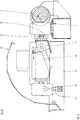
- the cross-member (3) pushed by the arm (25), first performs a small approaching travel towards the screw conveyor (on the right in figure 2 ), the slats (28) go to rest on the can, the suction cup (27) enters aspirating mode and stably retains the cans; the arm (25) translates towards the left (as indicated by the arrow in figures 2 of table 2) guided in the support and carrying the cross-member (3) and the cans with it.
- a cam, as well as the horizontal guide track, is fashioned on the support opposite the cam of figure 2 , which cam, according to a known method, rotates the cross-member by 180° so as to take the cans, in the overturned position, above the series of in-line jets (13) supplied by the jet-bearing bar (24); a jet of water strikes the inside of the can and carries out the rinsing.
- the cans return to the screw conveyor which obviously is stationary and waiting; as soon as the cans are on the line (1) and coupled to the screw conveyor, the suction cups deactivate, the cross-member (3) moves slightly away, the screw conveyor rotates so that the six rinsed cans are released and another six are collected from the waiting queue.
- the above-described sequence is summarised in figures 12, 13 and 14 of table 9.
- the released cans transported by the belt on the line (1), accumulate against the pad (7) guided along the trajectory by the border (4) which is in a raised position; the arm (8) performs a small translation to approach the gripping blocks (5) to the cans, pushing them to rest on the above-mentioned border (4) after which the suction cups (27) enter into action and stably retain the cans against the prismatic seatings of the blocks.
- the border (4) has many functions: when it is raised, it guides the just-rinsed cans along the pathway, and then functions as a rest during the gripping step and lastly in the lowered position (retracted) it is an element of continuity with the sliding plane (37) with which it aligns.
- the profile of the bent metal sheet which constitutes the border is designed so that each of the three elements thereof responds to a specific function: the short portion, in a raised position, assumes a vertical position so that is parallel to the flank of the cans; the end of the long portion opposite the first, resting on the plane (37), acts as a reaction against the pushing that the can receives during the gripping step; in the lowered position, the intermediate portion lies on the same plane as the plane (37).
- the long portion functions as a cam during the extension and/or the retraction movement; it is in fact kept pressed in contact against the edge of the plane (37) from the elastic torsion system (39) inserted on the fulcrum pin connecting the base support (38) with the sliding guide group (40); in figure 5 of table 4 the arrow indicates the direction in which the spring acts on the guide (40).
- the translation movement or more precisely the extension of the retractable border takes place by means of a pneumatic cylinder, which is not illustrated in the tables, but the installation thereof flanked to the guide (40) is simple to understand.
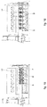
- the transfer arm (8) at the service of the first line, is responsible for the gripping functions of the cans (as already indicated), for the spacing thereof in the predetermined interaxis and the transfer thereof to the filling station; it supports the sliding guides (71), the linear actuator (35) and the bar (32), connects to the sliding guide (9) and is moved in translation by the linear actuator (10).
- the six blocks (5) are supported by the two guide bars (71) on which they can slide, are connected to one another by a flexible belt (6), solidly constrained to each block by the cylindrical pegs (29); the first block (on the left in the layout of table 1) engages in the drawing pin of the bracket (33) so that it is drawn from the linear movement of the actuator (35) to which the bracket is solidly constrained.
- the actuator (35) closes, the first block presses on the spacer (34) and so on until all the group of blocks and spacers are packed: the interaxis between the prisms of the blocks must coincide with that of the approached cans, i.e. equal to the diameter thereof.
- This is the configuration illustrated schematically in figure 15 of table 10 and which makes possible the approach of the blocks to the cans and the gripping thereof; in this condition, the belt (6) portion comprised between two contiguous blocks is slowed down and forms a wave; the supply to the suction cups (27) is done via an internal channelling of the block and by means of the flexible tubes (31) connected by the fittings (30) to the perforated supply bar (32).
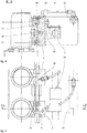
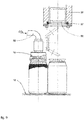
- each of the six plates is lifted, pushed by the rod (47) of the relative pneumatic cylinder, and brings the can to press with the edge of the mouth on the gasket (43) of the filling head (42) ( figure 7 of table 5 and diagram of figure 19 , table 12).
- the first de-aeration operation can then take place, followed by the pressurised filling of the beverage (beer, carbonated beverages in general, etc.) contained in the tank (41); the filling is done contemporaneously on all six heads and the seal is guaranteed by the fact that each can has its own pushing cylinder.
- the pinion (50) has a straight-toothed external cogging so as to be able to freely axially slide (to be raised) while remaining coupled to the rack (46); this rack is guided by the rollers (44), idle on the pins (45), and can slide on the action of the pneumatic cylinder (51).
- the connection between the cylinder and rack is guaranteed by the link bar (52), screws (53) and spacers (54).
- the translational movement of the rack (activated by the cylinder) transforms into rotary motion of the six enmeshed pinions (sprockets) and the overlying can-bearing plates; a precise regulation of the stroke of the piston guarantees a precise 180° rotation.
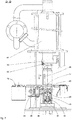
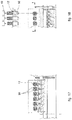
- the arm (16), slidable on the guide (15), is activated by the linear actuator (14); it approaches the cans which now have the resting pins (36) opposite, activates the suction cups and releases the cans on its return (see figure 20 of table 12) only when the cans are on the second line (18).
- the second line conveys the cans to the lid-placing station (22) in which the operations take place with the can stationary (diagram of figure 21 , table 13); the operations that take place in this station are two and, for functional reasons, they must be done in close succession.
- the first operation is the de-aeration, with a flow of carbon dioxide above the free surface of the beer (head zone of the can) and immediately after the lid is placed, so as to prevent return of previously-expelled air.
- a first blocking device (20) is destined to halt the can beneath the mouth (19) distributing carbon dioxide ( figure 9 of table 7), the adjacent can (already de-aerated) is also halted, by a blocking device not illustrated in the figure, directly below the lid loader and the time that passes for the transfer between the first and the second position is extremely short.
- the distribution of lids passes through a first rotating store (21) having a plurality of stations which supply the underlying loader (56); in the loader, the pack of lids is retained by a toroidal ring (57), an inner lip of which is elastic and allows release of one lid at a time.
- the lids are stacked with the external face thereof facing downwards, so that in order to go to rest on the mouth of the can the lid has to be translated, accompanied by a 180° rotation.
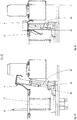
- the device for movement and placing of the lid in a pneumatically-activated preferred embodiment based on mechanical mechanisms (levers and cams), is illustrated in figures 10 and 11 of table 8.
- the member collecting the lid (overturned) from the loader (56) is the suction cup (59) housed in the beaker (65); two pins are applied to said beaker, by 90° with respect to the axis of the suction cup: the hollow pin (68) which crosses the central hole and the fitting (30) supplies the aspiration of the suction cup and the pin (69), solidly constrained to the con rod (66), which receives therefrom the command for rotating the beaker.
- the vertical translation is guided by the sliding guide group (60) fixed to the cam support (63), all being solidly constrained to the tube of the loader (56); the support (63) has a straight profile on which a U-shaped cut is made at about halfway along the travel thereof.
- this wall extends with a lug obtained by bending on which the rod of the double-acting pneumatic cylinder (61) is anchored; the end of the cylinder body is solidly constrained to the sliding arm (62) fixed in turn on the cursor of the linear guide group (60).
- the rod By supplying the upper chamber of the cylinder, the rod extends, the body of the cylinder and arm (62) are all positioned high, and the beaker with the suction cup collects the lid as illustrated in bold in figure 10 .
- the roller (67) constituted by a roller bearing moves first on the straight portion of the cam so that the beaker performs a simple translation, when the U-shaped recess is reached, the roller (67), recalled by the spring (64), penetrates therein and the beaker performs a first 90° rotation. Following the descent of the arm (62), the beaker performs a further 90° rotation, i.e. completely overturns, and in the final straight portion of travel the lid is placed on the can.
- roller of the lid/can edge is not described, as it is prior art; it is only stressed that this station is inserted in the machine, as described, so as to constitute a true single-block.
- linear machine can be applied to this layout as no operation takes place on a rotary-type machine; the transfer of the cans from a first line to a second line, parallel thereto, enables to keep the machine compact and to contemporaneously carry out a plurality of operational steps.
- the fixing of the lid with the pick and place system, to be carried out with the can stationary not only has the advantage of non-contamination, as mentioned in the foregoing, and precise placing even in the presence of a foam covering, but also enables managing the second de-aeration operation to best effect whether it takes place in the position that precedes the lid placing by means of the mouth (19), or it is desired to carry it out immediately prior to the placing of the lid. In the latter case, a few seconds before the lid is placed a final spray of antioxidant gas can be directed into the high zone of the can.
- This versatility of the machine enables optimum filling of the beers produced with the widest range of recipes and other types of carbonated beverages too, independently of the degree of foaminess they have.
Landscapes
- Engineering & Computer Science (AREA)
- Mechanical Engineering (AREA)
- Filling Of Jars Or Cans And Processes For Cleaning And Sealing Jars (AREA)
- Specific Conveyance Elements (AREA)
Claims (8)
- Block-Anlage für Brauereien und Hersteller von kohlensäurehaltigen Getränken im Allgemeinen zum Spülen, Durchführen einer ersten Entlüftung, Füllung, möglicherweise Durchführen einer zweiten Entlüftung und zum Verschließen von Dosen, umfassend:- eine erste Linie (1), beispielsweise ein Förderband, auf die leere Dosen geladen werden;- einen Sammelschneckenförderer (2);- einen Querträger (3), der mehrere Elemente zum Greifen der Dosen trägt;- eine Anlage zur ersten Entlüftung und Füllung gemäß der isobaren Fülltechnologie, die mit einem Tank (41), relativen Versorgungsleitungen und Füllköpfen (42) versehen ist;- einen Wasch-/Spültank (12), der im Block eingebaut ist, wobei die Düsen (13) in Reihe angeordnet sind und gleichzeitig an einer Anzahl von Dosen arbeiten, die gleich der Anzahl der Füllköpfe ist;- einen ersten Transferarm (8) mit einer Reihe von Greifblöcken (5);- eine Hilfskante (4) vom einziehbaren Typ an Bord der ersten Linie;- eine Reihe von Platten (17) mit Aufstell- und Zentrierstiften (36) mit einem Mechanismus zum Anheben und Drehen der Platten, wobei eine jede einzelne Platte (17) sowohl mit einer vertikalen Hubbewegung, die in der Lage ist, die Dose während der ersten Entlüftung und der Füllung gegen eine Dichtung (43) eines der Köpfe gepresst zu behalten als auch einer Drehbewegung von 180°, die sie nach dem erneuten Abstieg ausübt, versehen ist;- eine Deckelplatzierungsstation, in der die Deckel auf die Dosen platziert werden;- eine zweite Linie (18) zum Befördern der Dosen zu den Deckelplatzierungs- und Deckelverschlussstationen;- einen zweiten Transferarm (16) an einer Seite der zweiten Linie;dadurch gekennzeichnet, dass- ein Greifen der leeren Dosen in den verschiedenen Bewegungen mittels Ansaugsaugnäpfen (27) erfolgt, das ein Greifsystem darstellt und keine Quetschungen und/oder dauerhaften Verformungen an den sehr schlanken Wänden der Dose sowohl beim Annähern als auch beim Greifen erzeugen kann, wobei der Querträger (3) mehrere Saugnäpfe zum Greifen der Dosen und die Reihe von Greifblöcken (5) des ersten Arms (8) mit relativen Saugnäpfen (27) trägt;- der erste Arm (8), der sich an einer Seite der ersten Linie befindet, mit einem Sperrkissen (7) und einer Vorrichtung zum Realisieren von zwei unterschiedlichen Abstandszwischenachsen für die Dosen und einer Translationsbewegung, die in der Lage ist, die Dosen auf die Platten (17) zu transferieren, versehen ist, wobei die Saugnäpfe (27) an den Greifblöcken (5) durch einen Riemen (6) zusammengefügt sind, der auf Führungsstangen (71) verschiebbar ist;- die zweite Linie (18) parallel zur ersten Linie (1) verläuft, sie empfängt die vollen Dosen, die vom zweiten Transferarm (16) auf den Platten (17) entfernt wurden, und sie an die folgenden Stationen transferiert;- ein Sternförderer (11) mit angebrachter Rollengruppe (23) zum Verschließen des Deckels vorgesehen ist.
- Maschine nach Anspruch 1, dadurch gekennzeichnet, dass sie umfasst:- einen Gasspendermund (19) für eine zweite Entlüftung;- einen Speicher (21) zum Aufbewahren von Deckelpackungen eines rotierenden Trommeltyps;wobei die Dose, die sich neben der Dose befindet, die den Schritt zum Platzieren des Deckels durchläuft, vorübergehend unter dem Mund (19) anhält, der einen Kohlendioxidstrom auf den Mund der Dose für eine zweite Entlüftung abgibt;
wobei die Deckelplatzierungsstation von einem rotierenden Speicher (21) überragt ist, der einem Lader der Deckel Deckel zuführt;
wobei jeder einzelne Deckel von einem Saugnapf (59) an seiner Außenseite erfasst, vom Lader (56) gesammelt und während des Transfers um 180° gedreht, zentriert und auf dem oberen Rand der Dose gelegt wird. - Maschine nach Anspruch 2, dadurch gekennzeichnet, dass eine Spülstation den Arm (3) umfasst, der die Reihe von Ansaugsaugnäpfen (27) trägt, die in der Lage sind, die auf dem Schneckenförderer (2) ruhenden Dosen zu sammeln,
wobei der Arm (3), der die Reihe von Ansaugsaugnäpfen (27) trägt, eine Rotations-Translationsbewegung ausführt, bis er die in vertikaler Position umgekippten Dosen über die Wasserstrahlen (13) bringt. - Maschine nach Anspruch 2, dadurch gekennzeichnet, dass an Bord der ersten Linie (1) in Richtung eines Inneren der Maschine die bewegliche einziehbare Hilfskante (4) angebracht ist, die in angehobener Position zunächst als Führung für die Dosen unmittelbar nach dem Spülen wirkt, während sie gegen das Sperrkissen (7) transferiert werden, und anschließend als Reaktionskraft für die Dosen wirkt, wenn der erste Arm (8) die Greifannäherung durch Drücken mit den Saugnäpfen ausführt; nach dem Ausführen dieser Funktionen gleitet die von einem Pneumatikzylinder zurückgerufene Kante auf eine Führung (40) und senkt sich auf das Niveau der Gleitebene (37) ab, um einen nachfolgenden Durchgang der Dosen zu ermöglichen.
- Maschine nach Anspruch 2, dadurch gekennzeichnet, dass die Blöcke (5) zwei V-förmige Prismen zum Ausrichten und Zentrieren der Dose, einen der Ansaugsaugnäpfe (27) zum Greifen der Dose aufweisen und dadurch, dass die Blöcke auf zwei der Führungsstangen (71) verschiebbar sind.
- Maschine nach den Ansprüchen 4 und 5, dadurch gekennzeichnet, dass die Blöcke (5) miteinander verbunden sind und an einer gleichen Zwischenachse durch einen Zahnriemen (6) positioniert sind, der flexibel, aber nicht dehnbar ist; der letzte Block ist an den Führungsstangen fixiert, der erste ist mit dem externen Läufer eines Aktuators (35) verbunden, dessen Endhubpositionen jeweils die Konfiguration der angenäherten Blöcke und die Konfiguration der offenen Blöcke definieren: die erste Zwischenachse ist durch die Dicke eines Abstandshalters (34) definiert und entspricht dem Durchmesser der Dose, die zweite Zwischenachse ist durch das Vielfache der Teilungen des Riemens (6) definiert, in denen die Fixierung mit Zapfen (29) stattfindet und gleich der Zwischenachse der Platten (17) und der darüber liegenden Füllköpfe ist.
- Maschine nach Anspruch 2, dadurch gekennzeichnet, dass die Platten (17) in dem Teil, der normalerweise aus der Gleitebene austritt, mit zwei der Stifte (36) versehen sind, auf denen die Dose in dem unter der Arbeitsebene liegenden Teil ruht und zentriert ist, die Platte mit einem langen Getriebe (50) verlängert ist, das durch ein Paar Rollenlager (48) an einer Nabe (49) fest befestigt ist, die an einer Stange (47) eines Hubzylinders (51) fixiert ist; wenn sich die Dosen in Position auf der Platte befinden, drückt der Zylinder die Dosen nach oben zum Verschließen gegen die Dichtung (43) eines der isobaren Füllköpfe (42).
- Maschine nach Anspruch 7, gekennzeichnet durch eine Zahnstange (46), die auf den Rollen (44) verschiebbar ist, deren gerade Verzahnung in die Getriebe (50) der Platten eingreift, die Platten in gegenseitiger Phase hält und sie um 180° durch die Wirkung eines vorbestimmten Hubs der Zahnstange, die auf die Stange des Zylinders (51) ausgeübt wird, dreht.
Priority Applications (1)
| Application Number | Priority Date | Filing Date | Title |
|---|---|---|---|
| SI201730348T SI3241803T1 (sl) | 2016-05-02 | 2017-04-28 | Stroj z linearnim enojnim blokom za izpiranje, polnjenje in zapiranje pločevink za pijače |
Applications Claiming Priority (1)
| Application Number | Priority Date | Filing Date | Title |
|---|---|---|---|
| ITUA2016A003655A ITUA20163655A1 (it) | 2016-05-02 | 2016-05-02 | Macchina lineare monoblocco per risciacquo riempimento e sigillatura coperchio delle lattine di bevande gassate ed in particolare birra |
Publications (2)
| Publication Number | Publication Date |
|---|---|
| EP3241803A1 EP3241803A1 (de) | 2017-11-08 |
| EP3241803B1 true EP3241803B1 (de) | 2020-05-06 |
Family
ID=56801751
Family Applications (1)
| Application Number | Title | Priority Date | Filing Date |
|---|---|---|---|
| EP17168827.8A Active EP3241803B1 (de) | 2016-05-02 | 2017-04-28 | Lineare block-anlage für spülen, füllen und verschliessen von getränkedosen |
Country Status (3)
| Country | Link |
|---|---|
| EP (1) | EP3241803B1 (de) |
| IT (1) | ITUA20163655A1 (de) |
| SI (1) | SI3241803T1 (de) |
Cited By (1)
| Publication number | Priority date | Publication date | Assignee | Title |
|---|---|---|---|---|
| CN110723704A (zh) * | 2019-10-24 | 2020-01-24 | 李克文 | 一种塑料瓶塞生产设备 |
Families Citing this family (16)
| Publication number | Priority date | Publication date | Assignee | Title |
|---|---|---|---|---|
| CN108190818B (zh) * | 2017-12-28 | 2020-09-15 | 楚天科技股份有限公司 | 一种抽真空充氮灌装机 |
| FR3079061B1 (fr) * | 2018-03-15 | 2021-05-14 | Fl Participations | Dispositif de distribution de produits de type boisson |
| CN109205170B (zh) * | 2018-07-17 | 2024-08-23 | 张家界大庸泉饮品有限公司 | 一种矿泉水生产线 |
| CN110228779A (zh) * | 2019-06-27 | 2019-09-13 | 佛山艾嘉化妆品有限公司 | 一种化妆品瓶体加工输送机构 |
| CN110340063B (zh) * | 2019-08-07 | 2021-09-28 | 河海大学常州校区 | 一种多型号的轴承清洗功能的机械臂 |
| CN112027136A (zh) * | 2020-08-20 | 2020-12-04 | 方家铺子(莆田)绿色食品有限公司 | 一种用于鲍鱼罐头加工的自动加卤汁机 |
| CN112722374B (zh) * | 2021-01-05 | 2023-10-03 | 湖南省幽吉茶业有限公司 | 一种罐装茶叶封口装置 |
| CN113262523B (zh) * | 2021-05-17 | 2022-10-25 | 山东迪森生物科技有限公司 | 一种生物医药用超临界萃取设备 |
| CN114515734A (zh) * | 2022-02-23 | 2022-05-20 | 广州达意隆包装机械股份有限公司 | 分配器和洗瓶机 |
| CN115448023A (zh) * | 2022-09-19 | 2022-12-09 | 广东歌得智能装备有限公司 | 一种转盘运料装置 |
| IT202200020928A1 (it) * | 2022-10-11 | 2024-04-11 | Gruppo Bisaro Sifa Srl | Macchina riempitrice per lattine e metodo per il riempimento di lattine. |
| US12459686B2 (en) | 2023-06-15 | 2025-11-04 | Primoreels A/S | Device for placing lids on containers |
| CN116654844A (zh) * | 2023-08-02 | 2023-08-29 | 兴化市宝中宝化妆品有限公司 | 一种灌洗液生产设备 |
| CN116854019A (zh) * | 2023-08-22 | 2023-10-10 | 辽宁鑫富涞智能科技有限公司 | 一种新型桶装水冲洗灌装机 |
| CN117505364B (zh) * | 2023-12-29 | 2024-03-22 | 泰州市江南机械制造有限公司 | 一种立式加工机床刀具用清洗装置 |
| CN119284816A (zh) * | 2024-12-10 | 2025-01-10 | 山东毅康新材料有限公司 | 一种具有改进结构的密封胶灌装设备 |
Family Cites Families (4)
| Publication number | Priority date | Publication date | Assignee | Title |
|---|---|---|---|---|
| US1889629A (en) * | 1928-07-19 | 1932-11-29 | Seitz Werke Gmbh | Method of filling and sealing bottles, vessels, and the like |
| US3545160A (en) * | 1968-12-05 | 1970-12-08 | Continental Can Co | Method and apparatus for purging headspaces of filled cans |
| DE9002033U1 (de) * | 1990-02-21 | 1990-04-26 | Krones Ag Hermann Kronseder Maschinenfabrik, 8402 Neutraubling | Sauggreifer für Gefäße |
| DE19702770C2 (de) * | 1997-01-27 | 2001-06-07 | Alfill Engineering Gmbh & Co K | Behandlungsvorrichtung für Getränkebehälter mit mehreren integrierten Behandlungseinrichtungen |
-
2016
- 2016-05-02 IT ITUA2016A003655A patent/ITUA20163655A1/it unknown
-
2017
- 2017-04-28 EP EP17168827.8A patent/EP3241803B1/de active Active
- 2017-04-28 SI SI201730348T patent/SI3241803T1/sl unknown
Non-Patent Citations (1)
| Title |
|---|
| None * |
Cited By (1)
| Publication number | Priority date | Publication date | Assignee | Title |
|---|---|---|---|---|
| CN110723704A (zh) * | 2019-10-24 | 2020-01-24 | 李克文 | 一种塑料瓶塞生产设备 |
Also Published As
| Publication number | Publication date |
|---|---|
| SI3241803T1 (sl) | 2020-10-30 |
| EP3241803A1 (de) | 2017-11-08 |
| ITUA20163655A1 (it) | 2017-11-02 |
Similar Documents
| Publication | Publication Date | Title |
|---|---|---|
| EP3241803B1 (de) | Lineare block-anlage für spülen, füllen und verschliessen von getränkedosen | |
| US9174832B2 (en) | Capping apparatus and capping system for bottle filling device | |
| EP2626328B1 (de) | Maschine zum Befüllen von Behältern mit Flüssigkeiten und Verfahren zum Befüllen von Behältern mit dieser Befüllungsmaschine | |
| EP3156341A1 (de) | Maschine zur befüllung von behältern | |
| US6832640B2 (en) | Device for gripping and handling bottles in a labeling machine and method of bottle filling/pressurising | |
| US5402623A (en) | Method and apparatus for closing bottles | |
| CN101691141B (zh) | 铝盒包装机 | |
| ES290362A1 (es) | Perfeccionamientos en las maquinas para lavar y llenar envases | |
| CN115947287B (zh) | 一种灌装封膜机 | |
| US7401445B2 (en) | Vessel-filling apparatus | |
| US5000661A (en) | Method of and apparatus for cleaning and filling containers | |
| CN103231908A (zh) | 超洁净预制杯灌装机 | |
| KR0178777B1 (ko) | 주형의 조형틀 형성 방법 및 주형 생산 시스템 | |
| WO2009004500A1 (en) | Filling valve for a filling machine | |
| EP3162721A1 (de) | Vorrichtung zur handhabung von behältern | |
| CN103303853A (zh) | 卡式瓶灌封机 | |
| EP3971130A1 (de) | Maschine zum füllen von behältern mit flüssigkeit und entsprechendes füllverfahren | |
| US2623274A (en) | Bail inserting machine | |
| US2879638A (en) | Machine for loading containers in a carton | |
| EP2287107A1 (de) | Rotierende Füllmaschine zum Füllen von Behältern mit Flüssigkeiten | |
| US5558138A (en) | Process and apparatus for cleaning container handling machines such as beverage can filling machines | |
| US3587208A (en) | Device for gripping and uncapping bottles and automatic handling machines provided with such devices | |
| EP0798263A1 (de) | Behälterverschliess-und Füllvorrichtung | |
| CN203199631U (zh) | 超洁净预制杯灌装机 | |
| JP4121337B2 (ja) | 缶搬送ライン用の缶ストッパー |
Legal Events
| Date | Code | Title | Description |
|---|---|---|---|
| PUAI | Public reference made under article 153(3) epc to a published international application that has entered the european phase |
Free format text: ORIGINAL CODE: 0009012 |
|
| STAA | Information on the status of an ep patent application or granted ep patent |
Free format text: STATUS: THE APPLICATION HAS BEEN PUBLISHED |
|
| AK | Designated contracting states |
Kind code of ref document: A1 Designated state(s): AL AT BE BG CH CY CZ DE DK EE ES FI FR GB GR HR HU IE IS IT LI LT LU LV MC MK MT NL NO PL PT RO RS SE SI SK SM TR |
|
| AX | Request for extension of the european patent |
Extension state: BA ME |
|
| STAA | Information on the status of an ep patent application or granted ep patent |
Free format text: STATUS: REQUEST FOR EXAMINATION WAS MADE |
|
| 17P | Request for examination filed |
Effective date: 20180423 |
|
| RBV | Designated contracting states (corrected) |
Designated state(s): AL AT BE BG CH CY CZ DE DK EE ES FI FR GB GR HR HU IE IS IT LI LT LU LV MC MK MT NL NO PL PT RO RS SE SI SK SM TR |
|
| STAA | Information on the status of an ep patent application or granted ep patent |
Free format text: STATUS: EXAMINATION IS IN PROGRESS |
|
| 17Q | First examination report despatched |
Effective date: 20181106 |
|
| REG | Reference to a national code |
Ref country code: DE Ref legal event code: R079 Ref document number: 602017015999 Country of ref document: DE Free format text: PREVIOUS MAIN CLASS: B67C0003220000 Ipc: B67C0007000000 |
|
| GRAP | Despatch of communication of intention to grant a patent |
Free format text: ORIGINAL CODE: EPIDOSNIGR1 |
|
| STAA | Information on the status of an ep patent application or granted ep patent |
Free format text: STATUS: GRANT OF PATENT IS INTENDED |
|
| RIC1 | Information provided on ipc code assigned before grant |
Ipc: B67C 3/22 20060101ALI20200109BHEP Ipc: B65B 7/28 20060101ALI20200109BHEP Ipc: B08B 3/02 20060101ALI20200109BHEP Ipc: B67C 7/00 20060101AFI20200109BHEP Ipc: B65B 3/04 20060101ALI20200109BHEP |
|
| INTG | Intention to grant announced |
Effective date: 20200131 |
|
| GRAS | Grant fee paid |
Free format text: ORIGINAL CODE: EPIDOSNIGR3 |
|
| GRAA | (expected) grant |
Free format text: ORIGINAL CODE: 0009210 |
|
| STAA | Information on the status of an ep patent application or granted ep patent |
Free format text: STATUS: THE PATENT HAS BEEN GRANTED |
|
| AK | Designated contracting states |
Kind code of ref document: B1 Designated state(s): AL AT BE BG CH CY CZ DE DK EE ES FI FR GB GR HR HU IE IS IT LI LT LU LV MC MK MT NL NO PL PT RO RS SE SI SK SM TR |
|
| REG | Reference to a national code |
Ref country code: GB Ref legal event code: FG4D |
|
| REG | Reference to a national code |
Ref country code: CH Ref legal event code: EP Ref country code: AT Ref legal event code: REF Ref document number: 1266436 Country of ref document: AT Kind code of ref document: T Effective date: 20200515 |
|
| REG | Reference to a national code |
Ref country code: IE Ref legal event code: FG4D |
|
| REG | Reference to a national code |
Ref country code: DE Ref legal event code: R096 Ref document number: 602017015999 Country of ref document: DE |
|
| REG | Reference to a national code |
Ref country code: LT Ref legal event code: MG4D |
|
| REG | Reference to a national code |
Ref country code: NL Ref legal event code: MP Effective date: 20200506 |
|
| PG25 | Lapsed in a contracting state [announced via postgrant information from national office to epo] |
Ref country code: LT Free format text: LAPSE BECAUSE OF FAILURE TO SUBMIT A TRANSLATION OF THE DESCRIPTION OR TO PAY THE FEE WITHIN THE PRESCRIBED TIME-LIMIT Effective date: 20200506 Ref country code: FI Free format text: LAPSE BECAUSE OF FAILURE TO SUBMIT A TRANSLATION OF THE DESCRIPTION OR TO PAY THE FEE WITHIN THE PRESCRIBED TIME-LIMIT Effective date: 20200506 Ref country code: SE Free format text: LAPSE BECAUSE OF FAILURE TO SUBMIT A TRANSLATION OF THE DESCRIPTION OR TO PAY THE FEE WITHIN THE PRESCRIBED TIME-LIMIT Effective date: 20200506 Ref country code: IS Free format text: LAPSE BECAUSE OF FAILURE TO SUBMIT A TRANSLATION OF THE DESCRIPTION OR TO PAY THE FEE WITHIN THE PRESCRIBED TIME-LIMIT Effective date: 20200906 Ref country code: GR Free format text: LAPSE BECAUSE OF FAILURE TO SUBMIT A TRANSLATION OF THE DESCRIPTION OR TO PAY THE FEE WITHIN THE PRESCRIBED TIME-LIMIT Effective date: 20200807 Ref country code: NO Free format text: LAPSE BECAUSE OF FAILURE TO SUBMIT A TRANSLATION OF THE DESCRIPTION OR TO PAY THE FEE WITHIN THE PRESCRIBED TIME-LIMIT Effective date: 20200806 Ref country code: PT Free format text: LAPSE BECAUSE OF FAILURE TO SUBMIT A TRANSLATION OF THE DESCRIPTION OR TO PAY THE FEE WITHIN THE PRESCRIBED TIME-LIMIT Effective date: 20200907 |
|
| PG25 | Lapsed in a contracting state [announced via postgrant information from national office to epo] |
Ref country code: HR Free format text: LAPSE BECAUSE OF FAILURE TO SUBMIT A TRANSLATION OF THE DESCRIPTION OR TO PAY THE FEE WITHIN THE PRESCRIBED TIME-LIMIT Effective date: 20200506 Ref country code: RS Free format text: LAPSE BECAUSE OF FAILURE TO SUBMIT A TRANSLATION OF THE DESCRIPTION OR TO PAY THE FEE WITHIN THE PRESCRIBED TIME-LIMIT Effective date: 20200506 Ref country code: LV Free format text: LAPSE BECAUSE OF FAILURE TO SUBMIT A TRANSLATION OF THE DESCRIPTION OR TO PAY THE FEE WITHIN THE PRESCRIBED TIME-LIMIT Effective date: 20200506 Ref country code: BG Free format text: LAPSE BECAUSE OF FAILURE TO SUBMIT A TRANSLATION OF THE DESCRIPTION OR TO PAY THE FEE WITHIN THE PRESCRIBED TIME-LIMIT Effective date: 20200806 |
|
| REG | Reference to a national code |
Ref country code: AT Ref legal event code: MK05 Ref document number: 1266436 Country of ref document: AT Kind code of ref document: T Effective date: 20200506 |
|
| PG25 | Lapsed in a contracting state [announced via postgrant information from national office to epo] |
Ref country code: AL Free format text: LAPSE BECAUSE OF FAILURE TO SUBMIT A TRANSLATION OF THE DESCRIPTION OR TO PAY THE FEE WITHIN THE PRESCRIBED TIME-LIMIT Effective date: 20200506 Ref country code: NL Free format text: LAPSE BECAUSE OF FAILURE TO SUBMIT A TRANSLATION OF THE DESCRIPTION OR TO PAY THE FEE WITHIN THE PRESCRIBED TIME-LIMIT Effective date: 20200506 |
|
| PG25 | Lapsed in a contracting state [announced via postgrant information from national office to epo] |
Ref country code: CZ Free format text: LAPSE BECAUSE OF FAILURE TO SUBMIT A TRANSLATION OF THE DESCRIPTION OR TO PAY THE FEE WITHIN THE PRESCRIBED TIME-LIMIT Effective date: 20200506 Ref country code: ES Free format text: LAPSE BECAUSE OF FAILURE TO SUBMIT A TRANSLATION OF THE DESCRIPTION OR TO PAY THE FEE WITHIN THE PRESCRIBED TIME-LIMIT Effective date: 20200506 Ref country code: EE Free format text: LAPSE BECAUSE OF FAILURE TO SUBMIT A TRANSLATION OF THE DESCRIPTION OR TO PAY THE FEE WITHIN THE PRESCRIBED TIME-LIMIT Effective date: 20200506 Ref country code: SM Free format text: LAPSE BECAUSE OF FAILURE TO SUBMIT A TRANSLATION OF THE DESCRIPTION OR TO PAY THE FEE WITHIN THE PRESCRIBED TIME-LIMIT Effective date: 20200506 Ref country code: DK Free format text: LAPSE BECAUSE OF FAILURE TO SUBMIT A TRANSLATION OF THE DESCRIPTION OR TO PAY THE FEE WITHIN THE PRESCRIBED TIME-LIMIT Effective date: 20200506 Ref country code: RO Free format text: LAPSE BECAUSE OF FAILURE TO SUBMIT A TRANSLATION OF THE DESCRIPTION OR TO PAY THE FEE WITHIN THE PRESCRIBED TIME-LIMIT Effective date: 20200506 Ref country code: AT Free format text: LAPSE BECAUSE OF FAILURE TO SUBMIT A TRANSLATION OF THE DESCRIPTION OR TO PAY THE FEE WITHIN THE PRESCRIBED TIME-LIMIT Effective date: 20200506 Ref country code: IT Free format text: LAPSE BECAUSE OF FAILURE TO SUBMIT A TRANSLATION OF THE DESCRIPTION OR TO PAY THE FEE WITHIN THE PRESCRIBED TIME-LIMIT Effective date: 20200506 |
|
| REG | Reference to a national code |
Ref country code: DE Ref legal event code: R097 Ref document number: 602017015999 Country of ref document: DE |
|
| PG25 | Lapsed in a contracting state [announced via postgrant information from national office to epo] |
Ref country code: PL Free format text: LAPSE BECAUSE OF FAILURE TO SUBMIT A TRANSLATION OF THE DESCRIPTION OR TO PAY THE FEE WITHIN THE PRESCRIBED TIME-LIMIT Effective date: 20200506 Ref country code: SK Free format text: LAPSE BECAUSE OF FAILURE TO SUBMIT A TRANSLATION OF THE DESCRIPTION OR TO PAY THE FEE WITHIN THE PRESCRIBED TIME-LIMIT Effective date: 20200506 |
|
| PLBE | No opposition filed within time limit |
Free format text: ORIGINAL CODE: 0009261 |
|
| STAA | Information on the status of an ep patent application or granted ep patent |
Free format text: STATUS: NO OPPOSITION FILED WITHIN TIME LIMIT |
|
| 26N | No opposition filed |
Effective date: 20210209 |
|
| PG25 | Lapsed in a contracting state [announced via postgrant information from national office to epo] |
Ref country code: MC Free format text: LAPSE BECAUSE OF FAILURE TO SUBMIT A TRANSLATION OF THE DESCRIPTION OR TO PAY THE FEE WITHIN THE PRESCRIBED TIME-LIMIT Effective date: 20200506 |
|
| GBPC | Gb: european patent ceased through non-payment of renewal fee |
Effective date: 20210428 |
|
| PG25 | Lapsed in a contracting state [announced via postgrant information from national office to epo] |
Ref country code: LU Free format text: LAPSE BECAUSE OF NON-PAYMENT OF DUE FEES Effective date: 20210428 |
|
| REG | Reference to a national code |
Ref country code: BE Ref legal event code: MM Effective date: 20210430 |
|
| PG25 | Lapsed in a contracting state [announced via postgrant information from national office to epo] |
Ref country code: LI Free format text: LAPSE BECAUSE OF NON-PAYMENT OF DUE FEES Effective date: 20210430 Ref country code: CH Free format text: LAPSE BECAUSE OF NON-PAYMENT OF DUE FEES Effective date: 20210430 Ref country code: FR Free format text: LAPSE BECAUSE OF NON-PAYMENT OF DUE FEES Effective date: 20210430 Ref country code: GB Free format text: LAPSE BECAUSE OF NON-PAYMENT OF DUE FEES Effective date: 20210428 |
|
| PG25 | Lapsed in a contracting state [announced via postgrant information from national office to epo] |
Ref country code: IE Free format text: LAPSE BECAUSE OF NON-PAYMENT OF DUE FEES Effective date: 20210428 |
|
| PG25 | Lapsed in a contracting state [announced via postgrant information from national office to epo] |
Ref country code: BE Free format text: LAPSE BECAUSE OF NON-PAYMENT OF DUE FEES Effective date: 20210430 |
|
| PG25 | Lapsed in a contracting state [announced via postgrant information from national office to epo] |
Ref country code: HU Free format text: LAPSE BECAUSE OF FAILURE TO SUBMIT A TRANSLATION OF THE DESCRIPTION OR TO PAY THE FEE WITHIN THE PRESCRIBED TIME-LIMIT; INVALID AB INITIO Effective date: 20170428 |
|
| PG25 | Lapsed in a contracting state [announced via postgrant information from national office to epo] |
Ref country code: CY Free format text: LAPSE BECAUSE OF FAILURE TO SUBMIT A TRANSLATION OF THE DESCRIPTION OR TO PAY THE FEE WITHIN THE PRESCRIBED TIME-LIMIT Effective date: 20200506 |
|
| PGFP | Annual fee paid to national office [announced via postgrant information from national office to epo] |
Ref country code: DE Payment date: 20230427 Year of fee payment: 7 |
|
| PGFP | Annual fee paid to national office [announced via postgrant information from national office to epo] |
Ref country code: SI Payment date: 20230407 Year of fee payment: 7 |
|
| PG25 | Lapsed in a contracting state [announced via postgrant information from national office to epo] |
Ref country code: MK Free format text: LAPSE BECAUSE OF FAILURE TO SUBMIT A TRANSLATION OF THE DESCRIPTION OR TO PAY THE FEE WITHIN THE PRESCRIBED TIME-LIMIT Effective date: 20200506 |
|
| PG25 | Lapsed in a contracting state [announced via postgrant information from national office to epo] |
Ref country code: MT Free format text: LAPSE BECAUSE OF FAILURE TO SUBMIT A TRANSLATION OF THE DESCRIPTION OR TO PAY THE FEE WITHIN THE PRESCRIBED TIME-LIMIT Effective date: 20200506 |
|
| REG | Reference to a national code |
Ref country code: DE Ref legal event code: R119 Ref document number: 602017015999 Country of ref document: DE |
|
| PG25 | Lapsed in a contracting state [announced via postgrant information from national office to epo] |
Ref country code: DE Free format text: LAPSE BECAUSE OF NON-PAYMENT OF DUE FEES Effective date: 20241105 |
|
| PG25 | Lapsed in a contracting state [announced via postgrant information from national office to epo] |
Ref country code: DE Free format text: LAPSE BECAUSE OF NON-PAYMENT OF DUE FEES Effective date: 20241105 |
|
| PG25 | Lapsed in a contracting state [announced via postgrant information from national office to epo] |
Ref country code: TR Free format text: LAPSE BECAUSE OF FAILURE TO SUBMIT A TRANSLATION OF THE DESCRIPTION OR TO PAY THE FEE WITHIN THE PRESCRIBED TIME-LIMIT Effective date: 20200506 |