EP3241768B1 - Vorrichtung zur übergabe von folienbeuteln - Google Patents
Vorrichtung zur übergabe von folienbeuteln Download PDFInfo
- Publication number
- EP3241768B1 EP3241768B1 EP16167896.6A EP16167896A EP3241768B1 EP 3241768 B1 EP3241768 B1 EP 3241768B1 EP 16167896 A EP16167896 A EP 16167896A EP 3241768 B1 EP3241768 B1 EP 3241768B1
- Authority
- EP
- European Patent Office
- Prior art keywords
- bag
- foil
- support elements
- bottom support
- height
- Prior art date
- Legal status (The legal status is an assumption and is not a legal conclusion. Google has not performed a legal analysis and makes no representation as to the accuracy of the status listed.)
- Not-in-force
Links
Images


Classifications
-
- B—PERFORMING OPERATIONS; TRANSPORTING
- B65—CONVEYING; PACKING; STORING; HANDLING THIN OR FILAMENTARY MATERIAL
- B65B—MACHINES, APPARATUS OR DEVICES FOR, OR METHODS OF, PACKAGING ARTICLES OR MATERIALS; UNPACKING
- B65B43/00—Forming, feeding, opening or setting-up containers or receptacles in association with packaging
- B65B43/26—Opening or distending bags; Opening, erecting, or setting-up boxes, cartons, or carton blanks
- B65B43/28—Opening or distending bags; Opening, erecting, or setting-up boxes, cartons, or carton blanks by grippers co-operating with fixed supports
-
- B—PERFORMING OPERATIONS; TRANSPORTING
- B65—CONVEYING; PACKING; STORING; HANDLING THIN OR FILAMENTARY MATERIAL
- B65B—MACHINES, APPARATUS OR DEVICES FOR, OR METHODS OF, PACKAGING ARTICLES OR MATERIALS; UNPACKING
- B65B43/00—Forming, feeding, opening or setting-up containers or receptacles in association with packaging
- B65B43/12—Feeding flexible bags or carton blanks in flat or collapsed state; Feeding flat bags connected to form a series or chain
- B65B43/14—Feeding individual bags or carton blanks from piles or magazines
- B65B43/16—Feeding individual bags or carton blanks from piles or magazines by grippers
-
- B—PERFORMING OPERATIONS; TRANSPORTING
- B65—CONVEYING; PACKING; STORING; HANDLING THIN OR FILAMENTARY MATERIAL
- B65B—MACHINES, APPARATUS OR DEVICES FOR, OR METHODS OF, PACKAGING ARTICLES OR MATERIALS; UNPACKING
- B65B43/00—Forming, feeding, opening or setting-up containers or receptacles in association with packaging
- B65B43/42—Feeding or positioning bags, boxes, or cartons in the distended, opened, or set-up state; Feeding preformed rigid containers, e.g. tins, capsules, glass tubes, glasses, to the packaging position; Locating containers or receptacles at the filling position; Supporting containers or receptacles during the filling operation
- B65B43/44—Feeding or positioning bags, boxes, or cartons in the distended, opened, or set-up state; Feeding preformed rigid containers, e.g. tins, capsules, glass tubes, glasses, to the packaging position; Locating containers or receptacles at the filling position; Supporting containers or receptacles during the filling operation from supply magazines
-
- B—PERFORMING OPERATIONS; TRANSPORTING
- B65—CONVEYING; PACKING; STORING; HANDLING THIN OR FILAMENTARY MATERIAL
- B65B—MACHINES, APPARATUS OR DEVICES FOR, OR METHODS OF, PACKAGING ARTICLES OR MATERIALS; UNPACKING
- B65B43/00—Forming, feeding, opening or setting-up containers or receptacles in association with packaging
- B65B43/42—Feeding or positioning bags, boxes, or cartons in the distended, opened, or set-up state; Feeding preformed rigid containers, e.g. tins, capsules, glass tubes, glasses, to the packaging position; Locating containers or receptacles at the filling position; Supporting containers or receptacles during the filling operation
- B65B43/46—Feeding or positioning bags, boxes, or cartons in the distended, opened, or set-up state; Feeding preformed rigid containers, e.g. tins, capsules, glass tubes, glasses, to the packaging position; Locating containers or receptacles at the filling position; Supporting containers or receptacles during the filling operation using grippers
-
- B—PERFORMING OPERATIONS; TRANSPORTING
- B65—CONVEYING; PACKING; STORING; HANDLING THIN OR FILAMENTARY MATERIAL
- B65B—MACHINES, APPARATUS OR DEVICES FOR, OR METHODS OF, PACKAGING ARTICLES OR MATERIALS; UNPACKING
- B65B43/00—Forming, feeding, opening or setting-up containers or receptacles in association with packaging
- B65B43/42—Feeding or positioning bags, boxes, or cartons in the distended, opened, or set-up state; Feeding preformed rigid containers, e.g. tins, capsules, glass tubes, glasses, to the packaging position; Locating containers or receptacles at the filling position; Supporting containers or receptacles during the filling operation
- B65B43/46—Feeding or positioning bags, boxes, or cartons in the distended, opened, or set-up state; Feeding preformed rigid containers, e.g. tins, capsules, glass tubes, glasses, to the packaging position; Locating containers or receptacles at the filling position; Supporting containers or receptacles during the filling operation using grippers
- B65B43/465—Feeding or positioning bags, boxes, or cartons in the distended, opened, or set-up state; Feeding preformed rigid containers, e.g. tins, capsules, glass tubes, glasses, to the packaging position; Locating containers or receptacles at the filling position; Supporting containers or receptacles during the filling operation using grippers for bags
-
- B—PERFORMING OPERATIONS; TRANSPORTING
- B65—CONVEYING; PACKING; STORING; HANDLING THIN OR FILAMENTARY MATERIAL
- B65B—MACHINES, APPARATUS OR DEVICES FOR, OR METHODS OF, PACKAGING ARTICLES OR MATERIALS; UNPACKING
- B65B59/00—Arrangements to enable machines to handle articles of different sizes, to produce packages of different sizes, to vary the contents of packages, to handle different types of packaging material, or to give access for cleaning or maintenance purposes
- B65B59/003—Arrangements to enable adjustments related to the packaging material
-
- B—PERFORMING OPERATIONS; TRANSPORTING
- B65—CONVEYING; PACKING; STORING; HANDLING THIN OR FILAMENTARY MATERIAL
- B65G—TRANSPORT OR STORAGE DEVICES, e.g. CONVEYORS FOR LOADING OR TIPPING, SHOP CONVEYOR SYSTEMS OR PNEUMATIC TUBE CONVEYORS
- B65G37/00—Combinations of mechanical conveyors of the same kind, or of different kinds, of interest apart from their application in particular machines or use in particular manufacturing processes
Definitions
- the invention relates to a device for transferring foil bags comprising a magazine system with a plurality of juxtaposed foil bag magazines, a plurality of juxtaposed bag receptacles for simultaneously transporting juxtaposed foil bags, each bag receptacle is designed for lateral support and holding one of the foil bag and comprises brackets, each for Grasping a foil bag in a bag receptacle and for hanging transporting the foil bag are formed, wherein the device is designed such that in operation foil bag from the foil bag magazines passed to the bag receptacles and are gripped in the bag receptacles by the clip and hanging.
- receiving boxes are used to transfer the foil bag, each having a dedicated floor.
- the bottom supports the bottom of the foil bag during transport.
- this system has several disadvantages.
- the receiving boxes have a large mass, which negatively affects overall energy consumption.
- these receiving boxes with bottom are only suitable for foil bags of a length extension (or height).
- the foil pouches are gripped at a fixed height by the clamps. Pouches that are shorter must therefore be transported in a receiving box with a higher floor, which brings them to the appropriate height. This means that a format change requires that the receiving box be replaced or each floor is adjusted individually.
- An object of the invention is to eliminate the above drawbacks, in particular to provide a device in which the power consumption is reduced and the format change is simplified.
- the device comprises height-adjustable floor support elements, which are designed and arranged such that they each support the bottom of a foil bag in a bag receptacle from below to the position at which the brackets grip the foil bag.
- bag holders can be used without bottom, since no more ground is necessary when the brackets grip the foil bag. This reduces the energy consumption because the bag receptacles have a lower mass.
- the bag holder itself can remain unchanged when a format change takes place, since it is sufficient to adjust the bottom support elements independently of the bag receptacles. Thus, the format change is simplified.
- Film bags are formed, for example, welded together from a plurality of films, that they include a cavity which is open on one side.
- the open side is used to fill the foil pouches, for example with a liquid product.
- this page is referred to as the upper end of the film bag.
- the staples grip the foil bags laterally at their upper ends.
- the side of the foil bag opposite the open side is called the bottom.
- the foil pouches are flat when handed over to the pouch receptacle. In the bag receptacles then the larger of the side surfaces of the film bag in or against the transport direction and the narrow sides of the film bag are laterally supported by the bag receptacle.
- a bag receptacle has at least two opposing holding elements, between which the film bag is inserted.
- a retention element may include a side support member configured to laterally support the sides of the foil pouches.
- each retaining element may comprise one of the brackets.
- the side support elements may each comprise a receptacle for receiving one side of a foil bag, wherein the holding elements are arranged in operation such that the receptacles of the opposite side support elements laterally support a bag.
- These receptacles can be designed in particular for receiving the narrow sides of the flat foil pouches described above.
- the holding elements are displaceable against each other transversely to the transport direction. So they can be adapted to the width of the respective bag format. In addition, the opening of the film bag can be increased by the holding elements are moved toward each other.
- the bag holder can be open at the bottom and at the top. That is, the bag holder has only lateral boundaries or only holding elements.
- the bottom support members can support from below the laterally supported foil bag by being placed deeper than the holding elements and directly under the foil bags or by being placed directly under the foil bags and projecting from below into the bag receptacle. That is, the bottom support members may be disposed between the support members as long as they support the foil bag.
- the recordings are in particular designed such that a height adjustment of the film bag is not limited by the recordings.
- the recordings thus allow a free movement of the foil bag up or down.
- the bottom support members may each include one or more rods, with a portion of the rod or rods supporting the foil bag from below.
- the ground support elements may be formed in particular in the form of support hooks.
- the support hooks may for example consist of a rod having a kink, in particular a bend of 80 ° to 100 °, in particular from 85 ° to 95 °, in particular of 90 °.
- the support hooks may consist of two rods which are fastened to one another, for example welded, at an angle of 80 ° to 100 °, in particular of 85 ° to 95 °, in particular of 90 °.
- Such support hooks can be arranged in operation such that the end of a support hook, which supports the foil bag, has in the transport direction, in particular arranged parallel to the transport direction.
- the floor support elements may be in the form of support forks or support arch.
- the floor support elements may be mechanically coupled to each other.
- the mechanical coupling can be designed such that the relative position of the floor support elements is fixed or that the relative position of the floor support elements is adjustable, wherein in operation, the floor support elements are locked in position.
- the relative position of the ground support elements may alternatively be controllable by means of a control device.
- the device may be designed such that the bottom support elements in operation up to the position at which the brackets grip the foil bag, synchronously and in parallel with the bag holders are moved.
- the bottom support elements are thus carried along with the foil bags. They hold the foil pouches in a position, especially at the correct height, in the pouch receptacles in which the staples can grip the pouches.
- the entrainment or the synchronous movement can take place by means of mechanical coupling or by means of an additional drive and optionally a corresponding control device.
- the device may be designed such that the bottom support elements, after the foil bags are gripped by the clamps are moved back into a starting position.
- the floor support elements are moved back into the starting position, in particular while the film bags still remain in the respective bag receptacle.
- the starting position is the position in which the bottom support element starts to support a foil bag from below when it comes from a foil bag magazine a bag reception is handed over.
- each floor support element can be used to support incoming foil bags.
- the floor support elements can be arranged circumferentially in the device.
- the floor support elements may be arranged to be movable along a height-adjustable arm, in particular pivot arm, in particular revolving around the arm.
- the arm may be fixedly disposed at one end during operation and be height adjustable at one end. The arm is so pivotable.
- Such an arm is referred to as a swivel arm.
- both ends of the arm may be height adjustable, for example by means of a lifting mechanism.
- the device can be designed such that a height adjustment of all ground support elements takes place synchronously, in particular by means of mechanical coupling.
- the floor support elements may be arranged such that during the height adjustment of the arm, the floor support elements are also height-adjusted, in particular without mechanical or manual intervention.
- the device can thus be designed such that the device is adapted to different bag lengths by a height adjustment of the arm.
- the device may thus comprise an adjusting unit for height adjustment of the arm.
- the adjusting unit can be designed in particular in the form of an adjusting unit for the mechanical height adjustment of the arm.
- the adjusting unit can be additionally designed for the distance adjustment of opposing holding elements of the bag receptacles.
- the device may comprise a control unit which is designed to control one or more of the following steps: the distance adjustment of the holding elements of the bag receptacles, the height adjustment of the floor support elements or of the arm and / or the synchronous movement of the floor support elements.
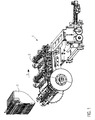
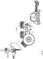
- FIG. 1 shows an oblique view of a preferred embodiment of a device 1 for the transfer of foil bags 2 and FIG. 2 shows a side view of this embodiment.
- the film bags are rectangular flat plastic bags that are open on one side (the top) and closed on all other sides.
- the top side opposite side of the foil bag is referred to as the bottom.
- the open top points in the transport up, the ground down. It should be noted here that the foil bag can be folded in the bottom area in such a way that when the foil bag unfolds, a floor is produced.
- the figure shows a magazine system with juxtaposed foil bag magazines in the form of magazine shafts 3.
- foil bags are stacked from above into the magazine shafts and removed below.
- the step in which the foil bags are transferred from the foil bag magazines to the bag receptacles comprises that a foil bag is transferred to each bag receptacle from all the magazine wells at the same time.
- the transfer is done by machine, for example by means of a suction mechanism not shown here.
- the simultaneously loaded bag receivers form a row of juxtaposed bag receivers.
- the stocked bag receivers are synchronously moved in the transport direction 5 side by side. That is, the row of bag receptacles is arranged perpendicular to the transport direction.
- the bag receivers can thus simultaneously transport juxtaposed foil bags.
- the bag receivers comprise holding elements 6.
- Each holding element comprises a clamp 6a and a side support element 6b with a receptacle.
- the recording can, for example, as here, a slot-shaped, up, down and to the foil bags out be open leadership.
- the guide may, as shown here, have slanted walls or alternatively parallel walls.
- the film bags are inserted from above into the guides and are then laterally supported therein.
- the recordings are designed in such a way that the foil bags are not gripped. By the shots, a lateral movement of the foil bag and in this example, a movement in or against the transport direction is limited.
- the recordings are designed such that a height adjustment of the film bag, ie a movement up or down, is possible.
- the recordings do not pinch the foil bag, so that the bags can be easily inserted into.
- this is achieved by having the guides open at the bottom and top.
- the clips are arranged and configured to grip the foil bags laterally at their upper ends.
- a foil bag is preferably gripped on each side by a clamp.
- the distances between the Garelmente are adjustable and are adjusted according to the width of each processed foil bag.
- the foil bags When transferring from the foil bag magazines, the foil bags are flat and thus have their maximum width.
- the holding elements are arranged at this time at a distance which corresponds approximately to the maximum width, so that the film bag can be easily inserted into the bag receptacles and safely supported in this side.
- the device is designed so that the distances between the holding elements are adjustable relative to each other by means of an adjusting device.
- the distance of the holding elements can be reduced. This allows the foil pouches to be opened at their top, for example, to fill a liquid. If the distance at the time of staple access is minimally smaller than the bag width, maximum stapling engagement can be guaranteed.
- the film bags are transported in the bag receivers and at a certain position, one or more clips 6a each grip a foil bag.
- the brackets grip the foil bag in this case laterally at their upper ends.
- the brackets are designed so that they can transport the foil bag hanging. This means that the gripping force of the clamps is sufficient to hold the foil pouch securely and to prevent it from falling down.
- the foil pouches are then transported further by means of the clamps.
- height-adjustable floor support elements 8 which are designed and arranged such that, in use, they respectively support the bottom of a film bag in a bag receptacle up to the position at which the clips grip the film bag. support from below.
- the ground support elements run synchronously with the bag receptacles during operation. The synchronous movement is achieved here by a mechanical coupling, but can alternatively be done by their own drives, which are controlled by a control device.
- the ground support elements are transported back to the starting position after the gripping of the corresponding foil bag by the brackets, at which the transfer of foil bags takes place in the bag receptacles.
- the floor support elements are arranged here circumferentially about a pivot arm 9.
- the support hooks run around the pivot arm in the direction indicated by the reference numeral 10.
- the floor support elements run by way of example by means of a chain 9a driven about the pivot arm.
- the ground support elements are designed here in the form of support hooks.
- it can be metal rods which have a kink, in this example a kink of about 90 °. Other angles are possible and the hooks can also be composed of several metal bars.
- the hooks have a portion which is arranged substantially perpendicular to the surface of the pivot arm and a portion which points in the transport direction during the support of the film bag from below, in this example, is arranged substantially parallel to the transport direction.
- the support hook and other floor support elements may be provided. When the bottom support members are made wide, tilting of the containers can be avoided.
- the support hooks are arranged side by side in a row along a crossbar and formed integrally therewith. Alternatively, they can also be attached to this or be movable along this crossbar.
- the distance of the support hooks is fixed. If the support hooks are movable along the crossbar, the distance can be adjusted by means of an adjustment unit, in particular automatically. This can be done before starting the operation or during operation.
- each foil bag is assigned at least one support hook. If exactly one support hook is assigned to each foil bag, it is preferable if the support hook is arranged approximately centrally with respect to the bottom of the foil bag. In this case a number of support hooks are about the same distance as the foil bags in this row. If two support hooks are provided for a foil bag, they can each be arranged between the center of the bottom of the film bag and an outer edge of the bottom on different sides of the center.
- the distances of the support hooks can be adjusted together with the distances of the holding elements of the bag receptacles by the same adjusting unit is used for adjusting or by an adjusting unit for the holding elements is coupled to an adjustment for the support elements.
- separate adjusting units can be provided for the holding elements and for the support hooks and the respective positions can be controlled by means of a common control device 12.
- FIG. 3 shows an oblique view from above of the bag receptacles with the holding elements 6.
- the brackets 6b are operated.
- These transverse rods are arranged so that they are rotatable about their longitudinal axis, wherein the brackets are actuated by rotating these rods.
- the holding elements 6 are mounted on slidable tubes, the tube 11e and a corresponding tube (not visible in the figure).
- the tube 11e is connected to the rod 11d and the corresponding invisible tube to the rod 11c. If one of the rods 11c or 11d is displaced transversely to the transport direction (or both relative to one another), the distances of the holding elements and thus also the width of the bag receivers change.
- the pipe 11e and the corresponding non-visible pipe each serve to support the rods 11a and 11d.
- suitable known adjusting devices may be used.
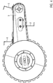
- FIG. 4 shows a side view of a pivot arm and revolving floor support elements that can be used in the first embodiment
- FIG. 5 shows an oblique view from above of the pivot arm and the rotating floor support elements.
- the bottom support elements are designed in the form of support hooks, but it can also be used other bottom support elements, for example, in FIGS. 6b and 6c shown.
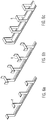
- FIGS. 6a to 6c show different variants, as the ground support elements may be formed in the above examples.
- FIG. 6a shows floor support elements in the form of hooks.
- FIG. 6b shows ground support elements in the form of a support fork and
- FIG. 6c shows floor support elements in the form of support arch.
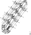
- FIG. 7 Possible arrangements of the floor support elements in a view from below are described in detail in FIG FIG. 7 shown. As shown in the figure, one support hook per foil bag can be centered be arranged under the foil bag. These support hooks can be so wide that they extend to below the brackets. This prevents tilting of the foil bag.
- two support hooks per foil bag can be arranged decentrally under the foil bag or a support fork can be arranged approximately centrally under the foil pouch.
- a support fork allows a better stabilization of the foil bag.
- the support fork can be made wider for further stabilization or it can be provided two decentralized support forks (not shown here).
- All floor support elements can in principle also be formed from round bars, which is shown in the figure only for a single central support hook, but is also applicable to differently arranged and formed floor support elements. It should be noted that various embodiments are shown here by way of example in a figure, but that typically all floor support elements are identical. This is indicated by the dividing lines.
Landscapes
- Engineering & Computer Science (AREA)
- Mechanical Engineering (AREA)
- Supplying Of Containers To The Packaging Station (AREA)
Description
- Die Erfindung betrifft eine Vorrichtung zur Übergabe von Folienbeuteln umfassend ein Magazinsystem mit mehreren nebeneinander angeordneten Folienbeutelmagazinen, mehrere nebeneinander angeordnete Beutelaufnahmen zum gleichzeitigen Transportieren von nebeneinander angeordneten Folienbeuteln, wobei jede Beutelaufnahme zum seitlichen Stützen und Halten eines der Folienbeutel ausgebildet ist und Klammern umfasst, die jeweils zum Greifen eines Folienbeutels in einer Beutelaufnahme und zum hängenden Transportieren des Folienbeutels ausgebildet sind, wobei die Vorrichtung derart ausgebildet ist, dass im Betrieb Folienbeutel aus den Folienbeutelmagazinen an die Beutelaufnahmen übergeben und in den Beutelaufnahmen durch die Klammer gegriffen und hängend transportiert werden.
- Bislang werden zur Übergabe der Folienbeutel Aufnahmekästen verwendet, die jeweils einen fest zugeordneten Boden aufweisen. Der Boden stützt den Boden des Folienbeutels beim Transport. Dieses System hat jedoch verschiedene Nachteile. Zum einen haben die Aufnahmekästen eine große Masse, was insgesamt den Energieverbrauch negativ beeinflusst. Zum anderen sind diese Aufnahmekästen mit Boden jeweils nur für Folienbeutel einer Längenstreckung (bzw. Höhe) geeignet. Die Folienbeutel werden jedoch auf einer festen Höhe von den Klammern gegriffen. Beutel, die kürzer sind müssen daher in einem Aufnahmekasten mit einem höheren Boden transportiert werden, der sie auf die geeignete Höhe bringt. Das heißt, dass ein Formatwechsel erfordert, dass der Aufnahmekasten ausgetauscht oder jeder Boden einzeln verstellt wird.
- Eine Aufgabe der Erfindung ist, die oben genannten Nachteile zu beseitigen, insbesondere eine Vorrichtung bereitzustellen, bei der der Energieverbrauch gesenkt und der Formatwechsel vereinfacht wird.
- Die Aufgabe wird dadurch gelöst, dass die Vorrichtung höhenverstellbare Bodenstützelemente umfasst, die derart ausgebildet und angeordnet sind, dass sie jeweils den Boden eines Folienbeutels in einer Beutelaufnahme bis zu der Position, an der die Klammern den Folienbeutel greifen, von unten stützen.
- Mit der erfindungsgemäßen Vorrichtung können also Beutelaufnahmen ohne Boden verwendet werden, da kein Boden mehr notwendig ist, wenn die Klammern den Folienbeutel greifen. Dies senkt den Energieverbrauch, weil die Beutelaufnahmen eine geringere Masse aufweisen. Außerdem kann die Beutelaufnahme selbst unverändert bleiben, wenn ein Formatwechsel erfolgt, da es ausreicht, die Bodenstützelemente unabhängig von den Beutelaufnahmen zu verstellen. Somit wird der Formatwechsel vereinfacht.
- Folienbeutel sind derart ausgebildet, beispielsweise aus mehreren Folien zusammen geschweißt, dass sie einen Hohlraum einschließen, der an einer Seite offen ist. Die offene Seite wird zum Befüllen der Folienbeutel, beispielsweise mit einem Flüssigen Produkt, verwendet. Im Folgenden wird diese Seite als oberes Ende des Folienbeutels bezeichnet. Die Klammern greifen die Folienbeutel seitlich an ihren oberen Enden. Die der offenen Seite gegenüberliegende Seite des Folienbeutels wird als Boden bezeichnet. In vielen Fällen sind die Folienbeutel flach, wenn sie an die Beutelaufnahme übergeben werden. In den Beutelaufnahmen weisen dann die größeren der Seitenflächen der Folienbeutel in bzw. gegen die Transportrichtung und die schmalen Seiten der Folienbeutel werden seitlich durch die Beutelaufnahme gestützt.
- Eine Beutelaufnahme weist mindestens zwei gegenüberliegende Halteelemente auf, zwischen denen der Folienbeutel eingesetzt wird. Ein Halteelement kann beispielsweise ein Seitenstützelement umfassen, das derart ausgebildet ist, dass es die Seiten der Folienbeutel seitlich stützt. Zusätzlich kann jedes Halteelement eine der Klammern umfassen.
- Die Seitenstützelemente können jeweils eine Aufnahme zum Aufnehmen je einer Seite eines Folienbeutels umfassen, wobei die Halteelemente im Betrieb derart angeordnet sind, dass die Aufnahmen der gegenüberliegenden Seitenstützelemente einen Beutel seitlich stützen. Diese Aufnahmen können insbesondere zum Aufnehmen der oben beschriebenen schmalen Seiten der flachen Folienbeutel ausgebildet sein.
- Die Halteelemente sind quer zur Transportrichtung gegeneinander verschiebbar. So können sie an die Breite des jeweiligen Beutelformats angepasst werden. Außerdem kann die Öffnung des Folienbeutels vergrößert werden, indem die Halteelemente aufeinander zubewegt werden.
- Details zu den Halteelementen, insbesondere den Seitenwänden, den Klammern und der Breitenverstellung können der
EP 2 113 462 A1 entnommen werden. - Die Beutelaufnahme kann nach unten und nach oben offen sein. Das heißt, die Beutelaufnahme hat nur seitliche Begrenzungen bzw. nur Halteelemente. Die Bodenstützelemente können so von unten die seitlich gestützten Folienbeutel stützen, indem sie tiefer als die Halteelemente und direkt unter den Folienbeuteln angeordnet werden oder indem sie direkt unter den Folienbeuteln angeordnet werden und von unten in die Beutelaufnahme hineinragen. Das heißt, dass die Bodenstützelemente zwischen den Halteelementen angeordnet sein können, solange sie den Folienbeutel stützen.
- Die Aufnahmen sind insbesondere derart ausgebildet, dass eine Höhenverstellung der Folienbeutel durch die Aufnahmen nicht beschränkt wird. Die Aufnahmen ermöglichen also eine freie Bewegung der Folienbeutel nach oben oder unten.
- Die Bodenstützelemente können jeweils einen oder mehrere Stäbe umfassen, wobei ein Teil des Stabs bzw. der Stäbe den Folienbeutel von unten stützt. Die Bodenstützelemente können insbesondere in Form von Stützhaken ausgebildet sein. Die Stützhaken können beispielsweise aus einem Stab bestehen, der einen Knick, insbesondere einen Knick von 80° bis 100°, insbesondere von 85° bis 95°, insbesondere von 90°, aufweist. Alternativ können die Stützhaken aus zwei Stäben bestehen, die in einem Winkel von 80° bis 100°, insbesondere von 85° bis 95°, insbesondere von 90°, aneinander befestigt, beispielsweise angeschweißt, sind. Solche Stützhaken können im Betrieb derart angeordnet sein, dass das Ende eines Stützhakens, welches die Folienbeutel stützt, in Transportrichtung weist, insbesondere parallel zur Transportrichtung angeordnet ist. Alternativ können die Bodenstützelemente in Form von Stützgabeln oder Stützbogen ausgebildet sein.
- Die Bodenstützelemente können untereinander mechanisch gekoppelt sein. Die mechanische Koppelung kann derart ausgebildet sein, dass die relative Position der Bodenstützelemente fest ist oder dass die relative Position der Bodenstützelemente verstellbar ist, wobei im Betrieb die Bodenstützelemente in ihrer Position arretiert sind. Die relative Position der Bodenstützelemente kann alternativ auch mittels einer Steuereinrichtung steuerbar sein.
- Die Vorrichtung kann derart ausgebildet sein, dass die Bodenstützelemente im Betrieb bis zu der Position, an der die Klammern den Folienbeutel greifen, synchron und parallel mit den Beutelaufnahmen mit bewegt werden. Die Bodenstützelemente werden also mit den Folienbeuteln mitgeführt. Sie halten die Folienbeutel in einer Position, insbesondere auf der richtigen Höhe, in den Beutelaufnahmen, in der die Klammern die Folienbeutel greifen können. Das Mitführen bzw. die synchrone Bewegung kann mittels mechanischer Koppelung oder mittels einem zusätzlichen Antrieb und optional einer entsprechenden Steuereinrichtung erfolgen.
- Weiterhin kann die Vorrichtung derart ausgebildet sein, dass die Bodenstützelemente, nachdem die Folienbeutel von den Klammern gegriffen wurden in eine Ausgangsposition zurück bewegt werden. Insbesondere werden die Bodenstützelemente unmittelbar nachdem die Folienbeutel von den Klammern gegriffen wurden in die Ausgangsposition zurück bewegt, insbesondere während die Folienbeutel noch in der jeweiligen Beutelaufnahme verbleiben. Die Ausgangsposition ist dabei die Position, in der das Bodenstützelement beginnt einen Folienbeutel von unten zu stützen, wenn er aus einem Folienbeutelmagazin an eine Beutelaufnahme übergeben wird. So kann jedes Bodenstützelement, sobald die Stützfunktion nicht mehr benötigt wird zum Stützen von nachkommenden Folienbeuteln verwendet werden. Insbesondere können die Bodenstützelemente in der Vorrichtung umlaufend angeordnet sein.
- Die Bodenstützelemente können entlang eines höhenverstellbaren Arms, insbesondere Schwenkarms, bewegbar angeordnet sein, insbesondere um den Arm umlaufend. Der Arm kann im Betrieb an einem Ende fest angeordnet sein und an einem Ende höhenverstellbar sein. Der Arm ist also schwenkbar. Ein solcher Arm wird als Schwenkarm bezeichnet. Alternativ können beide Enden des Arms höhenverstellbar sein, beispielsweise mittels eines Hebemechanismus.
- Die Vorrichtung kann derart ausgebildet sein, dass eine Höhenverstellung aller Bodenstützelemente synchron erfolgt, insbesondere mittels mechanischer Koppelung. Insbesondere können die Bodenstützelemente derart angeordnet sein, dass bei der Höhenverstellung des Arms die Bodenstützelemente ebenfalls, insbesondere ohne maschinelle oder manuelle Eingriffe, höhenverstellt werden. Die Vorrichtung kann also derart ausgebildet sein, dass durch eine Höhenverstellung des Arms die Vorrichtung an unterschiedliche Beutellängen angepasst wird.
- Zum Anheben und Absenken des Arms kann eine Verstelleinheit vorgesehen sein. Die Vorrichtung kann also eine Verstelleinheit zur Höhenverstellung des Arms umfassen. Die Verstelleinheit kann insbesondere in Form einer Verstelleinheit zur maschinellen Höhenverstellung des Arms ausgebildet sein. Die Verstelleinheit kann zusätzlich zur Abstandsverstellung gegenüberliegender Halteelemente der Beutelaufnahmen ausgebildet sein.
- Die Vorrichtung kann eine Steuereinheit umfassen, die für die Steuerung einer oder mehrerer der folgenden Schritte ausgebildet ist: die Abstandsverstellung der Halteelemente der Beutelaufnahmen, die Höhenverstellung der Bodenstützelemente bzw. des Arms und/oder die synchrone Bewegung der Bodenstützelemente.
- Weitere Merkmale und Vorteile werden nachfolgend anhand der beispielhaften Figuren erläutert. Dabei zeigt:
-
Figur 1 eine schematische, nicht maßstabsgetreue Schrägansicht auf die Vorrichtung gemäß einer bevorzugten Ausführungsform, -
Figur 2 eine schematische, nicht maßstabsgetreue Seitenansicht auf die Vorrichtung der bevorzugten Ausführungsform, -
Figur 3 eine schematische, nicht maßstabsgetreue Schrägansicht auf zwei Reihen von Beutelaufnahmen, -
Figur 4 eine schematische, nicht maßstabsgetreue Seitenansicht eines Schwenkarms und umlaufender Stützhaken, -
Figur 5 eine schematische, nicht maßstabsgetreue Schrägansicht des Schwenkarms mit umlaufenden Stützhaken, -
Figuren 6a bis 6c schematische, nicht maßstabsgetreue Schrägansichten verschiedener Bodenstützelemente und -
Figur 7 eine schematische, nicht maßstabsgetreue Darstellung verschiedener Anordnungen der Bodenstützelemente unterhalb des Bodens. -
Figur 1 zeigt eine Schrägansicht auf eine bevorzugte Ausführungsform einer Vorrichtung 1 zur Übergabe von Folienbeuteln 2 undFigur 2 zeigt eine Seitenansicht dieser Ausführungsform. Bei den Folienbeuteln handelt es sich um im flachen Zustand rechteckige Folienbeutel, die an einer Seite (der Oberseite) offen und an allen anderen Seiten verschlossen sind. Die der Oberseite gegenüberliegende Seite der Folienbeutel wird als Boden bezeichnet. Die offene Oberseite weist im Transport nach oben, der Boden nach unten. Hier sei angemerkt, dass der Folienbeutel im Bodenbereich derart gefaltet sein kann, dass bei einem Auffalten des Folienbeutels ein Standboden entsteht. - Die Figur zeigt ein Magazinsystem mit nebeneinander angeordneten Folienbeutelmagazinen in Form von Magazinschächten 3. Im Betrieb werden Folienbeutel von oben in die Magazinschächte gestapelt und unten entnommen. Der Schritt, in dem die Folienbeutel aus den Folienbeutelmagazinen an die Beutelaufnahmen übergeben werden, umfasst, dass aus allen Magazinschächten gleichzeitig je ein Folienbeutel an je eine Beutelaufnahme übergeben wird. Das Übergeben erfolgt maschinell, beispielsweise mittels eines hier nicht gezeigten Saugmechanismus. Die gleichzeitig bestückten Beutelaufnahmen bilden eine Reihe nebeneinander angeordneter Beutelaufnahmen. Die bestückten Beutelaufnahmen werden nebeneinander synchron in Transportrichtung 5 bewegt. Das heißt, die Reihe von Beutelaufnahmen ist senkrecht zur Transportrichtung angeordnet. Die Beutelaufnahmen können somit gleichzeitig nebeneinander angeordnete Folienbeutel transportieren.
- Die Beutelaufnahmen umfassen Halteelemente 6. Jedes Halteelement umfasst eine Klammer 6a und ein Seitenstützelement 6b mit einer Aufnahme. Die Aufnahme kann beispielsweise, wie hier, eine schlitzförmige, nach oben, unten und zu den Folienbeuteln hin offene Führung sein. Die Führung kann, wie hier gezeigt, abgeschrägte Wände oder alternativ parallel stehende Wände aufweisen. Im Betrieb werden die Folienbeutel von oben in die Führungen eingeführt und sind dann darin seitlich gestützt. Die Aufnahmen sind derart ausgebildet, dass die Folienbeutel nicht gegriffen werden. Durch die Aufnahmen wird eine seitliche Bewegung der Folienbeutel und in diesem Beispiel auch eine Bewegung in bzw. gegen die Transportrichtung beschränkt. Die Aufnahmen sind derart ausgebildet, dass eine Höhenverstellung der Folienbeutel, also eine Bewegung nach oben oder unten, möglich ist. Dies wird ermöglicht, indem die Aufnahmen die Folienbeutel nicht einklemmen, so dass die Beutel problemlos in eingesetzt werden können. In diesem Beispiel wird das erreicht, indem die Führungen unten und oben offen sind. Die Klammern sind derart angeordnet und ausgebildet, dass sie die Folienbeutel seitlich an ihren oberen Enden greifen. Ein Folienbeutel wird dabei vorzugsweise auf jeder Seite von einer Klammer gegriffen.
- Die Abstände der Halteelmente sind verstellbar und werden entsprechend der Breite der jeweils verarbeiteten Folienbeutel eingestellt. Bei der Übergabe aus den Folienbeutelmagazinen sind die Folienbeutel flach und haben somit ihre maximale Breite. Die Halteelemente sind zu diesem Zeitpunkt in einem Abstand angeordnet, der etwa der maximalen Breite entspricht, so dass die Folienbeutel problemlos in die Beutelaufnahmen eingeführt und in diesen sicher seitlich gestützt werden können.
- Die Vorrichtung ist so ausgebildet, dass die Abstände der Halteelemente zueinander mittels einer Verstelleinrichtung verstellbar sind. Auf dem Transportweg der Beutel in den Aufnahmekästen kann optional der Abstand der Halteelemente reduziert werden. Dadurch können die Folienbeutel an ihrer Oberseite geöffnet werden, zum Beispiel, um eine Flüssigkeit einzufüllen. Wenn der Abstand zum Zeitpunkt des Klammerzugriffs minimal kleiner ausfällt als die Beutelbreite kann ein maximaler Klammereingriff garantiert werden.
- Die Folienbeutel werden in den Beutelaufnahmen transportiert und an einer bestimmten Position greifen eine oder mehrere Klammern 6a jeweils einen Folienbeutel. Die Klammern greifen den Folienbeutel in diesem Fall seitlich an ihren oberen Enden. Die Klammern sind derart ausgebildet, dass sie den Folienbeutel hängend transportieren können. Das heißt, dass die Greifkraft der Klammern ausreicht, um den Folienbeutel sicher zu halten und ein Herabfallen zu vermeiden. Die Folienbeutel werden dann mittels der Klammern weiter transportiert.
- In den Figuren sind ebenfalls höhenverstellbare Bodenstützelemente 8 gezeigt, die derart ausgebildet und angeordnet sind, dass sie im Betrieb jeweils den Boden eines Folienbeutels in einer Beutelaufnahme bis zu der Position, an der die Klammern den Folienbeutel greifen, von unten stützen. Dazu laufen die Bodenstützelemente im Betrieb synchron mit den Beutelaufnahmen mit. Die synchrone Bewegung wird hier durch eine mechanische Koppelung erzielt, kann aber alternativ auch durch eigene Antriebe erfolgen, die mittels einer Steuereinrichtung gesteuert werden.
- Die Bodenstützelemente werden nach dem Greifen der entsprechenden Folienbeutel durch die Klammern wieder zurück in die Ausgangsposition transportiert, an der die Übergabe von Folienbeuteln in die Beutelaufnahmen erfolgt. Die Bodenstützelemente sind hier umlaufend um einen Schwenkarm 9 angeordnet. Im Betrieb laufen die Stützhaken um den Schwenkarm in der mit dem Bezugszeichen 10 gekennzeichneten Richtung. Hier laufen die Bodenstützelemente beispielhaft mittels einer Kette 9a angetrieben um den Schwenkarm.
- Die Bodenstützelemente sind hier in Form von Stützhaken ausgebildet. Beispielsweise kann es sich um Metallstäbe handeln, die einen Knick, in diesem Beispiel einen Knick von etwa 90°, aufweisen. Andere Winkel sind möglich und die Haken können auch aus mehreren Metallstäben zusammengesetzt sein. Wie hier zu erkennen ist, haben die Haken einen Teilbereich, der im Wesentlichen senkrecht zu der Oberfläche des Schwenkarms angeordnet ist und einen Teilbereich, der während dem Stützen der Folienbeutel von unten in Transportrichtung weist, in diesem Beispiel im Wesentlichen parallel zur Transportrichtung angeordnet ist. Statt der Stützhaken können auch andere Bodenstützelemente vorgesehen sein. Wenn die Bodenstützelemente breit ausgebildet sind, kann ein Kippen bzw. Schrägstehen der Behälter vermieden werden.
- In dem gezeigten Beispiel sind die Stützhaken nebeneinander in einer Reihe entlang einer Querstange angeordnet und mit dieser integral ausgebildet. Alternativ können sie auch an dieser befestigt sein oder entlang dieser Querstange verfahrbar sein.
- Wenn die Stützhaken und die Querstange integral ausgebildet sind, ist der Abstand der Stützhaken fest. Wenn die Stützhaken entlang der Querstange verfahrbar sind, kann der Abstand mittels einer Verstelleinheit, insbesondere automatisch, eingestellt werden. Dies kann vor der Aufnahme des Betriebs oder im Betrieb erfolgen.
- Die Abstände der Stützhaken sind oder werden im Betrieb derart eingestellt, dass sichergestellt wird, dass jedem Folienbeutel mindestens ein Stützhaken zugeordnet ist. Wenn jedem Folienbeutel genau ein Stützhaken zugeordnet ist, ist es vorzuziehen, wenn der Stützhaken bezogen auf den Boden des Folienbeutels etwa mittig angeordnet ist. In diesem Fall hat eine Reihe von Stützhaken etwa den gleichen Abstand wie die Folienbeutel in dieser Reihe. Wenn für einen Folienbeutel zwei Stützhaken vorgesehen sind, können diese jeweils zwischen der Mitte des Bodens des Folienbeutels und einem äußeren Rand des Bodens auf verschiedenen Seiten der Mitte angeordnet sein.
- Optional können die Abstände der Stützhaken zusammen mit den Abständen der Halteelemente der Beutelaufnahmen verstellbar sein, indem die gleiche Verstelleinheit zum Verstellen verwendet wird oder indem eine Verstelleinheit für die Halteelemente mit einer Verstelleinheit für die Stützelemente gekoppelt wird. Alternativ können für die Halteelemente und für die Stützhaken separate Verstelleinheiten vorgesehen sein und die jeweiligen Positionen mittels einer gemeinsamen Steuereinrichtung 12 gesteuert werden.
-
Figur 3 zeigt einen in Schrägansicht von oben auf die Beutelaufnahmen mit den Halteelementen 6. Mit Hilfe der Querstangen 11a und 11b werden die Klammern 6b betätigt. Diese Querstangen sind so angeordnet, dass sie um ihre Längsachse drehbar sind, wobei durch Drehen dieser Stangen die Klammern betätigt werden. Die Halteelemente 6 sind auf verschiebbaren Rohren, dem Rohr 11e und einem entsprechenden (in der Figur nicht sichtbaren) Rohr, befestigt. Das Rohr 11e ist mit der Stange 11d verbunden und das entsprechende nicht sichtbare Rohr mit der Stange 11c. Wird eine der Stangen 11c oder 11d quer zur Transportrichtung verschoben (oder beide relativ zueinander), ändern sich die Abstände der Halteelemte und somit auch die Breite der Beutelaufnahmen. Zusätzlich dienen das Rohr 11e und das entsprechende nicht sichtbare Rohr jeweils als Lagerung der Stangen 11a und 11d. Als Verstelleinrichtungen zum Verstellen der Abstände der Halteelemente in derartigen Vorrichtungen und als Betätigungsmechanismen für die Klammern können geeignete bekannte Verstelleinrichtungen verwendet werden. Hier sei beispielhaft auf die oben genannte DruckschriftEP 2 113 462 A1 verwiesen. -
Figur 4 zeigt eine Seitenansicht von einem Schwenkarm und umlaufenden Bodenstützelementen, die in der erstem Ausführungsform verwendet werden können, undFigur 5 zeigt eine Schrägansicht von oben auf den Schwenkarm und die umlaufenden Bodenstützelemente. Hier sind die Bodenstützelemente in Form von Stützhaken ausgebildet, es können jedoch auch andere Bodenstützelemente verwendet werden, beispielsweise die inFigur 6b und 6c gezeigten. -
Figuren 6a bis 6c zeigen verschiedene Varianten, wie die Bodenstützelemente in den oben genannten Beispielen ausgebildet sein können.Figur 6a zeigt Bodenstützelemente in Form von Haken.Figur 6b zeigt Bodenstützelemente in Form einer Stützgabel undFigur 6c zeigt Bodenstützelemente in Form von Stützbogen. - Mögliche Anordnungen der Bodenstützelemente in einer Ansicht von unten sind im Detail in
Figur 7 gezeigt. Wie in der Figur gezeigt, kann jeweils ein Stützhaken pro Folienbeutel mittig unter dem Folienbeutel angeordnet sein. Diese Stützhaken können so breit sein, dass sie sich bis unterhalb der Klammern erstrecken. Dies verhindert ein Kippen der Folienbeutel. - Alternativ können zwei Stützhaken pro Folienbeutel dezentral unter dem Folienbeutel angeordnet sein oder eine Stützgabel kann etwa mittig unter dem Folienbeutel angeordnet sein. Eine Stützgabel ermöglicht eine bessere Stabilisierung der Folienbeutel. Auch die Stützgabel kann zur weiteren Stabilisierung breiter ausgebildet sein oder es können zwei dezentrale Stützgabeln vorgesehen sein (hier nicht gezeigt). Alle Bodenstützelemente können im Prinzip auch aus Rundstäben ausgebildet ist, was in der Figur nur für einen einzelnen mittigen Stützhaken gezeigt ist, aber auch für anders angeordnete und ausgebildete Bodenstützelemente anwendbar ist. Es sei angemerkt, dass hier beispielhaft verschiedene Ausführungen in einer Figur gezeigt sind, dass jedoch typischerweise alle Bodenstützelemente gleich ausgebildet sind. Dies ist durch die Trennlinien angedeutet.
- Es versteht sich, dass in den zuvor beschriebenen Ausführungsbeispielen genannte Merkmale nicht auf diese speziellen Kombinationen beschränkt sind und auch in beliebigen anderen Kombinationen möglich sind.
Claims (14)
- Vorrichtung (1) zur Übergabe von Folienbeuteln (2) umfassend
ein Magazinsystem mit mehreren nebeneinander angeordneten Folienbeutelmagazinen (3),
mehrere nebeneinander angeordnete Beutelaufnahmen zum gleichzeitigen Transportieren von nebeneinander angeordneten Folienbeuteln (2), wobei jede Beutelaufnahme zum seitlichen Stützen und Halten eines der Folienbeutel (2) ausgebildet ist und Klammern (6a) umfasst, die jeweils zum Greifen eines Folienbeutels (2) in einer Beutelaufnahme und zum hängenden Transportieren des Folienbeutels (2) ausgebildet sind,
wobei die Vorrichtung derart ausgebildet ist, dass im Betrieb Folienbeutel (2) aus den Folienbeutelmagazinen (3) an die Beutelaufnahmen übergeben und in den Beutelaufnahmen durch die Klammern (6a) gegriffen und hängend transportiert werden,
gekennzeichnet durch
höhenverstellbare Bodenstützelemente (8), die derart ausgebildet und angeordnet sind, dass sie jeweils den Boden eines Folienbeutels (2) in einer Beutelaufnahme bis zu der Position, an der die Klammern (6a) den Folienbeutel (2) greifen, von unten stützen,
wobei die Bodenstützelemente (8) umlaufend angeordnet sind. - Vorrichtung nach Anspruch 1, wobei die Beutelaufnahme nach unten und nach oben offen ist.
- Vorrichtung nach Anspruch 1 oder 2, wobei die Bodenstützelemente (8) in der Vorrichtung in Form von Stützhaken ausgebildet sind.
- Vorrichtung nach einem der Ansprüche 1 bis 3, wobei die Vorrichtung derart ausgebildet ist, dass die Bodenstützelemente (8) im Betrieb bis zu der Position, an der die Klammern (6a) den Folienbeutel (2) greifen, synchron und parallel mit den Beutelaufnahmen mit bewegt werden.
- Vorrichtung nach Anspruch 4, wobei die synchrone Bewegung mittels mechanischer Koppelung oder mittels einer Steuereinrichtung und einem zusätzlichen Antrieb erfolgt.
- Vorrichtung nach einem der Ansprüche 1 bis 5, wobei die Vorrichtung derart ausgebildet ist, dass die Bodenstützelemente (8), nachdem der von ihnen gestützte Folienbeutel (2) von den Klammern (6a) gegriffen wurde, in eine Ausgangsposition zurück bewegt werden.
- Vorrichtung nach einem der Ansprüche 1 bis 6, wobei die Bodenstützelemente (8) in der Vorrichtung entlang eines höhenverstellbaren Arms (9) bewegbar angeordnet sind.
- Vorrichtung nach Anspruch 7, wobei die Vorrichtung derart ausgebildet ist, dass die Bodenstützelemente (8) um den höhenverstellbaren Arm (9) umlaufend angeordnet sind.
- Vorrichtung nach einem der Ansprüche 1 bis 8, wobei die Vorrichtung derart ausgebildet ist, dass eine Höhenverstellung aller Bodenstützelemente (8) synchron erfolgt, insbesondere mittels mechanischer Koppelung.
- Vorrichtung nach Anspruch 7 bis 9, wobei die Bodenstützelemente (8) derart angeordnet sind, dass durch eine Höhenverstellung des Arms (9) die Bodenstützelemente (8) ebenfalls höhenverstellt werden.
- Vorrichtung nach einem der Ansprüche 7 bis 10, wobei durch eine Höhenverstellung des Arms (9) die Vorrichtung an unterschiedliche Beutellängen angepasst wird.
- Vorrichtung nach einem der Ansprüche 7 bis 11, wobei zum Anheben und Absenken des Arms (9) eine Verstelleinheit vorgesehen ist.
- Vorrichtung nach Anspruch 12, wobei die Verstelleinheit zusätzlich zur Abstandsverstellung gegenüberliegender Halteelemente (6) der Beutelaufnahmen ausgebildet ist.
- Vorrichtung nach einem der Ansprüche 7 bis 13, wobei ein bzw. der zusätzliche Antrieb die Bodenstützelemente im Betrieb derart antreibt, dass sie um den höhenverstellbaren Arm herum laufen.
Priority Applications (3)
| Application Number | Priority Date | Filing Date | Title |
|---|---|---|---|
| EP16167896.6A EP3241768B1 (de) | 2016-05-02 | 2016-05-02 | Vorrichtung zur übergabe von folienbeuteln |
| ES16167896T ES2704729T3 (es) | 2016-05-02 | 2016-05-02 | Dispositivo para la entrega de bolsas de lámina |
| US15/583,340 US10569916B2 (en) | 2016-05-02 | 2017-05-01 | Apparatus for the transfer of foil bags |
Applications Claiming Priority (1)
| Application Number | Priority Date | Filing Date | Title |
|---|---|---|---|
| EP16167896.6A EP3241768B1 (de) | 2016-05-02 | 2016-05-02 | Vorrichtung zur übergabe von folienbeuteln |
Publications (2)
| Publication Number | Publication Date |
|---|---|
| EP3241768A1 EP3241768A1 (de) | 2017-11-08 |
| EP3241768B1 true EP3241768B1 (de) | 2018-11-14 |
Family
ID=55952987
Family Applications (1)
| Application Number | Title | Priority Date | Filing Date |
|---|---|---|---|
| EP16167896.6A Not-in-force EP3241768B1 (de) | 2016-05-02 | 2016-05-02 | Vorrichtung zur übergabe von folienbeuteln |
Country Status (3)
| Country | Link |
|---|---|
| US (1) | US10569916B2 (de) |
| EP (1) | EP3241768B1 (de) |
| ES (1) | ES2704729T3 (de) |
Families Citing this family (2)
| Publication number | Priority date | Publication date | Assignee | Title |
|---|---|---|---|---|
| IT202000012166A1 (it) * | 2020-05-25 | 2021-11-25 | Perfect Pack S R L | Macchina confezionatrice |
| CN117446271A (zh) * | 2023-11-20 | 2024-01-26 | 瑞安市昂华机械有限公司 | 给袋机的送袋机构 |
Family Cites Families (13)
| Publication number | Priority date | Publication date | Assignee | Title |
|---|---|---|---|---|
| US2654518A (en) * | 1949-04-09 | 1953-10-06 | Bemis Bro Bag Co | Apparatus for filling and compacting material in bags and having a retractable bag bottom abutment member |
| US2721015A (en) * | 1950-05-20 | 1955-10-18 | Dixon Engineering Company | Article bagging machine |
| US4330288A (en) * | 1980-02-07 | 1982-05-18 | Russell Robert C | Packaging machine with pouch transfer and opening mechanism |
| US4456118A (en) * | 1981-11-18 | 1984-06-26 | Ex-Cell-O Corporation | Single to dual indexing carton transfer mechanism |
| US5058364A (en) * | 1990-07-27 | 1991-10-22 | Klockner-Bartelt, Inc. | Packaging machine adapted to convert pouches from edgewise advance to broadwise advance |
| US5443150A (en) * | 1993-09-23 | 1995-08-22 | Rapidpak, Inc. | Apparatus for advancing preformed containers |
| DE19744899A1 (de) * | 1997-10-10 | 1999-04-15 | Indag Gmbh | Verfahren und Vorrichtung zur Behandlung flexibler Beutel |
| US6931824B2 (en) * | 2002-06-07 | 2005-08-23 | Amec E&C Services, Inc. | Packaging system |
| WO2005100163A1 (en) * | 2004-04-15 | 2005-10-27 | Pak Technologies Group Pty Ltd | Pouch filling and sealing line and a magazine for delivering pouches |
| ES2314809T3 (es) * | 2006-11-15 | 2009-03-16 | INDAG GESELLSCHAFT FUR INDUSTRIEBEDARF MBH & CO. BETRIEBS KG | Dispositivo transportador. |
| ITPR20070037A1 (it) * | 2007-05-18 | 2008-11-19 | Wild Parma S R L | Apparato e procedimento per la movimentazione in continuo di contenitori flessibili da una macchina rotativa ad un trasportatore. |
| PL2113462T3 (pl) * | 2008-05-02 | 2011-06-30 | Indag Gesellschaft Fuer Ind Mbh & Co Betriebs Kg | Urządzenie do przenoszenia elastycznych worków |
| US9573716B2 (en) * | 2014-04-04 | 2017-02-21 | Pouch Pac Innovations, Llc | Pouch support device |
-
2016
- 2016-05-02 ES ES16167896T patent/ES2704729T3/es active Active
- 2016-05-02 EP EP16167896.6A patent/EP3241768B1/de not_active Not-in-force
-
2017
- 2017-05-01 US US15/583,340 patent/US10569916B2/en not_active Expired - Fee Related
Non-Patent Citations (1)
| Title |
|---|
| None * |
Also Published As
| Publication number | Publication date |
|---|---|
| ES2704729T3 (es) | 2019-03-19 |
| EP3241768A1 (de) | 2017-11-08 |
| US20170313456A1 (en) | 2017-11-02 |
| US10569916B2 (en) | 2020-02-25 |
Similar Documents
| Publication | Publication Date | Title |
|---|---|---|
| DE69100158T2 (de) | Greif- und Übertragungszange. | |
| EP3241767B1 (de) | Verarbeitungsvorrichtung für folienbeutel | |
| EP0419441B1 (de) | Vorrichtung zum Biegen von Stahlstäben zu Betonbewehrungselementen | |
| AT515385B1 (de) | Verfahren sowie Anlage zum Ablegen von Profilstäben | |
| EP2072430B1 (de) | Paketgreifer für eine Palettiervorrichtung und Verfahren zum Palettieren von Paketen | |
| EP2113462A1 (de) | Vorrichtung zum Handhaben von flexiblen Beuteln | |
| EP2457858A1 (de) | Vorrichtung und Verfahren zum Bilden von Paketen aus Druckproduken | |
| EP2881332A1 (de) | Transportvorrichtung zum Fördern von Produkten | |
| EP1445224B2 (de) | Vorrichtung zum Bilden von Stapeln aus flächigen Gegenständen | |
| EP3241768A1 (de) | Vorrichtung zur übergabe von folienbeuteln | |
| EP2260732A1 (de) | Vorrichtung und Verfahren zum aufeinander folgenden Entleeren von mit stabförmigen Produkten gefüllten Behältern | |
| EP2363344A1 (de) | Vorrichtung und Verfahren zum Verpacken von stapelbaren Gegenständen, insbesondere von Druckereierzeugnissen, sowie Wendeeinrichtung zum Wenden von stapelbaren Erzeugnissen | |
| DE102010047775A1 (de) | Verfahren und Vorrichtung zum Bewegen eines Stapels, vorzugsweise eines Stapels zusammengelegter und gefalteter textiler Gegenstände | |
| DE202012004646U1 (de) | Klammerapparat zum Zuführen von Klammerbündeln | |
| EP0808106B1 (de) | Vorrichtung zum automatischen transport von flächigen teigstückträgern | |
| AT515407A4 (de) | Biegewerkzeug sowie Wechseleinheit hierfür | |
| DE69306657T2 (de) | Verfahren und Vorrichtung zumVerpacken von Ampullen | |
| EP1089932B1 (de) | Anlegevorrichtung | |
| DE1611623C3 (de) | Vorrichtung zur Abführung eines Schachteloberteils oder -Unterteils aus ' einer Maschine. Ausscheidung aus: 1267527 | |
| EP2596708A2 (de) | Handhabungsanordnung für Transportbehältern für stabförmige Artikel der Tabak verarbeitenden Industrie, Umlaufkassette sowie Verfahren zum Verändern des Füllstandes von Transportbehältern | |
| DE2904554A1 (de) | Verfahren zum einlegen von flossenpackungen in einen behaelter und einrichtung zur durchfuehrung des verfahrens | |
| DE102014108732B3 (de) | Vorrichtung zur Handhabung von Blisterverpackungen | |
| EP3127824B1 (de) | Vorrichtung und verfahren zum zuführen von folienbeuteln zu einer füllmaschine | |
| DE29916028U1 (de) | Tray zur Aufnahme und zum Transport von Flaschen | |
| DE19858516C2 (de) | Rollenwickelvorrichtung |
Legal Events
| Date | Code | Title | Description |
|---|---|---|---|
| PUAI | Public reference made under article 153(3) epc to a published international application that has entered the european phase |
Free format text: ORIGINAL CODE: 0009012 |
|
| STAA | Information on the status of an ep patent application or granted ep patent |
Free format text: STATUS: THE APPLICATION HAS BEEN PUBLISHED |
|
| AK | Designated contracting states |
Kind code of ref document: A1 Designated state(s): AL AT BE BG CH CY CZ DE DK EE ES FI FR GB GR HR HU IE IS IT LI LT LU LV MC MK MT NL NO PL PT RO RS SE SI SK SM TR |
|
| AX | Request for extension of the european patent |
Extension state: BA ME |
|
| STAA | Information on the status of an ep patent application or granted ep patent |
Free format text: STATUS: REQUEST FOR EXAMINATION WAS MADE |
|
| 17P | Request for examination filed |
Effective date: 20180327 |
|
| RBV | Designated contracting states (corrected) |
Designated state(s): AL AT BE BG CH CY CZ DE DK EE ES FI FR GB GR HR HU IE IS IT LI LT LU LV MC MK MT NL NO PL PT RO RS SE SI SK SM TR |
|
| GRAP | Despatch of communication of intention to grant a patent |
Free format text: ORIGINAL CODE: EPIDOSNIGR1 |
|
| RIC1 | Information provided on ipc code assigned before grant |
Ipc: B65B 43/46 20060101AFI20180426BHEP Ipc: B65B 43/44 20060101ALI20180426BHEP Ipc: B65B 43/16 20060101ALI20180426BHEP Ipc: B65B 43/28 20060101ALI20180426BHEP Ipc: B65B 59/00 20060101ALI20180426BHEP |
|
| STAA | Information on the status of an ep patent application or granted ep patent |
Free format text: STATUS: GRANT OF PATENT IS INTENDED |
|
| INTG | Intention to grant announced |
Effective date: 20180531 |
|
| RAP1 | Party data changed (applicant data changed or rights of an application transferred) |
Owner name: INDAG POUCH PARTNERS GMBH |
|
| GRAS | Grant fee paid |
Free format text: ORIGINAL CODE: EPIDOSNIGR3 |
|
| GRAA | (expected) grant |
Free format text: ORIGINAL CODE: 0009210 |
|
| STAA | Information on the status of an ep patent application or granted ep patent |
Free format text: STATUS: THE PATENT HAS BEEN GRANTED |
|
| AK | Designated contracting states |
Kind code of ref document: B1 Designated state(s): AL AT BE BG CH CY CZ DE DK EE ES FI FR GB GR HR HU IE IS IT LI LT LU LV MC MK MT NL NO PL PT RO RS SE SI SK SM TR |
|
| REG | Reference to a national code |
Ref country code: CH Ref legal event code: EP Ref country code: AT Ref legal event code: REF Ref document number: 1064513 Country of ref document: AT Kind code of ref document: T Effective date: 20181115 |
|
| REG | Reference to a national code |
Ref country code: DE Ref legal event code: R096 Ref document number: 502016002471 Country of ref document: DE |
|
| REG | Reference to a national code |
Ref country code: IE Ref legal event code: FG4D Free format text: LANGUAGE OF EP DOCUMENT: GERMAN |
|
| REG | Reference to a national code |
Ref country code: ES Ref legal event code: FG2A Ref document number: 2704729 Country of ref document: ES Kind code of ref document: T3 Effective date: 20190319 |
|
| REG | Reference to a national code |
Ref country code: NL Ref legal event code: MP Effective date: 20181114 |
|
| REG | Reference to a national code |
Ref country code: LT Ref legal event code: MG4D |
|
| PG25 | Lapsed in a contracting state [announced via postgrant information from national office to epo] |
Ref country code: LV Free format text: LAPSE BECAUSE OF FAILURE TO SUBMIT A TRANSLATION OF THE DESCRIPTION OR TO PAY THE FEE WITHIN THE PRESCRIBED TIME-LIMIT Effective date: 20181114 Ref country code: LT Free format text: LAPSE BECAUSE OF FAILURE TO SUBMIT A TRANSLATION OF THE DESCRIPTION OR TO PAY THE FEE WITHIN THE PRESCRIBED TIME-LIMIT Effective date: 20181114 Ref country code: BG Free format text: LAPSE BECAUSE OF FAILURE TO SUBMIT A TRANSLATION OF THE DESCRIPTION OR TO PAY THE FEE WITHIN THE PRESCRIBED TIME-LIMIT Effective date: 20190214 Ref country code: HR Free format text: LAPSE BECAUSE OF FAILURE TO SUBMIT A TRANSLATION OF THE DESCRIPTION OR TO PAY THE FEE WITHIN THE PRESCRIBED TIME-LIMIT Effective date: 20181114 Ref country code: IS Free format text: LAPSE BECAUSE OF FAILURE TO SUBMIT A TRANSLATION OF THE DESCRIPTION OR TO PAY THE FEE WITHIN THE PRESCRIBED TIME-LIMIT Effective date: 20190314 Ref country code: FI Free format text: LAPSE BECAUSE OF FAILURE TO SUBMIT A TRANSLATION OF THE DESCRIPTION OR TO PAY THE FEE WITHIN THE PRESCRIBED TIME-LIMIT Effective date: 20181114 Ref country code: NO Free format text: LAPSE BECAUSE OF FAILURE TO SUBMIT A TRANSLATION OF THE DESCRIPTION OR TO PAY THE FEE WITHIN THE PRESCRIBED TIME-LIMIT Effective date: 20190214 |
|
| PG25 | Lapsed in a contracting state [announced via postgrant information from national office to epo] |
Ref country code: GR Free format text: LAPSE BECAUSE OF FAILURE TO SUBMIT A TRANSLATION OF THE DESCRIPTION OR TO PAY THE FEE WITHIN THE PRESCRIBED TIME-LIMIT Effective date: 20190215 Ref country code: RS Free format text: LAPSE BECAUSE OF FAILURE TO SUBMIT A TRANSLATION OF THE DESCRIPTION OR TO PAY THE FEE WITHIN THE PRESCRIBED TIME-LIMIT Effective date: 20181114 Ref country code: NL Free format text: LAPSE BECAUSE OF FAILURE TO SUBMIT A TRANSLATION OF THE DESCRIPTION OR TO PAY THE FEE WITHIN THE PRESCRIBED TIME-LIMIT Effective date: 20181114 Ref country code: PT Free format text: LAPSE BECAUSE OF FAILURE TO SUBMIT A TRANSLATION OF THE DESCRIPTION OR TO PAY THE FEE WITHIN THE PRESCRIBED TIME-LIMIT Effective date: 20190314 Ref country code: AL Free format text: LAPSE BECAUSE OF FAILURE TO SUBMIT A TRANSLATION OF THE DESCRIPTION OR TO PAY THE FEE WITHIN THE PRESCRIBED TIME-LIMIT Effective date: 20181114 Ref country code: SE Free format text: LAPSE BECAUSE OF FAILURE TO SUBMIT A TRANSLATION OF THE DESCRIPTION OR TO PAY THE FEE WITHIN THE PRESCRIBED TIME-LIMIT Effective date: 20181114 |
|
| PG25 | Lapsed in a contracting state [announced via postgrant information from national office to epo] |
Ref country code: DK Free format text: LAPSE BECAUSE OF FAILURE TO SUBMIT A TRANSLATION OF THE DESCRIPTION OR TO PAY THE FEE WITHIN THE PRESCRIBED TIME-LIMIT Effective date: 20181114 Ref country code: CZ Free format text: LAPSE BECAUSE OF FAILURE TO SUBMIT A TRANSLATION OF THE DESCRIPTION OR TO PAY THE FEE WITHIN THE PRESCRIBED TIME-LIMIT Effective date: 20181114 Ref country code: PL Free format text: LAPSE BECAUSE OF FAILURE TO SUBMIT A TRANSLATION OF THE DESCRIPTION OR TO PAY THE FEE WITHIN THE PRESCRIBED TIME-LIMIT Effective date: 20181114 |
|
| REG | Reference to a national code |
Ref country code: DE Ref legal event code: R097 Ref document number: 502016002471 Country of ref document: DE |
|
| PG25 | Lapsed in a contracting state [announced via postgrant information from national office to epo] |
Ref country code: RO Free format text: LAPSE BECAUSE OF FAILURE TO SUBMIT A TRANSLATION OF THE DESCRIPTION OR TO PAY THE FEE WITHIN THE PRESCRIBED TIME-LIMIT Effective date: 20181114 Ref country code: SK Free format text: LAPSE BECAUSE OF FAILURE TO SUBMIT A TRANSLATION OF THE DESCRIPTION OR TO PAY THE FEE WITHIN THE PRESCRIBED TIME-LIMIT Effective date: 20181114 Ref country code: SM Free format text: LAPSE BECAUSE OF FAILURE TO SUBMIT A TRANSLATION OF THE DESCRIPTION OR TO PAY THE FEE WITHIN THE PRESCRIBED TIME-LIMIT Effective date: 20181114 Ref country code: EE Free format text: LAPSE BECAUSE OF FAILURE TO SUBMIT A TRANSLATION OF THE DESCRIPTION OR TO PAY THE FEE WITHIN THE PRESCRIBED TIME-LIMIT Effective date: 20181114 |
|
| PLBE | No opposition filed within time limit |
Free format text: ORIGINAL CODE: 0009261 |
|
| STAA | Information on the status of an ep patent application or granted ep patent |
Free format text: STATUS: NO OPPOSITION FILED WITHIN TIME LIMIT |
|
| 26N | No opposition filed |
Effective date: 20190815 |
|
| PG25 | Lapsed in a contracting state [announced via postgrant information from national office to epo] |
Ref country code: SI Free format text: LAPSE BECAUSE OF FAILURE TO SUBMIT A TRANSLATION OF THE DESCRIPTION OR TO PAY THE FEE WITHIN THE PRESCRIBED TIME-LIMIT Effective date: 20181114 |
|
| REG | Reference to a national code |
Ref country code: CH Ref legal event code: PL |
|
| PG25 | Lapsed in a contracting state [announced via postgrant information from national office to epo] |
Ref country code: CH Free format text: LAPSE BECAUSE OF NON-PAYMENT OF DUE FEES Effective date: 20190531 Ref country code: MC Free format text: LAPSE BECAUSE OF FAILURE TO SUBMIT A TRANSLATION OF THE DESCRIPTION OR TO PAY THE FEE WITHIN THE PRESCRIBED TIME-LIMIT Effective date: 20181114 Ref country code: LI Free format text: LAPSE BECAUSE OF NON-PAYMENT OF DUE FEES Effective date: 20190531 |
|
| REG | Reference to a national code |
Ref country code: BE Ref legal event code: MM Effective date: 20190531 |
|
| PG25 | Lapsed in a contracting state [announced via postgrant information from national office to epo] |
Ref country code: LU Free format text: LAPSE BECAUSE OF NON-PAYMENT OF DUE FEES Effective date: 20190502 |
|
| PG25 | Lapsed in a contracting state [announced via postgrant information from national office to epo] |
Ref country code: TR Free format text: LAPSE BECAUSE OF FAILURE TO SUBMIT A TRANSLATION OF THE DESCRIPTION OR TO PAY THE FEE WITHIN THE PRESCRIBED TIME-LIMIT Effective date: 20181114 |
|
| PG25 | Lapsed in a contracting state [announced via postgrant information from national office to epo] |
Ref country code: IE Free format text: LAPSE BECAUSE OF NON-PAYMENT OF DUE FEES Effective date: 20190502 |
|
| PG25 | Lapsed in a contracting state [announced via postgrant information from national office to epo] |
Ref country code: BE Free format text: LAPSE BECAUSE OF NON-PAYMENT OF DUE FEES Effective date: 20190531 |
|
| PGFP | Annual fee paid to national office [announced via postgrant information from national office to epo] |
Ref country code: FR Payment date: 20200526 Year of fee payment: 5 Ref country code: ES Payment date: 20200602 Year of fee payment: 5 Ref country code: DE Payment date: 20200527 Year of fee payment: 5 |
|
| PGFP | Annual fee paid to national office [announced via postgrant information from national office to epo] |
Ref country code: IT Payment date: 20200529 Year of fee payment: 5 |
|
| GBPC | Gb: european patent ceased through non-payment of renewal fee |
Effective date: 20200502 |
|
| PG25 | Lapsed in a contracting state [announced via postgrant information from national office to epo] |
Ref country code: GB Free format text: LAPSE BECAUSE OF NON-PAYMENT OF DUE FEES Effective date: 20200502 |
|
| PG25 | Lapsed in a contracting state [announced via postgrant information from national office to epo] |
Ref country code: CY Free format text: LAPSE BECAUSE OF FAILURE TO SUBMIT A TRANSLATION OF THE DESCRIPTION OR TO PAY THE FEE WITHIN THE PRESCRIBED TIME-LIMIT Effective date: 20181114 |
|
| PG25 | Lapsed in a contracting state [announced via postgrant information from national office to epo] |
Ref country code: MT Free format text: LAPSE BECAUSE OF FAILURE TO SUBMIT A TRANSLATION OF THE DESCRIPTION OR TO PAY THE FEE WITHIN THE PRESCRIBED TIME-LIMIT Effective date: 20181114 Ref country code: HU Free format text: LAPSE BECAUSE OF FAILURE TO SUBMIT A TRANSLATION OF THE DESCRIPTION OR TO PAY THE FEE WITHIN THE PRESCRIBED TIME-LIMIT; INVALID AB INITIO Effective date: 20160502 |
|
| REG | Reference to a national code |
Ref country code: DE Ref legal event code: R119 Ref document number: 502016002471 Country of ref document: DE |
|
| PG25 | Lapsed in a contracting state [announced via postgrant information from national office to epo] |
Ref country code: DE Free format text: LAPSE BECAUSE OF NON-PAYMENT OF DUE FEES Effective date: 20211201 |
|
| PG25 | Lapsed in a contracting state [announced via postgrant information from national office to epo] |
Ref country code: FR Free format text: LAPSE BECAUSE OF NON-PAYMENT OF DUE FEES Effective date: 20210531 |
|
| PG25 | Lapsed in a contracting state [announced via postgrant information from national office to epo] |
Ref country code: MK Free format text: LAPSE BECAUSE OF FAILURE TO SUBMIT A TRANSLATION OF THE DESCRIPTION OR TO PAY THE FEE WITHIN THE PRESCRIBED TIME-LIMIT Effective date: 20181114 |
|
| REG | Reference to a national code |
Ref country code: AT Ref legal event code: MM01 Ref document number: 1064513 Country of ref document: AT Kind code of ref document: T Effective date: 20210502 |
|
| REG | Reference to a national code |
Ref country code: ES Ref legal event code: FD2A Effective date: 20220727 |
|
| PG25 | Lapsed in a contracting state [announced via postgrant information from national office to epo] |
Ref country code: AT Free format text: LAPSE BECAUSE OF NON-PAYMENT OF DUE FEES Effective date: 20210502 |
|
| PG25 | Lapsed in a contracting state [announced via postgrant information from national office to epo] |
Ref country code: ES Free format text: LAPSE BECAUSE OF NON-PAYMENT OF DUE FEES Effective date: 20210503 |
|
| PG25 | Lapsed in a contracting state [announced via postgrant information from national office to epo] |
Ref country code: IT Free format text: LAPSE BECAUSE OF NON-PAYMENT OF DUE FEES Effective date: 20200502 |
|
| PG25 | Lapsed in a contracting state [announced via postgrant information from national office to epo] |
Ref country code: IT Free format text: LAPSE BECAUSE OF NON-PAYMENT OF DUE FEES Effective date: 20210502 |