EP3240960B1 - Getriebeeinbausatz mit einem abtriebslager und einem daran lagerbaren spannungswellengetriebe - Google Patents
Getriebeeinbausatz mit einem abtriebslager und einem daran lagerbaren spannungswellengetriebe Download PDFInfo
- Publication number
- EP3240960B1 EP3240960B1 EP16710455.3A EP16710455A EP3240960B1 EP 3240960 B1 EP3240960 B1 EP 3240960B1 EP 16710455 A EP16710455 A EP 16710455A EP 3240960 B1 EP3240960 B1 EP 3240960B1
- Authority
- EP
- European Patent Office
- Prior art keywords
- wheel
- component
- bearing
- bearing ring
- transmission
- Prior art date
- Legal status (The legal status is an assumption and is not a legal conclusion. Google has not performed a legal analysis and makes no representation as to the accuracy of the status listed.)
- Active
Links
- 230000005540 biological transmission Effects 0.000 title claims description 155
- 238000005096 rolling process Methods 0.000 claims description 97
- 230000004323 axial length Effects 0.000 claims description 17
- 238000009434 installation Methods 0.000 claims description 9
- 230000033001 locomotion Effects 0.000 description 19
- 238000010276 construction Methods 0.000 description 4
- 238000003860 storage Methods 0.000 description 4
- 238000004519 manufacturing process Methods 0.000 description 3
- 230000009467 reduction Effects 0.000 description 3
- 238000001514 detection method Methods 0.000 description 2
- 230000018109 developmental process Effects 0.000 description 2
- 238000005516 engineering process Methods 0.000 description 2
- 101100262777 Caenorhabditis elegans umps-1 gene Proteins 0.000 description 1
- 230000005577 local transmission Effects 0.000 description 1
- 238000003754 machining Methods 0.000 description 1
- 238000000034 method Methods 0.000 description 1
- 230000002093 peripheral effect Effects 0.000 description 1
- 230000036316 preload Effects 0.000 description 1
- 238000000926 separation method Methods 0.000 description 1
- 238000007514 turning Methods 0.000 description 1
Images


Classifications
-
- F—MECHANICAL ENGINEERING; LIGHTING; HEATING; WEAPONS; BLASTING
- F16—ENGINEERING ELEMENTS AND UNITS; GENERAL MEASURES FOR PRODUCING AND MAINTAINING EFFECTIVE FUNCTIONING OF MACHINES OR INSTALLATIONS; THERMAL INSULATION IN GENERAL
- F16H—GEARING
- F16H49/00—Other gearings
- F16H49/001—Wave gearings, e.g. harmonic drive transmissions
-
- F—MECHANICAL ENGINEERING; LIGHTING; HEATING; WEAPONS; BLASTING
- F16—ENGINEERING ELEMENTS AND UNITS; GENERAL MEASURES FOR PRODUCING AND MAINTAINING EFFECTIVE FUNCTIONING OF MACHINES OR INSTALLATIONS; THERMAL INSULATION IN GENERAL
- F16C—SHAFTS; FLEXIBLE SHAFTS; ELEMENTS OR CRANKSHAFT MECHANISMS; ROTARY BODIES OTHER THAN GEARING ELEMENTS; BEARINGS
- F16C33/00—Parts of bearings; Special methods for making bearings or parts thereof
- F16C33/30—Parts of ball or roller bearings
- F16C33/58—Raceways; Race rings
- F16C33/581—Raceways; Race rings integral with other parts, e.g. with housings or machine elements such as shafts or gear wheels
-
- F—MECHANICAL ENGINEERING; LIGHTING; HEATING; WEAPONS; BLASTING
- F16—ENGINEERING ELEMENTS AND UNITS; GENERAL MEASURES FOR PRODUCING AND MAINTAINING EFFECTIVE FUNCTIONING OF MACHINES OR INSTALLATIONS; THERMAL INSULATION IN GENERAL
- F16C—SHAFTS; FLEXIBLE SHAFTS; ELEMENTS OR CRANKSHAFT MECHANISMS; ROTARY BODIES OTHER THAN GEARING ELEMENTS; BEARINGS
- F16C43/00—Assembling bearings
- F16C43/04—Assembling rolling-contact bearings
- F16C43/06—Placing rolling bodies in cages or bearings
-
- F—MECHANICAL ENGINEERING; LIGHTING; HEATING; WEAPONS; BLASTING
- F16—ENGINEERING ELEMENTS AND UNITS; GENERAL MEASURES FOR PRODUCING AND MAINTAINING EFFECTIVE FUNCTIONING OF MACHINES OR INSTALLATIONS; THERMAL INSULATION IN GENERAL
- F16C—SHAFTS; FLEXIBLE SHAFTS; ELEMENTS OR CRANKSHAFT MECHANISMS; ROTARY BODIES OTHER THAN GEARING ELEMENTS; BEARINGS
- F16C2361/00—Apparatus or articles in engineering in general
- F16C2361/61—Toothed gear systems, e.g. support of pinion shafts
Definitions
- the invention relates to a transmission kit with an output bearing and a voltage wave transmission which can be supported thereon according to the preamble of patent claim 1.
- Such gear kits are used in many ways in many areas of technology. In particular, find such transmission kits in robotics and in prosthetics increasingly used.
- Harmonic Drive® transmission belongs to the group of stress wave transmission and whose operation is described by way of example under http://harmonicdrive.de/technologie/harmonic-drive-wellgetriebe/ .
- the Harmonic Drive transmission can be designed in addition to a conventional construction in a so-called. Flat design.
- the drive component designed there as an elliptical wave generator deforms the transmission component designed as an externally toothed flexspline via a ball bearing, which is engaged with the internally toothed wheel designed as a circular spline in the opposite regions of the large ellipse axis.
- Turning the Wave Generator shifts the large ellipse axis and thus the meshing area.
- the Flexspline of the Harmonic Drive® gearbox has two teeth less than the Circular Spline, a relative movement between the Flexspline and Circular Spline takes place by one tooth during one half turn of the Wave Generator and by two teeth during one complete turn.
- the Circular Spline is fixed, the Flexspline rotates as an output element opposite to the drive.
- the circular spline can be arranged fixed to a bearing ring.
- the Flexspline is designed as a thin-walled, elastically deformable ring, which assumes an elliptical shape through the Wave Generator.
- the external toothing is in mesh with the internal toothing of the circular spline and with an internal toothing of an additionally provided dynamic spline.
- the Dynamic Spline is an internally toothed ring gear with the same number of teeth as the Flexspline. It rotates in the same direction of rotation and at the same speed as the Flexspline and is used as the output element in the reduction mode.
- Harmonic Drive® transmission over their entire life have no increase in the gearing and have excellent positioning accuracy of less than an angular minute and a repeat accuracy of only a few angular seconds.
- Harmonic Drive® transmissions are much more compact and lighter than conventional transmissions, making them predestined for use in robotics, prosthetics and the like technical fields where rotary motion must be realized in the smallest of spaces. Because power is transmitted over a large meshing area, Harmonic Drive® transmissions can transmit higher torques than conventional transmissions. With only three components, reductions of 30: 1 to 320: 1 are achieved in one stage. In rated operation, efficiencies of up to 85% are achieved. Harmonic Drive® transmissions are not self-locking and have no stick-slip behavior.
- Harmonic Drive® transmissions have a high torsional rigidity over the entire torque range with a nearly linear characteristic curve.
- Harmonic Drive® transmissions offer the possibility of a central hollow shaft. Cables, waves, laser beams, etc. can be easily guided through the hollow shaft. Harmonic Drive® transmissions are characterized by high reliability and long service life.
- Such voltage wave transmission are placed on the realization of a rotational movement between two components on a bearing ring on or on which they are rotatably mounted.
- the wheel of the stress wave transmission rotatably be arranged to the bearing ring, then rolling elements between the bearing surfaces of the bearing ring and the transmission member are arranged, whereby the rotation of the stress wave transmission is ensured relative to the bearing ring.
- the transmission member of the stress wave transmission can be arranged rotatably to the bearing ring, then rolling elements between bearing surfaces of the bearing ring and the wheel are arranged, whereby the rotation of the stress wave transmission relative to the bearing ring is also guaranteed.
- a wave gear for a robot application in which a roller bearing is screwed by means of bolts to the wheel of the wave gear.
- the rolling bearing itself has an axial length which corresponds to the axial length of the wave gear itself, so that this arrangement is unsuitable for the above purposes.
- the DE 196 81 201 D4 discloses a torque detecting device for an elastic toothed wave gear.
- the DE 10 2007 025 353 A1 discloses a reduction gear unit with rotary position sensor.
- the WO 2014/203295 A1 discloses a harmonic drive in which the wheel is mounted relative to a bearing ring.
- a cross roller bearing is provided here, are inserted in the rolling elements in the form of rollers alternately in a perpendicular orientation to each other in the tread.
- a radially extending filling opening is provided, through which the rollers are manually introduced in practice, so that they are arranged in the correct orientation in the tread.
- the US 6,050 . 155 a discloses a harmonic drive transmission in which a separate rolling bearing is mounted on and bolted to the wheel. Again, the arrangement of the separate rolling bearing increases the axial length of the entire Gereteeineit.
- a turntable device in which the rotational movement is transmitted by means of a wave gear from a drive unit on the turntable itself.
- the gear outer gear is rotatably connected to the turntable.
- the turntable is supported by a bearing mechanism opposite the fixed wheel, the bearing mechanism being provided separately from the turntable and separately from the wheel.
- a cross roller bearing is known in which the rolling elements are stored in the form of rollers crosswise in a tread.
- a radially extending filling opening is provided for the rolling elements, which is radially closed after filling the rolling elements with a stopper.
- the transmission kit according to the invention has a bearing ring and a bearing on the bearing ring voltage wave transmission.
- the stress wave transmission consists essentially of a drive member, provided with an external toothing, elastic transmission member and a provided with an internal gear wheel.
- a gear kit in flat design as a driven component a so-called.
- Dynamic spline is provided, which as an internally toothed ring gear with the same number of teeth as the Transmission component is provided.
- the external toothing of the transmission member engages simultaneously in the internal toothing of the wheel and in the internal toothing of the output member, so that a rotation of the transmission member due to the engagement in the internally toothed wheel simultaneously causes a rotational movement in the wheel coaxially arranged to the output member.
- the transmission component can be plugged onto the drive component, wherein the transmission component is elliptically deformable by the drive component, so that the external toothing of the transmission component can be brought into engagement with the internal toothing of the wheel in opposite regions of a large ellipse axis.
- the wheel or the transmission component can be stored with a bearing surface by means of rolling elements on a bearing surface of the bearing ring. It is provided that the wheel or the transmission member or the bearing ring itself have the corresponding bearing surface, that is, that the bearing surface is introduced into the respective component or formed thereon.
- the invention is characterized in that the wheel or the transmission member and the bearing ring are each provided with at least one receptacle through which rolling bodies in a rolling bearing between the bearing surface of the wheel or the transmission member and the bearing surface of the Bearing rings can be introduced.
- the bearing ring may be integral with the output member, so that in one such case, one of the two receptacles on the integrally connected to the output member bearing ring, ie on the output member itself may be provided.
- the gear kit Due to the inventive design of the gear kit, it is possible to provide a particularly compact and extremely flat design of such a gear kit available, which is particularly useful in small robots and prosthetics, where only a small space is available for the realization of rotational movements in the rule.
- the Rolling elements whose primary function is the bearing of the wheel on the bearing ring, can thereby - also automatically -in the installation of the gear kit in a simple manner in the rolling bearing between the bearing surface of the wheel or transmission component and the bearing surface of the bearing ring are introduced.
- the two receptacles of the wheel or transmission component and the bearing ring are positioned relative to each other so that they allow the introduction of rolling elements in the rolling bearing between the bearing surface of the wheel or transmission component and the bearing surface of the bearing ring via an axial end face of the transmission kit.
- this can be placed between two components to be rotated against each other, for example, two robot arms.
- the wheel or transmission component have on its bearing surface and the bearing ring on its bearing surface raceways for the rolling elements.
- the rolling elements can realize a bearing between the bearing ring and the wheel or transmission component in a particularly suitable manner, with only very low frictional forces between the bearing ring and the wheel or transmission component occur.
- the rolling elements are designed as balls which roll on such running surfaces with a particularly low friction.
- trained bearings can be adapted in a particularly simple manner to the respective applications in their geometric extension and shape.
- very small balls and thus very small shots in the wheel or transmission member and bearing ring can be used, which roll on the raceways of the bearing ring and the wheel or transmission component.
- the shape of the bearing surfaces or of the rolling elements is designed to build up a prestressing of the bearing.
- the storage is formed by the opposing bearing surfaces and the rolling elements guided therebetween.
- a preload is built up in the bearing, and so the friction and wear behavior of the gear unit kit improved.
- the shape of the rolling elements and / or the raceways for example.
- the ball diameter can be adjusted so that in the assembled state, the bearing is under bias.
- the receptacles of the wheel or transmission component and the bearing ring in a position of the transmission member relative to the wheel are positioned to each other such that the rolling elements are held out of engagement with the recordings in the raceways to a To avoid leakage of the rolling elements.
- At least one closure element preferably a stopper, is provided, with which at least one of the receptacles of the wheel or transmission component or of the bearing ring can be closed.
- the receptacles of the wheel or of the transmission component and / or the bearing ring can be positioned to form a supply channel corresponding to each other, through which the rolling bearing between the wheel or transmission member and bearing ring can be filled with rolling elements.
- the receptacles of the wheel or the transmission component and / or the bearing ring and thus the supply channel can be closed by such a closure element.
- the introduced rolling elements are held captive in the arranged between the bearing surfaces of the wheel or transmission member and the bearing ring bearings.
- closure elements are advantageously formed such that exactly one receptacle is closed and thus still a rotation of the wheel or transmission component to the bearing ring and thus the function of the stress wave transmission remains possible.
- Such closure elements are in the as feed channels for the rolling elements of Rolling bearing trained recordings of the wheel or transmission component and the bearing ring introduced and close this.
- the feed channels are formed in parallel according to a particular embodiment of the invention. It should be understood by "parallel” that a central longitudinal axis of the respective supply channel is parallel to the central longitudinal axis of the transmission kit. On the other hand, these supply channels can also be designed such that their central longitudinal axes intersect the central longitudinal axis of the transmission kit. Another advantageous embodiment is possible by tangentially tilting the parallel central longitudinal axis of the feed channel.
- the transmission component or the wheel has or is connected to an output component which can be arranged in a rotationally fixed manner relative to the bearing ring.
- an output component which can be arranged in a rotationally fixed manner relative to the bearing ring.
- the output component rotatably engages in the wheel or the transmission member or in the bearing ring.
- the rotational movement can be particularly easily transferred to downstream components.
- the output member can engage with a toothing extending in the axial direction in a corresponding toothing in the bearing ring.
- the production of necessary for the Form gleicheingriff geometric structure of the components is particularly easy to produce.
- the driven component can be arranged at least partially in the axial direction in the bearing ring. In this way, a particularly compact design with respect to the axial length of the gear unit kit can be achieved.
- the bearing ring is formed integrally with the output member. This version is particularly suitable for the so-called.
- Flat design of the Harmonic Drive transmission in which a single component serves as a driven component and at the same time takes over the function of the bearing ring.
- the output member having an internal toothing, which in particular has the same number of teeth as the transmission member, and preferably engages the external toothing of the transmission member. In this way, the axial length of the gear kit can be reduced particularly well.
- the bearing ring and the wheel or the transmission member with their bearing surfaces and the rolling elements arranged therein form a ball bearing, in particular radial / ball bearings, which is preferably claimable axially in opposite directions.
- the transmission kit can be particularly well interpret different load conditions and acts like a four-point bearing.
- the gear kit can be rotated in use by an angle of ⁇ 360 °, preferably ⁇ 270 °, in particular ⁇ 140 °.
- Such a configuration is particularly advantageous for applications in which rotation angles are desired on the output side of the transmission kit of less than a full turn. In particular, this is when using the gear kit according to the invention in robotics, microrobotics or prosthetic advantageous.
- the use of the gear kit with angles of rotation on the output side of less than one full turn ensures that the rolling elements can not emerge from the storage area by itself after assembly, since the recordings do not coincide with each other during operation and thus no supply channel is formed ,
- the axial length of the transmission installation set or of the drive component, transmission component and the wheel is less than or equal to the axial length of the component with the largest axial length.
- the axial length of the transmission kit according to the invention is defined by the axial length of the component with the largest axial length. All other components of the gear kit are then arranged so that over the axial length of the largest component no component of the gear kit protrudes.
- the transmission component is the component with the greatest length, in particular in one-piece design with an output component formed thereon.
- the geometry of the receptacles of the wheel and the bearing ring corresponds to the geometry of the rolling elements. This makes it possible that the rolling elements without play in the receptacles of the wheel and the bearing ring can be introduced, so that only the rolling elements provided for this purpose in the rolling bearing between the bearing surfaces of the wheel or transmission component and the bearing ring can be introduced.
- the geometry of the bearing surfaces can preferably be round, in particular circular section-shaped.
- sensor units can be provided in the stress wave transmission of the transmission kit according to the invention, with which, for example, a position or position detection of the individual elements of the stress wave transmission or forces or torque determinations or the like are possible.
- the transmission mounting kit according to a variant of the above description is characterized in that at least one sensor unit is provided, with which a position or position detection of individual elements of the stress wave transmission and / or a force or torque determination or the like is possible.
- FIG. 1 an embodiment of the transmission kit according to the invention in the assembled state is shown in a plan view along a central longitudinal axis of the transmission kit.
- a transmission component 4 designed as a flexspline is plugged onto a drive component 2 which is designed as an elliptical wave generator and is mounted on a hollow shaft 14, wherein the transmission component 4 is likewise elliptically deformed by the elliptical drive component 2.
- the elliptically deformed transmission component 4 engages with an external toothing 3 in the opposite regions of the large ellipse axis into an internal toothing 5 of a wheel 6 designed as a circular spline.
- the wheel 6 is mounted on a not specially marked bearing ring on a bearing ring 1.
- the gear kit according to the invention differs essentially not from the known from the prior art gear kit.
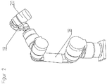
- FIG. 2 shows the robot 18 in an overall view
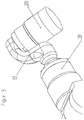
- FIG. 3 shows a section of the robot 18 with the area between the first and second robot arm 19 and 20, in which the transmission kit according to the invention is used.
- the local transmission component 4 with the driven component 13 integrally formed thereon has the largest axial extent of all components of the transmission kit.
- the gear kit can also be designed so that the wheel 6 has the largest axial extent of all components.
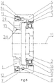
- the drive component 2 is designed as an elliptical wave generator. On this drive member 2 is over a plurality of balls 17 having ball bearing 16 as Flexspline formed elastic transmission member 4 is placed. Due to the elasticity in the region of its external toothing 3, this transmission component 4 is likewise elliptically deformed due to the elliptical shape of the drive component 2.
- the elastic transmission member 4 has an external toothing 3 and is elliptically deformed, this external toothing 3 is in the region of the large ellipse axis with an internal toothing 5 of a trained as a circular spline wheel 6 in engagement.
- This wheel 6 has an inner surface designed as a bearing surface 7, which corresponds to an outer surface of a bearing ring 1 designed as a bearing surface 9.
- a rolling bearing with a plurality of rolling elements 8 is arranged, wherein the bearing surfaces 7 and 9 of the wheel 6 and the bearing ring 1 are formed as raceways 12 for the rolling elements 8 of the rolling bearing ,
- the rolling elements 8 are formed in the present example as balls.
- the shape of the rolling elements 8, in particular their diameter, in relation to the substantially corresponding thereto round bearing surfaces 7, 9 adapt to provide the bearing with a bias.
- the rolling elements 8 are preferably located at four points of the track to functionally form a four-point bearing that can accommodate axial loads in both directions as well as radial loads and tilting moments.
- a receptacle 10 and in the bearing surface 9 of the bearing ring 1, a receptacle 11 is inserted in bearing surface 7 of the wheel 6.
- Both recordings 10 and 11 correspond in such a way that they are mutually aligned with a corresponding orientation, as for example in the FIG. 5 is shown, are suitable to receive a rolling element 8 positively to form a feed channel 24.
- the rolling bearing between wheel 6 and bearing ring 1 with rolling elements 8 via the supply channel 24 can be filled, so that the wheel 6 against the bearing ring 1 in particular play-free storable and bearing ring 1 and 6 wheel can be rotated against each other.
- the transmission component 4 embodied as a flexspline can now be driven by means of the drive component 2 designed as a wave generator, so that a relative movement takes place between the wheel 6 and the transmission component 4.
- the transmission member 4 Due to a fixation of the transmission member 4 by means of a driven component 13 on the Bearing ring 1 rotates in the present embodiment, the wheel 6 relative to the transmission member 4.
- the transmission member 4 is rotatably connected in the present embodiment by a tooth engagement and with positive engagement with the bearing ring 1.
- the output member 13 is integrally formed on the transmission member 4 in the present embodiment.
- the rotational movement of the transmission member 4 can be transmitted to other components within the device in which the transmission kit is to be used.
- the introduced into the wheel 6 and the bearing ring 1 raceways 12 are formed in the present embodiment so that the bearing can accommodate both radially acting forces and axial loads along the central longitudinal axis 15 in both directions.
- the output member 13 is at least partially disposed in the axial direction within the bearing ring 1 and is designed to save space due to its attached to the circumference radial tooth engagement in the bearing ring 1.
- the meshing takes place via a toothing 28 on the output member 13, which engages in a toothing 29 on the bearing ring 1.
- FIG. 5 is also very good to recognize that the components of the gear kit, namely the bearing ring 1, the drive member 2, the transmission member 4 and the wheel 6 are arranged coaxially about a central longitudinal axis 15 of the gear kit.
- FIG. 4 is again the transmission kit of FIG. 5 shown, but now in the state in which it is already installed in a robot 18. It can be clearly seen here that the axial space for the transmission kit is very low, so that the transmission kit according to the invention is particularly suitable for applications in which only a small amount of space is available for the realization of rotational movements.
- the transmission component 4 is held with its output component 13 by means of screw 21 and together with the bearing ring 1 rotatably on a first robot arm 19 of the robot 18 while the wheel 6 rotatably with a second robot arm 20 of the robot 18 is added.
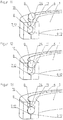
- FIGS. 6 and 7 two different positions of the receptacles 10 and 11 of the wheel 6 and the bearing ring 1 are shown.
- the receptacles 10 and 11 of the wheel 6 and the bearing ring 1 are positioned against each other so that they do not correspond to each other. Even if then a rolling element 8 assumes a position corresponding to the receptacle 10 in the bearing surface 7 of the wheel 6, as in FIG. 6 is shown, the rolling element 8 can not penetrate into this receptacle 10 of the wheel 6, since he is forced due to a non-existing there corresponding receptacle in the bearing surface 9 of the bearing ring 1 to remain in the raceway 12 for the rolling elements 8. In this position, the wheel and bearing ring can perform a relative rotational movement against each other, so that a relative rotational movement between the wheel 6 and the transmission member 4 takes place when the drive member 2 is driven or rotated.
- FIG. 7 the receptacle 10 and 11 of the wheel 6 and the bearing ring 1 positioned against each other such that a rolling element 8 is at least partially receivable.
- the receptacles 10 and 11 of the wheel 6 and the bearing ring 1 are designed such that the recording of the rolling element 8 is positively, so that the bearing ring 1 and the wheel 6 are free of play fixed against each other.
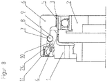
- FIG. 8 Another illustration of this positioning of the receptacles 10 and 11 of the wheel 6 and the bearing ring 1 is in FIG. 8 shown.
- FIG. 8 clearly seen that the rolling elements 8 can penetrate this positioning of the receptacles 10 and 11 in this, while the bearing ring 1 and the wheel 6 fixed against each other without play.
- closure elements 22, 23 may be formed, for example, as plugs 22, 23, which can be introduced into the supply channels 24 formed by the receptacles 10 and 11.
- the feed channels 24 can, as in FIG. 8 clarified be arranged so that their central longitudinal axis is parallel to the central longitudinal axis 15 of the transmission kit.
- These plugs can only be required if rotation angles greater than or equal to 360 ° are passed through on the output side of the gearbox kit. For torsions below 360 °, the plugs 22, 23 can therefore be dispensed with, since the receptacles 10, 11 do not coincide during operation and thus the rolling bodies 8 are trapped between the bearing surfaces 7, 9.
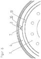
- FIG. 9 an embodiment of a wheel 6 of a transmission kit according to the invention is shown in a perspective partial view.
- the wheel 6 is provided on its inner surface with a trained as a raceway 12 bearing surface 7 for rolling elements 8, not shown here of a arranged between the wheel 6 and a bearing ring 1 rolling bearing.
- the wheel 6 has a receptacle 10 which can be closed by means of a closure element 22 designed as a plug 22.
- the plug 22 and the receptacle 10 have the same semicircular shape in cross section.
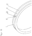
- FIG. 10 an embodiment of a bearing ring 1 of a transmission kit according to the invention shown in a partial perspective view.
- the bearing ring 1 is provided on its outer surface with a trained as a raceway 12 bearing surface 9 for rolling elements 8, not shown here of a arranged between the wheel 6 and the bearing ring 1 rolling bearing.
- the bearing ring 1 has a receptacle 11 which can be closed by means of a closure element 23 designed as a plug 23.
- the plug 23 and the receptacle 11 have the same semicircular shape in cross section and correspond to the shape of the in the FIG. 9 shown stopper 22 and the receptacle 10 of the wheel. 6
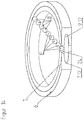
- FIG. 11 now shows the wheel 6 of FIG. 9 and the bearing ring 1 of FIG. 10 in a first mounting position during the filling of arranged between the wheel 6 and bearing ring 1 roller bearing with rolling elements 8.
- the semi-circular Receivers 10 and 11 of the wheel 6 and the bearing ring 1 are not closed with the plugs 22 and 23 and form a feed channel for the rolling elements 8 of the wheel 6 and bearing ring provided rolling bearing.
- Bearing ring 1 and 6 wheel are designed so that their trained as a raceway 12 bearing surfaces 7 and 9 allow a backlash-free rolling of the rolling elements 8.
- the rolling bearing between Rad 6 and bearing ring 1 is in the illustration of FIG. 11 already introduced a rolling element 8, while another in this representation in cross-section illustrated rolling elements 8 is approximated by the receptacles 10 and 11 formed feed channel 24.
- the wheel 6 is the FIG. 9 and the bearing ring 1 of FIG. 10 shown in a second representation of a mounting position during filling of arranged between the wheel 6 and bearing ring 1 rolling bearing, wherein the rolling element 8 shown in cross section is now already introduced into the feed channel 24 formed by the receptacles 10 and 11.
- the wheel 6 is the FIG. 9 and the bearing ring 1 of FIG. 10 shown in a third representation of a mounting position during the filling of the arranged between the wheel 6 and bearing ring 1 rolling bearing, wherein the rolling element 8 shown in cross section has now completely passed through the feed channel 24 formed by the receptacles 10 and 11 and between the raceways 12 of the bearing surfaces. 7 and 9 of the wheel 6 and the bearing ring 1 is positioned in the rolling bearing.
- FIG. 14 is a second embodiment of a wheel 6 and a bearing ring 1 of a transmission kit according to the invention shown in a detail sectional view.
- This embodiment corresponds essentially to the FIGS. 9 to 13 , wherein here, however, the feed channel 24 for the rolling elements 8 is inserted obliquely into the bearing ring 1 and the wheel 6.
- the rolling elements 8 can use their kinetic energy when filling in the raceway 12 to distribute in the raceway 12, which is bounded by the bearing surfaces 7 and 9 of the wheel 6 and the bearing ring 1.
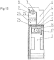
- FIG. 15 is a further embodiment of a transmission kit according to the invention shown in a flat design.
- this gear kit corresponds in terms of its operation to the embodiments described above.
- that is the component corresponding to the output member 13 is formed here as a dynamic spline 25.
- This dynamic spline 25 has an internal toothing 26 which, like the internal toothing 5 of the wheel 6, meshes with the external toothing 3 of the transmission component 4 designed as a flex spline.
- a bearing surface 9 is formed, in which the rolling elements 8 can run for supporting the dynamic spline 25 on the wheel 6.
- the rolling elements 8 run in a bearing surface 9 opposite the bearing surface 7 on the wheel.
- the bearing surface 7 is formed in the wheel 6.
- the transmission member 4 extends with its axial length both over the axial extent of the internal toothing 5 of the wheel 6, as well as over the axial extent of the internal toothing 26 of the dynamic spline 25, the external toothing 3 of the transmission member 4 each simultaneously in the internal toothing 5 of the wheel 6 and in the internal teeth 26 of the dynamic spline 25 engages to transmit the caused by the drive member 2 on the transmission member 4, reduced rotational motion on the output member 27, which in turn takes place by positive engagement of the external teeth 3 on the internal teeth 26 ,
- the wheel 6 is the component of the transmission kit, which has the largest axial extent.
Landscapes
- Engineering & Computer Science (AREA)
- General Engineering & Computer Science (AREA)
- Mechanical Engineering (AREA)
- Rolling Contact Bearings (AREA)
- Retarders (AREA)
- Support Of The Bearing (AREA)
- Mounting Of Bearings Or Others (AREA)
Applications Claiming Priority (2)
| Application Number | Priority Date | Filing Date | Title |
|---|---|---|---|
| DE102015104308.4A DE102015104308A1 (de) | 2015-03-23 | 2015-03-23 | Getriebeeinbausatz mit einem Abtriebslager und einem darin lagerbaren Spannungswellengetriebe |
| PCT/EP2016/055946 WO2016150844A1 (de) | 2015-03-23 | 2016-03-18 | Getriebeeinbausatz mit einem abtriebslager und einem daran lagerbaren spannungswellengetriebe |
Publications (2)
| Publication Number | Publication Date |
|---|---|
| EP3240960A1 EP3240960A1 (de) | 2017-11-08 |
| EP3240960B1 true EP3240960B1 (de) | 2018-06-20 |
Family
ID=55542673
Family Applications (1)
| Application Number | Title | Priority Date | Filing Date |
|---|---|---|---|
| EP16710455.3A Active EP3240960B1 (de) | 2015-03-23 | 2016-03-18 | Getriebeeinbausatz mit einem abtriebslager und einem daran lagerbaren spannungswellengetriebe |
Country Status (7)
| Country | Link |
|---|---|
| US (1) | US10876614B2 (enExample) |
| EP (1) | EP3240960B1 (enExample) |
| JP (1) | JP6718499B2 (enExample) |
| KR (1) | KR102007591B1 (enExample) |
| CN (1) | CN107407392B (enExample) |
| DE (1) | DE102015104308A1 (enExample) |
| WO (1) | WO2016150844A1 (enExample) |
Families Citing this family (14)
| Publication number | Priority date | Publication date | Assignee | Title |
|---|---|---|---|---|
| US10337561B2 (en) * | 2016-12-15 | 2019-07-02 | Boston Dynamics, Inc. | Transmission with integrated overload protection for a legged robot |
| CN110462258B (zh) * | 2017-04-10 | 2022-08-23 | 谐波传动系统有限公司 | 礼帽型波动齿轮装置 |
| US10253864B2 (en) * | 2017-07-03 | 2019-04-09 | Optimal Actuation Inc. | Bearing wave generator assembly |
| JP6739888B2 (ja) * | 2017-08-21 | 2020-08-12 | 株式会社ハーモニック・ドライブ・システムズ | 潤滑剤混合防止部を備えた波動歯車装置 |
| KR102782010B1 (ko) * | 2018-03-08 | 2025-03-18 | 나부테스코 가부시키가이샤 | 전달 장치 |
| CN109027022B (zh) * | 2018-09-30 | 2023-09-01 | 安徽工程大学 | 一种双机器人协同装配轴承的操作装置 |
| AT521617B1 (de) * | 2019-07-26 | 2020-03-15 | Univ Graz Tech | Koaxialgetriebe |
| JP2021055767A (ja) * | 2019-09-30 | 2021-04-08 | Ntn株式会社 | 玉軸受 |
| DE102020109646B4 (de) | 2020-04-07 | 2024-09-12 | Harmonic Drive Se | Drehlager und Getriebebox |
| JP6793867B1 (ja) * | 2020-06-29 | 2020-12-02 | 株式会社ハーモニック・ドライブ・システムズ | 波動歯車装置ユニット |
| DE102020208063B4 (de) | 2020-06-29 | 2022-02-10 | Kuka Deutschland Gmbh | Antriebsvorrichtung mit einer ein lichtstabilisiertes dynamisches Material aufweisenden Antriebskomponente und Roboter |
| JP2022077275A (ja) * | 2020-11-11 | 2022-05-23 | セイコーエプソン株式会社 | 駆動装置、及び駆動装置の組立て方法 |
| DE102023100528B3 (de) | 2023-01-11 | 2023-12-21 | Harmonic Drive Se | Getriebebox |
| DE102023100473B3 (de) * | 2023-01-11 | 2024-02-29 | Harmonic Drive Se | Lagereinheit mit integriertem Sensor |
Family Cites Families (27)
| Publication number | Priority date | Publication date | Assignee | Title |
|---|---|---|---|---|
| US1035463A (en) * | 1910-10-08 | 1912-08-13 | Edwin Oldfield | Ball-bearing. |
| US2143091A (en) * | 1936-02-11 | 1939-01-10 | Fafnir Bearing Co | Bearing |
| FR2045063A5 (enExample) * | 1969-05-30 | 1971-02-26 | Bayard Gaston | |
| DE2407477A1 (de) * | 1974-02-16 | 1975-08-28 | Skf Kugellagerfabriken Gmbh | Waelzlager und verfahren zu seiner herstellung |
| US4196947A (en) * | 1978-02-22 | 1980-04-08 | Clark Equipment Company | Adjustable four point contact bearing |
| US4524639A (en) * | 1983-06-23 | 1985-06-25 | Usm Corporation | Extended flexspline arrangement |
| JPS60143244A (ja) * | 1983-12-29 | 1985-07-29 | Mitsubishi Electric Corp | ハ−モニツクギヤ装置 |
| FR2599108B1 (fr) * | 1986-05-22 | 1990-08-17 | Alcatel Espace | Mecanisme d'entrainement a grand debattement pour utilisation dans le vide comportant un reducteur qui a subi des traitements de lubrification seche |
| JP3739016B2 (ja) * | 1995-12-08 | 2006-01-25 | 株式会社ハーモニック・ドライブ・システムズ | 撓み噛み合い式歯車装置のトルク検出装置 |
| KR200152266Y1 (ko) * | 1997-04-08 | 1999-07-15 | 윤석태 | 원통형 롤러 베어링 |
| JP2000120811A (ja) * | 1998-08-12 | 2000-04-28 | Teijin Seiki Co Ltd | 撓み噛み合い式減速機 |
| US6050155A (en) * | 1999-02-03 | 2000-04-18 | Harmonic Drive Technologies | Harmonic drive flexspline with integral flange support |
| JP2002031150A (ja) * | 2000-07-13 | 2002-01-31 | Harmonic Drive Syst Ind Co Ltd | 歯車装置ユニット |
| TWI252895B (en) | 2001-12-11 | 2006-04-11 | Harmonic Drive Systems | Planetary gear device |
| JP4263993B2 (ja) * | 2003-12-19 | 2009-05-13 | 日本トムソン株式会社 | 蓋付きクロスローラ軸受の製造方法 |
| JP4531439B2 (ja) * | 2004-04-23 | 2010-08-25 | 株式会社ハーモニック・ドライブ・システムズ | カップ型波動歯車装置 |
| JP2007321879A (ja) | 2006-06-01 | 2007-12-13 | Harmonic Drive Syst Ind Co Ltd | 回転位置センサ付き減速機ユニット |
| JP4877804B2 (ja) * | 2007-03-08 | 2012-02-15 | 株式会社ハーモニック・ドライブ・システムズ | 波動歯車減速機の潤滑方法および回転テーブル装置 |
| JP2008240831A (ja) * | 2007-03-26 | 2008-10-09 | Thk Co Ltd | 転がり軸受及び転がり軸受の組立て方法 |
| CN201162803Y (zh) | 2008-03-07 | 2008-12-10 | 哈尔滨工业大学 | 一种短杯型谐波齿轮减速器 |
| JP5071356B2 (ja) * | 2008-12-01 | 2012-11-14 | 株式会社デンソーウェーブ | ロボット用波動歯車減速装置 |
| US20120085188A1 (en) | 2009-07-02 | 2012-04-12 | Harmonic Drive Systems Inc. | Noncircular bearing, wave generator, and wave gear device |
| CN103534514B (zh) | 2011-05-16 | 2016-02-17 | 谐波传动系统有限公司 | 组合型波动齿轮装置 |
| CN202851612U (zh) | 2012-09-20 | 2013-04-03 | 北京中技克美谐波传动有限责任公司 | 一种谐波传动减速器 |
| DE112013002132T5 (de) | 2013-05-08 | 2015-02-19 | Harmonic Drive Systems Inc. | Wellgenerator eines Verformungswellgetriebes |
| CN105308357B (zh) * | 2013-06-20 | 2017-09-26 | 谐波传动系统有限公司 | 轴承保持件、轴承机构及波动齿轮装置 |
| US10253864B2 (en) * | 2017-07-03 | 2019-04-09 | Optimal Actuation Inc. | Bearing wave generator assembly |
-
2015
- 2015-03-23 DE DE102015104308.4A patent/DE102015104308A1/de not_active Withdrawn
-
2016
- 2016-03-18 CN CN201680017796.9A patent/CN107407392B/zh active Active
- 2016-03-18 US US15/558,100 patent/US10876614B2/en active Active
- 2016-03-18 EP EP16710455.3A patent/EP3240960B1/de active Active
- 2016-03-18 KR KR1020177026751A patent/KR102007591B1/ko active Active
- 2016-03-18 JP JP2018500854A patent/JP6718499B2/ja active Active
- 2016-03-18 WO PCT/EP2016/055946 patent/WO2016150844A1/de not_active Ceased
Non-Patent Citations (1)
| Title |
|---|
| None * |
Also Published As
| Publication number | Publication date |
|---|---|
| KR20170130427A (ko) | 2017-11-28 |
| KR102007591B1 (ko) | 2019-08-05 |
| CN107407392B (zh) | 2019-10-11 |
| DE102015104308A1 (de) | 2016-09-29 |
| JP2018511765A (ja) | 2018-04-26 |
| JP6718499B2 (ja) | 2020-07-08 |
| EP3240960A1 (de) | 2017-11-08 |
| WO2016150844A1 (de) | 2016-09-29 |
| US20180051789A1 (en) | 2018-02-22 |
| CN107407392A (zh) | 2017-11-28 |
| US10876614B2 (en) | 2020-12-29 |
Similar Documents
| Publication | Publication Date | Title |
|---|---|---|
| EP3240960B1 (de) | Getriebeeinbausatz mit einem abtriebslager und einem daran lagerbaren spannungswellengetriebe | |
| DE60205460T2 (de) | Planetengetriebe und dessen verwendung | |
| DE102017208800B3 (de) | Zahnrad für ein Planetengetriebe | |
| DE102012015051A1 (de) | Planetengetriebe | |
| EP2464894B1 (de) | Kugelgewindetrieb mit markierungen für anschlag und montageverfahren für einen solchen kugelgewindetrieb | |
| DE102008053914A1 (de) | Wellengenerator für ein Spannungswellengetriebe sowie Spannungswellengetriebe | |
| DE2142965B2 (de) | Gelagerte Keilwellenverbindung | |
| EP3364074B1 (de) | Wälzlagergetriebe | |
| DE102004008538B4 (de) | Differential mit einer Bolzenbefestigungsbaugruppe | |
| DE3014860A1 (de) | Uebersetzungsgetriebe | |
| EP2255104A1 (de) | Getriebe | |
| DE102020109646B4 (de) | Drehlager und Getriebebox | |
| DE102017219548B4 (de) | Zahnradanordnung | |
| EP3169913B1 (de) | Wellgetriebe mit trockenlauf | |
| EP3143294A1 (de) | Vorrichtung zum sichern eines spannelements gegen ungewolltes lösen | |
| WO2010015406A1 (de) | Getriebe | |
| WO2015083040A2 (de) | Planeten-schraubenrad-getriebe | |
| DE202008015150U1 (de) | Koaxiales Getriebe | |
| DE102005036362B4 (de) | Gehäuseloses Differential | |
| DE3641769A1 (de) | Antriebsanordnung | |
| WO2006058743A1 (de) | Getriebe | |
| EP3421789B1 (de) | Wälzlager für windenergieanlagentriebstrang | |
| WO2007147705A1 (de) | Anordnung eines planetenbolzens in einem planetenträger | |
| DE112022002761T5 (de) | Planetenuntersetzungsgetriebe mit mindestens einem Planetenrad mit mindestens einem Außengewindeabschnitt | |
| DE102022124121A1 (de) | Wälzlager |
Legal Events
| Date | Code | Title | Description |
|---|---|---|---|
| STAA | Information on the status of an ep patent application or granted ep patent |
Free format text: STATUS: THE INTERNATIONAL PUBLICATION HAS BEEN MADE |
|
| GRAP | Despatch of communication of intention to grant a patent |
Free format text: ORIGINAL CODE: EPIDOSNIGR1 |
|
| STAA | Information on the status of an ep patent application or granted ep patent |
Free format text: STATUS: GRANT OF PATENT IS INTENDED |
|
| PUAI | Public reference made under article 153(3) epc to a published international application that has entered the european phase |
Free format text: ORIGINAL CODE: 0009012 |
|
| 17P | Request for examination filed |
Effective date: 20170207 |
|
| AK | Designated contracting states |
Kind code of ref document: A1 Designated state(s): AL AT BE BG CH CY CZ DE DK EE ES FI FR GB GR HR HU IE IS IT LI LT LU LV MC MK MT NL NO PL PT RO RS SE SI SK SM TR |
|
| AX | Request for extension of the european patent |
Extension state: BA ME |
|
| GRAS | Grant fee paid |
Free format text: ORIGINAL CODE: EPIDOSNIGR3 |
|
| GRAJ | Information related to disapproval of communication of intention to grant by the applicant or resumption of examination proceedings by the epo deleted |
Free format text: ORIGINAL CODE: EPIDOSDIGR1 |
|
| GRAL | Information related to payment of fee for publishing/printing deleted |
Free format text: ORIGINAL CODE: EPIDOSDIGR3 |
|
| STAA | Information on the status of an ep patent application or granted ep patent |
Free format text: STATUS: REQUEST FOR EXAMINATION WAS MADE |
|
| GRAP | Despatch of communication of intention to grant a patent |
Free format text: ORIGINAL CODE: EPIDOSNIGR1 |
|
| STAA | Information on the status of an ep patent application or granted ep patent |
Free format text: STATUS: GRANT OF PATENT IS INTENDED |
|
| INTC | Intention to grant announced (deleted) | ||
| RIC1 | Information provided on ipc code assigned before grant |
Ipc: F16H 49/00 20060101ALN20180119BHEP Ipc: F16C 43/06 20060101AFI20180119BHEP Ipc: F16C 33/58 20060101ALN20180119BHEP |
|
| INTG | Intention to grant announced |
Effective date: 20180207 |
|
| RIN1 | Information on inventor provided before grant (corrected) |
Inventor name: SCHAFFER, MICHAEL Inventor name: MENDEL, MATTHIAS, DR. |
|
| GRAA | (expected) grant |
Free format text: ORIGINAL CODE: 0009210 |
|
| STAA | Information on the status of an ep patent application or granted ep patent |
Free format text: STATUS: THE PATENT HAS BEEN GRANTED |
|
| AK | Designated contracting states |
Kind code of ref document: B1 Designated state(s): AL AT BE BG CH CY CZ DE DK EE ES FI FR GB GR HR HU IE IS IT LI LT LU LV MC MK MT NL NO PL PT RO RS SE SI SK SM TR |
|
| DAV | Request for validation of the european patent (deleted) | ||
| DAX | Request for extension of the european patent (deleted) | ||
| REG | Reference to a national code |
Ref country code: GB Ref legal event code: FG4D Free format text: NOT ENGLISH |
|
| REG | Reference to a national code |
Ref country code: IE Ref legal event code: FG4D Free format text: LANGUAGE OF EP DOCUMENT: GERMAN |
|
| REG | Reference to a national code |
Ref country code: AT Ref legal event code: REF Ref document number: 1010812 Country of ref document: AT Kind code of ref document: T Effective date: 20180715 |
|
| REG | Reference to a national code |
Ref country code: DE Ref legal event code: R096 Ref document number: 502016001305 Country of ref document: DE |
|
| REG | Reference to a national code |
Ref country code: NL Ref legal event code: MP Effective date: 20180620 |
|
| PG25 | Lapsed in a contracting state [announced via postgrant information from national office to epo] |
Ref country code: FI Free format text: LAPSE BECAUSE OF FAILURE TO SUBMIT A TRANSLATION OF THE DESCRIPTION OR TO PAY THE FEE WITHIN THE PRESCRIBED TIME-LIMIT Effective date: 20180620 Ref country code: BG Free format text: LAPSE BECAUSE OF FAILURE TO SUBMIT A TRANSLATION OF THE DESCRIPTION OR TO PAY THE FEE WITHIN THE PRESCRIBED TIME-LIMIT Effective date: 20180920 Ref country code: LT Free format text: LAPSE BECAUSE OF FAILURE TO SUBMIT A TRANSLATION OF THE DESCRIPTION OR TO PAY THE FEE WITHIN THE PRESCRIBED TIME-LIMIT Effective date: 20180620 Ref country code: SE Free format text: LAPSE BECAUSE OF FAILURE TO SUBMIT A TRANSLATION OF THE DESCRIPTION OR TO PAY THE FEE WITHIN THE PRESCRIBED TIME-LIMIT Effective date: 20180620 Ref country code: NO Free format text: LAPSE BECAUSE OF FAILURE TO SUBMIT A TRANSLATION OF THE DESCRIPTION OR TO PAY THE FEE WITHIN THE PRESCRIBED TIME-LIMIT Effective date: 20180920 |
|
| REG | Reference to a national code |
Ref country code: LT Ref legal event code: MG4D |
|
| PG25 | Lapsed in a contracting state [announced via postgrant information from national office to epo] |
Ref country code: LV Free format text: LAPSE BECAUSE OF FAILURE TO SUBMIT A TRANSLATION OF THE DESCRIPTION OR TO PAY THE FEE WITHIN THE PRESCRIBED TIME-LIMIT Effective date: 20180620 Ref country code: HR Free format text: LAPSE BECAUSE OF FAILURE TO SUBMIT A TRANSLATION OF THE DESCRIPTION OR TO PAY THE FEE WITHIN THE PRESCRIBED TIME-LIMIT Effective date: 20180620 Ref country code: RS Free format text: LAPSE BECAUSE OF FAILURE TO SUBMIT A TRANSLATION OF THE DESCRIPTION OR TO PAY THE FEE WITHIN THE PRESCRIBED TIME-LIMIT Effective date: 20180620 Ref country code: GR Free format text: LAPSE BECAUSE OF FAILURE TO SUBMIT A TRANSLATION OF THE DESCRIPTION OR TO PAY THE FEE WITHIN THE PRESCRIBED TIME-LIMIT Effective date: 20180921 |
|
| PG25 | Lapsed in a contracting state [announced via postgrant information from national office to epo] |
Ref country code: NL Free format text: LAPSE BECAUSE OF FAILURE TO SUBMIT A TRANSLATION OF THE DESCRIPTION OR TO PAY THE FEE WITHIN THE PRESCRIBED TIME-LIMIT Effective date: 20180620 |
|
| PG25 | Lapsed in a contracting state [announced via postgrant information from national office to epo] |
Ref country code: CZ Free format text: LAPSE BECAUSE OF FAILURE TO SUBMIT A TRANSLATION OF THE DESCRIPTION OR TO PAY THE FEE WITHIN THE PRESCRIBED TIME-LIMIT Effective date: 20180620 Ref country code: RO Free format text: LAPSE BECAUSE OF FAILURE TO SUBMIT A TRANSLATION OF THE DESCRIPTION OR TO PAY THE FEE WITHIN THE PRESCRIBED TIME-LIMIT Effective date: 20180620 Ref country code: SK Free format text: LAPSE BECAUSE OF FAILURE TO SUBMIT A TRANSLATION OF THE DESCRIPTION OR TO PAY THE FEE WITHIN THE PRESCRIBED TIME-LIMIT Effective date: 20180620 Ref country code: PL Free format text: LAPSE BECAUSE OF FAILURE TO SUBMIT A TRANSLATION OF THE DESCRIPTION OR TO PAY THE FEE WITHIN THE PRESCRIBED TIME-LIMIT Effective date: 20180620 Ref country code: EE Free format text: LAPSE BECAUSE OF FAILURE TO SUBMIT A TRANSLATION OF THE DESCRIPTION OR TO PAY THE FEE WITHIN THE PRESCRIBED TIME-LIMIT Effective date: 20180620 Ref country code: IS Free format text: LAPSE BECAUSE OF FAILURE TO SUBMIT A TRANSLATION OF THE DESCRIPTION OR TO PAY THE FEE WITHIN THE PRESCRIBED TIME-LIMIT Effective date: 20181020 |
|
| PG25 | Lapsed in a contracting state [announced via postgrant information from national office to epo] |
Ref country code: ES Free format text: LAPSE BECAUSE OF FAILURE TO SUBMIT A TRANSLATION OF THE DESCRIPTION OR TO PAY THE FEE WITHIN THE PRESCRIBED TIME-LIMIT Effective date: 20180620 Ref country code: SM Free format text: LAPSE BECAUSE OF FAILURE TO SUBMIT A TRANSLATION OF THE DESCRIPTION OR TO PAY THE FEE WITHIN THE PRESCRIBED TIME-LIMIT Effective date: 20180620 Ref country code: IT Free format text: LAPSE BECAUSE OF FAILURE TO SUBMIT A TRANSLATION OF THE DESCRIPTION OR TO PAY THE FEE WITHIN THE PRESCRIBED TIME-LIMIT Effective date: 20180620 |
|
| REG | Reference to a national code |
Ref country code: DE Ref legal event code: R097 Ref document number: 502016001305 Country of ref document: DE |
|
| PLBE | No opposition filed within time limit |
Free format text: ORIGINAL CODE: 0009261 |
|
| STAA | Information on the status of an ep patent application or granted ep patent |
Free format text: STATUS: NO OPPOSITION FILED WITHIN TIME LIMIT |
|
| 26N | No opposition filed |
Effective date: 20190321 |
|
| PG25 | Lapsed in a contracting state [announced via postgrant information from national office to epo] |
Ref country code: DK Free format text: LAPSE BECAUSE OF FAILURE TO SUBMIT A TRANSLATION OF THE DESCRIPTION OR TO PAY THE FEE WITHIN THE PRESCRIBED TIME-LIMIT Effective date: 20180620 |
|
| PG25 | Lapsed in a contracting state [announced via postgrant information from national office to epo] |
Ref country code: SI Free format text: LAPSE BECAUSE OF FAILURE TO SUBMIT A TRANSLATION OF THE DESCRIPTION OR TO PAY THE FEE WITHIN THE PRESCRIBED TIME-LIMIT Effective date: 20180620 |
|
| PG25 | Lapsed in a contracting state [announced via postgrant information from national office to epo] |
Ref country code: MC Free format text: LAPSE BECAUSE OF FAILURE TO SUBMIT A TRANSLATION OF THE DESCRIPTION OR TO PAY THE FEE WITHIN THE PRESCRIBED TIME-LIMIT Effective date: 20180620 |
|
| REG | Reference to a national code |
Ref country code: CH Ref legal event code: PL |
|
| PG25 | Lapsed in a contracting state [announced via postgrant information from national office to epo] |
Ref country code: LU Free format text: LAPSE BECAUSE OF NON-PAYMENT OF DUE FEES Effective date: 20190318 Ref country code: AL Free format text: LAPSE BECAUSE OF FAILURE TO SUBMIT A TRANSLATION OF THE DESCRIPTION OR TO PAY THE FEE WITHIN THE PRESCRIBED TIME-LIMIT Effective date: 20180620 |
|
| REG | Reference to a national code |
Ref country code: BE Ref legal event code: MM Effective date: 20190331 |
|
| PG25 | Lapsed in a contracting state [announced via postgrant information from national office to epo] |
Ref country code: IE Free format text: LAPSE BECAUSE OF NON-PAYMENT OF DUE FEES Effective date: 20190318 Ref country code: CH Free format text: LAPSE BECAUSE OF NON-PAYMENT OF DUE FEES Effective date: 20190331 Ref country code: LI Free format text: LAPSE BECAUSE OF NON-PAYMENT OF DUE FEES Effective date: 20190331 |
|
| PG25 | Lapsed in a contracting state [announced via postgrant information from national office to epo] |
Ref country code: BE Free format text: LAPSE BECAUSE OF NON-PAYMENT OF DUE FEES Effective date: 20190331 Ref country code: FR Free format text: LAPSE BECAUSE OF NON-PAYMENT OF DUE FEES Effective date: 20190331 |
|
| REG | Reference to a national code |
Ref country code: DE Ref legal event code: R082 Ref document number: 502016001305 Country of ref document: DE Representative=s name: DR. MUELLER PATENTANWAELTE, DE Ref country code: DE Ref legal event code: R081 Ref document number: 502016001305 Country of ref document: DE Owner name: HARMONIC DRIVE SE, DE Free format text: FORMER OWNER: HARMONIC DRIVE AG, 65555 LIMBURG, DE |
|
| PG25 | Lapsed in a contracting state [announced via postgrant information from national office to epo] |
Ref country code: TR Free format text: LAPSE BECAUSE OF FAILURE TO SUBMIT A TRANSLATION OF THE DESCRIPTION OR TO PAY THE FEE WITHIN THE PRESCRIBED TIME-LIMIT Effective date: 20180620 |
|
| PG25 | Lapsed in a contracting state [announced via postgrant information from national office to epo] |
Ref country code: PT Free format text: LAPSE BECAUSE OF FAILURE TO SUBMIT A TRANSLATION OF THE DESCRIPTION OR TO PAY THE FEE WITHIN THE PRESCRIBED TIME-LIMIT Effective date: 20181022 Ref country code: MT Free format text: LAPSE BECAUSE OF FAILURE TO SUBMIT A TRANSLATION OF THE DESCRIPTION OR TO PAY THE FEE WITHIN THE PRESCRIBED TIME-LIMIT Effective date: 20180620 |
|
| GBPC | Gb: european patent ceased through non-payment of renewal fee |
Effective date: 20200318 |
|
| PG25 | Lapsed in a contracting state [announced via postgrant information from national office to epo] |
Ref country code: GB Free format text: LAPSE BECAUSE OF NON-PAYMENT OF DUE FEES Effective date: 20200318 |
|
| PG25 | Lapsed in a contracting state [announced via postgrant information from national office to epo] |
Ref country code: CY Free format text: LAPSE BECAUSE OF FAILURE TO SUBMIT A TRANSLATION OF THE DESCRIPTION OR TO PAY THE FEE WITHIN THE PRESCRIBED TIME-LIMIT Effective date: 20180620 |
|
| PG25 | Lapsed in a contracting state [announced via postgrant information from national office to epo] |
Ref country code: HU Free format text: LAPSE BECAUSE OF FAILURE TO SUBMIT A TRANSLATION OF THE DESCRIPTION OR TO PAY THE FEE WITHIN THE PRESCRIBED TIME-LIMIT; INVALID AB INITIO Effective date: 20160318 |
|
| REG | Reference to a national code |
Ref country code: AT Ref legal event code: MM01 Ref document number: 1010812 Country of ref document: AT Kind code of ref document: T Effective date: 20210318 |
|
| PG25 | Lapsed in a contracting state [announced via postgrant information from national office to epo] |
Ref country code: MK Free format text: LAPSE BECAUSE OF FAILURE TO SUBMIT A TRANSLATION OF THE DESCRIPTION OR TO PAY THE FEE WITHIN THE PRESCRIBED TIME-LIMIT Effective date: 20180620 |
|
| PG25 | Lapsed in a contracting state [announced via postgrant information from national office to epo] |
Ref country code: AT Free format text: LAPSE BECAUSE OF NON-PAYMENT OF DUE FEES Effective date: 20210318 |
|
| P01 | Opt-out of the competence of the unified patent court (upc) registered |
Effective date: 20230530 |
|
| PGFP | Annual fee paid to national office [announced via postgrant information from national office to epo] |
Ref country code: DE Payment date: 20250331 Year of fee payment: 10 |