EP3240946B1 - Rocker arm with abutment against axial movement through a stop by the rocker arm shaft and by the cylinder head - Google Patents
Rocker arm with abutment against axial movement through a stop by the rocker arm shaft and by the cylinder head Download PDFInfo
- Publication number
- EP3240946B1 EP3240946B1 EP15817986.1A EP15817986A EP3240946B1 EP 3240946 B1 EP3240946 B1 EP 3240946B1 EP 15817986 A EP15817986 A EP 15817986A EP 3240946 B1 EP3240946 B1 EP 3240946B1
- Authority
- EP
- European Patent Office
- Prior art keywords
- cylinder head
- pivot point
- arrangement according
- axial
- finger follower
- Prior art date
- Legal status (The legal status is an assumption and is not a legal conclusion. Google has not performed a legal analysis and makes no representation as to the accuracy of the status listed.)
- Active
Links
- 230000000903 blocking effect Effects 0.000 claims description 13
- 230000003100 immobilizing effect Effects 0.000 claims description 4
- 238000002485 combustion reaction Methods 0.000 claims 2
- 230000003534 oscillatory effect Effects 0.000 claims 1
- OKTJSMMVPCPJKN-UHFFFAOYSA-N Carbon Chemical compound [C] OKTJSMMVPCPJKN-UHFFFAOYSA-N 0.000 description 1
- 229910000831 Steel Inorganic materials 0.000 description 1
- 229910052799 carbon Inorganic materials 0.000 description 1
- 239000003575 carbonaceous material Substances 0.000 description 1
- 239000011248 coating agent Substances 0.000 description 1
- 238000000576 coating method Methods 0.000 description 1
- 229910003460 diamond Inorganic materials 0.000 description 1
- 239000010432 diamond Substances 0.000 description 1
- 238000006073 displacement reaction Methods 0.000 description 1
- 238000005265 energy consumption Methods 0.000 description 1
- 230000010354 integration Effects 0.000 description 1
- 238000004519 manufacturing process Methods 0.000 description 1
- 239000010959 steel Substances 0.000 description 1
Images


Classifications
-
- F—MECHANICAL ENGINEERING; LIGHTING; HEATING; WEAPONS; BLASTING
- F01—MACHINES OR ENGINES IN GENERAL; ENGINE PLANTS IN GENERAL; STEAM ENGINES
- F01L—CYCLICALLY OPERATING VALVES FOR MACHINES OR ENGINES
- F01L1/00—Valve-gear or valve arrangements, e.g. lift-valve gear
- F01L1/12—Transmitting gear between valve drive and valve
- F01L1/18—Rocking arms or levers
- F01L1/185—Overhead end-pivot rocking arms
-
- F—MECHANICAL ENGINEERING; LIGHTING; HEATING; WEAPONS; BLASTING
- F01—MACHINES OR ENGINES IN GENERAL; ENGINE PLANTS IN GENERAL; STEAM ENGINES
- F01L—CYCLICALLY OPERATING VALVES FOR MACHINES OR ENGINES
- F01L1/00—Valve-gear or valve arrangements, e.g. lift-valve gear
- F01L1/12—Transmitting gear between valve drive and valve
- F01L1/18—Rocking arms or levers
- F01L2001/187—Clips, e.g. for retaining rocker arm on pivot
Definitions
- the invention relates to an arrangement for a motor vehicle, comprising a cylinder head of a heat engine, a camshaft in rotation relative to the cylinder head, at least one articulation axis fixed on the cylinder head and offset with respect to the axis. camshaft rotation.
- the invention also relates to a motor vehicle as such, comprising at least one such arrangement.
- the object of the present invention is to provide an arrangement for a motor vehicle which overcomes the drawbacks listed above.
- an object of the invention is to provide such an arrangement which is both simple in design and implementation, inexpensive, reliable, and easy to integrate in situations of reduced bulk at the cylinder head.
- This object can be achieved by means of an arrangement for a motor vehicle, comprising a cylinder head of a heat engine, a camshaft in rotation relative to the cylinder head, at least one hinge pin fixed on the cylinder head and offset from the axis of rotation of the camshaft, and at least one distribution latch for controlling the intake and exhaust valves of the heat engine, mounted on the hinge pin and actuated according to an oscillating tilting movement around the articulation axis by a rotary cam of the camshaft, in which the axial stops of the distribution latch along the articulation axis are constituted by a blocking wall axial delimited by the cylinder head on the one hand and by the articulation axis on the other hand.
- the articulation axis can form a shoulder delimiting an axial blocking face, said axial blocking face and said blocking wall forming axial stops in directions opposite for the distribution latch.
- Each articulation axis can ensure the mounting of two angularly free distribution lugs relative to each other around the articulation axis.
- Each articulation axis can comprise two pivot shafts aligned with each other and each ensuring the mounting with a sliding pivot connection of a corresponding distribution latch.
- An axial play may be present between the distribution latch and the articulation axis of the oscillating arm on the one hand, and the axial locking wall on the other hand, between 0.05 mm and 0.2 mm.
- the articulation axis is preferably constituted by a part, in particular of the monobloc type or in one piece, independent of the cylinder head and fixed on a bearing face delimited by the cylinder head.
- the elements for fixing the articulation axis to the cylinder head comprise on the one hand at least one centering pin and on the other hand at least one fixing screw immobilizing the articulation axis of the swinging arm relative to the cylinder head in the position defined by the mechanical cooperation between each centering pin and the cylinder head, each centering pin and each fixing screw passing through through lumens formed through the axis of articulation of the swing arm.
- the articulation axis can be parallel to the camshaft.
- each distribution latch may include a zone in mechanical contact with the cam and mechanically urging a valve stem intended to be actuated in its translational movement by the movement oscillating of the distribution latch.
- the arrangement includes an adjustment pad interposed between the valve and the dispensing latch.
- a motor vehicle can include at least one such arrangement.
- the invention which will now be described, with reference to figures 2 to 6 , generally relates to an arrangement for a motor vehicle, comprising a cylinder head 10 of a heat engine, a camshaft 11 rotating relative to the cylinder head 10, at least one hinge pin 15 fixed on the cylinder head 10 and offset relative to the axis of rotation of the camshaft 11.
- the cylinder head 10 can optionally be equipped with a cylinder head cover 12, attached to an upper face of the one-piece remainder of the cylinder head 10.
- the fixing of the shaft cam 11 on the cylinder head 10 can in particular be done in the lower part by this cylinder head block and in the upper part by the cylinder head cover 12, substantially in the manner of two shells immobilizing bearings or bearings.
- the invention also relates to a motor vehicle as such, comprising at least one such arrangement.
- the arrangement also comprises at least one distribution latch 14 intended for controlling the intake and exhaust valves 13 of the heat engine, mounted on the hinge pin 15 and actuated in an oscillating movement tilting around the hinge axis 15 by a rotary cam 111 of the camshaft 11.
- the axial stops of the distribution latch 14 along the hinge axis 15 are constituted by an axial locking wall 101 delimited by the cylinder head 10 on the one hand, and by the articulation axis 15 on the other hand, in particular at the level of a suitable element of the articulation axis 15.
- the term “distribution latch” can be replaced by the term “swing arm”, as soon as such a swing arm is configured so that it can fulfill the function mentioned above.
- - screw of the valve 13 which is associated with it.
- the hinge pin 15 forms in particular a shoulder delimiting an axial locking face 157.
- the axial locking face 157 and the locking wall 101 form axial stops in opposite directions for the distribution latch 14 disposed and thus held axially therebetween.
- each articulation axis 15 preferably ensures the mounting of two distribution latches 14 angularly free relative to each other around the articulation axis 15.
- each articulation axis 15 can in particular comprise two pivot shafts 151 aligned with each other in the axial direction and each ensuring the mounting with sliding pivot connection of a corresponding distribution latch 14.
- Each pivot shaft 151 defines at its distal end an axial face 155, intended to come opposite a corresponding axial locking wall 101.
- a mounting clearance can be interposed between this axial face 155 and the axial locking wall 101, typically between 0.2 mm and 1 mm.
- the hinge pin 15 is disposed between two axial locking walls 101 delimited by the cylinder head 10 and spaced apart by a distance greater than the distance separating the two axial faces 155 that the hinge pin 15 includes between them. The difference between these two distances defines the mounting clearances mentioned in the previous paragraph.
- an axial clearance is present between the distribution latch 14 and the axial locking face 157 of the hinge pin 15 on the one hand, and the axial locking wall 101 on the other hand, typically between 0, 05 mm and 0.2 mm.
- Adjustment between hinge pin 15 and latch distribution 14 is preferably of the sliding axial type, such as a standard adjustment of the H7g6 type.
- This arrangement has the advantage, among other things, of making it possible to maintain the distribution latch 14 in the cylinder head 10, in an articulated manner with respect to the valves 13 and to the camshaft 11, with lateral clearance on its two lateral faces, c that is to say its faces oriented in the axial direction around which it exerts its oscillating reciprocating tilting movement.
- the lateral clearance between the latch 14 and its axial stops as defined here is necessary for mounting and to avoid mechanical friction and energy consumption. Such a clearance does not really affect the distribution law even if the presence of this clearance makes it possible to distribute the wear appreciably on the stem of the valve 13, since the slight displacement of the latch 14 within the limit of its clearance allows the point of contact not to remain always identical.
- each hinge pin 15 can ensure the mounting of a distribution latch 14 which is angularly mounted around the hinge axis 15.
- each hinge axis 15 may in particular comprise a single pivot shaft 151 ensuring the mounting with sliding pivot connection of the distribution latch 14.
- the articulation axis 15 consists of a part, in particular of the monobloc type or in one piece, independent of the cylinder head 10 and fixed on a bearing face 102 delimited by the cylinder head 10.
- the hinge pin 15 delimits, in particular in its lower part, a bearing face 152 coming into direct contact against the bearing face 102 of the cylinder head 10. This contact provides a support plane support for the hinge pin 15 relative to the cylinder head 10.
- the arrangement comprises elements for fixing the hinge pin 15 to the cylinder head 10, which may comprise on the one hand at least one centering pin 16 (and on the other hand at least one fixing screw 17 (immobilizing the hinge pin 15 relative to the cylinder head 10 in the position defined by the mechanical cooperation between each centering pin 16 and the cylinder head 10, each centering pin 16 and each fixing screw 17 passing through through lights 153, 154, 156 formed through the hinge pin 15.
- elements for fixing the hinge pin 15 to the cylinder head 10 may comprise on the one hand at least one centering pin 16 (and on the other hand at least one fixing screw 17 (immobilizing the hinge pin 15 relative to the cylinder head 10 in the position defined by the mechanical cooperation between each centering pin 16 and the cylinder head 10, each centering pin 16 and each fixing screw 17 passing through through lights 153, 154, 156 formed through the hinge pin 15.
- the elements for fixing the hinge pin 15 on the cylinder head 10 comprise two centering pins 16, as is made visible on the figure 4 , making it possible to obtain precision in the positioning of the hinge pin 15 on the cylinder head 10.
- the light 153 intended to be crossed by a centering pin 16 and the light 156 intended to be crossed by the fixing screw 17 may be of circular section.
- the light 154 intended to be traversed by the other centering pin 16 may have an oblong-shaped section, the length of which is oriented in the direction of pivoting of the latches 14.
- the articulation axis 15 is parallel to the camshaft 11.
- the adjustment of the parallelism is possible via the fixing elements or any other dedicated member.
- each distribution latch 14 comprises a zone in mechanical contact with the cam 111 and mechanically urging a stem of a valve 13 intended to be actuated in its translational movement by the oscillating movement of the dispensing latch 14.
- the arrangement may also include an adjustment pad 18 interposed between the valve 13 and the dispensing latch 14.
- the hinge pin 15, the centering pins 16 and the distribution lugs 14 will preferably be made of steel.
- the articulation axis 15 can be heat treated to reduce its wear phenomenon at the level of the shafts 151 and possibly coated by a coating or a deposit, in particular a carbonaceous material obtained in the form of a thin layer, for example of the “DLC” type. "(For" Diamond Like Carbon "in Anglo-Saxon terminology).
- the hinge pin 15 will preferably be configured so that it jointly holds at least one distribution latch, here the two distribution lugs 14, before being fixed to the cylinder head 10 by screwing via the fixing screw 17
- the articulation axis 15 will be positioned as parallel as possible to the camshaft 11, via at least one centering pin 16 provided for this purpose.
- the latches 14 After installing the valves 13 in the cylinder head 10, the latches 14 will be mounted on the articulation axis 15 by the shafts 151. Then, the assembly will be placed on the face 102 of the cylinder head 10, where the two pins of centering 16 and the fixing screw 17 will lock the hinge pin 15 relative to the cylinder head 10.
- the distribution latches 14 will articulate around the respective shafts 151 and each will be locked axially in translation, on its shaft 151, by the wall 101 of the cylinder head 10 on the one hand and by a suitable element of the hinge axis 15 itself, avoiding any recourse to any other part external to this arrangement as defined here.
- the above solution advantageously makes it possible to maintain two distribution lugs 14 with a single component part of the hinge pin 15 and a single screw 17. This results in a very advantageous saving of parts, allowing a saving of space, weight, manufacturing and assembly costs.
Landscapes
- Engineering & Computer Science (AREA)
- Mechanical Engineering (AREA)
- General Engineering & Computer Science (AREA)
- Valve-Gear Or Valve Arrangements (AREA)
- Valve Device For Special Equipments (AREA)
Description
L'invention concerne un agencement pour véhicule automobile, comprenant une culasse d'un moteur thermique, un arbre à came en rotation par rapport à la culasse, au moins un axe d'articulation fixé sur la culasse et décalé par rapport à l'axe de rotation de l'arbre à came.The invention relates to an arrangement for a motor vehicle, comprising a cylinder head of a heat engine, a camshaft in rotation relative to the cylinder head, at least one articulation axis fixed on the cylinder head and offset with respect to the axis. camshaft rotation.
L'invention concerne aussi un véhicule automobile en tant que tel, comprenant au moins un tel agencement.The invention also relates to a motor vehicle as such, comprising at least one such arrangement.
En référence à la
Un tel agencement donne satisfaction dans son fonctionnement mais est relativement complexe tant dans sa conception que son montage, est onéreux et présente des difficultés d'intégration dans un encombrement réduit, ce qui est la tendance actuelle au niveau du développement des moteurs thermiques et des architectures de compartiments moteurs.Such an arrangement is satisfactory in its operation but is relatively complex both in its design and its assembly, is expensive and presents difficulties of integration in a space requirement. reduced, which is the current trend in the development of heat engines and engine compartment architectures.
Des agencements comparables sont connus des documents
Le but de la présente invention est de proposer un agencement pour véhicule automobile qui remédie aux inconvénients listés ci-dessus.The object of the present invention is to provide an arrangement for a motor vehicle which overcomes the drawbacks listed above.
Notamment, un objet de l'invention est de fournir un tel agencement qui soit à la fois simple de conception et de mise en œuvre, peu onéreux, fiable, et facile à intégrer dans des situations d'encombrement réduit au niveau de la culasse.In particular, an object of the invention is to provide such an arrangement which is both simple in design and implementation, inexpensive, reliable, and easy to integrate in situations of reduced bulk at the cylinder head.
Ce but peut être atteint par l'intermédiaire d'un agencement pour véhicule automobile, comprenant une culasse d'un moteur thermique, un arbre à came en rotation par rapport à la culasse, au moins un axe d'articulation fixé sur la culasse et décalé par rapport à l'axe de rotation de l'arbre à came, et au moins un linguet de distribution destiné à la commande des soupapes d'admission et d'échappement du moteur thermique, monté sur l'axe d'articulation et actionné selon un mouvement oscillant de basculement autour de l'axe d'articulation par une came rotative de l'arbre à came, dans lequel les arrêts axiaux du linguet de distribution le long de l'axe d'articulation sont constitués par une paroi de blocage axial délimitée par la culasse d'une part et par l'axe d'articulation d'autre part.This object can be achieved by means of an arrangement for a motor vehicle, comprising a cylinder head of a heat engine, a camshaft in rotation relative to the cylinder head, at least one hinge pin fixed on the cylinder head and offset from the axis of rotation of the camshaft, and at least one distribution latch for controlling the intake and exhaust valves of the heat engine, mounted on the hinge pin and actuated according to an oscillating tilting movement around the articulation axis by a rotary cam of the camshaft, in which the axial stops of the distribution latch along the articulation axis are constituted by a blocking wall axial delimited by the cylinder head on the one hand and by the articulation axis on the other hand.
Du côté opposé à ladite paroi de blocage axial par rapport au linguet de distribution, l'axe d'articulation peut former un épaulement délimitant une face de blocage axial, ladite face de blocage axial et ladite paroi de blocage formant des arrêts axiaux dans des sens opposés pour le linguet de distribution.On the side opposite to said axial blocking wall with respect to the distribution latch, the articulation axis can form a shoulder delimiting an axial blocking face, said axial blocking face and said blocking wall forming axial stops in directions opposite for the distribution latch.
Chaque axe d'articulation peut assurer le montage de deux linguets de distribution angulairement libres l'un par rapport à l'autre autour de l'axe d'articulation.Each articulation axis can ensure the mounting of two angularly free distribution lugs relative to each other around the articulation axis.
Chaque axe d'articulation peut comprendre deux arbres de pivotement alignés entre eux et assurant chacun le montage à liaison pivot glissant d'un linguet de distribution correspondant.Each articulation axis can comprise two pivot shafts aligned with each other and each ensuring the mounting with a sliding pivot connection of a corresponding distribution latch.
Un jeu axial peut être présent entre le linguet de distribution et l'axe d'articulation de bras oscillant d'une part, et la paroi de blocage axial d'autre part, compris entre 0,05 mm et 0,2 mm.An axial play may be present between the distribution latch and the articulation axis of the oscillating arm on the one hand, and the axial locking wall on the other hand, between 0.05 mm and 0.2 mm.
L'axe d'articulation est de préférence constitué par une pièce, notamment de type monobloc ou d'un seul tenant, indépendante de la culasse et fixée sur une face d'appui délimitée par la culasse.The articulation axis is preferably constituted by a part, in particular of the monobloc type or in one piece, independent of the cylinder head and fixed on a bearing face delimited by the cylinder head.
Les éléments de fixation de l'axe d'articulation sur la culasse comprennent d'une part au moins un pion de centrage et d'autre part au moins une vis de fixation immobilisant l'axe d'articulation de bras oscillant par rapport à la culasse dans la position définie par la coopération mécanique entre chaque pion de centrage et la culasse, chaque pion de centrage et chaque vis de fixation traversant des lumières traversantes ménagées à travers l'axe d'articulation de bras oscillant.The elements for fixing the articulation axis to the cylinder head comprise on the one hand at least one centering pin and on the other hand at least one fixing screw immobilizing the articulation axis of the swinging arm relative to the cylinder head in the position defined by the mechanical cooperation between each centering pin and the cylinder head, each centering pin and each fixing screw passing through through lumens formed through the axis of articulation of the swing arm.
L'axe d'articulation peut être parallèle à l'arbre à came.The articulation axis can be parallel to the camshaft.
Du côté opposé à sa zone de liaison à l'axe de pivotement, chaque linguet de distribution peut comprendre une zone en contact mécanique avec la came et sollicitant mécaniquement une queue d'une soupape destinée à être actionnée dans son mouvement de translation par le mouvement oscillant du linguet de distribution.On the side opposite its zone of connection to the pivot axis, each distribution latch may include a zone in mechanical contact with the cam and mechanically urging a valve stem intended to be actuated in its translational movement by the movement oscillating of the distribution latch.
Sur la queue de la soupape, l'agencement comprend une pastille de réglage interposée entre la soupape et le linguet de distribution.On the valve stem, the arrangement includes an adjustment pad interposed between the valve and the dispensing latch.
Un véhicule automobile peut comprendre au moins un tel agencement.A motor vehicle can include at least one such arrangement.
D'autres avantages et caractéristiques ressortiront plus clairement de la description qui va suivre de modes particuliers de réalisation de l'invention donnés à titre d'exemples non limitatifs et représentés sur les dessins annexés, dans lesquels :
- la
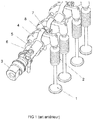
figure 1 , déjà décrite, est une vue en perspective d'un exemple d'agencement connu de l'art antérieur, - la
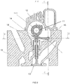
figure 2 est une vue en coupe selon un plan de coupe A-A d'un exemple d'agencement selon l'invention, - la
figure 3 est une vue en coupe selon un plan de coupe B-B visible sur lafigure 2 , de l'exemple d'agencement illustré sur lafigure 2 , - la
figure 4 est une vue en coupe selon un plan de coupe C-C visible sur lafigure 2 , de l'exemple d'agencement illustré sur lesfigures 2 et3 , - la
figure 5 est une vue en coupe selon un plan de coupe D-D visible sur lafigure 3 , de l'exemple d'agencement représenté sur lesfigures 2 à 4 , et - la
figure 6 est une vue en perspective d'un exemple d'axe d'articulation tel qu'utilisé dans l'agencement desfigures 2 à 5 .
- the
figure 1 , already described, is a perspective view of an example of an arrangement known from the prior art, - the
figure 2 is a sectional view along a sectional plane AA of an exemplary arrangement according to the invention, - the
figure 3 is a sectional view along a section plane BB visible on thefigure 2 , of the example of arrangement illustrated on thefigure 2 , - the
figure 4 is a sectional view along a sectional plane CC visible on thefigure 2 , of the example of arrangement illustrated on thefigures 2 and3 , - the
figure 5 is a sectional view along a DD cutting plane visible on thefigure 3 , of the example of arrangement represented on thefigures 2 to 4 , and - the
figure 6 is a perspective view of an example of a hinge axis as used in the arrangement offigures 2 to 5 .
L'invention qui va maintenant être décrite, en référence aux
L'invention concerne aussi un véhicule automobile en tant que tel, comprenant au moins un tel agencement.The invention also relates to a motor vehicle as such, comprising at least one such arrangement.
Selon une caractéristique importante, l'agencement comprend aussi au moins un linguet de distribution 14 destiné à la commande des soupapes 13 d'admission et d'échappement du moteur thermique, monté sur l'axe d'articulation 15 et actionné selon un mouvement oscillant de basculement autour de l'axe d'articulation 15 par une came rotative 111 de l'arbre à came 11. Les arrêts axiaux du linguet de distribution 14 le long de l'axe d'articulation 15 sont constitués par une paroi de blocage axial 101 délimitée par la culasse 10 d'une part, et par l'axe d'articulation 15 d'autre part, notamment au niveau d'un élément idoine de l'axe d'articulation 15.According to an important characteristic, the arrangement also comprises at least one
Dans tout ce document, le terme « linguet de distribution » peut indifféremment être remplacé par le terme « bras oscillant », dès lors qu'un tel bras oscillant est configuré de telle sorte qu'il puisse remplir la fonction pré-mentionnée vis-à-vis de la soupape 13 qui lui est associée.Throughout this document, the term “distribution latch” can be replaced by the term “swing arm”, as soon as such a swing arm is configured so that it can fulfill the function mentioned above. - screw of the
Du côté opposé à la paroi de blocage axial 101 par rapport au linguet de distribution 14, l'axe d'articulation 15 forme notamment un épaulement délimitant une face de blocage axial 157. La face de blocage axial 157 et la paroi de blocage 101 forment des arrêts axiaux dans des sens opposés pour le linguet de distribution 14 disposé et ainsi maintenu axialement entre elles.On the side opposite to the
Chaque axe d'articulation 15 assure de préférence le montage de deux linguets de distribution 14 angulairement libres l'un par rapport à l'autre autour de l'axe d'articulation 15. A cet effet, chaque axe d'articulation 15 peut notamment comprendre deux arbres de pivotement 151 alignés entre eux selon la direction axiale et assurant chacun le montage à liaison pivot glissant d'un linguet de distribution 14 correspondant.Each
Chaque arbre de pivotement 151 délimite à son extrémité distale une face axiale 155, destinée à venir en regard d'une paroi de blocage axial 101 correspondante. Un jeu de montage peut être interposé entre cette face axiale 155 et la paroi de blocage axial 101, typiquement compris entre 0.2 mm et 1 mm.Each
Ainsi, l'axe d'articulation 15 est disposé entre deux parois de blocage axial 101 délimitées par la culasse 10 et distantes entre elles d'une distance supérieure à la distance séparant les deux faces axiales 155 que comprend l'axe d'articulation 15 entre elles. La différence entre ces deux distances définit les jeux de montage évoqués au paragraphe précédent.Thus, the
Préférentiellement, un jeu axial est présent entre le linguet de distribution 14 et la face de blocage axial 157 de l'axe d'articulation 15 d'une part, et la paroi de blocage axial 101 d'autre part, typiquement compris entre 0,05 mm et 0,2 mm. L'ajustement entre l'axe d'articulation 15 et le linguet de distribution 14 est de préférence de type axial glissant, tel qu'un ajustement normé de type H7g6.Preferably, an axial clearance is present between the
Plus précisément, il est possible de prévoir un premier jeu d'un coté, entre le linguet de distribution 14 et la face 157 de l'axe d'articulation 15 et un deuxième jeu de l'autre côté, entre le linguet de distribution 14 et la paroi de blocage axial 101. Ces jeux sont illustrés sur les
Cette disposition présente l'intérêt entre autres de permettre de maintenir le linguet de distribution 14 dans la culasse 10, de manière articulée par rapport aux soupapes 13 et à l'arbre à came 11, avec un jeu latéral sur ses deux faces latérales, c'est-à-dire ses faces orientées suivant la direction axiale autour de laquelle il exerce son mouvement oscillant de basculement alternatif.This arrangement has the advantage, among other things, of making it possible to maintain the
Le jeu latéral entre le linguet 14 et ses arrêts axiaux tels que définis ici est nécessaire au montage et pour éviter les frottements mécaniques et la consommation d'énergie. Un tel jeu n'a pas réellement d'incidence sur la loi de distribution même si la présence de ce jeu permet de répartir sensiblement l'usure sur la queue de la soupape 13, puisque le léger déplacement du linguet 14 dans la limite de son jeu permet au point de contact de ne pas rester toujours identique.The lateral clearance between the
Selon une variante de réalisation non représentée, chaque axe d'articulation 15 peut assurer le montage d'un linguet de distribution 14 qui est monté angulairement libre autour de l'axe d'articulation 15. A cet effet, chaque axe d'articulation 15 peut notamment comprendre un unique arbre de pivotement 151 assurant le montage à liaison pivot glissant du linguet de distribution 14.According to an alternative embodiment not shown, each
Selon un mode de réalisation non limitatif quant à la liberté de conception de l'axe d'articulation 15, celui-ci est constitué par une pièce, notamment de type monobloc ou d'un seul tenant, indépendante de la culasse 10 et fixée sur une face d'appui 102 délimitée par la culasse 10. A cet effet, l'axe d'articulation 15 délimite, notamment dans sa partie inférieure, une face d'appui 152 venant en contact direct contre la face d'appui 102 de la culasse 10. Ce contact assure une liaison appui-plan pour l'axe d'articulation 15 par rapport à la culasse 10.According to a nonlimiting embodiment with regard to the freedom of design of the
En complément, l'agencement comprend des éléments de fixation de l'axe d'articulation 15 sur la culasse 10, qui peuvent comprendre d'une part au moins un pion de centrage 16 (et d'autre part au moins une vis de fixation 17 (immobilisant l'axe d'articulation 15 par rapport à la culasse 10 dans la position définie par la coopération mécanique entre chaque pion de centrage 16 et la culasse 10, chaque pion de centrage 16 et chaque vis de fixation 17 traversant des lumières traversantes 153, 154, 156 ménagées à travers l'axe d'articulation 15.In addition, the arrangement comprises elements for fixing the
Dans le mode de réalisation illustré sur la
La lumière 153 destinée à être traversée par un pion de centrage 16 et la lumière 156 destinée à être traversée par la vis de fixation 17 peuvent être de section circulaire. Par contre, la lumière 154 destinée à être traversée par l'autre pion de centrage 16 peut présenter une section de forme oblongue, dont la longueur est orientée selon la direction de pivotement des linguets 14.The light 153 intended to be crossed by a centering
Préférentiellement, l'axe d'articulation 15 est parallèle à l'arbre à came 11. Le réglage du parallélisme est possible via les éléments de fixation ou tout autre organe dédié.Preferably, the
Selon un mode de réalisation particulier, du côté opposé à sa zone de liaison à l'axe de pivotement 15, chaque linguet de distribution 14 comprend une zone en contact mécanique avec la came 111 et sollicitant mécaniquement une queue d'une soupape 13 destinée à être actionnée dans son mouvement de translation par le mouvement oscillant du linguet de distribution 14. Sur la queue de la soupape 13, l'agencement peut comprendre également une pastille de réglage 18 interposée entre la soupape 13 et le linguet de distribution 14.According to a particular embodiment, on the side opposite its zone of connection to the
Contrairement aux culbuteurs 4 de l'art antérieur pour lesquels les appuis respectivement contre l'arbre à came 3 et contre la soupape 1 sont disposés de part et d'autre de l'axe d'articulation 5 du culbuteur 4, la solution décrite ici permet, pour chaque linguet de distribution 14, que les appuis mécaniques respectivement contre l'arbre à came 11 et contre la soupape 13 se pratique dans une seule et même zone, notamment agencée à une extrémité du linguet 14 opposée à l'extrémité au niveau de laquelle il est articulé autour de l'axe d'articulation 15. Il en résulte une simplification et un gain de place très importants.Unlike the rocker arms 4 of the prior art for which the supports respectively against the
Dans un mode de réalisation non limitatif, l'axe d'articulation 15, les pions de centrage 16 et les linguets de distribution 14 seront préférentiellement réalisés en acier. L'axe d'articulation 15 pourra être traité thermiquement pour réduire son phénomène d'usure au niveau des arbres 151 et éventuellement revêtu par un revêtement ou un dépôt, notamment un matériau carboné obtenu sous forme de couche mince, par exemple de type « DLC » (pour « Diamond Like Carbon » en terminologie anglo-saxonne).In a nonlimiting embodiment, the
Le montage de l'agencement détaillé précédemment peut se pratiquer de la manière suivante.The assembly of the arrangement detailed previously can be practiced in the following manner.
L'axe d'articulation 15 sera préférentiellement configuré de telle sorte qu'il maintienne conjointement au moins un linguet de distribution, ici les deux linguets de distribution 14, avant d'être fixé sur la culasse 10 par vissage via la vis de fixation 17. L'axe d'articulation 15 sera positionné le plus parallèlement possible à l'arbre à came 11, via au moins un pion de centrage 16 prévu à cet effet.The
Après avoir installé les soupapes 13 dans la culasse 10, les linguets 14 seront montés sur l'axe d'articulation 15 par les arbres 151. Puis, l'ensemble sera placé sur la face 102 de la culasse 10, où les deux pions de centrage 16 et la vis de fixation 17 assureront le blocage de l'axe d'articulation 15 par rapport à la culasse 10.After installing the
Les linguets de distribution 14 s'articuleront autour des arbres 151 respectifs et chacun sera bloqué axialement en translation, sur son arbre 151, par la paroi 101 de la culasse 10 d'une part et par un élément idoine de l'axe d'articulation 15 lui-même, évitant tout recours à toute autre pièce externe à cet agencement tel que défini ici.The distribution latches 14 will articulate around the
La solution précédente permet avantageusement de maintenir deux linguets de distribution 14 avec une seule pièce constitutive de l'axe d'articulation 15 et une seule vis 17. Il en résulte une économie très avantageuse de pièces, permettant un gain de place, de poids, de coût de fabrication et de montage.The above solution advantageously makes it possible to maintain two distribution lugs 14 with a single component part of the
La solution qui vient d'être décrite présente l'avantage également d'être à la fois simple de conception et de mise en œuvre, peu onéreuse, fiable, et facile à intégrer dans des situations d'encombrement réduit au niveau de la culasse.The solution which has just been described also has the advantage of being both simple in design and in implementation, inexpensive, reliable, and easy to integrate in situations of reduced bulk at the cylinder head.
Claims (11)
- Arrangement for a motor vehicle, comprising a cylinder head (10) of an internal combustion engine, a camshaft (11) rotating relative to the cylinder head (10), at least one pivot point (15) fixed to the cylinder head (10), arranged between two blocking walls of the cylinder head and offset relative to the rotation axis of the camshaft (11), and at least one timing finger follower (14) which is intended to control the inlet and exhaust valves (13) of the internal combustion engine, mounted on the pivot point (15) and actuated in an oscillatory rocking motion about the pivot point (15) by a rotary cam (111) of the camshaft (11), wherein the axial stops for the timing finger follower (14) along the pivot point (15) are constituted by an axial blocking wall (101) delimited by the cylinder head (10) on one side and by the pivot point (15) on the other.
- Arrangement according to Claim 1, characterized in that, on the side opposite said axial blocking wall (101) relative to the timing finger follower (14), the pivot point (15) forms a shoulder delimiting an axial blocking face (157), said axial blocking face (157) and said blocking wall (101) forming axial stops in opposite directions for the timing finger follower (14).
- Arrangement according to either of Claims 1 and 2, characterized in that each pivot point (15) serves for mounting two timing finger followers (14) angularly separated from each other around the pivot point (15).
- Arrangement according to any one of Claims 1 to 3, characterized in that each pivot point (15) comprises two pivot shafts (151) aligned to each other and each serving for mounting a corresponding timing finger follower (14) by sliding pivot connection.
- Arrangement according to any one of Claims 1 to 4, characterized in that an axial clearance is present between the timing finger follower (14) and the pivot point (15) of the oscillating arm on one side and the axial blocking wall (101) on the other, of between 0.05 mm and 0.2 mm.
- Arrangement according to any one of Claims 1 to 5, characterized in that the pivot point (15) is formed from one piece, in particular of the monobloc or integral type, independent of the cylinder head (10) and fixed to a support face (102) delimited by the cylinder head (10).
- Arrangement according to Claim 6, characterized in that the elements for fixing the pivot point (15) on the cylinder head (10) comprise firstly at least one centring stud (16) and secondly at least one fixing screw (17), immobilizing the pivot point (15) of the oscillating arm relative to the cylinder head (10) in the position defined by the mechanical cooperation between each centring stud (16) and the cylinder head (10), each centring stud (16) and each fixing screw (17) passing through passage openings (153, 154, 156) arranged through the pivot point (15) of the oscillating arm.
- Arrangement according to any one of Claims 1 to 7, characterized in that the pivot point (15) is parallel to the camshaft (11).
- Arrangement according to any one of Claims 1 to 8, characterized in that, on the side opposite its zone for connection to the pivot point (15), each timing finger follower (14) comprises a zone in mechanical contact with the cam (111) and mechanically stressing a stem of a valve (13) which is intended to be actuated in its translation motion by the oscillating motion of the timing finger follower (14) .
- Arrangement according to Claim 9, characterized in that, on the stem of the valve (13), the arrangement comprises an adjustment lug (18) interposed between the valve (13) and the timing finger follower (14).
- Motor vehicle comprising at least one arrangement according to any one of the preceding claims.
Applications Claiming Priority (2)
| Application Number | Priority Date | Filing Date | Title |
|---|---|---|---|
| FR1463377A FR3031137B1 (en) | 2014-12-29 | 2014-12-29 | DISTRIBUTION LINGUETS AXIALLY ADJUSTED BY AXIS JOINT AND CYLINDER HEAD |
| PCT/FR2015/053408 WO2016108002A1 (en) | 2014-12-29 | 2015-12-10 | Timing finger followers stopped axially by the pivot and by the cylinder head |
Publications (2)
| Publication Number | Publication Date |
|---|---|
| EP3240946A1 EP3240946A1 (en) | 2017-11-08 |
| EP3240946B1 true EP3240946B1 (en) | 2020-02-05 |
Family
ID=52684509
Family Applications (2)
| Application Number | Title | Priority Date | Filing Date |
|---|---|---|---|
| EP15817986.1A Active EP3240946B1 (en) | 2014-12-29 | 2015-12-10 | Rocker arm with abutment against axial movement through a stop by the rocker arm shaft and by the cylinder head |
| EP16785229.2A Active EP3356655B1 (en) | 2014-12-29 | 2016-09-27 | Cylinder head |
Family Applications After (1)
| Application Number | Title | Priority Date | Filing Date |
|---|---|---|---|
| EP16785229.2A Active EP3356655B1 (en) | 2014-12-29 | 2016-09-27 | Cylinder head |
Country Status (7)
| Country | Link |
|---|---|
| EP (2) | EP3240946B1 (en) |
| JP (2) | JP2018500503A (en) |
| KR (2) | KR20170102318A (en) |
| CN (2) | CN107208501B (en) |
| FR (2) | FR3031137B1 (en) |
| RU (1) | RU2698558C2 (en) |
| WO (2) | WO2016108002A1 (en) |
Families Citing this family (1)
| Publication number | Priority date | Publication date | Assignee | Title |
|---|---|---|---|---|
| CN109307497B (en) * | 2018-10-30 | 2023-10-24 | 广西玉柴机器股份有限公司 | Automatic measuring device for rotation moment of engine crankshaft and roundness of rotating shaft |
Family Cites Families (35)
| Publication number | Priority date | Publication date | Assignee | Title |
|---|---|---|---|---|
| FR363870A (en) * | 1906-03-06 | 1906-08-09 | Rolland Et Em Pilain Soc | Valve control device in internal combustion engines |
| US2263649A (en) * | 1938-04-04 | 1941-11-25 | Emerson D Sawyer | Post type yieldable barrier |
| US2264649A (en) * | 1938-05-21 | 1941-12-02 | Automobili Isotta Fraschini Fa | Valve gear for engines |
| FR1588976A (en) * | 1967-10-03 | 1970-03-16 | ||
| DE1955085A1 (en) * | 1969-11-03 | 1971-05-13 | Daimler Benz Ag | Axial fixation of rocker arms in internal combustion engines |
| JPS6021445Y2 (en) * | 1980-02-14 | 1985-06-26 | 日産自動車株式会社 | Rocker arm mounting structure |
| SU1079863A1 (en) * | 1981-10-28 | 1984-03-15 | Pezhemskij Nikolaj B | Gas distributing mechanism |
| JPS6111407A (en) * | 1984-06-26 | 1986-01-18 | Honda Motor Co Ltd | Tappet device of internal-combustion engine |
| JPS6116202A (en) * | 1984-07-03 | 1986-01-24 | Honda Motor Co Ltd | Valve rocker arm device of internal-combustion engine |
| JPH059444Y2 (en) * | 1986-07-11 | 1993-03-09 | ||
| FR2643676B1 (en) * | 1989-02-28 | 1991-06-07 | Peugeot | ROCKER FOR ACTUATING A ROD VALVE OF AN INTERNAL COMBUSTION ENGINE |
| GB2245647A (en) * | 1990-06-27 | 1992-01-08 | Ford Motor Co | Variable i.c. engine valve timing |
| US5365895A (en) * | 1991-12-03 | 1994-11-22 | Motive Holdings Limited | Variable valve lift mechanism for internal combustion engine |
| JPH05256110A (en) * | 1992-03-13 | 1993-10-05 | Suzuki Motor Corp | Valve system of engine |
| DE4244326A1 (en) * | 1992-12-28 | 1994-06-30 | Kloeckner Humboldt Deutz Ag | IC engine valve operating rocker lever |
| FR2733539B1 (en) | 1995-04-28 | 1997-06-13 | Renault | VARIABLE DISTRIBUTION DEVICE FOR INTERNAL COMBUSTION ENGINE |
| DE19608410C1 (en) * | 1996-03-05 | 1997-06-12 | Audi Ag | Valve operating lever for internal combustion engine |
| JP3846250B2 (en) * | 2001-10-04 | 2006-11-15 | 日本精工株式会社 | Rocker arm |
| JP2003269116A (en) * | 2002-03-12 | 2003-09-25 | Toyota Motor Corp | Valve train for internal combustion engine |
| JP3643351B2 (en) * | 2002-04-24 | 2005-04-27 | 本田技研工業株式会社 | Rocker arm support device |
| US6722331B2 (en) * | 2002-06-28 | 2004-04-20 | Tecumseh Products Company | Valve clearance adjustment mechanism |
| JP4103489B2 (en) * | 2002-08-01 | 2008-06-18 | 株式会社ジェイテクト | Cam follower |
| FR2861130B1 (en) | 2003-10-15 | 2007-06-08 | Renault Sa | DEVICE FOR DISTRIBUTING HEAT ENGINE |
| DE102004049836A1 (en) * | 2004-10-13 | 2006-05-04 | Daimlerchrysler Ag | Internal combustion engine has valve control unit that has cam lever with contact area arranged over valve shaft end area of gas shutter valve, in which contact area of cam lever is formed with different radii points |
| US7318402B2 (en) * | 2005-11-21 | 2008-01-15 | Eaton Corporation | Dual lift rocker arm latch mechanism and actuation arrangement therefor |
| CN2903395Y (en) * | 2006-06-08 | 2007-05-23 | 庄德建 | Air valve swinging arm mechanism with improved structure |
| JP4920476B2 (en) * | 2007-03-30 | 2012-04-18 | 本田技研工業株式会社 | Engine valve gear |
| DE102007032638A1 (en) * | 2007-07-11 | 2009-01-15 | Bayerische Motoren Werke Aktiengesellschaft | Internal combustion engine with a crankshaft and at least one cylinder head and motor vehicle with such an internal combustion engine |
| JP5499557B2 (en) * | 2009-08-07 | 2014-05-21 | スズキ株式会社 | Valve gear |
| DE102011106395A1 (en) * | 2011-07-02 | 2013-01-03 | Man Truck & Bus Ag | Valve control for at least one valve of an internal combustion engine |
| CN103477036A (en) * | 2011-10-04 | 2013-12-25 | 日锻汽门株式会社 | Rocker arm for valve train |
| JP2013144941A (en) * | 2012-01-13 | 2013-07-25 | Suzuki Motor Corp | Valve gear of internal combustion engine |
| JP5757899B2 (en) * | 2012-03-06 | 2015-08-05 | 株式会社オティックス | Valve mechanism shim and valve mechanism |
| RU2500896C1 (en) * | 2012-04-11 | 2013-12-10 | Федеральное государственное бюджетное образовательное учреждение высшего профессионального образования "Елецкий государственный университет им. И.А. Бунина" | Gas distributing mechanism of internal combustion engine |
| DE102013211584A1 (en) * | 2013-06-20 | 2015-01-08 | Schaeffler Technologies Gmbh & Co. Kg | Operating lever in the form of a towing, swiveling or tilting lever |
-
2014
- 2014-12-29 FR FR1463377A patent/FR3031137B1/en not_active Expired - Fee Related
-
2015
- 2015-09-30 FR FR1559268A patent/FR3031138B1/en not_active Expired - Fee Related
- 2015-12-10 EP EP15817986.1A patent/EP3240946B1/en active Active
- 2015-12-10 RU RU2017127159A patent/RU2698558C2/en active
- 2015-12-10 JP JP2017534647A patent/JP2018500503A/en active Pending
- 2015-12-10 WO PCT/FR2015/053408 patent/WO2016108002A1/en active Application Filing
- 2015-12-10 CN CN201580074184.9A patent/CN107208501B/en active Active
- 2015-12-10 KR KR1020177021385A patent/KR20170102318A/en active IP Right Grant
-
2016
- 2016-09-27 JP JP2018516195A patent/JP2018534461A/en active Pending
- 2016-09-27 CN CN201680062764.0A patent/CN108350766B/en active Active
- 2016-09-27 WO PCT/FR2016/052452 patent/WO2017055734A1/en active Application Filing
- 2016-09-27 KR KR1020187012417A patent/KR102294090B1/en active IP Right Grant
- 2016-09-27 EP EP16785229.2A patent/EP3356655B1/en active Active
Non-Patent Citations (1)
| Title |
|---|
| None * |
Also Published As
| Publication number | Publication date |
|---|---|
| CN108350766B (en) | 2021-02-09 |
| KR102294090B1 (en) | 2021-08-26 |
| EP3356655B1 (en) | 2021-08-04 |
| WO2017055734A1 (en) | 2017-04-06 |
| KR20170102318A (en) | 2017-09-08 |
| FR3031138A1 (en) | 2016-07-01 |
| WO2016108002A1 (en) | 2016-07-07 |
| RU2017127159A (en) | 2019-01-31 |
| EP3356655A1 (en) | 2018-08-08 |
| FR3031137B1 (en) | 2016-12-23 |
| JP2018534461A (en) | 2018-11-22 |
| FR3031137A1 (en) | 2016-07-01 |
| KR20180063231A (en) | 2018-06-11 |
| FR3031138B1 (en) | 2019-06-21 |
| CN107208501B (en) | 2020-10-13 |
| RU2698558C2 (en) | 2019-08-28 |
| CN107208501A (en) | 2017-09-26 |
| CN108350766A (en) | 2018-07-31 |
| EP3240946A1 (en) | 2017-11-08 |
| RU2017127159A3 (en) | 2019-07-17 |
| JP2018500503A (en) | 2018-01-11 |
Similar Documents
| Publication | Publication Date | Title |
|---|---|---|
| EP3240946B1 (en) | Rocker arm with abutment against axial movement through a stop by the rocker arm shaft and by the cylinder head | |
| FR3045749A1 (en) | ||
| CA2629798A1 (en) | Check valve for a cooling system in a turbine engine | |
| EP1331402B1 (en) | Stator blade control apparatus | |
| EP2570863A1 (en) | Clock barrel assembly with reduced core diameter | |
| EP3705684B1 (en) | Rotor for a counter-rotating turbine of a turbo machine | |
| EP3631401B1 (en) | Piston for internal combustion engine having a target, and internal combustion engine comprising such a piston | |
| EP2086722B1 (en) | Tool for roller burnishing a toroidal fillet | |
| FR2855554A1 (en) | VALVE OPERATING APPARATUS FOR AN INTERNAL COMBUSTION ENGINE | |
| EP3523164B1 (en) | Toothed wheel for a gear motor of a window wiper | |
| EP0185570B1 (en) | Single rocker arrangement for driving two valves | |
| FR3059060A1 (en) | DEVICE FOR MAINTAINING AN ELECTRIC MOTOR IN AN ACTUATOR BODY | |
| FR2633663A1 (en) | System for rotationally immobilising a valve | |
| FR2897896A1 (en) | Mobile coupling system for variable compression ratio internal combustion engine, has support portions respectively forming circular projections on corresponding side surfaces of crankshaft applied against part of one of wrist pin`s ends | |
| FR3079553A1 (en) | ASSEMBLY FOR TURBOMACHINE | |
| FR3055035A1 (en) | TORSION DAMPER AND TORQUE TRANSMISSION DEVICE COMPRISING SUCH A SYSTEM | |
| FR2570123A1 (en) | Device for the variable control of a valve with a stem for an internal combustion engine | |
| EP1795774B1 (en) | Clutch subassembly specially for motorcycle, and clutch comprising said subassembly | |
| FR3137723A1 (en) | ONE-PIECE LOCK DEVICE, MECHANICAL AUTOMOTIVE DISTRIBUTION SYSTEM, VEHICLE AND METHOD BASED ON SUCH A DEVICE | |
| FR3136511A1 (en) | RESTRICTION STRUCTURE OF A DEPRESSURIZATION DEVICE OF AN INTERNAL COMBUSTION ENGINE | |
| FR3133800A1 (en) | Articulation mechanism and vehicle seat comprising such a mechanism. | |
| FR3015598A1 (en) | FOLLOWING ROLL DEVICE OF A CAM | |
| FR3077692A1 (en) | ACTUATING DEVICE COMPRISING AN ELECTRIC MOTOR | |
| FR2976617A1 (en) | Actuating unit for controlling disconnection of inlet valve from spark-ignition engine, has valve provided with ends, and actuator for controlling transition of transmission element from connected position to disconnected position | |
| FR3069028A1 (en) | CLOSURE COVER FOR A FREEWHEEL DEVICE OF A STARTER, FREEWHEEL DEVICE AND STARTER |
Legal Events
| Date | Code | Title | Description |
|---|---|---|---|
| STAA | Information on the status of an ep patent application or granted ep patent |
Free format text: STATUS: THE INTERNATIONAL PUBLICATION HAS BEEN MADE |
|
| PUAI | Public reference made under article 153(3) epc to a published international application that has entered the european phase |
Free format text: ORIGINAL CODE: 0009012 |
|
| STAA | Information on the status of an ep patent application or granted ep patent |
Free format text: STATUS: REQUEST FOR EXAMINATION WAS MADE |
|
| 17P | Request for examination filed |
Effective date: 20170613 |
|
| AK | Designated contracting states |
Kind code of ref document: A1 Designated state(s): AL AT BE BG CH CY CZ DE DK EE ES FI FR GB GR HR HU IE IS IT LI LT LU LV MC MK MT NL NO PL PT RO RS SE SI SK SM TR |
|
| AX | Request for extension of the european patent |
Extension state: BA ME |
|
| DAV | Request for validation of the european patent (deleted) | ||
| DAX | Request for extension of the european patent (deleted) | ||
| GRAP | Despatch of communication of intention to grant a patent |
Free format text: ORIGINAL CODE: EPIDOSNIGR1 |
|
| STAA | Information on the status of an ep patent application or granted ep patent |
Free format text: STATUS: GRANT OF PATENT IS INTENDED |
|
| INTG | Intention to grant announced |
Effective date: 20190723 |
|
| GRAS | Grant fee paid |
Free format text: ORIGINAL CODE: EPIDOSNIGR3 |
|
| GRAA | (expected) grant |
Free format text: ORIGINAL CODE: 0009210 |
|
| STAA | Information on the status of an ep patent application or granted ep patent |
Free format text: STATUS: THE PATENT HAS BEEN GRANTED |
|
| AK | Designated contracting states |
Kind code of ref document: B1 Designated state(s): AL AT BE BG CH CY CZ DE DK EE ES FI FR GB GR HR HU IE IS IT LI LT LU LV MC MK MT NL NO PL PT RO RS SE SI SK SM TR |
|
| REG | Reference to a national code |
Ref country code: GB Ref legal event code: FG4D Free format text: NOT ENGLISH |
|
| REG | Reference to a national code |
Ref country code: AT Ref legal event code: REF Ref document number: 1230051 Country of ref document: AT Kind code of ref document: T Effective date: 20200215 |
|
| REG | Reference to a national code |
Ref country code: DE Ref legal event code: R096 Ref document number: 602015046478 Country of ref document: DE |
|
| REG | Reference to a national code |
Ref country code: IE Ref legal event code: FG4D Free format text: LANGUAGE OF EP DOCUMENT: FRENCH |
|
| REG | Reference to a national code |
Ref country code: CH Ref legal event code: EP |
|
| REG | Reference to a national code |
Ref country code: NL Ref legal event code: MP Effective date: 20200205 |
|
| PG25 | Lapsed in a contracting state [announced via postgrant information from national office to epo] |
Ref country code: RS Free format text: LAPSE BECAUSE OF FAILURE TO SUBMIT A TRANSLATION OF THE DESCRIPTION OR TO PAY THE FEE WITHIN THE PRESCRIBED TIME-LIMIT Effective date: 20200205 Ref country code: FI Free format text: LAPSE BECAUSE OF FAILURE TO SUBMIT A TRANSLATION OF THE DESCRIPTION OR TO PAY THE FEE WITHIN THE PRESCRIBED TIME-LIMIT Effective date: 20200205 Ref country code: NO Free format text: LAPSE BECAUSE OF FAILURE TO SUBMIT A TRANSLATION OF THE DESCRIPTION OR TO PAY THE FEE WITHIN THE PRESCRIBED TIME-LIMIT Effective date: 20200505 Ref country code: PT Free format text: LAPSE BECAUSE OF FAILURE TO SUBMIT A TRANSLATION OF THE DESCRIPTION OR TO PAY THE FEE WITHIN THE PRESCRIBED TIME-LIMIT Effective date: 20200628 |
|
| REG | Reference to a national code |
Ref country code: LT Ref legal event code: MG4D |
|
| PG25 | Lapsed in a contracting state [announced via postgrant information from national office to epo] |
Ref country code: BG Free format text: LAPSE BECAUSE OF FAILURE TO SUBMIT A TRANSLATION OF THE DESCRIPTION OR TO PAY THE FEE WITHIN THE PRESCRIBED TIME-LIMIT Effective date: 20200505 Ref country code: GR Free format text: LAPSE BECAUSE OF FAILURE TO SUBMIT A TRANSLATION OF THE DESCRIPTION OR TO PAY THE FEE WITHIN THE PRESCRIBED TIME-LIMIT Effective date: 20200506 Ref country code: HR Free format text: LAPSE BECAUSE OF FAILURE TO SUBMIT A TRANSLATION OF THE DESCRIPTION OR TO PAY THE FEE WITHIN THE PRESCRIBED TIME-LIMIT Effective date: 20200205 Ref country code: IS Free format text: LAPSE BECAUSE OF FAILURE TO SUBMIT A TRANSLATION OF THE DESCRIPTION OR TO PAY THE FEE WITHIN THE PRESCRIBED TIME-LIMIT Effective date: 20200605 Ref country code: LV Free format text: LAPSE BECAUSE OF FAILURE TO SUBMIT A TRANSLATION OF THE DESCRIPTION OR TO PAY THE FEE WITHIN THE PRESCRIBED TIME-LIMIT Effective date: 20200205 Ref country code: SE Free format text: LAPSE BECAUSE OF FAILURE TO SUBMIT A TRANSLATION OF THE DESCRIPTION OR TO PAY THE FEE WITHIN THE PRESCRIBED TIME-LIMIT Effective date: 20200205 |
|
| PG25 | Lapsed in a contracting state [announced via postgrant information from national office to epo] |
Ref country code: NL Free format text: LAPSE BECAUSE OF FAILURE TO SUBMIT A TRANSLATION OF THE DESCRIPTION OR TO PAY THE FEE WITHIN THE PRESCRIBED TIME-LIMIT Effective date: 20200205 |
|
| PG25 | Lapsed in a contracting state [announced via postgrant information from national office to epo] |
Ref country code: SK Free format text: LAPSE BECAUSE OF FAILURE TO SUBMIT A TRANSLATION OF THE DESCRIPTION OR TO PAY THE FEE WITHIN THE PRESCRIBED TIME-LIMIT Effective date: 20200205 Ref country code: DK Free format text: LAPSE BECAUSE OF FAILURE TO SUBMIT A TRANSLATION OF THE DESCRIPTION OR TO PAY THE FEE WITHIN THE PRESCRIBED TIME-LIMIT Effective date: 20200205 Ref country code: ES Free format text: LAPSE BECAUSE OF FAILURE TO SUBMIT A TRANSLATION OF THE DESCRIPTION OR TO PAY THE FEE WITHIN THE PRESCRIBED TIME-LIMIT Effective date: 20200205 Ref country code: LT Free format text: LAPSE BECAUSE OF FAILURE TO SUBMIT A TRANSLATION OF THE DESCRIPTION OR TO PAY THE FEE WITHIN THE PRESCRIBED TIME-LIMIT Effective date: 20200205 Ref country code: CZ Free format text: LAPSE BECAUSE OF FAILURE TO SUBMIT A TRANSLATION OF THE DESCRIPTION OR TO PAY THE FEE WITHIN THE PRESCRIBED TIME-LIMIT Effective date: 20200205 Ref country code: RO Free format text: LAPSE BECAUSE OF FAILURE TO SUBMIT A TRANSLATION OF THE DESCRIPTION OR TO PAY THE FEE WITHIN THE PRESCRIBED TIME-LIMIT Effective date: 20200205 Ref country code: EE Free format text: LAPSE BECAUSE OF FAILURE TO SUBMIT A TRANSLATION OF THE DESCRIPTION OR TO PAY THE FEE WITHIN THE PRESCRIBED TIME-LIMIT Effective date: 20200205 Ref country code: SM Free format text: LAPSE BECAUSE OF FAILURE TO SUBMIT A TRANSLATION OF THE DESCRIPTION OR TO PAY THE FEE WITHIN THE PRESCRIBED TIME-LIMIT Effective date: 20200205 |
|
| REG | Reference to a national code |
Ref country code: DE Ref legal event code: R097 Ref document number: 602015046478 Country of ref document: DE |
|
| REG | Reference to a national code |
Ref country code: AT Ref legal event code: MK05 Ref document number: 1230051 Country of ref document: AT Kind code of ref document: T Effective date: 20200205 |
|
| PLBE | No opposition filed within time limit |
Free format text: ORIGINAL CODE: 0009261 |
|
| STAA | Information on the status of an ep patent application or granted ep patent |
Free format text: STATUS: NO OPPOSITION FILED WITHIN TIME LIMIT |
|
| 26N | No opposition filed |
Effective date: 20201106 |
|
| PG25 | Lapsed in a contracting state [announced via postgrant information from national office to epo] |
Ref country code: AT Free format text: LAPSE BECAUSE OF FAILURE TO SUBMIT A TRANSLATION OF THE DESCRIPTION OR TO PAY THE FEE WITHIN THE PRESCRIBED TIME-LIMIT Effective date: 20200205 Ref country code: IT Free format text: LAPSE BECAUSE OF FAILURE TO SUBMIT A TRANSLATION OF THE DESCRIPTION OR TO PAY THE FEE WITHIN THE PRESCRIBED TIME-LIMIT Effective date: 20200205 |
|
| PG25 | Lapsed in a contracting state [announced via postgrant information from national office to epo] |
Ref country code: PL Free format text: LAPSE BECAUSE OF FAILURE TO SUBMIT A TRANSLATION OF THE DESCRIPTION OR TO PAY THE FEE WITHIN THE PRESCRIBED TIME-LIMIT Effective date: 20200205 Ref country code: SI Free format text: LAPSE BECAUSE OF FAILURE TO SUBMIT A TRANSLATION OF THE DESCRIPTION OR TO PAY THE FEE WITHIN THE PRESCRIBED TIME-LIMIT Effective date: 20200205 |
|
| REG | Reference to a national code |
Ref country code: CH Ref legal event code: PL |
|
| PG25 | Lapsed in a contracting state [announced via postgrant information from national office to epo] |
Ref country code: MC Free format text: LAPSE BECAUSE OF FAILURE TO SUBMIT A TRANSLATION OF THE DESCRIPTION OR TO PAY THE FEE WITHIN THE PRESCRIBED TIME-LIMIT Effective date: 20200205 |
|
| REG | Reference to a national code |
Ref country code: BE Ref legal event code: MM Effective date: 20201231 |
|
| PG25 | Lapsed in a contracting state [announced via postgrant information from national office to epo] |
Ref country code: LU Free format text: LAPSE BECAUSE OF NON-PAYMENT OF DUE FEES Effective date: 20201210 Ref country code: IE Free format text: LAPSE BECAUSE OF NON-PAYMENT OF DUE FEES Effective date: 20201210 |
|
| PG25 | Lapsed in a contracting state [announced via postgrant information from national office to epo] |
Ref country code: CH Free format text: LAPSE BECAUSE OF NON-PAYMENT OF DUE FEES Effective date: 20201231 Ref country code: LI Free format text: LAPSE BECAUSE OF NON-PAYMENT OF DUE FEES Effective date: 20201231 |
|
| PG25 | Lapsed in a contracting state [announced via postgrant information from national office to epo] |
Ref country code: TR Free format text: LAPSE BECAUSE OF FAILURE TO SUBMIT A TRANSLATION OF THE DESCRIPTION OR TO PAY THE FEE WITHIN THE PRESCRIBED TIME-LIMIT Effective date: 20200205 Ref country code: MT Free format text: LAPSE BECAUSE OF FAILURE TO SUBMIT A TRANSLATION OF THE DESCRIPTION OR TO PAY THE FEE WITHIN THE PRESCRIBED TIME-LIMIT Effective date: 20200205 Ref country code: CY Free format text: LAPSE BECAUSE OF FAILURE TO SUBMIT A TRANSLATION OF THE DESCRIPTION OR TO PAY THE FEE WITHIN THE PRESCRIBED TIME-LIMIT Effective date: 20200205 |
|
| PG25 | Lapsed in a contracting state [announced via postgrant information from national office to epo] |
Ref country code: MK Free format text: LAPSE BECAUSE OF FAILURE TO SUBMIT A TRANSLATION OF THE DESCRIPTION OR TO PAY THE FEE WITHIN THE PRESCRIBED TIME-LIMIT Effective date: 20200205 Ref country code: AL Free format text: LAPSE BECAUSE OF FAILURE TO SUBMIT A TRANSLATION OF THE DESCRIPTION OR TO PAY THE FEE WITHIN THE PRESCRIBED TIME-LIMIT Effective date: 20200205 |
|
| PG25 | Lapsed in a contracting state [announced via postgrant information from national office to epo] |
Ref country code: BE Free format text: LAPSE BECAUSE OF NON-PAYMENT OF DUE FEES Effective date: 20201231 |
|
| P01 | Opt-out of the competence of the unified patent court (upc) registered |
Effective date: 20230608 |
|
| PGFP | Annual fee paid to national office [announced via postgrant information from national office to epo] |
Ref country code: GB Payment date: 20231220 Year of fee payment: 9 |
|
| REG | Reference to a national code |
Ref country code: GB Ref legal event code: 732E Free format text: REGISTERED BETWEEN 20231228 AND 20240103 |
|
| PGFP | Annual fee paid to national office [announced via postgrant information from national office to epo] |
Ref country code: FR Payment date: 20231221 Year of fee payment: 9 Ref country code: DE Payment date: 20231214 Year of fee payment: 9 |
|
| REG | Reference to a national code |
Ref country code: DE Ref legal event code: R081 Ref document number: 602015046478 Country of ref document: DE Owner name: NEW H POWERTRAIN HOLDING, S.L.U., ES Free format text: FORMER OWNER: RENAULT S.A.S., BOULOGNE BILLANCOURT, FR |