EP3240733B1 - Rigid shell for a compressible tube - Google Patents
Rigid shell for a compressible tube Download PDFInfo
- Publication number
- EP3240733B1 EP3240733B1 EP15817887.1A EP15817887A EP3240733B1 EP 3240733 B1 EP3240733 B1 EP 3240733B1 EP 15817887 A EP15817887 A EP 15817887A EP 3240733 B1 EP3240733 B1 EP 3240733B1
- Authority
- EP
- European Patent Office
- Prior art keywords
- tube
- shell
- envelope
- wall
- lower wall
- Prior art date
- Legal status (The legal status is an assumption and is not a legal conclusion. Google has not performed a legal analysis and makes no representation as to the accuracy of the status listed.)
- Active
Links
- 239000000463 material Substances 0.000 claims description 13
- 241000826860 Trapezium Species 0.000 claims description 5
- 239000000047 product Substances 0.000 description 14
- 238000003780 insertion Methods 0.000 description 3
- 230000037431 insertion Effects 0.000 description 3
- 230000014759 maintenance of location Effects 0.000 description 3
- 238000006073 displacement reaction Methods 0.000 description 2
- 230000006355 external stress Effects 0.000 description 2
- 235000011837 pasties Nutrition 0.000 description 2
- 208000031968 Cadaver Diseases 0.000 description 1
- 230000002411 adverse Effects 0.000 description 1
- 230000037237 body shape Effects 0.000 description 1
- 230000000295 complement effect Effects 0.000 description 1
- 230000006835 compression Effects 0.000 description 1
- 238000007906 compression Methods 0.000 description 1
- 239000008278 cosmetic cream Substances 0.000 description 1
- 239000006071 cream Substances 0.000 description 1
- 230000005489 elastic deformation Effects 0.000 description 1
- 238000009434 installation Methods 0.000 description 1
- 239000007788 liquid Substances 0.000 description 1
- 239000012263 liquid product Substances 0.000 description 1
- 238000012423 maintenance Methods 0.000 description 1
- 238000000465 moulding Methods 0.000 description 1
- 239000006072 paste Substances 0.000 description 1
- 238000007789 sealing Methods 0.000 description 1
- 230000035882 stress Effects 0.000 description 1
- 239000000606 toothpaste Substances 0.000 description 1
- 229940034610 toothpaste Drugs 0.000 description 1
Images


Classifications
-
- B—PERFORMING OPERATIONS; TRANSPORTING
- B65—CONVEYING; PACKING; STORING; HANDLING THIN OR FILAMENTARY MATERIAL
- B65D—CONTAINERS FOR STORAGE OR TRANSPORT OF ARTICLES OR MATERIALS, e.g. BAGS, BARRELS, BOTTLES, BOXES, CANS, CARTONS, CRATES, DRUMS, JARS, TANKS, HOPPERS, FORWARDING CONTAINERS; ACCESSORIES, CLOSURES, OR FITTINGS THEREFOR; PACKAGING ELEMENTS; PACKAGES
- B65D35/00—Pliable tubular containers adapted to be permanently or temporarily deformed to expel contents, e.g. collapsible tubes for toothpaste or other plastic or semi-liquid material; Holders therefor
- B65D35/56—Holders for collapsible tubes
-
- B—PERFORMING OPERATIONS; TRANSPORTING
- B65—CONVEYING; PACKING; STORING; HANDLING THIN OR FILAMENTARY MATERIAL
- B65D—CONTAINERS FOR STORAGE OR TRANSPORT OF ARTICLES OR MATERIALS, e.g. BAGS, BARRELS, BOTTLES, BOXES, CANS, CARTONS, CRATES, DRUMS, JARS, TANKS, HOPPERS, FORWARDING CONTAINERS; ACCESSORIES, CLOSURES, OR FITTINGS THEREFOR; PACKAGING ELEMENTS; PACKAGES
- B65D1/00—Containers having bodies formed in one piece, e.g. by casting metallic material, by moulding plastics, by blowing vitreous material, by throwing ceramic material, by moulding pulped fibrous material, by deep-drawing operations performed on sheet material
- B65D1/32—Containers adapted to be temporarily deformed by external pressure to expel contents
-
- B—PERFORMING OPERATIONS; TRANSPORTING
- B65—CONVEYING; PACKING; STORING; HANDLING THIN OR FILAMENTARY MATERIAL
- B65D—CONTAINERS FOR STORAGE OR TRANSPORT OF ARTICLES OR MATERIALS, e.g. BAGS, BARRELS, BOTTLES, BOXES, CANS, CARTONS, CRATES, DRUMS, JARS, TANKS, HOPPERS, FORWARDING CONTAINERS; ACCESSORIES, CLOSURES, OR FITTINGS THEREFOR; PACKAGING ELEMENTS; PACKAGES
- B65D35/00—Pliable tubular containers adapted to be permanently or temporarily deformed to expel contents, e.g. collapsible tubes for toothpaste or other plastic or semi-liquid material; Holders therefor
- B65D35/02—Body construction
-
- B—PERFORMING OPERATIONS; TRANSPORTING
- B65—CONVEYING; PACKING; STORING; HANDLING THIN OR FILAMENTARY MATERIAL
- B65D—CONTAINERS FOR STORAGE OR TRANSPORT OF ARTICLES OR MATERIALS, e.g. BAGS, BARRELS, BOTTLES, BOXES, CANS, CARTONS, CRATES, DRUMS, JARS, TANKS, HOPPERS, FORWARDING CONTAINERS; ACCESSORIES, CLOSURES, OR FITTINGS THEREFOR; PACKAGING ELEMENTS; PACKAGES
- B65D77/00—Packages formed by enclosing articles or materials in preformed containers, e.g. boxes, cartons, sacks or bags
- B65D77/04—Articles or materials enclosed in two or more containers disposed one within another
- B65D77/06—Liquids or semi-liquids or other materials or articles enclosed in flexible containers disposed within rigid containers
Definitions
- the invention relates to a rigid envelope intended to cover a tube comprising a liquid or pasty product, according to the preamble of claim 1.
- This tube is flexible and is gradually compressed as and when dispensing the product.
- the rigid casing thus makes it possible to maintain a substantially constant external appearance, it also makes it possible to protect the tube against any involuntary compression.
- a container in the form of a flexible tube that is pressed to release its contents.
- the tube may tend to return to its original shape after releasing the pressure applied to it. In doing so, air is drawn into the tube to compensate for the volume of product that can be taken.
- Some tubes are equipped with anti-return devices to automatically close the dispensing orifice, to prevent air from entering the tube.
- the tube is deformed gradually by crashing, as and when samples of product.
- the product can then exit through the dispensing nozzle in an uncontrolled manner, which is unpleasant for the user.
- the document US 1889885 discloses a rigid shell for protecting a product delivery tube such as toothpaste.
- This envelope consists of two plates between which the product tube is placed.
- this envelope does not completely cover the dispensing tube, so that it is clearly visible from the outside, which is not aesthetic.
- the envelope described in this document is made in two parts that are movable relative to each other, to allow the mounting of the tube between them. Handling the two parts and means for their attachment can be difficult for a user.
- the tube is secured to the casing at its end at which the dispensing tip is located. This therefore reduces the stability of the tube in the envelope and exposes it to external stresses.
- the casing comprises a main longitudinal orientation body, which is constituted by an upper wall, a lower wall located in a vertical direction, opposite and away from the upper longitudinal wall and two side walls connecting the upper wall with the lower wall, a rigid head located at a longitudinal front end of the body which comprises a central orifice, it is made in one piece from a rigid material.
- the realization of the envelope in one piece makes it easier to use since the user does not need to manipulate different parts during assembly of the flexible tube.
- each side wall carries a boss projecting inwardly relative to the inner face of said side wall.
- each boss has a groove open longitudinally forwards.
- the bottom wall has a longitudinal opening which is open at the rear end edge of the bottom wall.
- said opening has a leading edge which is located behind the front end edge of the bottom wall.
- one and / or the other of the upper wall and the lower wall is substantially flat.
- one and / or the other of the upper wall and the lower wall is convex curved towards the outside of the envelope.
- the parallel sides of the trapezium are formed by the front and rear longitudinal end edges of said upper wall or said lower wall.
- the invention also proposes an assembly comprising a rigid envelope according to the invention and a flexible tube disposed inside the envelope, said tube comprising a body of deformable material, a front end comprising a dispensing orifice, and an end rear closed, the tube is held in position in the casing by a resilient interlocking of the front end of the tube in the front end of the casing.
- the body shape of the envelope is similar to the shape of the body of the tube.
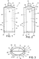
- Figures 1 to 4 an envelope 10 containing a flexible tube 12.
- the flexible tube 12 contains a pasty or liquid product, such as for example a cosmetic cream.
- the tube 12 comprises a body 14 of deformable material, a front end 16 comprising a dispensing orifice, and a rear end 18 closed.
- the body 14 is obtained from a tubular cylinder which is closed at its rear end by folding to form a straight edge constituting the rear end 18 of the tube 12.
- the invention is not limited to such a flexible tube and that the shape and / or dimensions of the tube 12 may be different from that shown in the figures.
- the body of the tube 12 may be of frustoconical or curved main shape.
- the front end 16 of the tube 12 is of similar shape to the main section of the cylinder for producing the body 14 of the tube 12.
- the shape of the front end 16 of the tube is circular.
- the front end 16 of the tube may also be oblong or oval, for example.
- the envelope 10 is intended to cover at least part of the tube 12.
- the casing 10 comprises a body 20 which delimits a volume in which the body 14 of the tube 12 is received, a front end 22 which cooperates with the front end 16 of the tube 12 and a rear end 24 which cooperates with the rear end 18 of the tube 12.
- the envelope 10 is preferably made in one piece, for example by molding a plastic material or any other material.
- the body 20, the front end 22 and the rear end 24 of the casing 10 are parts in one piece.
- the front end 22 of the casing 10 is of associated shape, and preferably complementary to the shape of the front end 16 of the tube 12.
- the front end 16 of the tube 12 is conically shaped, the front end 22 of the casing 10 is also conical.
- the body 20 surrounds the body 14 of the tube 12. It comprises an upper face 26 and a lower face 28, the two upper 26 and lower 28 faces are interconnected by side walls 30. These four walls 26, 28, 30 of the body 20 are distributed around the body 14 of the tube 12.
- each of the walls of the body 20 is defined so that the body 20 envelops the body 14 of the tube 12 as much as possible.
- a clearance is present between the body 14 of the tube 12 and the walls 26, 28, 30 of the body 20 of the casing 10.
- the body 14 of the tube 12 is received without play in the body 20 of the envelope 10, when the tube 12 is filled.
- the material constituting the envelope 10 is a relatively rigid material, in particular, it is more rigid than the material constituting the body 14 of the tube 12.
- This material may be transparent, to allow a user to view inscriptions that would be placed on the walls of the body 14 of the tube 12.
- This material can also be opaque or translucent, allowing on the contrary to mask inscriptions that would be placed on the walls of the body 14 of the tube 12.
- the body 20 of the casing 10 completely surrounds the body 14 of the tube 12, protecting it from external stresses.
- the bottom wall 28 of the casing 10 has an opening 36 through which for example a finger of the user can pass, to press on the body 14 of the tube 12.
- the opening 36 extends along the longitudinal main direction of the envelope 10, from the rear end edge 28a of the bottom wall 28, at which the opening 36 is open, up to approximately the edge front end 28b of the bottom wall 28.
- the front edge 38 of the opening is thus located behind said front end edge 28b of the bottom wall 28, at which the bottom wall is connected to the front end 22 of the envelope 10.
- the shape of the opening 36 is here mainly rectangular, that is to say that the opening has two longitudinal edges 40 located at a distance from one another and a front edge 38.
- the opening 36 is in further open at its rear end.
- the shape of the opening 36 is different, it is for example oblong, with a front edge 38 in the form of a circular arc, or the opening 36 is not open at its rear end which is therefore located at a distance and in front of the rear end edge 28a of the bottom wall 28.
- the dimensions and the shape of the opening 36 are defined to allow the user to press on the entire body 14 of the tube 12, so that it is possible to extract all of the product contained in the tube 12.
- the envelope 10 is open at its rear end 24, which allows the insertion of the tube 12 in the body 20 through the rear end 24 in a main movement of translation longitudinally.
- the rear end 24 of the envelope 10 further comprises means for retaining the tube 12 in the envelope 10.
- These retention means consist according to the invention in two bosses 42 each of which is carried by the rear longitudinal end of the inner face of a side wall 30.
- Each boss 42 protrudes inwardly relative to the inner face 30i associated to form a stop member against which the rear end 18 of the tube 12 abuts longitudinally rearwardly when the tube 12 is in position at the inside the envelope 10.
- the installation of the tube 12 in the envelope 10 is thus done by progressively inserting the tube 12 in the envelope 10 through the opening of the rear end.
- the tube 12 has previously been moved relative to its final position in the envelope 10, so that the insertion is not prevented by the bosses 42 and the tube is not deformed by contact with the bosses 42.
- displacement is performed either by turning the tube 12 about its longitudinal main axis, or by shifting the tube 12 slightly downwards or upwards, relative to its final position, to be offset with respect to the bosses 42.
- the dimensions of the body 20 of the envelope 10 are defined to allow insertion of the tube 12 into the envelope 10. According to the dimensions and the general shape of the tube 12, the tube 12 can then be received in the envelope 10 with some functional game.
- the dimensions of the body of the envelope 10 are also defined to prevent any exit of the tube 12 from the envelope 10 because of the presence of these clearances between the tube 12 and the faces of the body 20.
- the tube 12 is held in position in the casing by an elastic interlocking of the front end 16 of the tube 12 in the front end 22 of the casing 10.
- the resilient interlock is made at the base of the end piece 34 of the tube 12 which is fitted into the central orifice 32 of the front end 22, after the end piece 34 has completely passed through the orifice central 32.
- the endpiece 34 of the tube 12 has an external thread 46 for screwing a stopper (not shown) for sealing the endpiece 34 and the base of the endpiece 34, which is located below this thread 46 has a flange 48 of diameter greater than the outer diameter of the thread.
- the diameter of the central orifice 32 is greater than the diameter of the thread 46 of the tip 34 and is smaller than the external diameter of the collar 48.
- the flange 48 comprises a conical front face 50 defined to facilitate an elastic deformation of the front end 22 of the casing 10 at the central orifice 32, when the end piece is introduced through the central orifice .
- the flange 48 also has a conical rear face 52 which bears against the edge of the central orifice 32 when the end piece 34 is completely inserted.
- the opening angle of the front face 50 is much smaller than the opening angle of the rear face 52, so that the support of the rear face allows the stay in place of the endpiece 34 in the orifice. central 32.
- the tip has a cover 54 which is articulated on the tip 34 and which performs its closure.
- the outer wall of the nozzle 34 is smooth and comprises only a flange 48 similar to that described above, having a conical front face 50 and a conical rear face which bears against the edge of the central orifice 32.
- the invention is not limited to this embodiment of the retaining means by elastic interlocking, and that the retaining means can be arranged at another position in the envelope, for example at the edge of the housing. rear end of the front end 22 of the envelope 10.
- each boss 42 has a groove 44 which is open longitudinally forwards.
- the two grooves 44 of the bosses 42 are intended to receive the flattened rear end 18 of the tube 12.
- the grooves 44 of the bosses 42 perform both the longitudinal retention of the rear end 18 of the tube 12 and the maintenance in vertical displacement upwards or downwards of the rear end 18 of the tube 12.
- the shape and dimensions of the these walls is identical and is defined according to the shape of the tube 12 which is intended to be disposed inside the envelope 10.
- the two walls 26, 28 are of rectangular shape, as for the embodiment of the Figures 1 and 2 .
- the two walls 26, 28 are in the form of an isosceles trapezium, whose parallel sides or bases are formed by the front and rear end edges of the walls 26, 28.
- the large base of this trapezium is thus located at the front end or at the rear end of each wall 26, 28.
- one and / or the other of the two walls 26, 28 is substantially flat.
- one and / or the other of the two walls 26, 28 is substantially curved and is curved towards the outside of the envelope.
- the front end 22 of the casing 10 is of conical shape of revolution, that is to say that its section in a plane perpendicular to the main axis of the casing is circular.
- the section of the front end 22 of the casing 10 is oblong, the direction of the largest dimension of this section may be vertical or horizontal.
- the rear end 24 of the casing 10 is oblong, the large dimension of which is substantially equal to the width of the rear end 18 of the tube 12.
- This oblong shape of the rear end 24 of the envelope 10 applies with any shape and any size of the front end 22 of the envelope 10, as shown in FIG. figure 7 .
- the large dimension of the rear end 24 of the casing 10 is substantially equal to the diameter of the front end 22 of the casing 10 which is circular in shape.
- the large dimension of the rear end 24 of the envelope 10 is smaller than the diameter of the front end 22 of the envelope 10 which is circular in shape.
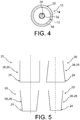
- the front end 22 of the envelope 10 is also oblong, as shown in FIG. figure 6 and its large dimension is greater than the large dimension of the rear end 24 of the envelope 10.
Description
L'invention concerne une enveloppe rigide destinée à recouvrir un tube comprenant un produit liquide ou pâteux, selon le préambule de la revendication 1.The invention relates to a rigid envelope intended to cover a tube comprising a liquid or pasty product, according to the preamble of
Ce tube est souple et se comprime progressivement au fur et à mesure de la distribution du produit. L'enveloppe rigide permet ainsi de conserver un aspect extérieur sensiblement constant, elle permet aussi de protéger le tube contre toute compression involontaire.This tube is flexible and is gradually compressed as and when dispensing the product. The rigid casing thus makes it possible to maintain a substantially constant external appearance, it also makes it possible to protect the tube against any involuntary compression.
Parmi les récipients contenant des produits en crème ou en pâte, il existe un récipient se présentant sous la forme d'un tube flexible que l'on presse pour faire sortir son contenu.Among the containers containing cream or paste products, there is a container in the form of a flexible tube that is pressed to release its contents.
En fonction de l'élasticité ou non de ses parois, le tube peut avoir tendance à reprendre sa forme initiale après le relâchement de la pression qui lui est appliquée. Ce faisant de l'air est aspiré dans le tube pour compenser le volume de produit qui a pu être prélevé.Depending on the elasticity or otherwise of its walls, the tube may tend to return to its original shape after releasing the pressure applied to it. In doing so, air is drawn into the tube to compensate for the volume of product that can be taken.
Certains tubes sont équipés de dispositifs anti retour permettant d'obturer automatiquement l'orifice de distribution, pour empêcher que de l'air ne pénètre dans le tube.Some tubes are equipped with anti-return devices to automatically close the dispensing orifice, to prevent air from entering the tube.
Aussi, le tube se déforme progressivement en s'écrasant, au fur et à mesure des prélèvements de produit.Also, the tube is deformed gradually by crashing, as and when samples of product.
Ces déformations du tube nuisent à l'aspect général du tube.These deformations of the tube adversely affect the general appearance of the tube.
Aussi, une déformation du tube, alors que son embout de distribution est encore obturé, par exemple par un bouchon du type clipsable sur l'embout, produit une surpression du produit dans le tube. Le produit peut alors sortir par l'embout de distribution de manière incontrôlée, ce qui est désagréable pour l'utilisateur.Also, deformation of the tube, while its dispensing tip is still closed, for example by a plug of the type snap on the tip, produces a positive pressure of the product in the tube. The product can then exit through the dispensing nozzle in an uncontrolled manner, which is unpleasant for the user.
Le document
Cette enveloppe est constituée de deux plaques entre lesquelles le tube de produit est placé.This envelope consists of two plates between which the product tube is placed.
Ces deux plaques enveloppent en partie le tube de distribution, pour le protéger d'une grande partie des sollicitations qu'il pourrait subir.These two plates partially envelop the dispensing tube, to protect it from a large part of the stresses it could undergo.
Cependant, cette enveloppe ne recouvre pas totalement le tube de distribution, si bien qu'il est nettement visible depuis l'extérieur, ce qui n'est pas esthétique.However, this envelope does not completely cover the dispensing tube, so that it is clearly visible from the outside, which is not aesthetic.
Aussi, l'enveloppe décrite dans ce document est réalisée en deux parties qui sont mobiles l'une par rapport à l'autre, pour permettre le montage du tube entre celles-ci. La manipulation des deux parties et des moyens pour leur fixation peut s'avérer difficile pour un utilisateur.Also, the envelope described in this document is made in two parts that are movable relative to each other, to allow the mounting of the tube between them. Handling the two parts and means for their attachment can be difficult for a user.
De plus, le tube n'est solidarisé à l'enveloppe qu'à son extrémité au niveau de laquelle l'embout de distribution est situé. Cela réduit donc la stabilité du tube dans l'enveloppe et l'expose à des sollicitations externes.In addition, the tube is secured to the casing at its end at which the dispensing tip is located. This therefore reduces the stability of the tube in the envelope and exposes it to external stresses.
Le document
L'invention propose une enveloppe rigide pour un tube souple comportant les caractéristiques de la revendication 1. En détail, l'enveloppe comporte un corps d'orientation principale longitudinale, qui est constitué d'une paroi supérieure, une paroi inférieure située en vis-à-vis et à distance de la paroi longitudinale supérieure et de deux parois latérales reliant la paroi supérieure avec la paroi inférieure, une tête rigide située à une extrémité longitudinale avant du corps qui comprend un orifice central, elle est réalisée d'une seule pièce à partir d'un matériau rigide.The invention proposes a rigid casing for a flexible tube comprising the features of
La réalisation de l'enveloppe en une seule pièce permet de faciliter son utilisation puisque l'utilisateur n'a pas besoin de manipuler différentes pièces lors du montage du tube souple.The realization of the envelope in one piece makes it easier to use since the user does not need to manipulate different parts during assembly of the flexible tube.
Selon l'invention l'extrémité longitudinale arrière de chaque paroi latérale porte un bossage faisant saillie vers l'intérieur par rapport à la face interne de ladite paroi latérale.According to the invention the rear longitudinal end of each side wall carries a boss projecting inwardly relative to the inner face of said side wall.
De préférence, chaque bossage comporte une rainure ouverte longitudinalement vers l'avant.Preferably, each boss has a groove open longitudinally forwards.
De préférence, la paroi inférieure comporte une ouverture longitudinale qui est ouverte au niveau du bord d'extrémité arrière de la paroi inférieure.Preferably, the bottom wall has a longitudinal opening which is open at the rear end edge of the bottom wall.
De préférence, ladite ouverture comporte un bord avant qui est situé en arrière de bord d'extrémité avant de la paroi inférieure.Preferably, said opening has a leading edge which is located behind the front end edge of the bottom wall.
De préférence, l'une et/ou l'autre de la paroi supérieure et de la paroi inférieure est sensiblement plane.Preferably, one and / or the other of the upper wall and the lower wall is substantially flat.
De préférence, l'une et/ou l'autre de la paroi supérieure et de la paroi inférieure est convexe bombée vers l'extérieur de l'enveloppe.Preferably, one and / or the other of the upper wall and the lower wall is convex curved towards the outside of the envelope.
De préférence, et/ou l'autre de la paroi supérieure et de la paroi inférieure est en forme de trapèze dont les côtés parallèles du trapèze sont formés par les bords d'extrémité longitudinale avant et arrière de ladite paroi supérieure ou ladite paroi inférieure.Preferably, and / or the other of the upper wall and the lower wall is trapezoid-shaped, the parallel sides of the trapezium are formed by the front and rear longitudinal end edges of said upper wall or said lower wall.
L'invention propose aussi un ensemble comportant une enveloppe rigide selon l'invention et un tube souple disposé à l'intérieur de l'enveloppe, ledit tube comportant un corps en matériau déformable, une extrémité avant comprenant un orifice de distribution, et une extrémité arrière fermée, le tube est maintenu en position dans l'enveloppe par un emboitement élastique de l'extrémité avant du tube dans l'extrémité avant de l'enveloppe.The invention also proposes an assembly comprising a rigid envelope according to the invention and a flexible tube disposed inside the envelope, said tube comprising a body of deformable material, a front end comprising a dispensing orifice, and an end rear closed, the tube is held in position in the casing by a resilient interlocking of the front end of the tube in the front end of the casing.
De préférence, la forme du corps de l'enveloppe est similaire à la forme du corps du tube.Preferably, the body shape of the envelope is similar to the shape of the body of the tube.
D'autres caractéristiques et avantages de l'invention apparaîtront à la lecture de la description détaillée qui suit pour la compréhension de laquelle on se reportera aux figures annexées parmi lesquelles :
- la
figure 1 est une représentation schématique en vue de dessus d'une enveloppe selon l'invention ; - la
figure 2 est une vue de dessous de l'enveloppe représentée à lafigure 1 ; - la
figure 3 est une vue en bout de l'extrémité arrière de l'enveloppe représentée à lafigure 1 ; - la
figure 4 est une vue en bout de l'extrémité avant de l'enveloppe représentée à lafigure 1 ; - la
figure 5 montre différentes formes de la face supérieure ou de la face inférieure de l'enveloppe représentée auxfigures 1 et 2 ; - la
figure 6 montre un exemple de forme de l'extrémité avant de l'enveloppe représentée auxfigures 1 et 2 ; - la
figure 7 montre différentes formes de l'extrémité arrière de l'enveloppe représentée auxfigures 1 et 2 ; - la
figure 8 est un détail à plus grande échelle de l'extrémité avant du corps et du tube, montrant les moyens de solidarisation par clipsage ; - la
figure 9 est une vue similaire à celle de lafigure 8 , pour laquelle l'obturation de l'orifice de distribution du tube est effectuée par un couvercle mobile.
- the
figure 1 is a schematic representation in top view of an envelope according to the invention; - the
figure 2 is a bottom view of the envelope shown in thefigure 1 ; - the
figure 3 is an end view of the rear end of the envelope shown atfigure 1 ; - the
figure 4 is an end view of the front end of the envelope shown atfigure 1 ; - the
figure 5 shows different shapes of the upper or lower face of the envelope shown inFigures 1 and 2 ; - the
figure 6 shows an example of the shape of the front end of the envelope shown inFigures 1 and 2 ; - the
figure 7 shows different shapes of the rear end of the envelope shown inFigures 1 and 2 ; - the
figure 8 is a detail on a larger scale of the front end of the body and the tube, showing the fastening means by clipping; - the
figure 9 is a view similar to that of thefigure 8 , for which the closing of the dispensing orifice of the tube is effected by a movable lid.
On a représenté aux
Le tube souple 12 contient un produit pâteux ou liquide, tel que par exemple une crème cosmétique.The
Le tube 12 comporte un corps 14 en matériau déformable, une extrémité avant 16 comprenant un orifice de distribution, et une extrémité arrière 18 fermée.The
Selon un exemple de réalisation, le corps 14 est obtenu à partir d'un cylindre tubulaire qui est fermé au niveau de son extrémité arrière par pliage pour former une arête rectiligne constituant l'extrémité arrière 18 du tube 12.According to an exemplary embodiment, the
Il sera compris que l'invention n'est pas limitée à un tel tube souple et que la forme et/ou les dimensions du tube 12 peuvent être différentes de la représentée aux figures.It will be understood that the invention is not limited to such a flexible tube and that the shape and / or dimensions of the
Par exemple, le corps du tube 12 peut être de forme principale tronconique ou bombée.For example, the body of the
L'extrémité avant 16 du tube 12 est de forme similaire à la section principale du cylindre permettant de réaliser le corps 14 du tube 12. Ici, comme on peut le voir notamment à la
Il sera compris que l'invention n'est pas limitée à cette forme, l'extrémité avant 16 du tube peut aussi être oblongue ou ovale par exemple.It will be understood that the invention is not limited to this form, the
L'enveloppe 10 est destinée à couvrir au moins en partie le tube 12.The
L'enveloppe 10 comporte un corps 20 qui délimite un volume dans lequel le corps 14 du tube 12 est reçu, une extrémité avant 22 qui coopère avec l'extrémité avant 16 du tube 12 et une extrémité arrière 24 qui coopère avec l'extrémité arrière 18 du tube 12.The
L'enveloppe 10 est de préférence, réalisée en une seule pièce, par exemple par moulage d'une matière plastique ou en tout autre matériau.The
Ainsi, le corps 20, l'extrémité avant 22 et l'extrémité arrière 24 de l'enveloppe 10 sont des parties d'une seule pièce.Thus, the
L'extrémité avant 22 de l'enveloppe 10 est de forme associée, et de préférence complémentaire à la forme de l'extrémité avant 16 du tube 12.The
Ici, l'extrémité avant 16 du tube 12 est de forme conique, l'extrémité avant 22 de l'enveloppe 10 est elle aussi de forme conique.Here, the
Elle comporte un orifice central 32 qui est destiné à être traversé par un embout 34 de distribution du tube 12.It comprises a
Le corps 20 entoure le corps 14 du tube 12. Il comporte une face supérieure 26 et une face inférieure 28, les deux faces supérieure 26 et inférieure 28 sont reliées entre elles par des parois latérales 30. Ces quatre parois 26, 28, 30 du corps 20 sont réparties autour du corps 14 du tube 12.The
La forme de chacune des parois du corps 20 est définie pour que le corps 20 enveloppe au maximum le corps 14 du tube 12.The shape of each of the walls of the
Ici, comme on peut le voir aux
Le matériau constitutif de l'enveloppe 10 est un matériau relativement rigide, notamment, il est plus rigide que le matériau constitutif du corps 14 du tube 12.The material constituting the
Ainsi, lorsque le tube 12 est à l'intérieur de l'enveloppe 10, il est protégé contre des pressions extérieures risquant de faire sortir du produit de manière non volontaire.Thus, when the
Ce matériau peut être transparent, pour permettre à un utilisateur de visualiser des inscriptions qui seraient disposées sur les parois du corps 14 du tube 12.This material may be transparent, to allow a user to view inscriptions that would be placed on the walls of the
Ce matériau peut aussi être opaque ou translucide, permettant au contraire de masquer des inscriptions qui seraient disposées sur les parois du corps 14 du tube 12.This material can also be opaque or translucent, allowing on the contrary to mask inscriptions that would be placed on the walls of the
Des inscriptions peuvent en outre être disposées sur les parois 26, 28, 30 du corps 20 de l'enveloppe 10, quel que soit le type de matériau de l'enveloppe, pour remplacer ou compléter les inscriptions du tube 12.Inscriptions may also be arranged on the
Comme on l'a dit plus haut, le corps 20 de l'enveloppe 10 entoure en totalité le corps 14 du tube 12, le protégeant de sollicitations extérieures.As mentioned above, the
Pour permettre à un utilisateur d'exercer une sollicitation sur le corps 14 du tube 12, afin de prélever une certaine quantité du produit contenu, la paroi inférieure 28 de l'enveloppe 10 comporte une ouverture 36 au travers de laquelle par exemple un doigt de l'utilisateur peut passer, pour presser sur le corps 14 du tube 12.To allow a user to exert a bias on the
Ici, comme on peut le voir à la
Le bord avant 38 de l'ouverture est ainsi situé en arrière dudit bord d'extrémité avant 28b de la paroi inférieure 28, au niveau duquel la paroi inférieure est reliée à l'extrémité avant 22 de l'enveloppe 10.The
La forme de l'ouverture 36 est ici principalement rectangulaire, c'est-à-dire que l'ouverture comporte deux bords longitudinaux 40 situés à distance l'un de l'autre et un bord avant 38. L'ouverture 36 est en outre débouchante à son extrémité arrière.The shape of the
A titre de variante de l'invention la forme de l'ouverture 36 est différente, elle est par exemple oblongue, avec un bord avant 38 en forme d'arc de cercle, ou bien l'ouverture 36 est non débouchante à son extrémité arrière, qui est par conséquent située à distance et en avant du bord d'extrémité arrière 28a de la paroi inférieure 28.As a variant of the invention the shape of the
Grâce à cette ouverture 36, un utilisateur peut, en comprimant le corps 14 du tube 12 entre son doigt et la paroi supérieure 26 de l'enveloppe, générer une pression sur le produit contenu dans le tube, pour qu'une certaine partie du produit ressorte par l'embout 34.With this
Les dimensions et la forme de l'ouverture 36 sont définies pour permettre à l'utilisateur de presser sur la totalité du corps 14 du tube 12, pour qu'il soit possible d'extraire la totalité du produit contenu dans le tube 12.The dimensions and the shape of the
L'enveloppe 10 est ouverte au niveau de son extrémité arrière 24, ce qui permet l'insertion du tube 12 dans le corps 20 au travers de cette extrémité arrière 24 selon un mouvement principal de translation longitudinalement.The
L'extrémité arrière 24 de l'enveloppe 10 comporte en outre des moyens pour la rétention du tube 12 dans l'enveloppe 10. Ces moyens de rétention consistent selon l'invention en deux bossages 42 dont chacun est porté par l'extrémité longitudinale arrière de la face interne d'une paroi latérale 30.The
Chaque bossage 42 fait saillie vers l'intérieur par rapport à la face interne 30i associée pour former un élément de butée contre lequel l'extrémité arrière 18 du tube 12 vient buter longitudinalement vers l'arrière lorsque le tube 12 est en position à l'intérieur de l'enveloppe 10.Each
L'installation du tube 12 dans l'enveloppe 10 s'effectue ainsi en insérant progressivement le tube 12 dans l'enveloppe 10 au travers de l'ouverture de l'extrémité arrière.The installation of the
Le tube 12 a au préalable été déplacé par rapport à sa position définitive dans l'enveloppe 10, pour que l'insertion ne soit pas empêchée par les bossages 42 et que le tube ne soit pas déformé par le contact avec les bossages 42. Ce déplacement est effectué soit en tournant le tube 12 autour de son axe principal longitudinal, soit en décalant le tube 12 légèrement vers le bas ou vers le haut, par rapport à sa position définitive, pour être décalé par rapport aux bossages 42.The
Les dimensions du corps 20 de l'enveloppe 10 sont définies pour permettre l'insertion du tube 12 dans l'enveloppe 10. Selon les dimensions et la forme générale du tube 12, le tube 12 peut alors être reçu dans l'enveloppe 10 avec un certain jeu fonctionnel.The dimensions of the
Cependant, les dimensions du corps de l'enveloppe 10 sont aussi définies pour empêcher toute sortie du tube 12 hors de l'enveloppe 10 à cause de la présence de ces jeux entre le tube 12 et les faces du corps 20.However, the dimensions of the body of the
Comme on peut le voir aux
De préférence, l'emboitement élastique est réalisé au niveau de la base de l'embout 34 du tube 12 qui est emboité dans l'orifice central 32 de l'extrémité avant 22, après que l'embout 34 a entièrement traversé l'orifice central 32.Preferably, the resilient interlock is made at the base of the
Par exemple, comme représenté à la figue 8, l'embout 34 du tube 12 comporte un filetage externe 46 permettant le vissage d'un bouchon (non représenté) d'obturation de l'embout 34 et la base de l'embout 34, qui est située au-dessous de ce filetage 46 comporte une collerette 48 de diamètre supérieur au diamètre externe du filetage. Le diamètre de l'orifice central 32 est supérieur au diamètre du filetage 46 de l'embout 34 et est inférieur au diamètre externe de la collerette 48.For example, as shown in FIG. 8, the
Aussi, la collerette 48 comporte une face avant conique 50 définie pour faciliter une déformation élastique de l'extrémité avant 22 de l'enveloppe 10 au niveau de l'orifice central 32, lorsque l'embout est introduit au travers de l'orifice central.Also, the
La collerette 48 comporte aussi une face arrière conique 52 qui vient en appui contre le bord de l'orifice central 32 lorsque l'embout 34 est complètement introduit.The
L'angle d'ouverture de la face avant 50 est très inférieur à l'angle d'ouverture de la face arrière 52, pour que l'appui de la face arrière permette le maintien en place de l'embout 34 dans l'orifice central 32.The opening angle of the
Selon le mode de réalisation représenté à la
La paroi externe de l'embout 34 est lisse et comporte seulement une collerette 48 similaire à celle décrite ci-dessus, comportant une face avant conique 50 et une face arrière conique qui vient en appui contre le bord de l'orifice central 32.The outer wall of the
Ces deux faces coniques coopèrent avec le bord de l'orifice central 32 comme décrit précédemment.These two conical faces cooperate with the edge of the
Il sera compris que l'invention n'est pas limitée à ce mode de réalisation des moyens de retenue par emboitement élastique, et que les moyens de retenue peuvent être disposés à une autre position dans l'enveloppe, par exemple au niveau du bord d'extrémité arrière de l'extrémité avant 22 de l'enveloppe 10.It will be understood that the invention is not limited to this embodiment of the retaining means by elastic interlocking, and that the retaining means can be arranged at another position in the envelope, for example at the edge of the housing. rear end of the
Pour compléter les moyens de maintien par emboitement élastique pour le maintien longitudinal du tube à l'intérieur de l'enveloppe 10, chaque bossage 42 comporte une gorge 44 qui est ouverte longitudinalement vers l'avant.To complete the holding means by elastic interlocking for the longitudinal retention of the tube inside the
Les deux gorges 44 des bossages 42 sont destinées à recevoir l'extrémité arrière 18 aplatie du tube 12.The two
Les gorges 44 des bossages 42 réalisent à la fois le maintien longitudinal de l'extrémité arrière 18 du tube 12 et le maintien en déplacement vertical vers le haut ou vers le bas de l'extrémité arrière 18 du tube 12.The
On a représenté à la
Selon un premier mode de réalisation, les deux parois 26, 28 sont de forme rectangulaire, comme pour le mode de réalisation des
Selon une variante, les deux parois 26, 28 sont en forme de trapèze isocèle, dont les côtés parallèles, ou bases sont formés par les bords d'extrémité avant et arrière des parois 26, 28. La grande base de ce trapèze est ainsi située à l'extrémité avant ou à l'extrémité arrière de chaque paroi 26, 28.According to one variant, the two
En outre, selon un mode de réalisation, l'une et/ou l'autre des deux parois 26, 28 est sensiblement plane.In addition, according to one embodiment, one and / or the other of the two
Selon une variante de réalisation, l'une et/ou l'autre des deux parois 26, 28 est sensiblement cintrée et est bombée vers l'extérieur de l'enveloppe.According to an alternative embodiment, one and / or the other of the two
Selon le mode de réalisation représenté à la
Selon une variante de réalisation représentée à la
Enfin, comme on l'a représenté à la
Cette forme oblongue de l'extrémité arrière 24 de l'enveloppe 10 s'applique avec n'importe quelle forme et n'importe quelle taille de l'extrémité avant 22 de l'enveloppe 10, comme on l'a représenté à la
Selon un premier exemple, la grande dimension de l'extrémité arrière 24 de l'enveloppe 10 est sensiblement égale au diamètre de l'extrémité avant 22 de l'enveloppe 10 qui est de forme circulaire.According to a first example, the large dimension of the
Selon un deuxième exemple, la grande dimension de l'extrémité arrière 24 de l'enveloppe 10 est inférieure au diamètre de l'extrémité avant 22 de l'enveloppe 10 qui est de forme circulaire.According to a second example, the large dimension of the
Selon un troisième exemple, l'extrémité avant 22 de l'enveloppe 10 est elle aussi de forme oblongue, comme représenté à la
Claims (9)
- Rigid shell (10) for a flexible tube (12), comprising:a body (20) having a longitudinal principal orientation, which is made up of an upper wall (26), a lower wall (28) located facing and at a distance from the longitudinal upper wall (26), and two lateral walls (30) connecting the upper wall (26) to the lower wall (28),a rigid head (22) located at a front longitudinal end of the body (20) that comprises a central orifice (32),the shell (10) being made of a single part from a rigid material,characterised in that the back longitudinal end of each lateral wall (30) comprises a boss (42) projecting inwards from the internal face (30i) of said lateral wall (30).
- Rigid shell (10) according to the previous claim, characterised in that each boss (42) comprises a groove open longitudinally forwards.
- Rigid shell (10) according to any one of the previous claims, characterised in that the lower wall (28) comprises a longitudinal opening (36) that is open at the edge of the back end (28a) of the lower wall (28).
- Rigid shell (10) according to the previous claim, characterised in that said opening (36) comprises a front edge located behind the front edge end (28b) of the lower wall (28).
- Rigid shell (10) according to any one of the previous claims, characterised in that either one or both of the upper wall (26) and the lower wall (28), is approximately flat.
- Rigid shell (10) according to any one of claims 1 to 4, characterised in that either one or both of the upper wall (26) and the lower wall (28), is convex towards the outside of the shell (10).
- Rigid shell (10) according to any one of the previous claims, characterised in that either one or both of the upper wall (26) and the lower wall (28), is in the shape of a trapezium, in which the parallel sides of the trapezium are formed from the edges of the front and back longitudinal ends of said upper wall (26) or said lower wall (28).
- Assembly comprising a rigid shell (10) according to any one of the previous claims, and a flexible tube (12) inside the shell (10), said tube (12) comprising a body (14) made of a deformable material, a front end (16) comprising a distribution orifice, and a closed back end (18), the tube (12) is held in position in the shell (10) by an elastic engagement of the front end (16) of the tube (12) in the front end (22) of the shell (10).
- Assembly according to the previous claim, characterised in that the shape of the body (20) of the shell (10) is similar to the shape of the body (14) of the tube (12).
Priority Applications (1)
| Application Number | Priority Date | Filing Date | Title |
|---|---|---|---|
| PL15817887T PL3240733T3 (en) | 2014-12-31 | 2015-12-28 | Rigid shell for a compressible tube |
Applications Claiming Priority (2)
| Application Number | Priority Date | Filing Date | Title |
|---|---|---|---|
| FR1463501A FR3031089B1 (en) | 2014-12-31 | 2014-12-31 | RIGID ENVELOPE FOR COMPRESSIBLE TUBE |
| PCT/EP2015/081276 WO2016107839A1 (en) | 2014-12-31 | 2015-12-28 | Rigid shell for a compressible tube |
Publications (2)
| Publication Number | Publication Date |
|---|---|
| EP3240733A1 EP3240733A1 (en) | 2017-11-08 |
| EP3240733B1 true EP3240733B1 (en) | 2019-02-20 |
Family
ID=52627506
Family Applications (1)
| Application Number | Title | Priority Date | Filing Date |
|---|---|---|---|
| EP15817887.1A Active EP3240733B1 (en) | 2014-12-31 | 2015-12-28 | Rigid shell for a compressible tube |
Country Status (14)
| Country | Link |
|---|---|
| US (1) | US10227164B2 (en) |
| EP (1) | EP3240733B1 (en) |
| JP (1) | JP2018500252A (en) |
| KR (1) | KR20170101917A (en) |
| CN (2) | CN107108079A (en) |
| AU (1) | AU2015373448B2 (en) |
| BR (1) | BR112017013766A2 (en) |
| CA (1) | CA2972139A1 (en) |
| ES (1) | ES2726925T3 (en) |
| FR (1) | FR3031089B1 (en) |
| IL (1) | IL253165B (en) |
| PL (1) | PL3240733T3 (en) |
| RU (1) | RU2017127070A (en) |
| WO (1) | WO2016107839A1 (en) |
Families Citing this family (3)
| Publication number | Priority date | Publication date | Assignee | Title |
|---|---|---|---|---|
| FR3052446B1 (en) | 2016-06-10 | 2018-07-13 | Karine Courtin | DEVICE FOR DISPENSING FLUID PRODUCT |
| KR101812083B1 (en) | 2016-11-21 | 2017-12-26 | 김종호 | Lquid detergent,container |
| US10219793B2 (en) * | 2017-08-04 | 2019-03-05 | Ethicon, Inc. | Delivery systems for flowable substances stored in squeezable containers |
Family Cites Families (13)
| Publication number | Priority date | Publication date | Assignee | Title |
|---|---|---|---|---|
| US1889885A (en) | 1931-05-25 | 1932-12-06 | Ernest E Cullen | Holder for collapsible tubes |
| US2613853A (en) * | 1950-12-18 | 1952-10-14 | Wilmet P Halvorsen | Dispenser with slidable pressure plates for collapsible tubes |
| FR1161905A (en) * | 1956-11-21 | 1958-09-08 | Device for packaging pasty, liquid products, etc., in flexible tubes or cases in rigid envelopes, and for controlling these products | |
| US4326647A (en) * | 1980-05-22 | 1982-04-27 | Pool Dan L | Device for dispensing fluent material from a collapsible container |
| DE4036850A1 (en) * | 1990-11-19 | 1992-05-21 | Henkel Kgaa | Tear opener for inner bag packaging |
| US5346108A (en) * | 1992-10-26 | 1994-09-13 | Pasinski Arthur M | Gaged dispensing apparatus |
| US5277332A (en) * | 1993-02-04 | 1994-01-11 | Isabel Rogers | Multiple dispensing container for viscous materials, cups and toothpaste |
| FR2844773B1 (en) * | 2002-09-24 | 2005-01-28 | Jerome Boumnso | DEVICE FORMING A PACKAGING OF VISCOUS PRODUCTS WITH COMPLETE VIDAGE THROUGH MANUAL PUMPING |
| WO2008102066A1 (en) * | 2007-02-19 | 2008-08-28 | Roger Le Faucheur | Vial for toothpaste tube |
| DE102011100363A1 (en) * | 2010-11-11 | 2012-05-16 | Daniel Andrei | Completely emptied tube |
| WO2012164779A1 (en) * | 2011-06-03 | 2012-12-06 | 東亞合成株式会社 | Outer surface-shaping container and stand for tube container |
| DE102012004510A1 (en) * | 2012-03-06 | 2013-09-12 | Boldt & Co. Vertriebs OHG | Retention device for e.g. vertical holding of thin liquid adhesive tube that is utilized in household applications, has hollow body comprising standing area that is detachably connected with tube, where tube is arranged in standing area |
| FR3011826B1 (en) | 2013-10-10 | 2015-12-25 | Karine Courtin | DEVICE FOR DISPENSING AND PROTECTING FLUID COMPRISING A SLOTTED SHUTTER |
-
2014
- 2014-12-31 FR FR1463501A patent/FR3031089B1/en not_active Expired - Fee Related
-
2015
- 2015-12-28 JP JP2017535001A patent/JP2018500252A/en active Pending
- 2015-12-28 CN CN201580071721.4A patent/CN107108079A/en active Pending
- 2015-12-28 ES ES15817887T patent/ES2726925T3/en active Active
- 2015-12-28 WO PCT/EP2015/081276 patent/WO2016107839A1/en active Application Filing
- 2015-12-28 US US15/540,814 patent/US10227164B2/en not_active Expired - Fee Related
- 2015-12-28 PL PL15817887T patent/PL3240733T3/en unknown
- 2015-12-28 KR KR1020177017505A patent/KR20170101917A/en not_active Application Discontinuation
- 2015-12-28 AU AU2015373448A patent/AU2015373448B2/en not_active Ceased
- 2015-12-28 CN CN202111202264.1A patent/CN113859745A/en active Pending
- 2015-12-28 EP EP15817887.1A patent/EP3240733B1/en active Active
- 2015-12-28 RU RU2017127070A patent/RU2017127070A/en not_active Application Discontinuation
- 2015-12-28 BR BR112017013766-6A patent/BR112017013766A2/en not_active Application Discontinuation
- 2015-12-28 CA CA2972139A patent/CA2972139A1/en not_active Abandoned
-
2017
- 2017-06-25 IL IL253165A patent/IL253165B/en active IP Right Grant
Non-Patent Citations (1)
| Title |
|---|
| None * |
Also Published As
| Publication number | Publication date |
|---|---|
| IL253165B (en) | 2020-09-30 |
| PL3240733T3 (en) | 2019-08-30 |
| CN113859745A (en) | 2021-12-31 |
| WO2016107839A1 (en) | 2016-07-07 |
| KR20170101917A (en) | 2017-09-06 |
| BR112017013766A2 (en) | 2018-02-27 |
| AU2015373448B2 (en) | 2020-09-10 |
| FR3031089B1 (en) | 2017-08-18 |
| IL253165A0 (en) | 2017-08-31 |
| JP2018500252A (en) | 2018-01-11 |
| AU2015373448A1 (en) | 2017-07-13 |
| US20180009575A1 (en) | 2018-01-11 |
| EP3240733A1 (en) | 2017-11-08 |
| CA2972139A1 (en) | 2016-07-07 |
| US10227164B2 (en) | 2019-03-12 |
| CN107108079A (en) | 2017-08-29 |
| RU2017127070A (en) | 2019-01-31 |
| ES2726925T3 (en) | 2019-10-10 |
| FR3031089A1 (en) | 2016-07-01 |
Similar Documents
| Publication | Publication Date | Title |
|---|---|---|
| CA2368052C (en) | Pressurized device fitted with tilt valve | |
| CA2021856C (en) | Dispensing assembly for at least one fluid product, particularly cosmetic or pharmaceutical products | |
| EP0524854B1 (en) | Adjustable valve and dispenser with such a valve | |
| EP1751023B1 (en) | Perfume dispenser | |
| EP1549567B1 (en) | Device forming packaging for viscous products, which can be fully emptied by means of manual pumping | |
| FR2968516A1 (en) | DEVICE FOR PACKAGING A COSMETIC PRODUCT | |
| EP0816253A1 (en) | Device and process for the separate storage of at least two products, for the mixture and distribution of these products | |
| EP1052023A1 (en) | Dispensing head and container provided with such a device | |
| EP1205403B1 (en) | Unit for storing and dispensing a product under pressure | |
| CH674195A5 (en) | ||
| EP3240733B1 (en) | Rigid shell for a compressible tube | |
| FR2729920A1 (en) | BOTTLE BODY AND BOTTLE FOR DISPENSING A PRODUCT | |
| CA2627991A1 (en) | Composite stopper cap | |
| EP0988234B1 (en) | Container equipped with a dispensing nozzle with retractable cover | |
| EP2178415A2 (en) | Device for cosmetic product including a tank and an applicator | |
| OA18345A (en) | Rigid casing for compressible tube. | |
| FR2637512A1 (en) | Device for the automatic delivery of a product or of any object | |
| EP2092985B1 (en) | Container with dip tube | |
| EP3352821B1 (en) | Dispensing assembly having a syringe and a needle guard | |
| EP1284905B1 (en) | Packaging for fluid product with hinge closure | |
| FR2688762A1 (en) | Container obturating device with tamper indicator | |
| FR2791329A1 (en) | Dispensing container for cosmetic gels | |
| EP2983549B1 (en) | Packaging device for a cosmetic product, in particular for a degassing cosmetic product | |
| FR2755672A1 (en) | Sealing of small bottle opening | |
| FR2608563A1 (en) | DROPPER DISPENSER CONTAINER |
Legal Events
| Date | Code | Title | Description |
|---|---|---|---|
| STAA | Information on the status of an ep patent application or granted ep patent |
Free format text: STATUS: THE INTERNATIONAL PUBLICATION HAS BEEN MADE |
|
| PUAI | Public reference made under article 153(3) epc to a published international application that has entered the european phase |
Free format text: ORIGINAL CODE: 0009012 |
|
| STAA | Information on the status of an ep patent application or granted ep patent |
Free format text: STATUS: REQUEST FOR EXAMINATION WAS MADE |
|
| 17P | Request for examination filed |
Effective date: 20170703 |
|
| AK | Designated contracting states |
Kind code of ref document: A1 Designated state(s): AL AT BE BG CH CY CZ DE DK EE ES FI FR GB GR HR HU IE IS IT LI LT LU LV MC MK MT NL NO PL PT RO RS SE SI SK SM TR |
|
| AX | Request for extension of the european patent |
Extension state: BA ME |
|
| DAV | Request for validation of the european patent (deleted) | ||
| DAX | Request for extension of the european patent (deleted) | ||
| GRAP | Despatch of communication of intention to grant a patent |
Free format text: ORIGINAL CODE: EPIDOSNIGR1 |
|
| STAA | Information on the status of an ep patent application or granted ep patent |
Free format text: STATUS: GRANT OF PATENT IS INTENDED |
|
| INTG | Intention to grant announced |
Effective date: 20180907 |
|
| GRAS | Grant fee paid |
Free format text: ORIGINAL CODE: EPIDOSNIGR3 |
|
| GRAA | (expected) grant |
Free format text: ORIGINAL CODE: 0009210 |
|
| STAA | Information on the status of an ep patent application or granted ep patent |
Free format text: STATUS: THE PATENT HAS BEEN GRANTED |
|
| AK | Designated contracting states |
Kind code of ref document: B1 Designated state(s): AL AT BE BG CH CY CZ DE DK EE ES FI FR GB GR HR HU IE IS IT LI LT LU LV MC MK MT NL NO PL PT RO RS SE SI SK SM TR |
|
| REG | Reference to a national code |
Ref country code: GB Ref legal event code: FG4D Free format text: NOT ENGLISH |
|
| REG | Reference to a national code |
Ref country code: CH Ref legal event code: EP |
|
| REG | Reference to a national code |
Ref country code: DE Ref legal event code: R096 Ref document number: 602015025050 Country of ref document: DE |
|
| REG | Reference to a national code |
Ref country code: AT Ref legal event code: REF Ref document number: 1097864 Country of ref document: AT Kind code of ref document: T Effective date: 20190315 |
|
| REG | Reference to a national code |
Ref country code: IE Ref legal event code: FG4D Free format text: LANGUAGE OF EP DOCUMENT: FRENCH |
|
| REG | Reference to a national code |
Ref country code: CH Ref legal event code: NV Representative=s name: BOVARD AG PATENT- UND MARKENANWAELTE, CH |
|
| REG | Reference to a national code |
Ref country code: NL Ref legal event code: FP |
|
| REG | Reference to a national code |
Ref country code: SE Ref legal event code: TRGR |
|
| REG | Reference to a national code |
Ref country code: LT Ref legal event code: MG4D |
|
| REG | Reference to a national code |
Ref country code: NO Ref legal event code: T2 Effective date: 20190220 |
|
| PG25 | Lapsed in a contracting state [announced via postgrant information from national office to epo] |
Ref country code: PT Free format text: LAPSE BECAUSE OF FAILURE TO SUBMIT A TRANSLATION OF THE DESCRIPTION OR TO PAY THE FEE WITHIN THE PRESCRIBED TIME-LIMIT Effective date: 20190620 Ref country code: LT Free format text: LAPSE BECAUSE OF FAILURE TO SUBMIT A TRANSLATION OF THE DESCRIPTION OR TO PAY THE FEE WITHIN THE PRESCRIBED TIME-LIMIT Effective date: 20190220 Ref country code: FI Free format text: LAPSE BECAUSE OF FAILURE TO SUBMIT A TRANSLATION OF THE DESCRIPTION OR TO PAY THE FEE WITHIN THE PRESCRIBED TIME-LIMIT Effective date: 20190220 |
|
| PG25 | Lapsed in a contracting state [announced via postgrant information from national office to epo] |
Ref country code: IS Free format text: LAPSE BECAUSE OF FAILURE TO SUBMIT A TRANSLATION OF THE DESCRIPTION OR TO PAY THE FEE WITHIN THE PRESCRIBED TIME-LIMIT Effective date: 20190620 Ref country code: BG Free format text: LAPSE BECAUSE OF FAILURE TO SUBMIT A TRANSLATION OF THE DESCRIPTION OR TO PAY THE FEE WITHIN THE PRESCRIBED TIME-LIMIT Effective date: 20190520 Ref country code: LV Free format text: LAPSE BECAUSE OF FAILURE TO SUBMIT A TRANSLATION OF THE DESCRIPTION OR TO PAY THE FEE WITHIN THE PRESCRIBED TIME-LIMIT Effective date: 20190220 Ref country code: RS Free format text: LAPSE BECAUSE OF FAILURE TO SUBMIT A TRANSLATION OF THE DESCRIPTION OR TO PAY THE FEE WITHIN THE PRESCRIBED TIME-LIMIT Effective date: 20190220 Ref country code: GR Free format text: LAPSE BECAUSE OF FAILURE TO SUBMIT A TRANSLATION OF THE DESCRIPTION OR TO PAY THE FEE WITHIN THE PRESCRIBED TIME-LIMIT Effective date: 20190521 Ref country code: HR Free format text: LAPSE BECAUSE OF FAILURE TO SUBMIT A TRANSLATION OF THE DESCRIPTION OR TO PAY THE FEE WITHIN THE PRESCRIBED TIME-LIMIT Effective date: 20190220 |
|
| REG | Reference to a national code |
Ref country code: ES Ref legal event code: FG2A Ref document number: 2726925 Country of ref document: ES Kind code of ref document: T3 Effective date: 20191010 |
|
| PG25 | Lapsed in a contracting state [announced via postgrant information from national office to epo] |
Ref country code: CZ Free format text: LAPSE BECAUSE OF FAILURE TO SUBMIT A TRANSLATION OF THE DESCRIPTION OR TO PAY THE FEE WITHIN THE PRESCRIBED TIME-LIMIT Effective date: 20190220 Ref country code: SK Free format text: LAPSE BECAUSE OF FAILURE TO SUBMIT A TRANSLATION OF THE DESCRIPTION OR TO PAY THE FEE WITHIN THE PRESCRIBED TIME-LIMIT Effective date: 20190220 Ref country code: AL Free format text: LAPSE BECAUSE OF FAILURE TO SUBMIT A TRANSLATION OF THE DESCRIPTION OR TO PAY THE FEE WITHIN THE PRESCRIBED TIME-LIMIT Effective date: 20190220 Ref country code: DK Free format text: LAPSE BECAUSE OF FAILURE TO SUBMIT A TRANSLATION OF THE DESCRIPTION OR TO PAY THE FEE WITHIN THE PRESCRIBED TIME-LIMIT Effective date: 20190220 Ref country code: EE Free format text: LAPSE BECAUSE OF FAILURE TO SUBMIT A TRANSLATION OF THE DESCRIPTION OR TO PAY THE FEE WITHIN THE PRESCRIBED TIME-LIMIT Effective date: 20190220 Ref country code: RO Free format text: LAPSE BECAUSE OF FAILURE TO SUBMIT A TRANSLATION OF THE DESCRIPTION OR TO PAY THE FEE WITHIN THE PRESCRIBED TIME-LIMIT Effective date: 20190220 |
|
| REG | Reference to a national code |
Ref country code: DE Ref legal event code: R097 Ref document number: 602015025050 Country of ref document: DE |
|
| PG25 | Lapsed in a contracting state [announced via postgrant information from national office to epo] |
Ref country code: SM Free format text: LAPSE BECAUSE OF FAILURE TO SUBMIT A TRANSLATION OF THE DESCRIPTION OR TO PAY THE FEE WITHIN THE PRESCRIBED TIME-LIMIT Effective date: 20190220 |
|
| PLBE | No opposition filed within time limit |
Free format text: ORIGINAL CODE: 0009261 |
|
| STAA | Information on the status of an ep patent application or granted ep patent |
Free format text: STATUS: NO OPPOSITION FILED WITHIN TIME LIMIT |
|
| 26N | No opposition filed |
Effective date: 20191121 |
|
| PG25 | Lapsed in a contracting state [announced via postgrant information from national office to epo] |
Ref country code: SI Free format text: LAPSE BECAUSE OF FAILURE TO SUBMIT A TRANSLATION OF THE DESCRIPTION OR TO PAY THE FEE WITHIN THE PRESCRIBED TIME-LIMIT Effective date: 20190220 |
|
| PG25 | Lapsed in a contracting state [announced via postgrant information from national office to epo] |
Ref country code: TR Free format text: LAPSE BECAUSE OF FAILURE TO SUBMIT A TRANSLATION OF THE DESCRIPTION OR TO PAY THE FEE WITHIN THE PRESCRIBED TIME-LIMIT Effective date: 20190220 |
|
| REG | Reference to a national code |
Ref country code: BE Ref legal event code: MM Effective date: 20191231 |
|
| PG25 | Lapsed in a contracting state [announced via postgrant information from national office to epo] |
Ref country code: IE Free format text: LAPSE BECAUSE OF NON-PAYMENT OF DUE FEES Effective date: 20191228 Ref country code: LU Free format text: LAPSE BECAUSE OF NON-PAYMENT OF DUE FEES Effective date: 20191228 |
|
| REG | Reference to a national code |
Ref country code: AT Ref legal event code: UEP Ref document number: 1097864 Country of ref document: AT Kind code of ref document: T Effective date: 20190220 |
|
| PG25 | Lapsed in a contracting state [announced via postgrant information from national office to epo] |
Ref country code: BE Free format text: LAPSE BECAUSE OF NON-PAYMENT OF DUE FEES Effective date: 20191231 |
|
| PG25 | Lapsed in a contracting state [announced via postgrant information from national office to epo] |
Ref country code: CY Free format text: LAPSE BECAUSE OF FAILURE TO SUBMIT A TRANSLATION OF THE DESCRIPTION OR TO PAY THE FEE WITHIN THE PRESCRIBED TIME-LIMIT Effective date: 20190220 |
|
| PG25 | Lapsed in a contracting state [announced via postgrant information from national office to epo] |
Ref country code: HU Free format text: LAPSE BECAUSE OF FAILURE TO SUBMIT A TRANSLATION OF THE DESCRIPTION OR TO PAY THE FEE WITHIN THE PRESCRIBED TIME-LIMIT; INVALID AB INITIO Effective date: 20151228 Ref country code: MT Free format text: LAPSE BECAUSE OF FAILURE TO SUBMIT A TRANSLATION OF THE DESCRIPTION OR TO PAY THE FEE WITHIN THE PRESCRIBED TIME-LIMIT Effective date: 20190220 |
|
| PGFP | Annual fee paid to national office [announced via postgrant information from national office to epo] |
Ref country code: AT Payment date: 20211123 Year of fee payment: 7 Ref country code: FR Payment date: 20211231 Year of fee payment: 7 Ref country code: NL Payment date: 20211116 Year of fee payment: 7 Ref country code: MC Payment date: 20211124 Year of fee payment: 7 Ref country code: GB Payment date: 20211220 Year of fee payment: 7 Ref country code: SE Payment date: 20211221 Year of fee payment: 7 Ref country code: NO Payment date: 20211125 Year of fee payment: 7 Ref country code: DE Payment date: 20211210 Year of fee payment: 7 |
|
| PGFP | Annual fee paid to national office [announced via postgrant information from national office to epo] |
Ref country code: IT Payment date: 20211214 Year of fee payment: 7 Ref country code: CH Payment date: 20211223 Year of fee payment: 7 |
|
| PGFP | Annual fee paid to national office [announced via postgrant information from national office to epo] |
Ref country code: PL Payment date: 20211129 Year of fee payment: 7 |
|
| PGFP | Annual fee paid to national office [announced via postgrant information from national office to epo] |
Ref country code: ES Payment date: 20220104 Year of fee payment: 7 |
|
| PG25 | Lapsed in a contracting state [announced via postgrant information from national office to epo] |
Ref country code: MK Free format text: LAPSE BECAUSE OF FAILURE TO SUBMIT A TRANSLATION OF THE DESCRIPTION OR TO PAY THE FEE WITHIN THE PRESCRIBED TIME-LIMIT Effective date: 20190220 |
|
| REG | Reference to a national code |
Ref country code: DE Ref legal event code: R119 Ref document number: 602015025050 Country of ref document: DE |
|
| REG | Reference to a national code |
Ref country code: NO Ref legal event code: MMEP |
|
| REG | Reference to a national code |
Ref country code: CH Ref legal event code: PL |
|
| REG | Reference to a national code |
Ref country code: SE Ref legal event code: EUG |
|
| REG | Reference to a national code |
Ref country code: NL Ref legal event code: MM Effective date: 20230101 |
|
| REG | Reference to a national code |
Ref country code: AT Ref legal event code: MM01 Ref document number: 1097864 Country of ref document: AT Kind code of ref document: T Effective date: 20221228 |
|
| GBPC | Gb: european patent ceased through non-payment of renewal fee |
Effective date: 20221228 |
|
| PG25 | Lapsed in a contracting state [announced via postgrant information from national office to epo] |
Ref country code: NL Free format text: LAPSE BECAUSE OF NON-PAYMENT OF DUE FEES Effective date: 20230101 |
|
| PG25 | Lapsed in a contracting state [announced via postgrant information from national office to epo] |
Ref country code: SE Free format text: LAPSE BECAUSE OF NON-PAYMENT OF DUE FEES Effective date: 20221229 Ref country code: NO Free format text: LAPSE BECAUSE OF NON-PAYMENT OF DUE FEES Effective date: 20221231 Ref country code: LI Free format text: LAPSE BECAUSE OF NON-PAYMENT OF DUE FEES Effective date: 20221231 Ref country code: GB Free format text: LAPSE BECAUSE OF NON-PAYMENT OF DUE FEES Effective date: 20221228 Ref country code: DE Free format text: LAPSE BECAUSE OF NON-PAYMENT OF DUE FEES Effective date: 20230701 Ref country code: CH Free format text: LAPSE BECAUSE OF NON-PAYMENT OF DUE FEES Effective date: 20221231 Ref country code: AT Free format text: LAPSE BECAUSE OF NON-PAYMENT OF DUE FEES Effective date: 20221228 |
|
| PG25 | Lapsed in a contracting state [announced via postgrant information from national office to epo] |
Ref country code: FR Free format text: LAPSE BECAUSE OF NON-PAYMENT OF DUE FEES Effective date: 20221231 |
|
| PG25 | Lapsed in a contracting state [announced via postgrant information from national office to epo] |
Ref country code: IT Free format text: LAPSE BECAUSE OF NON-PAYMENT OF DUE FEES Effective date: 20221228 |
|
| REG | Reference to a national code |
Ref country code: ES Ref legal event code: FD2A Effective date: 20240202 |