EP1549567B1 - Device forming packaging for viscous products, which can be fully emptied by means of manual pumping - Google Patents
Device forming packaging for viscous products, which can be fully emptied by means of manual pumping Download PDFInfo
- Publication number
- EP1549567B1 EP1549567B1 EP03798217A EP03798217A EP1549567B1 EP 1549567 B1 EP1549567 B1 EP 1549567B1 EP 03798217 A EP03798217 A EP 03798217A EP 03798217 A EP03798217 A EP 03798217A EP 1549567 B1 EP1549567 B1 EP 1549567B1
- Authority
- EP
- European Patent Office
- Prior art keywords
- reservoir
- orifice
- neck
- parts
- packaging
- Prior art date
- Legal status (The legal status is an assumption and is not a legal conclusion. Google has not performed a legal analysis and makes no representation as to the accuracy of the status listed.)
- Expired - Lifetime
Links
- 238000004806 packaging method and process Methods 0.000 title claims abstract description 32
- 238000005086 pumping Methods 0.000 title claims description 9
- 210000003813 thumb Anatomy 0.000 claims description 9
- 235000011837 pasties Nutrition 0.000 claims description 5
- 238000013022 venting Methods 0.000 claims description 4
- 238000004026 adhesive bonding Methods 0.000 claims description 2
- 210000003739 neck Anatomy 0.000 claims 10
- 230000000903 blocking effect Effects 0.000 claims 2
- 230000011664 signaling Effects 0.000 claims 1
- 230000006835 compression Effects 0.000 abstract description 3
- 238000007906 compression Methods 0.000 abstract description 3
- 239000000047 product Substances 0.000 description 31
- 208000031968 Cadaver Diseases 0.000 description 15
- 238000009826 distribution Methods 0.000 description 10
- 210000003811 finger Anatomy 0.000 description 4
- 238000003466 welding Methods 0.000 description 4
- 239000003292 glue Substances 0.000 description 3
- 238000007789 sealing Methods 0.000 description 3
- 229940082150 encore Drugs 0.000 description 2
- 238000001125 extrusion Methods 0.000 description 2
- 239000007788 liquid Substances 0.000 description 2
- KRQUFUKTQHISJB-YYADALCUSA-N 2-[(E)-N-[2-(4-chlorophenoxy)propoxy]-C-propylcarbonimidoyl]-3-hydroxy-5-(thian-3-yl)cyclohex-2-en-1-one Chemical compound CCC\C(=N/OCC(C)OC1=CC=C(Cl)C=C1)C1=C(O)CC(CC1=O)C1CCCSC1 KRQUFUKTQHISJB-YYADALCUSA-N 0.000 description 1
- 235000005921 Cynara humilis Nutrition 0.000 description 1
- 240000002228 Cynara humilis Species 0.000 description 1
- 241001080024 Telles Species 0.000 description 1
- 239000000853 adhesive Substances 0.000 description 1
- 230000001070 adhesive effect Effects 0.000 description 1
- 230000000295 complement effect Effects 0.000 description 1
- 230000003750 conditioning effect Effects 0.000 description 1
- 239000008278 cosmetic cream Substances 0.000 description 1
- 230000000694 effects Effects 0.000 description 1
- 238000000605 extraction Methods 0.000 description 1
- 235000013305 food Nutrition 0.000 description 1
- 239000000499 gel Substances 0.000 description 1
- 238000003780 insertion Methods 0.000 description 1
- 230000037431 insertion Effects 0.000 description 1
- 238000005304 joining Methods 0.000 description 1
- 239000012263 liquid product Substances 0.000 description 1
- 238000000034 method Methods 0.000 description 1
- 239000003973 paint Substances 0.000 description 1
- 239000006072 paste Substances 0.000 description 1
- 230000035515 penetration Effects 0.000 description 1
- 230000002093 peripheral effect Effects 0.000 description 1
- 239000004033 plastic Substances 0.000 description 1
- 229920003023 plastic Polymers 0.000 description 1
- 238000007747 plating Methods 0.000 description 1
- -1 polyethylene part Polymers 0.000 description 1
- 238000003825 pressing Methods 0.000 description 1
- 230000000750 progressive effect Effects 0.000 description 1
- 238000011084 recovery Methods 0.000 description 1
- 238000010079 rubber tapping Methods 0.000 description 1
- 239000002453 shampoo Substances 0.000 description 1
- 239000012815 thermoplastic material Substances 0.000 description 1
- 239000000606 toothpaste Substances 0.000 description 1
- 238000004804 winding Methods 0.000 description 1
Images


Classifications
-
- B—PERFORMING OPERATIONS; TRANSPORTING
- B65—CONVEYING; PACKING; STORING; HANDLING THIN OR FILAMENTARY MATERIAL
- B65D—CONTAINERS FOR STORAGE OR TRANSPORT OF ARTICLES OR MATERIALS, e.g. BAGS, BARRELS, BOTTLES, BOXES, CANS, CARTONS, CRATES, DRUMS, JARS, TANKS, HOPPERS, FORWARDING CONTAINERS; ACCESSORIES, CLOSURES, OR FITTINGS THEREFOR; PACKAGING ELEMENTS; PACKAGES
- B65D83/00—Containers or packages with special means for dispensing contents
- B65D83/0055—Containers or packages provided with a flexible bag or a deformable membrane or diaphragm for expelling the contents
-
- B—PERFORMING OPERATIONS; TRANSPORTING
- B65—CONVEYING; PACKING; STORING; HANDLING THIN OR FILAMENTARY MATERIAL
- B65D—CONTAINERS FOR STORAGE OR TRANSPORT OF ARTICLES OR MATERIALS, e.g. BAGS, BARRELS, BOTTLES, BOXES, CANS, CARTONS, CRATES, DRUMS, JARS, TANKS, HOPPERS, FORWARDING CONTAINERS; ACCESSORIES, CLOSURES, OR FITTINGS THEREFOR; PACKAGING ELEMENTS; PACKAGES
- B65D2231/00—Means for facilitating the complete expelling of the contents
- B65D2231/001—Means for facilitating the complete expelling of the contents the container being a bag
Definitions
- the present invention generally relates to flexible packages which are emptied by compression, such as tubes, and allows complete emptying without deformation of the packaging, liquid products, viscous and pasty such as cosmetic creams, gels, shampoos, paints, toothpastes, food products, craft pastes etc.
- the prior art provides deformable flexible packages integrally compressible so as to recover the maximum product by pressure.
- the device as presented in the document FR2792615 requires a tedious and energetic handling during the recovery of the last drops of products. Indeed after winding of the body of the packaging, it is still necessary to crush the head to extract the remaining product.
- the device as presented in the document FR2796622 allows you to recover using a tool or a finger the last drops of products in the neck of the dispensing head. As in the previous example, this device is neither practical nor easy to use.
- the prior art proposes devices for extracting the product from a packaging by a dispenser.
- the device as presented in the document FR2800718 a package provided with a flexible pouch containing the pumped product has the disadvantage of only delivering small doses with each pressure on the dispenser.
- the document EP 505611 discloses a device forming a package according to the preamble of claim 1.
- the assembled packaging according to the invention according to claim 1 overcomes these disadvantages.
- it provides a solution for integral emptying by compression pumping of the body, without definitive deformation of the packaging.
- the loss of product is of the order of 1% to 3%.
- the emptying is done with the same comfort and ease as when it was full and this regardless of the position in which the packaging was located before use, and whatever its position at moment of emptying.
- the packaging presented is a tube.
- the device according to the invention can also be used and emptied exactly as a traditional conditioning by successive pressures without using the vent orifice (c5). At any moment of the emptying, it is possible to choose whether to use the vent hole or not. The best result is obtained, especially at the end of emptying, with the use of this vent orifice.
- the packaging is emptied by pumping when the pressure of the fingers on the body is done while the thumb obstructs the venting port (c5) of the body (C).
- the air between the body (C) and the retractable flexible bag (B) is compressed and retracted by inverting this flexible bag into the interior of the body (A) and thus pushes the product towards the distribution channel (a2) cf . figure 12 . In its empty position the flexible bag (B) is retracted as far as possible against the walls of the tank (A) cf. figure 13 . There are no more products in the packaging and it still keeps its initial appearance as if it was full.
- the vent hole (c'5) located on the body (C '), can be positioned at a distance (Lo) from the bottom (c'3) at most equal to the length of the thumb so that naturally the thumb comes to press on this orifice, with as an example: Lo ⁇ Lc '/ 2'.
- the assembly C 'and B forms a sealed package for receiving the product whose filling is effected by the distribution channel (c'6) of the body (C').
- the device is an assembly of four parts ((A), (B), (C), (D));
- a packaging tube For the particular case of a packaging tube, it comprises a reservoir (A) fig.4 whose characteristics are the same as a traditional tube in its upper half. It is composed at one end of a neck (a1), provided with a distribution channel (a2) connected by a frustoconical shoulder (a3) to a tubular skirt (a4) which may be made of thermoplastic material and obtained by extrusion, and at the other end (a5) provided with an opening.
- the tubular skirt (a4) may have a length (La), defined by the end (a5) and the junction between the frustoconical shoulder (a3) and the skirt tubular (a4), less than (Lc) / 2, where (Lc) is the distance defined by the junction (c4) and (c2) and the base (c3) of the body (C).
- the device comprises a cylindrical flexible pouch polyethylene part (B) whose open end (b2) is advantageously fixed by heat sealing on the opening (a5) of the tank (A).
- the assembly zone (Las) defined by the connection portion between the reservoir (A) and the pocket (B), is in a preferred embodiment within the wall of the tank (A).
- the figure 13 shows how, during the complete emptying of the packaging the bag (B) is completely retracted by turning and plated on the inner walls of the tank (A).
- this phenomenon is optimized when the length (Lap) of the pocket (B), defined by the end (a5) and the junction (b1) and (b3), is equal to the length (La) of the reservoir (A) , with the diameters (Db) of the pocket (B) and (Da) of the reservoir (A) equal according to the figure 2 .
- the base of the flexible pouch (b1) is advantageously conical with the same angle ( ⁇ b) as that of the internal frustoconical shoulder of the reservoir (A) ( ⁇ a), this makes it possible to give, at the end of pumping, a good plating of the flexible bag against the shoulder of the tank (A) and expel the maximum product to the distribution channel (a2).
- the reservoir assembly (A) and flexible bag (B) form a sealed package for receiving the product which is filled by the distribution channel (a2).
- the device comprises a body (C) cf. fig.4 which is actually a traditional tube which, instead of having a collar at the top, has an orifice.
- This tube comprises a frustoconical shoulder (c4), provided with an orifice (c1), connecting to the skirt as for a traditional tube.
- the sealing of the assembly can be, in a preferred embodiment, guaranteed by cylindrical seals (1) or by tight bonding of the body (C) and the tank (A) at the neck (c4) and ( a3).
- the fixing and maintaining the assembly (A) and (B) in the body (C) may be, by way of non-limiting example, performed either by welding or by snapping the head (a1) with the orifice (c1) either by tightening a pouring cap on the head (a1), or by tightening a thin plastic nut on the head (a1), or by snapping a washer on the head (a1) or by screwing (a1) through the orifice (c1) then provided with a thread.
- the body (C) cf. fig.4 & 5 comprises an elongated tubular skirt (c2), obtained by extrusion, the other end (c3) of which is obstructed, in the case of a tube, after assembly, by crushing along an axis XX 'perpendicular to the axis of the tube .
- the inside diameter (Dc) of the body (C) is adapted and greater than the maximum outside dimensions (DA) of the tank (A).
- the body (C) has on its skirt (c2) a lateral vent orifice (c5) situated, for information and without limitation, at a distance (LO) less than LC / 2 of the end (c3).
- the diameter, by way of non-limiting example, of the orifice (c5) may be from 1 to 6 millimeters in diameter.
- the orifice (c5), (c'5) is advantageously and for the comfort of the user positioned in an ergonomic area of the hand so that the thumb is naturally placed on the orifice during emptying of the packaging.
- the location of the orifice (c5), (c'5) can be highlighted by an adhesive patch so that it is located quickly visually and touch.
- the orifice (c5), (c'5) may be provided with a valve, and may be, in this particular case, located anywhere on the body (C), this frees the user from the pressing operation on this orifice (c5) to extract the product.
- the four elements of the invention are assembled in the following order: Welding assembly of the flexible bag (B) and the tank (A), then insertion and fixation of the assembly (A) and (B) in the body (C). Finally, the body (C) is obstructed at its end of large opening (c3) by crushing. The cap (D) is fixed on the neck (a1) protruding from the body.
- the cylindrical and tubular shape of the body (C) is not limiting, the latter can take all the geometric shapes of the type, bottle obstructed by a flat bottom at the end (c3), two-piece shell cf. fig.10 .
- this system can easily be adapted to different geometrical shapes while respecting the complementary character of parts (A), (B), (C), (D).
- the subject of the invention is a device for integral emptying of compressible packaging of liquid, viscous and pasty products.
- the invention relates to a packaging for the complete emptying of compressible containers by finger pressure on their body. It consists of four parts: a body (C) having a vent hole, a tank (A) having an expulsion port and a flexible bag (B) and a a cap (D).
- the flexible bag retracts and turns completely, until it is pressed against the inside wall of the tank.
- the user exerts several pressures on the body (C) of the packaging by obstructing with a finger the vent hole (c5), all the product contained in the flexible bag is expelled gradually and effortlessly, by compressing the air contained in the body.
- the device according to the invention is suitable for all compressible packages of liquid, viscous or pasty products
Abstract
Description
La présente invention concerne d'une manière générale les conditionnements souples qui se vident par compression, tel que les tubes, et permet la vidange intégrale sans déformation du conditionnement, de produits liquides, visqueux et pâteux tels que les crèmes cosmétiques, les gels, les shampooings, les peintures, les pâtes dentifrices, produits alimentaires, les pâtes de bricolages etc..The present invention generally relates to flexible packages which are emptied by compression, such as tubes, and allows complete emptying without deformation of the packaging, liquid products, viscous and pasty such as cosmetic creams, gels, shampoos, paints, toothpastes, food products, craft pastes etc.
Traditionnellement le vidage d'un conditionnement compressible est effectué par pressions successives. Plus on avance dans le vidage, plus il faut appuyer fort sur le corps du conditionnement et le déformer. Lorsque le conditionnement commence à se vider, il faut le renverser pour amener le produit restant vers l'orifice. Lorsque le conditionnement est presque vide, il faut même le secouer fermement, le tordre ou le découper pour extraire la dernière goutte de produit. Idéalement, pour une meilleure expulsion du produit, il faut laisser le conditionnement se reposer, tête vers le bas pour que le produit se soit écoulé vers son orifice, avant utilisation.Traditionally, the emptying of a compressible packaging is carried out by successive pressures. The more we advance in the dump, the more we have to press hard on the body of the packaging and deform it. When the packaging begins to empty, it must be reversed to bring the remaining product to the orifice. When the packaging is almost empty, you must even shake it firmly, twist it or cut it to extract the last drop of product. Ideally, for a better expulsion of the product, it is necessary to let the packaging rest, head down so that the product has flowed to its orifice, before use.
En général, il est difficilement possible de vider l'intégralité du contenu d'un conditionnement tel qu'un tube traditionnel, ce qui a pour effet une perte d'environ 10% à 15% du produit.In general, it is hardly possible to empty the entire contents of a packaging such as a traditional tube, which results in a loss of about 10% to 15% of the product.
On trouve notamment dans l'art antérieur, différents types de techniques pour optimiser la vidange totale de conditionnements souples pour produits visqueux.In the prior art, there are various types of techniques for optimizing the total emptying of flexible packages for viscous products.
Des dispositifs s'adaptant sur les tubes souples permettent de maintenir le produit restant dans le conditionnement toujours dans la partie supérieure du tube proche de l'orifice d'extraction. Le dispositif tel que présenté dans le document
L'art antérieur propose des conditionnements souples déformables intégralement compressibles de manière à récupérer le maximum de produit par pression. Le dispositif tel que présenté dans le document
L'art antérieur propose des dispositifs d'extraction du produit d'un conditionnement par un distributeur. Le dispositif tel que présenté dans le document
Le document
Le conditionnement assemblé selon l'invention conformément à la revendication 1 permet de remédier à ces inconvénients. Il apporte, dans ce contexte, une solution de vidange intégrale par pompage par compression du corps, sans déformation définitive du conditionnement. La perte de produit est de l'ordre de 1% à 3%. Indépendamment de la quantité de produit dans le conditionnement, le vidage se fait avec le même confort et la même facilité que lorsqu'il était plein et ceci quelle que soit la position dans laquelle se trouvait le conditionnement avant utilisation, et quelque soit sa position au moment du vidage. A titre non limitatif, le conditionnement présenté est un tube.The assembled packaging according to the invention according to claim 1 overcomes these disadvantages. In this context, it provides a solution for integral emptying by compression pumping of the body, without definitive deformation of the packaging. The loss of product is of the order of 1% to 3%. Regardless of the amount of product in the packaging, the emptying is done with the same comfort and ease as when it was full and this regardless of the position in which the packaging was located before use, and whatever its position at moment of emptying. By way of non-limiting example, the packaging presented is a tube.
Le dispositif formant un conditionnement assemblé comporte quatre parties (A), (B), (C), (D)
- La pièce (A) (
fig.4 ) dite réservoir pourvue d'une extrémité comportant un épaulement tronconique (a3) surmonté d'un col (a1), comprenant un canal de distribution (a2), et sur son autre extrémité (a5), une ouverture. - La pièce (B) (
fig.4 ) dite poche souple rétractable comportant une extrémité (b1) conique et une autre extrémité (b2) ouverte, et en ce que les pièces (A) et (B) sont soudées par leurs extrémités respectives ouvertes (a5) et (b2), l'ensemble des pièces (A) et (B) forme ainsi un conditionnement étanche destiné à recevoir le produit dont le remplissage s'effectue par le canal de distribution (a2) du réservoir (A). - La Pièce (C) (
fig.4 ) dite corps pourvue d'un orifice latéral de mise à l'air libre (c5) obturable manuellement de sorte à constituer, lors de la pression sur l'ensemble, un "système de pompage " dont une extrémité (c3) est obstruée par écrasement, et l'autre extrémité comporte une épaulement tronconique (c4) comprenant une ouverture (c1), et en ce que avant obstruction de l'extrémité (c3), l'ensemble de pièces (A) et (B) s'ajuste dans le corps (C) en butée sur le raccord de l'épaulement tronconique (c4) d'une manière étanche. - La pièce (D) (
fig.4 ) dite capuchon destiné à venir obturer le col (a1) de l'assemblage pièces (A) (B) (C).
- The piece (A) (
fig.4 ) said tank provided with an end having a frustoconical shoulder (a3) surmounted by a neck (a1), comprising a distribution channel (a2), and on its other end (a5), an opening. - The piece (B) (
fig.4 ) said retractable flexible pouch having a conical end (b1) and another end (b2) open, and in that the parts (A) and (B) are welded by their respective open ends (a5) and (b2), all parts (A) and (B) thus forms a sealed package for receiving the product whose filling is effected by the distribution channel (a2) of the reservoir (A). - Room (C) (
fig.4 ) said body provided with a lateral vent orifice (c5) closable manually so as to constitute, during the pressure on the assembly, a "pumping system" whose end (c3) is obstructed by crushing, and the other end comprises a frustoconical shoulder (c4) comprising an opening (c1), and in that before obstruction of the end (c3), the set of parts (A) and (B) fits into the body (C) abutting the connection of the frustoconical shoulder (c4) in a sealed manner. - The piece (D) (
fig.4 ) said cap for closing the neck (a1) of the assembly parts (A) (B) (C).
Le dispositif selon l'invention peut être aussi utilisé et vidé exactement comme un conditionnement traditionnel par pressions successives sans utilisation de l'orifice de mise à l'air libre (c5). A tout moment du vidage on peut choisir d'utiliser ou non l'orifice de mise à l'air libre. Le meilleur résultat étant obtenu, notamment en fin de vidage, avec l'utilisation de cet orifice de mise à l'air libre. En effet, le conditionnement se vide par pompage lorsque la pression des doigts sur le corps se fait alors que le pouce obstrue l'orifice de mise à l'air libre (c5) du corps (C). L'air compris entre le corps (C) et la poche souple rétractable (B) est comprimé et rétracte par retournement cette poche souple dans l'intérieur du corps(A) et ainsi repousse le produit vers le canal de distribution (a2) cf.
Selon un premier mode particulier de réalisation (
- la piéce (A') dite réservoir est ouverte aux deux extrémités, et sur l'extrémité (a'5), la poche souple rétractable (B) est soudée par son extrémité (b2),
- la pièce (C') dite corps est constituée d'une jupe tubulaire (C'2) dont, une extrémité (c'3) est obstruée par écrasement, et l'autre extrémité comporte un épaulement tronconique (c'4) avec un col muni d'un pas de vis, comprenant un canal de distribution (c'6) obstrué par le capuchon(D), et en ce que avant obstruction de l'extrémité (c'3), l'ensemble de pièces (A') et (B) s'ajuste dans ledit corps (C') en butée sur le raccord de l'épaulement tronconique (c4') d'une manière étanche par collage.
- the piece (A ') said tank is open at both ends, and on the end (a'5), the retractable flexible bag (B) is welded by its end (b2),
- said body (C ') is constituted by a tubular skirt (C'2) whose end (c'3) is obstructed by crushing, and the other end comprises a frustoconical shoulder (c'4) with a neck with a thread, comprising a dispensing channel (c'6) obstructed by the cap (D), and in that before obstruction of the end (c'3), the set of parts (A ') and (B) fits in said body (C') abutting the connection of the frustoconical shoulder (c4 ') in a sealed manner by gluing.
Selon un deuxième mode particulier de réalisation (
L'extrémité ouverte (b2) de la poche souple(B) est directement soudée sur une zone d'assemblage de quelques millimètres (Las) à l'intérieur de la paroi interne du corps (C'), avec à titre d'exemple: La=Lap<Lc'/2 où (La) représente la distance entre la jonction (c'4)(c'2) et la fin de la zone d'assemblage (Las), où (Lap) représente la partie apparente rétractable de la poche souple comprise entre la fin de la zone d'assemblage (Las) et le début de l'extrémité conique (b1), où (Lc') représente la distance entre la jonction (c'4)(c'2) et le fond (c'3). L'orifice de mise à l'air libre(c'5), situé sur le corps (C'), peut-être positionné à une distance (Lo) du fond (c'3) au plus égale à la longueur du pouce de sorte que naturellement le pouce vienne appuyer sur cette orifice, avec à titre d'exemple: Lo<Lc'/2'. L'ensemble C' et B forme un conditionnement étanche destiné à recevoir le produit dont le remplissage s'effectue par le canal de distribution (c'6) du corps (C').The open end (b2) of the flexible pouch (B) is directly welded to an assembly area of a few millimeters (Las) inside the inner wall of the body (C '), with as an example : La = Lap <Lc '/ 2 where (La) represents the distance between the junction (c'4) (c'2) and the end of the assembly zone (Las), where (Lap) represents the retractable apparent part of the flexible pocket between the end of the joining zone (Las) and the beginning of the conical end (b1), where (Lc ') represents the distance between the junction (c'4) (c'2) and the bottom (c'3). The vent hole (c'5), located on the body (C '), can be positioned at a distance (Lo) from the bottom (c'3) at most equal to the length of the thumb so that naturally the thumb comes to press on this orifice, with as an example: Lo <Lc '/ 2'. The assembly C 'and B forms a sealed package for receiving the product whose filling is effected by the distribution channel (c'6) of the body (C').
Selon d'autres modes de réalisation :
- Le dispositif peut comporter, en variante, sur le corps (C)(C') un orifice de mise à l'air libre muni d'une valve. Lors de la pression de l'utilisateur sur le corps du conditionnement pour extraire le produit, la valve obstrue l'orifice et maintient l'air dans le corps (C), (C') et ceci sans que l'utilisateur n'ai besoin de positionner son pouce sur l'orifice. La valve pourra donc être positionnée sur n'importe quel endroit de la surface (c2), (c'2) du corps (C), (C').
- Le col (a1)
fig.4 et (c'1)fig.6 peut être à titre non limitatif de formes coniques ou cylindriques, et comporter tout système de fixation du capuchon (D) par vissage ou encliquetage. - L'assemblage du réservoir (A) avec le corps (C) (cf.
figure 4 ) par le passage du col (a1) à travers l'orifice (c1) peut s'effectuer par vissage au lieu d'un soudage, en taraudant (c1) et adaptant le diamètre (d1) du corps (C) au diamètre (d2) du pas de vis du col (a1) du réservoir (A). Le serrage des deux pièces l'une contre l'autre aura pour effet d'écraser des joints d'étanchéités (1) ou la colle disposées entre les deux épaulement (a3) et (c4). - L'assemblage du réservoir (A) et du corps (C) (cf.
figure 4 ), peut en variante, être réalisé par tout système d'encliquetage du col (a1) du réservoir (A) à travers l'orifice (c1) du corps (C). L'étanchéité est obtenue également par les joints (1) ou par la colle au niveau des deux épaulements (a3) et (c4). - L'assemblage des pièces (A) et (C) (cf.
figure 4 ) peut encore se faire en adaptant après passage du col (a1) du réservoir (A) à travers l'orifice (c1) du corps (C), un écrou ou une rondelle qui viendra respectivement se visser ou s'encliqueter sur le col (a1) et ainsi serrer les deux pièces l'une contre l'autre. L'étanchéité est obtenue également par les joints (1) ou par la colle au niveau des deux épaulements (a3) et (c4).
Le corps (C) ou (C') (cf.fig.10 ) peut-être constitué en au moins deux parties formant ainsi le corps du conditionnement compressible autour de l'assemblage du réservoir (A) et de la poche (B), telles que deux coques comme représentées ou tel qu'un flacon à fond plat distinct rapporté ou encore tel que l'ensemble tête (c'1) et épaulement (c'4) distinct et assemblé sur (c' 2) (cf.fig.6 bis). - Le capuchon (D)
fig.4 s'il est muni d'un orifice verseur pour l'écoulement du produit, peut par encliquetage ou vissage sur le col (a1) ajuster l'une contre l'autre les pièces (A) et (C). Les joints (1) écrasés par serrage au niveau des épaulements garantissent l'étanchéité de l'assemblage à ce niveau. En effet, le capuchon (D) ainsi positionné maintient les pièces (A) et (C) ensemble, et sans que l'on ait besoin de le dévisser permet, lors de la vidange, l'écoulement par l'orifice verseur du produit contenu dans l'ensemble réservoir (A) et poche (B). - Le réservoir (A) peut-être en variante de forme cylindrique, circulaire, conique, cubique, ou une combinaison de ces formes. La poche souple (B) est alors adaptée en dimension à la forme du réservoir (A), de sorte à ce que lors de son retournement au moment du vidage, la poche (B) soit toujours bien plaquée contre toutes les parois internes du réservoir (A) .
- Pour une question de facilité de réalisation on pourra choisir de faire un soudage par pincement de la base conique de la poche souple (B) (b1) dans un même plan avec un angle (αb) égal à l'angle (αa) de l'épaulement tronconique du tube interne (a3) et donc, dans ce cas de figure, il restera une petite quantité de produit dans le tube qui reste de loin très inférieure à ce qui reste dans un tube traditionnel après la vidange totale.
- The device may comprise, alternatively, on the body (C) (C ') a venting orifice provided with a valve. During the pressure of the user on the body of the packaging to extract the product, the valve obstructs the orifice and maintains the air in the body (C), (C ') and this without the user having need to position his thumb on the hole. The valve can therefore be positioned on any location on the surface (c2), (c'2) of the body (C), (C ').
- The collar (a1)
fig.4 and (c'1)fig.6 can be non-limiting of conical or cylindrical forms, and include any fixing system of the cap (D) by screwing or snap. - The tank assembly (A) with the body (C) (cf.
figure 4 ) through the passage of the neck (a1) through the orifice (c1) can be done by screwing instead of welding, by tapping (c1) and adapting the diameter (d1) of the body (C) to the diameter ( d2) of the thread of the neck (a1) of the tank (A). Clamping the two parts against each other will have the effect of crushing sealing joints (1) or glue disposed between the two shoulders (a3) and (c4). - The assembly of the tank (A) and the body (C) (cf.
figure 4 ), may alternatively be achieved by any latching system of the neck (a1) of the tank (A) through the orifice (c1) of the body (C). The seal is also obtained by the joints (1) or by the glue at the two shoulders (a3) and (c4). - The assembly of parts (A) and (C) (cf.
figure 4 ) can still be done by adapting after passage of the neck (a1) of the tank (A) through the orifice (c1) of the body (C), a nut or a washer which will respectively screw or snap on the neck (a1) and so tighten the two pieces together. The seal is also obtained by the joints (1) or by the glue at the two shoulders (a3) and (c4).
The body (C) or (C ') (cf.fig.10 ) may be constituted in at least two parts thus forming the body of the compressible package around the assembly of the reservoir (A) and the pocket (B), such as two shells as shown or such as a flat-bottomed bottle separate reported or as the whole head (c'1) and shoulder (c'4) distinct and assembled on (c '2) (cf.fig.6 bis). - The cap (D)
fig.4 if it is provided with a pouring orifice for the flow of the product, can by snapping or screwing on the neck (a1) to adjust the parts (A) and (C) against each other. The seals (1) crushed by clamping at the shoulders ensure the tightness of the assembly at this level. Indeed, the cap (D) thus positioned maintains the parts (A) and (C) together, and without the need to unscrew allows, during emptying, the flow through the pouring orifice of the product contained in the reservoir assembly (A) and pocket (B). - The reservoir (A) may alternatively be cylindrical, circular, conical, cubic, or a combination of these forms. The flexible bag (B) is then adapted in size to the shape of the tank (A), so that when it is turned over at the time of emptying, the pocket (B) is always pressed against all the internal walls of the tank (AT) .
- For a question of ease of realization we can choose to do a pinch welding of the conical base of the flexible bag (B) (b1) in the same plane with an angle (αb) equal to the angle (αa) of the frustoconical shoulder of the inner tube (a3) and therefore, in this case, there will remain a small amount of product in the tube that remains far below what remains in a traditional tube after the total emptying.
Les dessins annexés illustrent l'invention et différents modes de réalisations :
- La
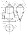
figure 1 représente le dispositif en coupe en vue de face de l'invention. - La
figure 2 représente le dispositif en coupe FF en vue de profil de l'invention. - La
figure 3 représente le dispositif en vue de dessus. - La
figure 4 représente une vue éclatée du dispositif (pièces (A), (B), (C), (D)). - La
figure 5 représente une vue éclatée du dispositif en 3 dimensions. - La
figure 6 représente une vue éclatée du dispositif (pièces (A'), (B), (C'), (D)) dans un premier mode particulier de réalisation de l'invention. - La
figure 6 bis représente une vue de face en coupe du dispositif (pièces (A'), (B), (C')) dans un premier mode particulier de réalisation de l'invention. - La
figure 7 représente une vue éclatée du dispositif en 3 dimensions, dans un premier mode particulier de réalisation de l'invention. - La
figure 8 représente une vue éclatée du dispositif (pièces (B), (C'), (D)) dans un second mode particulier de réalisation de l'invention. - La
figure 8 bis représente une vue de face en coupe du dispositif (pièces (B), (C')) dans un second mode particulier de réalisation de l'invention. - La
figure 9 représente une vue éclatée du dispositif en 3 dimensions, dans un second mode particulier de réalisation de l'invention. - La
figure 10 représente une vue éclatée du dispositif en 3 dimensions, dans un mode particulier de réalisation de l'invention. - La
figure 11 représente le dispositif, en coupe, en vue de profil de l'invention, dans sa position « plein de produit ». - La
figure 12 représente le dispositif, en coupe, en vue de profil de l'invention, dans sa position intermédiaire de vidage. - La
figure 13 représente le dispositif, en coupe, en vue de profil de l'invention, dans sa position vide avec la poche souple rétractée au maximum dans le tube.
- The
figure 1 represents the device in section in front view of the invention. - The
figure 2 represents the device in section FF in view of profile of the invention. - The
figure 3 represents the device in top view. - The
figure 4 is an exploded view of the device (parts (A), (B), (C), (D)). - The
figure 5 represents an exploded view of the device in 3 dimensions. - The
figure 6 represents an exploded view of the device (parts (A '), (B), (C'), (D)) in a first particular embodiment of the invention. - The
figure 6 bis represents a front view in section of the device (parts (A '), (B), (C')) in a first particular embodiment of the invention. - The
figure 7 represents an exploded view of the device in 3 dimensions, in a first particular embodiment of the invention. - The
figure 8 represents an exploded view of the device (parts (B), (C '), (D)) in a second particular embodiment of the invention. - The
figure 8 bis represents a front view in section of the device (parts (B), (C ')) in a second particular embodiment of the invention. - The
figure 9 represents an exploded view of the device in 3 dimensions, in a second particular embodiment of the invention. - The
figure 10 represents an exploded view of the device in 3 dimensions, in a particular embodiment of the invention. - The
figure 11 represents the device, in section, in profile view of the invention, in its "full product" position. - The
figure 12 represents the device, in section, in profile view of the invention, in its intermediate emptying position. - The
figure 13 represents the device, in section, in profile view of the invention, in its empty position with the flexible bag retracted at most in the tube.
En références à ces dessins, le dispositif est un assemblage de quatre pièces ((A), (B), (C), (D));In reference to these drawings, the device is an assembly of four parts ((A), (B), (C), (D));
Pour le cas particulier d'un tube de conditionnement, il comporte un réservoir (A)
Le dispositif comporte une poche souple cylindrique en polyéthylène pièce (B) dont l'extrémité ouverte (b2) est fixée avantageusement par thermosoudage sur l'ouverture (a5) du réservoir (A). Selon la
Le dispositif comporte un corps (C) cf.
Dans un mode de réalisation préféré, les quatre éléments de l'invention sont assemblés dans l'ordre suivant : Assemblage par soudage de la poche souple (B) et du réservoir (A), puis insertion et fixation de l'ensemble (A) et (B) dans le corps (C). Enfin, le corps (C) est obstrué à son extrémité de grande ouverture (c3) par écrasement. Le capuchon (D) se fixe sur le col (a1) dépassant du corps. La forme cylindrique et tubulaire du corps (C) n'est pas limitative, cette dernière peut prendre toutes les formes géométriques du type, flacon obstrué par un fond plat à l'extrémité (c3), coque en deux pièces cf.
Pour l'utilisation du conditionnement, il convient de boucher l'orifice (c5) avec le pouce, lorsque l'on comprime le corps (C), puis on dégage le pouce de sorte que l'air puisse à nouveau entrer dans l'espace périphérique situé entre la poche (B) et le corps (C) et ainsi de suite pour assurer la pénétration progressive par retournement de la poche (B) à l'intérieur du réservoir (A). Ainsi l'invention a pour objet un dispositif de vidange intégrale de conditionnement compressible de produits liquides, visqueux et pâteux. L'invention concerne un conditionnement permettant la vidange intégrale de récipients compressibles par pression des doigts sur leur corps. Il est constitué de quatre parties: d'un corps (C) présentant un orifice de mise à l'air libre, d'un réservoir (A) présentant un orifice d'expulsion et d'une poche souple (B) et d'un capuchon (D).To use the packaging, it is advisable to close the hole (c5) with your thumb, when you compress the body (C), then release the thumb so that the air can enter again peripheral space located between the pocket (B) and the body (C) and so on to ensure the progressive penetration by turning the bag (B) inside the tank (A). Thus, the subject of the invention is a device for integral emptying of compressible packaging of liquid, viscous and pasty products. The invention relates to a packaging for the complete emptying of compressible containers by finger pressure on their body. It consists of four parts: a body (C) having a vent hole, a tank (A) having an expulsion port and a flexible bag (B) and a a cap (D).
La poche souple se rétracte et se retourne totalement, jusqu'à se plaquer contre la paroi intérieure du réservoir. Lorsque l'utilisateur exerce plusieurs pressions sur le corps (C) du conditionnement en obstruant avec un doigt l'orifice de mise à l'air libre (c5), tout le produit contenu dans la poche souple est expulsé, progressivement et sans effort, par compression de l'air contenu dans le corps.The flexible bag retracts and turns completely, until it is pressed against the inside wall of the tank. When the user exerts several pressures on the body (C) of the packaging by obstructing with a finger the vent hole (c5), all the product contained in the flexible bag is expelled gradually and effortlessly, by compressing the air contained in the body.
Le dispositif selon l'invention s'adapte sur tous les conditionnements compressibles de produits liquides, visqueux ou pâteuxThe device according to the invention is suitable for all compressible packages of liquid, viscous or pasty products
Claims (11)
- A device composing a packaging for viscous products with complete emptying by manual pumping, comprising:- a so-called reservoir part (A) provided with one end having a tapered shoulder (a3) topped with a neck (a1), comprising a distributing channel (a2), and at the other end (a5) thereof with an orifice,- a so-called retractable flexible bag part (B) having one closed end (b1) and another open end (b2), parts (A) and (B) being welded at their respective open ends (a5) and (b2), the arrangement of the reservoir part (A) and the bag part (B) thereby composing a sealed packaging designed to receive the product, which is filled in via the distributing channel (a2) of the reservoir (A),- a so-called body part (C), provided with a lateral venting orifice (c5) manually closable so as to compose, when pressure is applied to the arrangement, a pumping system, one end (c3) of which is blocked, and the other end of which has a tapered shoulder (c4) comprising an opening (c1), with the arrangement of the reservoir (A) and bag (B) parts sealingly fitting into the body (C) in abutment against the tapered shoulder (c4) connection,- a so-called cap part (D) designed to close the neck (a1) of the assembly of the reservoir A, bag B and body C parts, characterized in that the closed end (b1) of the bag (B) is conically shaped, having an angle (αb) equal to the angle (αa) of the tapered shoulder (a3) of the reservoir (A) in order to ensure complete restitution of the product.
- The device composing a packaging for pasty products with complete emptying by manual pumping, according to claim 1, characterized in that:- the so-called reservoir part (A') is open at both ends, and at the end (a'5), the retractable flexible bag (B) is welded by the end (b2) thereof,- the so-called body part (C') is composed of a tubular skirt (c'2), one end (c'3) of which is blocked by flattening, and the other end of which has a tapered shoulder (c'4) with a neck fitted with a screw thread, comprising a distributing channel (c'6) blocked by the cap (D), and in that before blocking of the end (c'3), the arrangement of parts (A') and (B) sealingly is fitted into the body (C') in abutment against the tapered shoulder connection (c'4) by gluing.
- The device composing a packaging for pasty products with complete emptying by manual pumping according to claim 2, characterized in that the retractable flexible bag (B) has an open end (b2) directly welded over several millimeters (Las) inside the inner wall of the body (C'), such as for instance: La = Lap < Lc'/2, in that the venting orifice (c'5) is located on the body (C'), such as for instance: Lo < Lc'/2, and in that the cap (D) is blocking the neck (c'1).
- The device according to claims 1, 2, or 3, characterized in that the orifice (c5) (c'5) of the body (C), (C') is highlighted by a signaling means and positioned at a distance (Lo) from the bottom (c3) at a maximum equal to the length of the thumb, so that the thumb will naturally bear on this orifice.
- The device according to claims 1, 2, or 3, characterized in that the necks (a1) and (c'1) of parts (A) and (C') are conically or cylindrically shaped, and include the cap fastening system by screw or snap connection.
- The device according to claim 1, characterized in that assembling of the reservoir (A) with the body (C) is ensured by a screw connection with the neck (a1) going through the orifice (c1) provided with an internal thread.
- The device according to claim 1, characterized in that sealingly assembling parts (A) and (C) is done via a system for snapping the neck (a1) of the reservoir (A) through the orifice (c1) of the body (C).
- The device according to claim 1, characterized in that assembling of the reservoir (A) with the body (C) can be done, after the neck (a1) of the reservoir (A) has gone through the orifice (c1) of the body (C), by adjusting a nut or a washer, which will respectively be screwed or snapped onto the neck (a1) and thus clamp both parts together.
- The device according to claim 1 or 3, characterized in that the body (C) is composed of at least two parts thus forming the body of the compressible packaging around the assembly of the reservoir (A) and the bag (B), such as two shells or a bottle having a joined-on separate flat bottom, or else such as the head (c'1) and shoulder (c'4) arrangement, which is separate and assembled on the skirt (c'2).
- The device according to claim 1, characterized in that the cap (D) is provided with a spout orifice for product outflow, and is fastened by snap or screw connection onto the neck (a1) so as to fit parts (A) and (C) against each other.
- The device according to claims 1, 2, or 3, characterized in that the reservoir (A) has a shape which is cylindrical, circular, conical, cubical, or any combination of these shapes, in that the flexible bag (B) is dimensionally adapted to the shape of the reservoir (A).
Applications Claiming Priority (3)
| Application Number | Priority Date | Filing Date | Title |
|---|---|---|---|
| FR0211799 | 2002-09-24 | ||
| FR0211799A FR2844773B1 (en) | 2002-09-24 | 2002-09-24 | DEVICE FORMING A PACKAGING OF VISCOUS PRODUCTS WITH COMPLETE VIDAGE THROUGH MANUAL PUMPING |
| PCT/FR2003/002797 WO2004028924A1 (en) | 2002-09-24 | 2003-09-23 | Device forming packaging for viscous products, which can be fully emptied by means of manual pumping |
Publications (2)
| Publication Number | Publication Date |
|---|---|
| EP1549567A1 EP1549567A1 (en) | 2005-07-06 |
| EP1549567B1 true EP1549567B1 (en) | 2010-05-12 |
Family
ID=31970941
Family Applications (1)
| Application Number | Title | Priority Date | Filing Date |
|---|---|---|---|
| EP03798217A Expired - Lifetime EP1549567B1 (en) | 2002-09-24 | 2003-09-23 | Device forming packaging for viscous products, which can be fully emptied by means of manual pumping |
Country Status (12)
| Country | Link |
|---|---|
| US (1) | US7641078B2 (en) |
| EP (1) | EP1549567B1 (en) |
| JP (1) | JP2006500295A (en) |
| CN (1) | CN100494009C (en) |
| AT (1) | ATE467578T1 (en) |
| AU (1) | AU2003276365A1 (en) |
| CA (1) | CA2499894C (en) |
| DE (1) | DE60332546D1 (en) |
| ES (1) | ES2346054T3 (en) |
| FR (1) | FR2844773B1 (en) |
| PT (1) | PT1549567E (en) |
| WO (1) | WO2004028924A1 (en) |
Families Citing this family (24)
| Publication number | Priority date | Publication date | Assignee | Title |
|---|---|---|---|---|
| JP2006062700A (en) * | 2004-08-26 | 2006-03-09 | Katsutoshi Masuda | Fluid storage container |
| US20090188940A1 (en) * | 2007-11-24 | 2009-07-30 | Mahmoud Razzaghi | Toothpaste Tube and Dispenser |
| DE102008001204A1 (en) * | 2008-04-16 | 2009-10-22 | Robert Bosch Gmbh | Disposable filling |
| US7984831B2 (en) * | 2008-10-23 | 2011-07-26 | Gojo Industries, Inc. | Handheld dispensers for personal use |
| WO2010102044A2 (en) * | 2009-03-03 | 2010-09-10 | Gidi Shani | Volume adjusted preservation containment system |
| FR2973783B1 (en) | 2011-04-05 | 2013-05-17 | Pumpart System | VISCOUS PRODUCT PACKAGING DEVICE AND METHOD FOR IMPLEMENTING THE SAME |
| FR2973785B1 (en) | 2011-04-07 | 2014-07-18 | Valois Sas | FLUID PRODUCT DISPENSER AND METHOD FOR MANUFACTURING SUCH A DISPENSER. |
| US8960502B2 (en) * | 2011-06-08 | 2015-02-24 | Charles J Stehli, Jr. | Fluid dispenser, system and filling process |
| US9815597B2 (en) | 2013-05-20 | 2017-11-14 | Jezekiel Ben-Arie | Twist based dispenser |
| DE102013211423A1 (en) * | 2013-06-18 | 2014-12-31 | Aptar Radolfzell Gmbh | Multilayer container |
| EP2832658A1 (en) | 2013-07-30 | 2015-02-04 | ainia | Dispensing container and method of filling the container |
| CN103496513A (en) * | 2013-10-09 | 2014-01-08 | 上海和辉光电有限公司 | Photoresist inner bag |
| FR3016815B1 (en) * | 2014-01-30 | 2018-03-09 | Lablabo | DEVICE FOR PACKAGING AND DISPENSING PASTY PRODUCTS |
| FR3031089B1 (en) * | 2014-12-31 | 2017-08-18 | Karine Courtin | RIGID ENVELOPE FOR COMPRESSIBLE TUBE |
| EP3181244A1 (en) * | 2015-12-18 | 2017-06-21 | HILTI Aktiengesellschaft | Assembly consisting of a film package and a pressing device and film package |
| FR3048914B1 (en) | 2016-03-21 | 2018-09-14 | Aptar France Sas | PROCESS FOR MANUFACTURING A CONTAINER COMPRISING A FLEXIBLE POUCH AND A RIGID SHELL |
| US10118466B1 (en) | 2017-01-20 | 2018-11-06 | Meri Horn | Scented pasty wax delivery system and method and composition |
| US10040080B1 (en) * | 2017-06-21 | 2018-08-07 | Michelle Duchnowski | Tubular holder |
| JP6922523B2 (en) * | 2017-07-28 | 2021-08-18 | コクヨ株式会社 | Applied product |
| DE102018117731A1 (en) * | 2018-01-16 | 2019-07-18 | F+K Innovationen Gmbh & Co. Kg | Device for dosing liquid |
| MX2020011338A (en) * | 2018-04-27 | 2021-01-15 | Joel SHALOWITZ | Food container and dispenser. |
| US20230014631A1 (en) * | 2019-12-17 | 2023-01-19 | Edlyn Foods Pty Ltd. | A dispenser |
| EP4082936B1 (en) * | 2021-04-30 | 2023-10-18 | Jule Lucia Venrath | Container for a preferably viscous fluid |
| CN113455801B (en) * | 2021-07-20 | 2023-08-29 | 广东圣威玻璃科技有限公司 | Cosmetic packaging bottle convenient to absorb and thoroughly clean to use |
Family Cites Families (15)
| Publication number | Priority date | Publication date | Assignee | Title |
|---|---|---|---|---|
| US2671579A (en) * | 1948-08-30 | 1954-03-09 | Fyr Fyter Co | Collapsible tube and protective jacket therefor |
| US2777612A (en) * | 1951-05-15 | 1957-01-15 | Richard E Bensen | Compression type dispensing device |
| US3306500A (en) * | 1965-11-12 | 1967-02-28 | Alfred D Williams | Squeeze tube dispenser |
| US4020978A (en) * | 1975-08-15 | 1977-05-03 | Harry Szczepanski | Manually-operated dispenser |
| US4842165A (en) * | 1987-08-28 | 1989-06-27 | The Procter & Gamble Company | Resilient squeeze bottle package for dispensing viscous products without belching |
| US5012956A (en) * | 1989-08-07 | 1991-05-07 | Stoody William R | Squeeze bottle with bag, dispensing system |
| DE4106919A1 (en) * | 1991-03-05 | 1992-09-10 | Kautex Werke Gmbh | CRUSH BOTTLE WITH INNER CONTAINER |
| CN2105468U (en) * | 1991-09-09 | 1992-05-27 | 余宁伊 | Plastic toothpaste tube |
| JPH0554345U (en) * | 1991-12-20 | 1993-07-20 | サンスター株式会社 | Viscous liquid dispensing container |
| CA2127547A1 (en) * | 1992-01-13 | 1993-07-22 | David Seidler | Squeeze bottle package |
| DE4332885A1 (en) * | 1992-09-28 | 1994-03-31 | Colgate Palmolive Co | Squeezable dispenser for toothpaste etc. - has inner flexible disposable container fitting into outer container and closed by cap and one-way locking valves |
| US5373967A (en) * | 1993-12-07 | 1994-12-20 | The Procter & Gamble Company | Squeezebottle dispenser having a channeled vent valve |
| US5429702A (en) * | 1994-07-07 | 1995-07-04 | The Procter & Gamble Company | Method for sealing an inner bag to an outer container |
| FR2775957B1 (en) | 1998-03-16 | 2000-06-30 | Joseph Eugene Stervinou | DEVICE FOR FACILITATING THE USE OF FLEXIBLE MATERIAL TUBES |
| FR2796622B1 (en) | 1999-07-23 | 2001-12-14 | Oreal | PACKAGING OF PASTA LIQUID PRODUCT WITH IMPROVED DRAIN RATE |
-
2002
- 2002-09-24 FR FR0211799A patent/FR2844773B1/en not_active Expired - Fee Related
-
2003
- 2003-09-23 AT AT03798217T patent/ATE467578T1/en active
- 2003-09-23 PT PT03798217T patent/PT1549567E/en unknown
- 2003-09-23 WO PCT/FR2003/002797 patent/WO2004028924A1/en active Application Filing
- 2003-09-23 JP JP2004539129A patent/JP2006500295A/en active Pending
- 2003-09-23 CA CA2499894A patent/CA2499894C/en not_active Expired - Fee Related
- 2003-09-23 ES ES03798217T patent/ES2346054T3/en not_active Expired - Lifetime
- 2003-09-23 DE DE60332546T patent/DE60332546D1/en not_active Expired - Lifetime
- 2003-09-23 EP EP03798217A patent/EP1549567B1/en not_active Expired - Lifetime
- 2003-09-23 CN CNB038228270A patent/CN100494009C/en not_active Expired - Fee Related
- 2003-09-23 AU AU2003276365A patent/AU2003276365A1/en not_active Abandoned
- 2003-09-23 US US10/529,179 patent/US7641078B2/en not_active Expired - Fee Related
Also Published As
| Publication number | Publication date |
|---|---|
| EP1549567A1 (en) | 2005-07-06 |
| CN100494009C (en) | 2009-06-03 |
| CA2499894C (en) | 2011-05-31 |
| WO2004028924A1 (en) | 2004-04-08 |
| PT1549567E (en) | 2010-08-18 |
| US7641078B2 (en) | 2010-01-05 |
| CA2499894A1 (en) | 2004-04-08 |
| FR2844773A1 (en) | 2004-03-26 |
| US20060163287A1 (en) | 2006-07-27 |
| JP2006500295A (en) | 2006-01-05 |
| FR2844773B1 (en) | 2005-01-28 |
| AU2003276365A1 (en) | 2004-04-19 |
| DE60332546D1 (en) | 2010-06-24 |
| ES2346054T3 (en) | 2010-10-08 |
| ATE467578T1 (en) | 2010-05-15 |
| CN1684880A (en) | 2005-10-19 |
Similar Documents
| Publication | Publication Date | Title |
|---|---|---|
| EP1549567B1 (en) | Device forming packaging for viscous products, which can be fully emptied by means of manual pumping | |
| CA2055690C (en) | Dispenser for liquid to pasty products and holder for such dispenser | |
| FR2666305A1 (en) | DEVICE FOR STORING SEPARATELY FROM AT LEAST TWO PRODUCTS AND FOR MAKING THEIR MIXTURE AT THE TIME OF USE. | |
| EP0582517B1 (en) | Dispenser for fluids and its manufacturing method | |
| EP1606190B1 (en) | Closure device for a fluid product reservoir | |
| WO1990008074A1 (en) | Liquid-tight closure assembly with multidirectional orientation and retractible pourer tube | |
| WO1992004252A1 (en) | Tamper-proof packaging having inner and outer wrappings and method for producing same | |
| EP0786419B1 (en) | Dosing bottle | |
| EP3999245A1 (en) | Device for capping a container of a liquid to pasty product, and refill closed by such a device | |
| EP0406134A1 (en) | Container with elastic bottle | |
| EP0755872B1 (en) | Container provided with a distributing opening and a closure device | |
| WO2006090061A1 (en) | Creamy product dispensing tube | |
| CA2314827C (en) | Packaging offering improved emptying for a pasty liquid product | |
| EP0559881B1 (en) | Method for angularly positioning an adjustable sealing device relative to a flexible dispensing tube comprising indicia | |
| FR2952357A1 (en) | FLUID CONTAINER COMPRISING A POCKET INTENDED TO CONTAIN SUCH FLUID, AND IS ASSOCIATED | |
| EP1284905B1 (en) | Packaging for fluid product with hinge closure | |
| FR2671538A1 (en) | Device for dispensing and metering products | |
| WO2003051270A2 (en) | Administration tip for a flexible bag for medical use | |
| WO2003070597A1 (en) | Fluid product dispenser | |
| CA2297765C (en) | Valve for pressurised fluid device | |
| WO1998028204A2 (en) | Container for packaging two products to be poured and kept separately before being mixed for use | |
| FR2826245A1 (en) | Fluid cosmetic sample dispenser comprises container with ring engaging internal surface forming stop for piston and dispensing head having outlet channel | |
| FR2801040A1 (en) | Dispenser for viscous liquids has screw action casing which twists internal bag to dispense contents | |
| CH662796A5 (en) | CONTAINER FOR DRIPPING A DOSE OF FLUID SUBSTANCE. | |
| BE482700A (en) |
Legal Events
| Date | Code | Title | Description |
|---|---|---|---|
| PUAI | Public reference made under article 153(3) epc to a published international application that has entered the european phase |
Free format text: ORIGINAL CODE: 0009012 |
|
| 17P | Request for examination filed |
Effective date: 20050415 |
|
| AK | Designated contracting states |
Kind code of ref document: A1 Designated state(s): AT BE BG CH CY CZ DE DK EE ES FI FR GB GR HU IE IT LI LU MC NL PT RO SE SI SK TR |
|
| AX | Request for extension of the european patent |
Extension state: AL LT LV MK |
|
| DAX | Request for extension of the european patent (deleted) | ||
| 17Q | First examination report despatched |
Effective date: 20081217 |
|
| R17C | First examination report despatched (corrected) |
Effective date: 20090109 |
|
| GRAP | Despatch of communication of intention to grant a patent |
Free format text: ORIGINAL CODE: EPIDOSNIGR1 |
|
| GRAS | Grant fee paid |
Free format text: ORIGINAL CODE: EPIDOSNIGR3 |
|
| GRAA | (expected) grant |
Free format text: ORIGINAL CODE: 0009210 |
|
| AK | Designated contracting states |
Kind code of ref document: B1 Designated state(s): AT BE BG CH CY CZ DE DK EE ES FI FR GB GR HU IE IT LI LU MC NL PT RO SE SI SK TR |
|
| REG | Reference to a national code |
Ref country code: GB Ref legal event code: FG4D Free format text: NOT ENGLISH |
|
| REG | Reference to a national code |
Ref country code: CH Ref legal event code: EP |
|
| BECA | Be: change of holder's address |
Owner name: PUMPART SYSTEM S.A.S.5 RUE MARCEL ALLEGOT, F-92190 Effective date: 20100512 |
|
| BECH | Be: change of holder |
Owner name: PUMPART SYSTEM S.A.S. Effective date: 20100512 |
|
| REG | Reference to a national code |
Ref country code: IE Ref legal event code: FG4D Free format text: LANGUAGE OF EP DOCUMENT: FRENCH |
|
| REF | Corresponds to: |
Ref document number: 60332546 Country of ref document: DE Date of ref document: 20100624 Kind code of ref document: P |
|
| RAP2 | Party data changed (patent owner data changed or rights of a patent transferred) |
Owner name: PUMPART SYSTEM S.A.S. |
|
| RIN2 | Information on inventor provided after grant (corrected) |
Inventor name: BOUMNSO, JEROME |
|
| REG | Reference to a national code |
Ref country code: RO Ref legal event code: EPE |
|
| REG | Reference to a national code |
Ref country code: PT Ref legal event code: SC4A Free format text: AVAILABILITY OF NATIONAL TRANSLATION Effective date: 20100809 |
|
| REG | Reference to a national code |
Ref country code: NL Ref legal event code: T3 |
|
| REG | Reference to a national code |
Ref country code: GR Ref legal event code: EP Ref document number: 20100401915 Country of ref document: GR |
|
| REG | Reference to a national code |
Ref country code: ES Ref legal event code: FG2A Ref document number: 2346054 Country of ref document: ES Kind code of ref document: T3 |
|
| PG25 | Lapsed in a contracting state [announced via postgrant information from national office to epo] |
Ref country code: SE Free format text: LAPSE BECAUSE OF FAILURE TO SUBMIT A TRANSLATION OF THE DESCRIPTION OR TO PAY THE FEE WITHIN THE PRESCRIBED TIME-LIMIT Effective date: 20100512 |
|
| PG25 | Lapsed in a contracting state [announced via postgrant information from national office to epo] |
Ref country code: FI Free format text: LAPSE BECAUSE OF FAILURE TO SUBMIT A TRANSLATION OF THE DESCRIPTION OR TO PAY THE FEE WITHIN THE PRESCRIBED TIME-LIMIT Effective date: 20100512 Ref country code: SI Free format text: LAPSE BECAUSE OF FAILURE TO SUBMIT A TRANSLATION OF THE DESCRIPTION OR TO PAY THE FEE WITHIN THE PRESCRIBED TIME-LIMIT Effective date: 20100512 |
|
| REG | Reference to a national code |
Ref country code: IE Ref legal event code: FD4D |
|
| PG25 | Lapsed in a contracting state [announced via postgrant information from national office to epo] |
Ref country code: CY Free format text: LAPSE BECAUSE OF FAILURE TO SUBMIT A TRANSLATION OF THE DESCRIPTION OR TO PAY THE FEE WITHIN THE PRESCRIBED TIME-LIMIT Effective date: 20100512 |
|
| PG25 | Lapsed in a contracting state [announced via postgrant information from national office to epo] |
Ref country code: DK Free format text: LAPSE BECAUSE OF FAILURE TO SUBMIT A TRANSLATION OF THE DESCRIPTION OR TO PAY THE FEE WITHIN THE PRESCRIBED TIME-LIMIT Effective date: 20100512 Ref country code: IE Free format text: LAPSE BECAUSE OF FAILURE TO SUBMIT A TRANSLATION OF THE DESCRIPTION OR TO PAY THE FEE WITHIN THE PRESCRIBED TIME-LIMIT Effective date: 20100512 Ref country code: EE Free format text: LAPSE BECAUSE OF FAILURE TO SUBMIT A TRANSLATION OF THE DESCRIPTION OR TO PAY THE FEE WITHIN THE PRESCRIBED TIME-LIMIT Effective date: 20100512 |
|
| REG | Reference to a national code |
Ref country code: PT Ref legal event code: PC4A Owner name: PUMPART SYSTEM S.A.S, FR Effective date: 20110120 |
|
| REG | Reference to a national code |
Ref country code: NL Ref legal event code: SD Effective date: 20110127 |
|
| PG25 | Lapsed in a contracting state [announced via postgrant information from national office to epo] |
Ref country code: SK Free format text: LAPSE BECAUSE OF FAILURE TO SUBMIT A TRANSLATION OF THE DESCRIPTION OR TO PAY THE FEE WITHIN THE PRESCRIBED TIME-LIMIT Effective date: 20100512 Ref country code: CZ Free format text: LAPSE BECAUSE OF FAILURE TO SUBMIT A TRANSLATION OF THE DESCRIPTION OR TO PAY THE FEE WITHIN THE PRESCRIBED TIME-LIMIT Effective date: 20100512 |
|
| REG | Reference to a national code |
Ref country code: GB Ref legal event code: 732E Free format text: REGISTERED BETWEEN 20110203 AND 20110209 |
|
| PLBE | No opposition filed within time limit |
Free format text: ORIGINAL CODE: 0009261 |
|
| STAA | Information on the status of an ep patent application or granted ep patent |
Free format text: STATUS: NO OPPOSITION FILED WITHIN TIME LIMIT |
|
| 26N | No opposition filed |
Effective date: 20110215 |
|
| REG | Reference to a national code |
Ref country code: DE Ref legal event code: R081 Ref document number: 60332546 Country of ref document: DE Owner name: PUMPART SYSTEM S.A.S., FR Free format text: FORMER OWNER: BOUMSO, JEROME, CHATILLON, FR Effective date: 20110302 |
|
| REG | Reference to a national code |
Ref country code: DE Ref legal event code: R097 Ref document number: 60332546 Country of ref document: DE Effective date: 20110214 |
|
| PG25 | Lapsed in a contracting state [announced via postgrant information from national office to epo] |
Ref country code: HU Free format text: LAPSE BECAUSE OF FAILURE TO SUBMIT A TRANSLATION OF THE DESCRIPTION OR TO PAY THE FEE WITHIN THE PRESCRIBED TIME-LIMIT Effective date: 20101113 Ref country code: BG Free format text: LAPSE BECAUSE OF FAILURE TO SUBMIT A TRANSLATION OF THE DESCRIPTION OR TO PAY THE FEE WITHIN THE PRESCRIBED TIME-LIMIT Effective date: 20100512 |
|
| PG25 | Lapsed in a contracting state [announced via postgrant information from national office to epo] |
Ref country code: BG Free format text: LAPSE BECAUSE OF FAILURE TO SUBMIT A TRANSLATION OF THE DESCRIPTION OR TO PAY THE FEE WITHIN THE PRESCRIBED TIME-LIMIT Effective date: 20100812 |
|
| PGFP | Annual fee paid to national office [announced via postgrant information from national office to epo] |
Ref country code: RO Payment date: 20130826 Year of fee payment: 11 Ref country code: PT Payment date: 20130325 Year of fee payment: 11 Ref country code: NL Payment date: 20130918 Year of fee payment: 11 Ref country code: AT Payment date: 20130911 Year of fee payment: 11 Ref country code: MC Payment date: 20130911 Year of fee payment: 11 Ref country code: GR Payment date: 20130918 Year of fee payment: 11 |
|
| PGFP | Annual fee paid to national office [announced via postgrant information from national office to epo] |
Ref country code: TR Payment date: 20130823 Year of fee payment: 11 |
|
| PGFP | Annual fee paid to national office [announced via postgrant information from national office to epo] |
Ref country code: LU Payment date: 20131002 Year of fee payment: 11 |
|
| REG | Reference to a national code |
Ref country code: PT Ref legal event code: MM4A Free format text: LAPSE DUE TO NON-PAYMENT OF FEES Effective date: 20150323 |
|
| PG25 | Lapsed in a contracting state [announced via postgrant information from national office to epo] |
Ref country code: LU Free format text: LAPSE BECAUSE OF NON-PAYMENT OF DUE FEES Effective date: 20140923 Ref country code: PT Free format text: LAPSE BECAUSE OF NON-PAYMENT OF DUE FEES Effective date: 20150323 Ref country code: RO Free format text: LAPSE BECAUSE OF NON-PAYMENT OF DUE FEES Effective date: 20140923 Ref country code: MC Free format text: LAPSE BECAUSE OF NON-PAYMENT OF DUE FEES Effective date: 20140930 |
|
| REG | Reference to a national code |
Ref country code: AT Ref legal event code: MM01 Ref document number: 467578 Country of ref document: AT Kind code of ref document: T Effective date: 20140923 |
|
| REG | Reference to a national code |
Ref country code: GR Ref legal event code: ML Ref document number: 20100401915 Country of ref document: GR Effective date: 20150403 |
|
| PG25 | Lapsed in a contracting state [announced via postgrant information from national office to epo] |
Ref country code: NL Free format text: LAPSE BECAUSE OF NON-PAYMENT OF DUE FEES Effective date: 20150401 |
|
| PG25 | Lapsed in a contracting state [announced via postgrant information from national office to epo] |
Ref country code: AT Free format text: LAPSE BECAUSE OF NON-PAYMENT OF DUE FEES Effective date: 20140923 Ref country code: GR Free format text: LAPSE BECAUSE OF NON-PAYMENT OF DUE FEES Effective date: 20150403 |
|
| REG | Reference to a national code |
Ref country code: FR Ref legal event code: PLFP Year of fee payment: 14 |
|
| PG25 | Lapsed in a contracting state [announced via postgrant information from national office to epo] |
Ref country code: TR Free format text: LAPSE BECAUSE OF NON-PAYMENT OF DUE FEES Effective date: 20140923 |
|
| REG | Reference to a national code |
Ref country code: FR Ref legal event code: PLFP Year of fee payment: 15 |
|
| REG | Reference to a national code |
Ref country code: FR Ref legal event code: PLFP Year of fee payment: 16 |
|
| PGFP | Annual fee paid to national office [announced via postgrant information from national office to epo] |
Ref country code: CH Payment date: 20201021 Year of fee payment: 18 |
|
| PGFP | Annual fee paid to national office [announced via postgrant information from national office to epo] |
Ref country code: BE Payment date: 20210331 Year of fee payment: 18 |
|
| PGFP | Annual fee paid to national office [announced via postgrant information from national office to epo] |
Ref country code: GB Payment date: 20220331 Year of fee payment: 19 Ref country code: DE Payment date: 20220331 Year of fee payment: 19 |
|
| REG | Reference to a national code |
Ref country code: CH Ref legal event code: PL |
|
| REG | Reference to a national code |
Ref country code: BE Ref legal event code: MM Effective date: 20210930 |
|
| PG25 | Lapsed in a contracting state [announced via postgrant information from national office to epo] |
Ref country code: BE Free format text: LAPSE BECAUSE OF NON-PAYMENT OF DUE FEES Effective date: 20210930 |
|
| PGFP | Annual fee paid to national office [announced via postgrant information from national office to epo] |
Ref country code: IT Payment date: 20220331 Year of fee payment: 19 Ref country code: ES Payment date: 20220426 Year of fee payment: 19 |
|
| PG25 | Lapsed in a contracting state [announced via postgrant information from national office to epo] |
Ref country code: LI Free format text: LAPSE BECAUSE OF NON-PAYMENT OF DUE FEES Effective date: 20210930 Ref country code: CH Free format text: LAPSE BECAUSE OF NON-PAYMENT OF DUE FEES Effective date: 20210930 |
|
| PGFP | Annual fee paid to national office [announced via postgrant information from national office to epo] |
Ref country code: FR Payment date: 20220922 Year of fee payment: 20 |
|
| REG | Reference to a national code |
Ref country code: DE Ref legal event code: R119 Ref document number: 60332546 Country of ref document: DE |
|
| GBPC | Gb: european patent ceased through non-payment of renewal fee |
Effective date: 20220923 |
|
| PG25 | Lapsed in a contracting state [announced via postgrant information from national office to epo] |
Ref country code: DE Free format text: LAPSE BECAUSE OF NON-PAYMENT OF DUE FEES Effective date: 20230401 |
|
| REG | Reference to a national code |
Ref country code: ES Ref legal event code: FD2A Effective date: 20231027 |
|
| PG25 | Lapsed in a contracting state [announced via postgrant information from national office to epo] |
Ref country code: IT Free format text: LAPSE BECAUSE OF NON-PAYMENT OF DUE FEES Effective date: 20220923 Ref country code: GB Free format text: LAPSE BECAUSE OF NON-PAYMENT OF DUE FEES Effective date: 20220923 |
|
| PG25 | Lapsed in a contracting state [announced via postgrant information from national office to epo] |
Ref country code: ES Free format text: LAPSE BECAUSE OF NON-PAYMENT OF DUE FEES Effective date: 20220924 |
|
| PG25 | Lapsed in a contracting state [announced via postgrant information from national office to epo] |
Ref country code: ES Free format text: LAPSE BECAUSE OF NON-PAYMENT OF DUE FEES Effective date: 20220924 |