EP3240096A1 - Système et procédé de protection de bloc-batterie - Google Patents
Système et procédé de protection de bloc-batterie Download PDFInfo
- Publication number
- EP3240096A1 EP3240096A1 EP16807652.9A EP16807652A EP3240096A1 EP 3240096 A1 EP3240096 A1 EP 3240096A1 EP 16807652 A EP16807652 A EP 16807652A EP 3240096 A1 EP3240096 A1 EP 3240096A1
- Authority
- EP
- European Patent Office
- Prior art keywords
- gradient
- value
- algorithm
- battery
- measurement value
- Prior art date
- Legal status (The legal status is an assumption and is not a legal conclusion. Google has not performed a legal analysis and makes no representation as to the accuracy of the status listed.)
- Withdrawn
Links
Images


Classifications
-
- H—ELECTRICITY
- H02—GENERATION; CONVERSION OR DISTRIBUTION OF ELECTRIC POWER
- H02H—EMERGENCY PROTECTIVE CIRCUIT ARRANGEMENTS
- H02H7/00—Emergency protective circuit arrangements specially adapted for specific types of electric machines or apparatus or for sectionalised protection of cable or line systems, and effecting automatic switching in the event of an undesired change from normal working conditions
- H02H7/18—Emergency protective circuit arrangements specially adapted for specific types of electric machines or apparatus or for sectionalised protection of cable or line systems, and effecting automatic switching in the event of an undesired change from normal working conditions for batteries; for accumulators
-
- H—ELECTRICITY
- H01—ELECTRIC ELEMENTS
- H01M—PROCESSES OR MEANS, e.g. BATTERIES, FOR THE DIRECT CONVERSION OF CHEMICAL ENERGY INTO ELECTRICAL ENERGY
- H01M10/00—Secondary cells; Manufacture thereof
- H01M10/42—Methods or arrangements for servicing or maintenance of secondary cells or secondary half-cells
- H01M10/425—Structural combination with electronic components, e.g. electronic circuits integrated to the outside of the casing
-
- H—ELECTRICITY
- H01—ELECTRIC ELEMENTS
- H01M—PROCESSES OR MEANS, e.g. BATTERIES, FOR THE DIRECT CONVERSION OF CHEMICAL ENERGY INTO ELECTRICAL ENERGY
- H01M10/00—Secondary cells; Manufacture thereof
- H01M10/42—Methods or arrangements for servicing or maintenance of secondary cells or secondary half-cells
- H01M10/48—Accumulators combined with arrangements for measuring, testing or indicating the condition of cells, e.g. the level or density of the electrolyte
- H01M10/482—Accumulators combined with arrangements for measuring, testing or indicating the condition of cells, e.g. the level or density of the electrolyte for several batteries or cells simultaneously or sequentially
-
- H—ELECTRICITY
- H01—ELECTRIC ELEMENTS
- H01M—PROCESSES OR MEANS, e.g. BATTERIES, FOR THE DIRECT CONVERSION OF CHEMICAL ENERGY INTO ELECTRICAL ENERGY
- H01M10/00—Secondary cells; Manufacture thereof
- H01M10/42—Methods or arrangements for servicing or maintenance of secondary cells or secondary half-cells
- H01M10/4207—Methods or arrangements for servicing or maintenance of secondary cells or secondary half-cells for several batteries or cells simultaneously or sequentially
-
- H—ELECTRICITY
- H01—ELECTRIC ELEMENTS
- H01M—PROCESSES OR MEANS, e.g. BATTERIES, FOR THE DIRECT CONVERSION OF CHEMICAL ENERGY INTO ELECTRICAL ENERGY
- H01M10/00—Secondary cells; Manufacture thereof
- H01M10/42—Methods or arrangements for servicing or maintenance of secondary cells or secondary half-cells
- H01M10/4228—Leak testing of cells or batteries
-
- H—ELECTRICITY
- H01—ELECTRIC ELEMENTS
- H01M—PROCESSES OR MEANS, e.g. BATTERIES, FOR THE DIRECT CONVERSION OF CHEMICAL ENERGY INTO ELECTRICAL ENERGY
- H01M10/00—Secondary cells; Manufacture thereof
- H01M10/42—Methods or arrangements for servicing or maintenance of secondary cells or secondary half-cells
- H01M10/48—Accumulators combined with arrangements for measuring, testing or indicating the condition of cells, e.g. the level or density of the electrolyte
-
- H—ELECTRICITY
- H01—ELECTRIC ELEMENTS
- H01M—PROCESSES OR MEANS, e.g. BATTERIES, FOR THE DIRECT CONVERSION OF CHEMICAL ENERGY INTO ELECTRICAL ENERGY
- H01M50/00—Constructional details or processes of manufacture of the non-active parts of electrochemical cells other than fuel cells, e.g. hybrid cells
- H01M50/50—Current conducting connections for cells or batteries
- H01M50/572—Means for preventing undesired use or discharge
- H01M50/574—Devices or arrangements for the interruption of current
-
- H—ELECTRICITY
- H01—ELECTRIC ELEMENTS
- H01M—PROCESSES OR MEANS, e.g. BATTERIES, FOR THE DIRECT CONVERSION OF CHEMICAL ENERGY INTO ELECTRICAL ENERGY
- H01M10/00—Secondary cells; Manufacture thereof
- H01M10/42—Methods or arrangements for servicing or maintenance of secondary cells or secondary half-cells
- H01M10/425—Structural combination with electronic components, e.g. electronic circuits integrated to the outside of the casing
- H01M2010/4271—Battery management systems including electronic circuits, e.g. control of current or voltage to keep battery in healthy state, cell balancing
-
- H—ELECTRICITY
- H01—ELECTRIC ELEMENTS
- H01M—PROCESSES OR MEANS, e.g. BATTERIES, FOR THE DIRECT CONVERSION OF CHEMICAL ENERGY INTO ELECTRICAL ENERGY
- H01M2200/00—Safety devices for primary or secondary batteries
-
- H—ELECTRICITY
- H01—ELECTRIC ELEMENTS
- H01M—PROCESSES OR MEANS, e.g. BATTERIES, FOR THE DIRECT CONVERSION OF CHEMICAL ENERGY INTO ELECTRICAL ENERGY
- H01M2220/00—Batteries for particular applications
- H01M2220/20—Batteries in motive systems, e.g. vehicle, ship, plane
-
- Y—GENERAL TAGGING OF NEW TECHNOLOGICAL DEVELOPMENTS; GENERAL TAGGING OF CROSS-SECTIONAL TECHNOLOGIES SPANNING OVER SEVERAL SECTIONS OF THE IPC; TECHNICAL SUBJECTS COVERED BY FORMER USPC CROSS-REFERENCE ART COLLECTIONS [XRACs] AND DIGESTS
- Y02—TECHNOLOGIES OR APPLICATIONS FOR MITIGATION OR ADAPTATION AGAINST CLIMATE CHANGE
- Y02E—REDUCTION OF GREENHOUSE GAS [GHG] EMISSIONS, RELATED TO ENERGY GENERATION, TRANSMISSION OR DISTRIBUTION
- Y02E60/00—Enabling technologies; Technologies with a potential or indirect contribution to GHG emissions mitigation
- Y02E60/10—Energy storage using batteries
Definitions
- the present invention relates to a system and a method of protecting a battery pack, and more particularly, to a system and a method of protecting a battery pack, which measure a gradient of one or more battery packs, determine whether the measurement value exceeds a predetermined threshold gradient value, and control an operation of a switch provided on a connection path between the one or more battery packs and an external power source based on a result of the determination, thereby blocking a path of a power source supplied to a battery pack and preventing an accident, such as leakage of an electrolyte of the battery cell and an electrical short of a high voltage and a high current when the battery pack is abnormally inclined.
- a battery is called as a storage battery or a secondary cell, and means a device storing or outputting electric energy generated by a chemical reaction between an electrolyte and an electrode existing within the battery.
- the battery has a characteristic in an easy application according to a product group, excellent preservability, a high energy density, and the like. Further, the battery attracts attention as a new energy source for improving an environmentally-friendly characteristic and energy efficiency in that a by-product according to the use of energy is not generated, as well as a primary advantage in that it is possible to decrease the use of fossil fuel.
- the battery is universally applied to an electric vehicle (EV) or an energy storage system (ESS) driven by an electrical driving source, including a portable device.
- EV electric vehicle
- ESS energy storage system
- the electric vehicle is on the rise as an alternative in an era in which a pollution problem becomes serious day by day and oil price is high, and in Korea, various businesses have been pushed forward for an entrance to the four world powers in an electric vehicle field up to the year of 2020.
- the electric vehicle is propelled while driving an electric motor by using electric energy accumulated in the battery as a power source, unlike an existing vehicle, which obtains driving energy while combusting fossil fuel. That is, the battery may be considered as a core factor determining travelling of the electric vehicle, and a speed and a driving distance of the electric vehicle.
- Korean Patent Application Laid-Open No. 2010-0115513 relates to a battery saver system for a vehicle, and describes the configuration, in which a main power source is controlled by sensing a voltage of a battery, thereby protecting a battery used in a vehicle.
- the related art is configured to protect the battery from an electrical problem, such as overcharging and overdischarging, but passes over an accident incurable by a physical change of the battery.
- the internal battery may deviate from an existing fixed position and be inclined, and in this case, a high voltage and a high current may leak from the battery to cause a failure of a battery pack or cause electric shock to a human body riding inside the vehicle.
- the battery for a vehicle is inclined by physical impact by a primary accident of the vehicle, and thus, a secondary accident, such as an electrical short, leakage of electrolyte, and electric shock, may be incurred.
- the related art detects only an electrical problem of the battery, but has a problem in failing to detect a physical change of the battery.
- the present invention is conceived to solve the aforementioned problem, and an object of the present invention is to provide a system and a method of protecting a battery pack, which measure a gradient of a battery pack, determine whether the measurement value exceeds a predetermined threshold gradient value, and control an operation of a switch provided on a connection path between the battery pack and an external power source based on a result of the determination, thereby blocking a path of a power source supplied to a battery pack and preventing an accident, such as leakage of an electrolyte of the battery cell and an electrical short of a high voltage and a high current when the battery pack is abnormally inclined.
- an object of the present invention is to provide a system and a method of protecting a battery pack, which blocks a power source path to a battery pack and controls peripheral devices, such as a fan, a cooling valve, and a motor, to be operated to be off when the battery pack is inclined while exceeding a threshold gradient value, thereby preventing unnecessary driving of the peripheral devices and power consumption.
- peripheral devices such as a fan, a cooling valve, and a motor
- An exemplary embodiment of the present invention provides a system for protecting a battery pack, including: one or more battery packs including a plurality of cells; a switch unit configured to open and close a connection path between the one or more battery packs and an external power source; a detecting unit configured to measure a physical gradient of the one or more battery packs; and a control unit configured to control an operation of the switch unit based on a measurement value of the detecting unit.
- the switch unit may be formed of one or more of a field effect transistor FET and a relay.
- the detecting unit may measure the gradient of the one or more battery packs by using a gradient measuring sensor at a predetermined time interval, and transmit the measurement value to the control unit.
- the control unit may include: an algorithm, into which the measurement value received from the detecting unit is input, and from which a result value is output; and a driving driver configured to control an operation of the switch unit based on the result value of the algorithm.
- the algorithm may include a command determining whether the measurement value exceeds a predetermined threshold gradient value.
- the algorithm may output a first result value, and when the measurement value does not exceed the threshold gradient value, the algorithm may output a second result value.
- the driving driver may transmit an open operation signal to the switch unit, and when the second result value is output from the algorithm, the driving driver may transmit a close operation signal to the switch unit.
- the driving driver may control an off operation of a separate peripheral device, and the separate peripheral device may be one of an air-cooling type fan and a water-cooling type cooling valve.
- Another exemplary embodiment of the present invention provides a method of protecting a battery pack, including: measuring a physical gradient of the one or more battery packs formed of a plurality of cells; and controlling an operation of a switch provided on a connection path between the one or more battery packs and an external power source based on a measurement value of the measuring of the gradient.
- the measuring of the gradient may include measuring the gradient of the one or more battery packs by using a gradient measuring sensor at a predetermined time interval, and controlling an operation of the switch based on the measurement value.
- the controlling of the operation of the switch may include inputting the measurement value received from the measuring of the gradient to an algorithm and outputting a result value.
- the algorithm may include a command determining whether the measurement value exceeds a predetermined threshold gradient value.
- the algorithm may output a first result value, and when the measurement value does not exceed the threshold gradient value, the algorithm may output a second result value.
- the controlling of the operation of the switch may include controlling the switch to perform an open operation when the first result value is output from the algorithm, and controlling the switch to perform a close operation when the second result value is output from the algorithm.
- the system and the method for protecting a battery pack which measure a gradient of a battery pack, determine whether the measurement value exceeds a predetermined threshold gradient value, and control a switch provided on a connection path between the battery pack and an external power source to perform an open operation when the measurement value exceeds the threshold gradient value.
- ... unit described in the specification means a unit for processing at least one function and operation and may be implemented by hardware components or software components and combinations thereof.
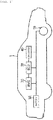
- FIG. 1 is a diagram schematically illustrating an electric vehicle, to which a system and a method of protecting a battery pack according to an exemplary embodiment of the present invention are applicable.
- system and the method of protecting the battery pack according to the exemplary embodiment of the present invention are applicable to various technical fields using a battery, in addition to an electric vehicle 1.
- the electric vehicle 1 may include a battery 10, a battery management system (BMS) 20, an electronic control unit (ECU) 30, an inverter 40, and a motor 50.
- BMS battery management system
- ECU electronice control unit
- the battery 10 is an electric energy source providing driving force to the motor 50 and driving the electric vehicle 1, and may be charged or discharged by the inverter 40 according to the driving of the motor 50 and/or an internal combustion engine (not illustrated).
- the kind of battery 10 is not particularly limited, and examples of the battery 10 may include a lithium ion battery, a lithium polymer battery, a nickel cadmium battery, a nickel hydrogen battery, and a nickel zinc battery.
- the BMS 20 may estimate a state of the battery 10 and control a charging/discharging current of the battery 10 by using information about the state, and further control an opening/closing operation of a contactor.
- the ECU 30 is an electronic control device for controlling a state of the electric vehicle 1. For example, the ECU 30 determines a torque level based on information about an accelerator, a brake, a speed, and the like, and controls an output of the motor 50 to correspond to torque information.
- the inverter 40 makes the battery 10 be charged or discharged based on a control signal of the ECU 30.
- the motor 50 drives the electric vehicle 1 based on electric energy of the battery 10 and control information transmitted from the ECU 30.
- the electric vehicle 1 is propelled while driving the motor 50 with the electric energy received from the battery 10, so that when a state of the battery 10 is abnormal, a failure and an accident of the electric vehicle 1 may be incurred.
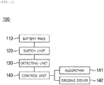
- FIG. 2 is a diagram schematically illustrating a configuration of the system for protecting the battery pack according to the exemplary embodiment of the present invention
- FIG. 3 is a diagram schematically illustrating a circuit diagram of the system for protecting the battery pack according to the exemplary embodiment of the present invention.
- the system 100 for protecting the battery pack may include a battery pack 110, a switch unit 120, a detecting unit 130, and a control unit 140.
- system 100 for protecting the battery pack illustrated in FIGS. 2 and 3 is an exemplary embodiment, and constituent elements thereof are not limited to the exemplary embodiment illustrated in FIGS. 2 and 3 , and some constituent elements may be added, changed, or removed as necessary.
- the present invention is described based on the protection of the battery pack 110 as an exemplary embodiment, but the battery pack 110 is a concept including both a battery cell and a battery module, so that it is noted that the present invention is capable of protecting a battery cell and a battery module, as well as the battery pack 110.
- the battery pack 110 includes a plurality of serially connected battery cells and battery modules, and one or more battery packs 110 are configured, and the battery pack 110 may serve to accumulate electric energy and supply the electric energy to an electric system.
- the kind of battery forming the one or more battery packs 110 is not limited.
- the one or more battery packs 110 are electrically connected with an external power source, and the switch unit 120 may be provided on a connection path.
- the switch unit 120 is installed between the one or more battery packs 110 and the external power source and is opened/closed according to the control signal of the control unit 140, which is to be described below, and the one or more battery packs 110 and the external power source may be connected or blocked by the open/close operation of the switch unit 120.
- the switch unit 120 is formed of one or more of a field effect transistor (FET) and a relay, and may be provided at an upper side and a lower side of the one or more battery packs 110.
- FET field effect transistor
- the kind of contactor configuring the switch unit 120 is not limited, and may be variously selected.
- the detecting unit 130 may be provided at one side of an internal side or an external side of the one or more battery packs 110 to serve to measure a physical gradient of the battery pack 110.
- the single detecting unit 130 detects the one or more battery packs 110, but the number of provided detecting unit 130 may correspond to the number of one or more battery packs 110 and the detecting unit 130 may also measure a gradient of each of the one or more battery packs 110.
- the detecting unit 130 includes a gradient measuring sensor therein as a measuring means, and measures a gradient of the one or more battery packs 110 at a predetermined time interval. For example, when a measurement time interval is set with two seconds, the detecting unit 130 may measure a gradient of the one or more battery packs 110 at a period of two seconds, and transmit the measurement value to the control unit 140 which is to be described below.
- the configuration of measuring the gradient of the one or more battery packs 110 at the predetermined interval is for the purpose of rapidly responding to physical impact, which is applicable to the battery pack 110, in advance, and further, for the purpose of securing reliability of the measurement value through a re-measurement after the measurement.
- the control unit 140 may serve to control an operation of the switch unit 120 based on the measurement value of the gradient of the one or more battery packs 110 measured by the detecting unit 130, and may be formed of a BMS itself, or may be included in the BMS.
- control unit 140 may include an algorithm 141, into which the measurement value received from the detecting unit 130 is input and from which a result value is output, and a driving driver 142 controlling an operation of the switch unit 120.
- a command determining the control of the operation of the switch unit 120 may be included in the algorithm 141, and may be, for example, a command determining whether the measurement value of the gradient of the one or more battery packs 110 measured by the detecting unit 130 exceeds a predetermined threshold gradient value.
- the algorithm 141 may output a first or second result value as a result of the performance of the command. That is, when the measurement value of the detecting unit 130 exceeds the threshold gradient value, the algorithm 141 may output the first result value, and when the measurement value of the detecting unit 130 does not exceed the threshold gradient value, the algorithm 141 may output the second result value.
- the driving driver 142 may generate an open or close operation signal of the switch unit 120 based on the result value of the algorithm 141.
- the driving driver 142 may generate the open operation signal of the switch unit 120 for the first result value of the algorithm 141 and generate the close operation signal of the switch unit 120 for the second result value, and the generated signals may be transmitted to the switch unit 120.
- the switch unit 120 performs the open or close operation according to the operation signal received from the driving driver 142, and blocks the supply of power to the one or more battery packs 110 during the open operation, thereby preventing various accidents incurable by the inclination of the battery pack 110. In contrast to this, during the close operation, the supply of power to the one or more battery packs 110 may be maintained.
- the driving driver 142 may control the operation of the switch unit 120, and control peripheral external devices, such as an air-cooling type fan and a water-cooling type cooling valve, and circuit components of the one or more battery packs 110.
- the driving driver 142 may generate an off signal and transmit the generated off signal to the peripheral external device and the circuit component, and thus, when the one or more battery packs 110 are not driven, the driving driver 142 turns off the peripheral external device and the circuit component, of which the driving is not required, thereby preventing power consumption.
- FIG. 4 is a flowchart illustrating a method of protecting a battery pack according to an exemplary embodiment of the present invention.
- the detecting unit measures a gradient of one or more battery packs by using the gradient measurement sensor at a predetermined time interval (5410).
- the measured measurement value of the gradient is transmitted to the control unit (S420), and the control unit determines whether the measurement value exceeds a predetermined threshold gradient value of the battery pack through an algorithm (S430).
- the algorithm when the measurement value exceeds the threshold gradient value, the algorithm outputs a first result value (S440-1), and in contrast to this, when the measurement value does not exceed the threshold gradient value, the algorithm outputs a second result value (S440-1).
- the driving driver of the control unit transmits an open operation signal corresponding to the first result value to the switch unit (S450-1) and transmits a close operation signal corresponding to the second result value to the switch unit (S450-2).
- the switch unit When the switch unit receives the open operation signal from the driving driver, the switch unit performs the open operation and blocks a connection path between the one or more battery packs and an external power source (S460-1), and when the switch unit receives the close operation signal from the driving driver, the switch unit maintains the close operation and supplies power to the one or more battery packs (S460-2).
Landscapes
- Engineering & Computer Science (AREA)
- Chemical & Material Sciences (AREA)
- Chemical Kinetics & Catalysis (AREA)
- Electrochemistry (AREA)
- General Chemical & Material Sciences (AREA)
- Manufacturing & Machinery (AREA)
- Microelectronics & Electronic Packaging (AREA)
- Secondary Cells (AREA)
- Battery Mounting, Suspending (AREA)
- Charge And Discharge Circuits For Batteries Or The Like (AREA)
- Electric Propulsion And Braking For Vehicles (AREA)
- Protection Of Static Devices (AREA)
Applications Claiming Priority (2)
| Application Number | Priority Date | Filing Date | Title |
|---|---|---|---|
| KR1020150081392A KR20160144786A (ko) | 2015-06-09 | 2015-06-09 | 배터리 팩 보호 시스템 및 방법 |
| PCT/KR2016/001413 WO2016200009A1 (fr) | 2015-06-09 | 2016-02-12 | Système et procédé de protection de bloc-batterie |
Publications (2)
| Publication Number | Publication Date |
|---|---|
| EP3240096A1 true EP3240096A1 (fr) | 2017-11-01 |
| EP3240096A4 EP3240096A4 (fr) | 2017-11-08 |
Family
ID=57504069
Family Applications (1)
| Application Number | Title | Priority Date | Filing Date |
|---|---|---|---|
| EP16807652.9A Withdrawn EP3240096A4 (fr) | 2015-06-09 | 2016-02-12 | Système et procédé de protection de bloc-batterie |
Country Status (6)
| Country | Link |
|---|---|
| US (1) | US20170365889A1 (fr) |
| EP (1) | EP3240096A4 (fr) |
| JP (1) | JP2018505639A (fr) |
| KR (1) | KR20160144786A (fr) |
| CN (1) | CN107210602A (fr) |
| WO (1) | WO2016200009A1 (fr) |
Families Citing this family (3)
| Publication number | Priority date | Publication date | Assignee | Title |
|---|---|---|---|---|
| CN110244232B (zh) * | 2019-05-27 | 2021-03-09 | 中汽研汽车检验中心(天津)有限公司 | 一种动力电池液冷系统冷却液泄漏可靠性测试方法 |
| KR20210071601A (ko) * | 2019-12-06 | 2021-06-16 | 주식회사 엘지화학 | 단로기를 이용한 전류 차단 장치 및 방법 |
| DE102020212837A1 (de) * | 2020-10-12 | 2022-04-14 | Robert Bosch Gesellschaft mit beschränkter Haftung | Verfahren zum Betreiben eines Batteriesystems und Batteriesystem |
Family Cites Families (15)
| Publication number | Priority date | Publication date | Assignee | Title |
|---|---|---|---|---|
| JP3076489B2 (ja) * | 1993-12-15 | 2000-08-14 | 株式会社東芝 | 電気自動車 |
| KR19980055172A (ko) * | 1996-12-28 | 1998-09-25 | 김영귀 | 자동차의 충돌시 전원공급차단장치 |
| US7127370B2 (en) * | 2000-01-07 | 2006-10-24 | Nocwatch International Inc. | Attitude indicator and activity monitoring device |
| US20040070371A1 (en) * | 2002-10-11 | 2004-04-15 | Compaq Information Technologies Group, L.P. | Power management of a battery operated computer system based on battery status |
| JP2006321436A (ja) * | 2005-05-20 | 2006-11-30 | Toyota Motor Corp | 車両横転検出システム |
| JP5366360B2 (ja) * | 2005-12-28 | 2013-12-11 | ヤマハ発動機株式会社 | 燃料電池システムおよびその運転方法 |
| CN200942512Y (zh) * | 2006-08-24 | 2007-09-05 | 苏州宝时得电动工具有限公司 | 带倾斜测量装置的动力驱动工具 |
| JP5065958B2 (ja) * | 2008-03-26 | 2012-11-07 | パナソニック株式会社 | 電池パック |
| KR101046858B1 (ko) * | 2008-10-31 | 2011-07-06 | 대성전기공업 주식회사 | 자동차 기울기 및 배터리 단선 경보 장치 및 경보 방법 |
| KR101009477B1 (ko) | 2009-04-20 | 2011-01-19 | 인제대학교 산학협력단 | 차량용 배터리 세이버 시스템 |
| KR101097248B1 (ko) * | 2009-10-26 | 2011-12-21 | 삼성에스디아이 주식회사 | 배터리 팩 보호회로, 배터리 팩 보호방법, 및 전기 자전거 |
| KR101410382B1 (ko) * | 2010-07-06 | 2014-06-23 | 주식회사 엘지화학 | 차량 배터리 전원 제어 장치 및 방법 |
| KR20120097107A (ko) * | 2011-02-24 | 2012-09-03 | 엘에스산전 주식회사 | 기울기 센서를 이용한 전기 자동차용 충전 장치 |
| TW201349627A (zh) * | 2012-05-31 | 2013-12-01 | Emerald Battery Technologies Co Ltd | 電池監控及保護裝置及其系統與方法 |
| JP2015073420A (ja) * | 2013-10-04 | 2015-04-16 | 三菱電機株式会社 | 車載バッテリの充電制御装置 |
-
2015
- 2015-06-09 KR KR1020150081392A patent/KR20160144786A/ko not_active Application Discontinuation
-
2016
- 2016-02-12 WO PCT/KR2016/001413 patent/WO2016200009A1/fr active Application Filing
- 2016-02-12 CN CN201680008210.2A patent/CN107210602A/zh active Pending
- 2016-02-12 EP EP16807652.9A patent/EP3240096A4/fr not_active Withdrawn
- 2016-02-12 US US15/544,715 patent/US20170365889A1/en not_active Abandoned
- 2016-02-12 JP JP2017537225A patent/JP2018505639A/ja active Pending
Also Published As
| Publication number | Publication date |
|---|---|
| EP3240096A4 (fr) | 2017-11-08 |
| KR20160144786A (ko) | 2016-12-19 |
| CN107210602A (zh) | 2017-09-26 |
| US20170365889A1 (en) | 2017-12-21 |
| JP2018505639A (ja) | 2018-02-22 |
| WO2016200009A1 (fr) | 2016-12-15 |
Similar Documents
| Publication | Publication Date | Title |
|---|---|---|
| EP3232502B1 (fr) | Système et procédé de détection de gonflement d'élément de batterie | |
| EP1655166B1 (fr) | Dispositif de commande d'alimentation, véhicule électrique et unité de commande d' accumulateurs | |
| KR101942908B1 (ko) | 배터리 스웰링 감지 시스템 및 방법 | |
| KR101680526B1 (ko) | 배터리 제어 장치 및 방법 | |
| KR101696160B1 (ko) | 전압 측정을 통한 배터리 랙 파손 방지 장치, 시스템 및 방법 | |
| CN105556775B (zh) | 车载用蓄电装置 | |
| EP3200312B1 (fr) | Dispositif de batterie | |
| KR101262524B1 (ko) | 이차 전지의 과전류 보호 장치, 보호 방법 및 전지 팩 | |
| JP5791819B2 (ja) | 車載用蓄電装置及びその制御方法 | |
| US9840158B2 (en) | Current measuring relay device | |
| CN105051552A (zh) | 电压传感器的故障检测装置 | |
| EP3671236B1 (fr) | Dispositif et procédé de diagnostic d'horloge de surveillance | |
| EP3240096A1 (fr) | Système et procédé de protection de bloc-batterie | |
| KR101644217B1 (ko) | 배터리 팩 보호 장치 및 방법 | |
| KR101498764B1 (ko) | 배터리의 저항측정방법 및 장치, 이를 이용한 배터리 관리 시스템 | |
| KR101602530B1 (ko) | 배터리 팩 누설 진단 방법 및 장치 | |
| US10266056B2 (en) | Battery access system and method |
Legal Events
| Date | Code | Title | Description |
|---|---|---|---|
| PUAI | Public reference made under article 153(3) epc to a published international application that has entered the european phase |
Free format text: ORIGINAL CODE: 0009012 |
|
| 17P | Request for examination filed |
Effective date: 20170727 |
|
| AK | Designated contracting states |
Kind code of ref document: A1 Designated state(s): AL AT BE BG CH CY CZ DE DK EE ES FI FR GB GR HR HU IE IS IT LI LT LU LV MC MK MT NL NO PL PT RO RS SE SI SK SM TR |
|
| AX | Request for extension of the european patent |
Extension state: BA ME |
|
| A4 | Supplementary search report drawn up and despatched |
Effective date: 20171010 |
|
| RIC1 | Information provided on ipc code assigned before grant |
Ipc: H01M 10/48 20060101ALI20171004BHEP Ipc: H01M 2/34 20060101ALI20171004BHEP Ipc: H01M 10/42 20060101AFI20171004BHEP |
|
| DAV | Request for validation of the european patent (deleted) | ||
| DAX | Request for extension of the european patent (deleted) | ||
| 17Q | First examination report despatched |
Effective date: 20190423 |
|
| STAA | Information on the status of an ep patent application or granted ep patent |
Free format text: STATUS: THE APPLICATION IS DEEMED TO BE WITHDRAWN |
|
| 18D | Application deemed to be withdrawn |
Effective date: 20190904 |