EP3238918B1 - Anordnung zur herstellung versiegelter verpackungseinheiten - Google Patents
Anordnung zur herstellung versiegelter verpackungseinheiten Download PDFInfo
- Publication number
- EP3238918B1 EP3238918B1 EP16167410.6A EP16167410A EP3238918B1 EP 3238918 B1 EP3238918 B1 EP 3238918B1 EP 16167410 A EP16167410 A EP 16167410A EP 3238918 B1 EP3238918 B1 EP 3238918B1
- Authority
- EP
- European Patent Office
- Prior art keywords
- sealing
- continuous tube
- packaging material
- assembly according
- recess
- Prior art date
- Legal status (The legal status is an assumption and is not a legal conclusion. Google has not performed a legal analysis and makes no representation as to the accuracy of the status listed.)
- Active
Links
- 238000004806 packaging method and process Methods 0.000 title claims description 39
- 238000007789 sealing Methods 0.000 claims description 179
- 239000005022 packaging material Substances 0.000 claims description 96
- 238000005520 cutting process Methods 0.000 claims description 25
- 210000003739 neck Anatomy 0.000 description 33
- 239000000463 material Substances 0.000 description 15
- 239000004033 plastic Substances 0.000 description 11
- 229920003023 plastic Polymers 0.000 description 11
- 238000005304 joining Methods 0.000 description 10
- 235000013305 food Nutrition 0.000 description 8
- 230000006698 induction Effects 0.000 description 4
- 239000005030 aluminium foil Substances 0.000 description 3
- 238000011144 upstream manufacturing Methods 0.000 description 3
- 238000010438 heat treatment Methods 0.000 description 2
- 238000003475 lamination Methods 0.000 description 2
- 238000000034 method Methods 0.000 description 2
- 229920000219 Ethylene vinyl alcohol Polymers 0.000 description 1
- 235000007688 Lycopersicon esculentum Nutrition 0.000 description 1
- 239000004698 Polyethylene Substances 0.000 description 1
- 240000003768 Solanum lycopersicum Species 0.000 description 1
- 239000000853 adhesive Substances 0.000 description 1
- 230000001070 adhesive effect Effects 0.000 description 1
- 230000000712 assembly Effects 0.000 description 1
- 238000000429 assembly Methods 0.000 description 1
- 230000004888 barrier function Effects 0.000 description 1
- 239000004020 conductor Substances 0.000 description 1
- 230000007423 decrease Effects 0.000 description 1
- 230000003247 decreasing effect Effects 0.000 description 1
- UFRKOOWSQGXVKV-UHFFFAOYSA-N ethene;ethenol Chemical compound C=C.OC=C UFRKOOWSQGXVKV-UHFFFAOYSA-N 0.000 description 1
- 239000004715 ethylene vinyl alcohol Substances 0.000 description 1
- 235000015203 fruit juice Nutrition 0.000 description 1
- 230000002452 interceptive effect Effects 0.000 description 1
- 239000007788 liquid Substances 0.000 description 1
- 235000020191 long-life milk Nutrition 0.000 description 1
- 238000004519 manufacturing process Methods 0.000 description 1
- 235000013336 milk Nutrition 0.000 description 1
- 239000008267 milk Substances 0.000 description 1
- 210000004080 milk Anatomy 0.000 description 1
- 238000000465 moulding Methods 0.000 description 1
- 239000002245 particle Substances 0.000 description 1
- -1 polyethylene Polymers 0.000 description 1
- 229920000573 polyethylene Polymers 0.000 description 1
- 239000012858 resilient material Substances 0.000 description 1
- 235000015067 sauces Nutrition 0.000 description 1
- 238000003860 storage Methods 0.000 description 1
- 235000014101 wine Nutrition 0.000 description 1
Images

Classifications
-
- B—PERFORMING OPERATIONS; TRANSPORTING
- B65—CONVEYING; PACKING; STORING; HANDLING THIN OR FILAMENTARY MATERIAL
- B65B—MACHINES, APPARATUS OR DEVICES FOR, OR METHODS OF, PACKAGING ARTICLES OR MATERIALS; UNPACKING
- B65B51/00—Devices for, or methods of, sealing or securing package folds or closures; Devices for gathering or twisting wrappers, or necks of bags
- B65B51/10—Applying or generating heat or pressure or combinations thereof
- B65B51/26—Devices specially adapted for producing transverse or longitudinal seams in webs or tubes
- B65B51/30—Devices, e.g. jaws, for applying pressure and heat, e.g. for subdividing filled tubes
-
- B—PERFORMING OPERATIONS; TRANSPORTING
- B29—WORKING OF PLASTICS; WORKING OF SUBSTANCES IN A PLASTIC STATE IN GENERAL
- B29C—SHAPING OR JOINING OF PLASTICS; SHAPING OF MATERIAL IN A PLASTIC STATE, NOT OTHERWISE PROVIDED FOR; AFTER-TREATMENT OF THE SHAPED PRODUCTS, e.g. REPAIRING
- B29C65/00—Joining or sealing of preformed parts, e.g. welding of plastics materials; Apparatus therefor
- B29C65/02—Joining or sealing of preformed parts, e.g. welding of plastics materials; Apparatus therefor by heating, with or without pressure
- B29C65/08—Joining or sealing of preformed parts, e.g. welding of plastics materials; Apparatus therefor by heating, with or without pressure using ultrasonic vibrations
-
- B—PERFORMING OPERATIONS; TRANSPORTING
- B29—WORKING OF PLASTICS; WORKING OF SUBSTANCES IN A PLASTIC STATE IN GENERAL
- B29C—SHAPING OR JOINING OF PLASTICS; SHAPING OF MATERIAL IN A PLASTIC STATE, NOT OTHERWISE PROVIDED FOR; AFTER-TREATMENT OF THE SHAPED PRODUCTS, e.g. REPAIRING
- B29C65/00—Joining or sealing of preformed parts, e.g. welding of plastics materials; Apparatus therefor
- B29C65/74—Joining or sealing of preformed parts, e.g. welding of plastics materials; Apparatus therefor by welding and severing, or by joining and severing, the severing being performed in the area to be joined, next to the area to be joined, in the joint area or next to the joint area
- B29C65/745—Joining or sealing of preformed parts, e.g. welding of plastics materials; Apparatus therefor by welding and severing, or by joining and severing, the severing being performed in the area to be joined, next to the area to be joined, in the joint area or next to the joint area using a single unit having both a severing tool and a welding tool
- B29C65/7451—Joining or sealing of preformed parts, e.g. welding of plastics materials; Apparatus therefor by welding and severing, or by joining and severing, the severing being performed in the area to be joined, next to the area to be joined, in the joint area or next to the joint area using a single unit having both a severing tool and a welding tool the severing tool and the welding tool being movable with respect to one-another
-
- B—PERFORMING OPERATIONS; TRANSPORTING
- B29—WORKING OF PLASTICS; WORKING OF SUBSTANCES IN A PLASTIC STATE IN GENERAL
- B29C—SHAPING OR JOINING OF PLASTICS; SHAPING OF MATERIAL IN A PLASTIC STATE, NOT OTHERWISE PROVIDED FOR; AFTER-TREATMENT OF THE SHAPED PRODUCTS, e.g. REPAIRING
- B29C65/00—Joining or sealing of preformed parts, e.g. welding of plastics materials; Apparatus therefor
- B29C65/78—Means for handling the parts to be joined, e.g. for making containers or hollow articles, e.g. means for handling sheets, plates, web-like materials, tubular articles, hollow articles or elements to be joined therewith; Means for discharging the joined articles from the joining apparatus
- B29C65/7858—Means for handling the parts to be joined, e.g. for making containers or hollow articles, e.g. means for handling sheets, plates, web-like materials, tubular articles, hollow articles or elements to be joined therewith; Means for discharging the joined articles from the joining apparatus characterised by the feeding movement of the parts to be joined
- B29C65/7888—Means for handling of moving sheets or webs
- B29C65/7891—Means for handling of moving sheets or webs of discontinuously moving sheets or webs
-
- B—PERFORMING OPERATIONS; TRANSPORTING
- B29—WORKING OF PLASTICS; WORKING OF SUBSTANCES IN A PLASTIC STATE IN GENERAL
- B29C—SHAPING OR JOINING OF PLASTICS; SHAPING OF MATERIAL IN A PLASTIC STATE, NOT OTHERWISE PROVIDED FOR; AFTER-TREATMENT OF THE SHAPED PRODUCTS, e.g. REPAIRING
- B29C66/00—General aspects of processes or apparatus for joining preformed parts
- B29C66/01—General aspects dealing with the joint area or with the area to be joined
- B29C66/05—Particular design of joint configurations
- B29C66/10—Particular design of joint configurations particular design of the joint cross-sections
- B29C66/11—Joint cross-sections comprising a single joint-segment, i.e. one of the parts to be joined comprising a single joint-segment in the joint cross-section
- B29C66/112—Single lapped joints
- B29C66/1122—Single lap to lap joints, i.e. overlap joints
-
- B—PERFORMING OPERATIONS; TRANSPORTING
- B29—WORKING OF PLASTICS; WORKING OF SUBSTANCES IN A PLASTIC STATE IN GENERAL
- B29C—SHAPING OR JOINING OF PLASTICS; SHAPING OF MATERIAL IN A PLASTIC STATE, NOT OTHERWISE PROVIDED FOR; AFTER-TREATMENT OF THE SHAPED PRODUCTS, e.g. REPAIRING
- B29C66/00—General aspects of processes or apparatus for joining preformed parts
- B29C66/01—General aspects dealing with the joint area or with the area to be joined
- B29C66/346—Making joints having variable thicknesses in the joint area, e.g. by using jaws having an adapted configuration
-
- B—PERFORMING OPERATIONS; TRANSPORTING
- B29—WORKING OF PLASTICS; WORKING OF SUBSTANCES IN A PLASTIC STATE IN GENERAL
- B29C—SHAPING OR JOINING OF PLASTICS; SHAPING OF MATERIAL IN A PLASTIC STATE, NOT OTHERWISE PROVIDED FOR; AFTER-TREATMENT OF THE SHAPED PRODUCTS, e.g. REPAIRING
- B29C66/00—General aspects of processes or apparatus for joining preformed parts
- B29C66/40—General aspects of joining substantially flat articles, e.g. plates, sheets or web-like materials; Making flat seams in tubular or hollow articles; Joining single elements to substantially flat surfaces
- B29C66/41—Joining substantially flat articles ; Making flat seams in tubular or hollow articles
- B29C66/43—Joining a relatively small portion of the surface of said articles
- B29C66/431—Joining the articles to themselves
- B29C66/4312—Joining the articles to themselves for making flat seams in tubular or hollow articles, e.g. transversal seams
-
- B—PERFORMING OPERATIONS; TRANSPORTING
- B29—WORKING OF PLASTICS; WORKING OF SUBSTANCES IN A PLASTIC STATE IN GENERAL
- B29C—SHAPING OR JOINING OF PLASTICS; SHAPING OF MATERIAL IN A PLASTIC STATE, NOT OTHERWISE PROVIDED FOR; AFTER-TREATMENT OF THE SHAPED PRODUCTS, e.g. REPAIRING
- B29C66/00—General aspects of processes or apparatus for joining preformed parts
- B29C66/40—General aspects of joining substantially flat articles, e.g. plates, sheets or web-like materials; Making flat seams in tubular or hollow articles; Joining single elements to substantially flat surfaces
- B29C66/47—Joining single elements to sheets, plates or other substantially flat surfaces
- B29C66/474—Joining single elements to sheets, plates or other substantially flat surfaces said single elements being substantially non-flat
- B29C66/4742—Joining single elements to sheets, plates or other substantially flat surfaces said single elements being substantially non-flat said single elements being spouts
-
- B—PERFORMING OPERATIONS; TRANSPORTING
- B29—WORKING OF PLASTICS; WORKING OF SUBSTANCES IN A PLASTIC STATE IN GENERAL
- B29C—SHAPING OR JOINING OF PLASTICS; SHAPING OF MATERIAL IN A PLASTIC STATE, NOT OTHERWISE PROVIDED FOR; AFTER-TREATMENT OF THE SHAPED PRODUCTS, e.g. REPAIRING
- B29C66/00—General aspects of processes or apparatus for joining preformed parts
- B29C66/70—General aspects of processes or apparatus for joining preformed parts characterised by the composition, physical properties or the structure of the material of the parts to be joined; Joining with non-plastics material
- B29C66/72—General aspects of processes or apparatus for joining preformed parts characterised by the composition, physical properties or the structure of the material of the parts to be joined; Joining with non-plastics material characterised by the structure of the material of the parts to be joined
- B29C66/723—General aspects of processes or apparatus for joining preformed parts characterised by the composition, physical properties or the structure of the material of the parts to be joined; Joining with non-plastics material characterised by the structure of the material of the parts to be joined being multi-layered
- B29C66/7232—General aspects of processes or apparatus for joining preformed parts characterised by the composition, physical properties or the structure of the material of the parts to be joined; Joining with non-plastics material characterised by the structure of the material of the parts to be joined being multi-layered comprising a non-plastics layer
- B29C66/72321—General aspects of processes or apparatus for joining preformed parts characterised by the composition, physical properties or the structure of the material of the parts to be joined; Joining with non-plastics material characterised by the structure of the material of the parts to be joined being multi-layered comprising a non-plastics layer consisting of metals or their alloys
-
- B—PERFORMING OPERATIONS; TRANSPORTING
- B29—WORKING OF PLASTICS; WORKING OF SUBSTANCES IN A PLASTIC STATE IN GENERAL
- B29C—SHAPING OR JOINING OF PLASTICS; SHAPING OF MATERIAL IN A PLASTIC STATE, NOT OTHERWISE PROVIDED FOR; AFTER-TREATMENT OF THE SHAPED PRODUCTS, e.g. REPAIRING
- B29C66/00—General aspects of processes or apparatus for joining preformed parts
- B29C66/70—General aspects of processes or apparatus for joining preformed parts characterised by the composition, physical properties or the structure of the material of the parts to be joined; Joining with non-plastics material
- B29C66/72—General aspects of processes or apparatus for joining preformed parts characterised by the composition, physical properties or the structure of the material of the parts to be joined; Joining with non-plastics material characterised by the structure of the material of the parts to be joined
- B29C66/723—General aspects of processes or apparatus for joining preformed parts characterised by the composition, physical properties or the structure of the material of the parts to be joined; Joining with non-plastics material characterised by the structure of the material of the parts to be joined being multi-layered
- B29C66/7234—General aspects of processes or apparatus for joining preformed parts characterised by the composition, physical properties or the structure of the material of the parts to be joined; Joining with non-plastics material characterised by the structure of the material of the parts to be joined being multi-layered comprising a barrier layer
- B29C66/72341—General aspects of processes or apparatus for joining preformed parts characterised by the composition, physical properties or the structure of the material of the parts to be joined; Joining with non-plastics material characterised by the structure of the material of the parts to be joined being multi-layered comprising a barrier layer for gases
-
- B—PERFORMING OPERATIONS; TRANSPORTING
- B29—WORKING OF PLASTICS; WORKING OF SUBSTANCES IN A PLASTIC STATE IN GENERAL
- B29C—SHAPING OR JOINING OF PLASTICS; SHAPING OF MATERIAL IN A PLASTIC STATE, NOT OTHERWISE PROVIDED FOR; AFTER-TREATMENT OF THE SHAPED PRODUCTS, e.g. REPAIRING
- B29C66/00—General aspects of processes or apparatus for joining preformed parts
- B29C66/80—General aspects of machine operations or constructions and parts thereof
- B29C66/83—General aspects of machine operations or constructions and parts thereof characterised by the movement of the joining or pressing tools
- B29C66/834—General aspects of machine operations or constructions and parts thereof characterised by the movement of the joining or pressing tools moving with the parts to be joined
- B29C66/8351—Jaws mounted on rollers, cylinders, drums, bands, belts or chains; Flying jaws
- B29C66/83541—Jaws mounted on rollers, cylinders, drums, bands, belts or chains; Flying jaws flying jaws, e.g. jaws mounted on crank mechanisms or following a hand over hand movement
- B29C66/83543—Jaws mounted on rollers, cylinders, drums, bands, belts or chains; Flying jaws flying jaws, e.g. jaws mounted on crank mechanisms or following a hand over hand movement cooperating flying jaws
-
- B—PERFORMING OPERATIONS; TRANSPORTING
- B29—WORKING OF PLASTICS; WORKING OF SUBSTANCES IN A PLASTIC STATE IN GENERAL
- B29C—SHAPING OR JOINING OF PLASTICS; SHAPING OF MATERIAL IN A PLASTIC STATE, NOT OTHERWISE PROVIDED FOR; AFTER-TREATMENT OF THE SHAPED PRODUCTS, e.g. REPAIRING
- B29C66/00—General aspects of processes or apparatus for joining preformed parts
- B29C66/80—General aspects of machine operations or constructions and parts thereof
- B29C66/84—Specific machine types or machines suitable for specific applications
- B29C66/849—Packaging machines
- B29C66/8491—Packaging machines welding through a filled container, e.g. tube or bag
-
- B—PERFORMING OPERATIONS; TRANSPORTING
- B31—MAKING ARTICLES OF PAPER, CARDBOARD OR MATERIAL WORKED IN A MANNER ANALOGOUS TO PAPER; WORKING PAPER, CARDBOARD OR MATERIAL WORKED IN A MANNER ANALOGOUS TO PAPER
- B31B—MAKING CONTAINERS OF PAPER, CARDBOARD OR MATERIAL WORKED IN A MANNER ANALOGOUS TO PAPER
- B31B50/00—Making rigid or semi-rigid containers, e.g. boxes or cartons
- B31B50/60—Uniting opposed surfaces or edges; Taping
- B31B50/64—Uniting opposed surfaces or edges; Taping by applying heat or pressure, e.g. by welding
- B31B50/644—Making seals parallel to the direction of movement, i.e. longitudinal sealing
-
- B—PERFORMING OPERATIONS; TRANSPORTING
- B31—MAKING ARTICLES OF PAPER, CARDBOARD OR MATERIAL WORKED IN A MANNER ANALOGOUS TO PAPER; WORKING PAPER, CARDBOARD OR MATERIAL WORKED IN A MANNER ANALOGOUS TO PAPER
- B31B—MAKING CONTAINERS OF PAPER, CARDBOARD OR MATERIAL WORKED IN A MANNER ANALOGOUS TO PAPER
- B31B50/00—Making rigid or semi-rigid containers, e.g. boxes or cartons
- B31B50/60—Uniting opposed surfaces or edges; Taping
- B31B50/64—Uniting opposed surfaces or edges; Taping by applying heat or pressure, e.g. by welding
- B31B50/645—Making seals transversally to the direction of movement
-
- B—PERFORMING OPERATIONS; TRANSPORTING
- B31—MAKING ARTICLES OF PAPER, CARDBOARD OR MATERIAL WORKED IN A MANNER ANALOGOUS TO PAPER; WORKING PAPER, CARDBOARD OR MATERIAL WORKED IN A MANNER ANALOGOUS TO PAPER
- B31B—MAKING CONTAINERS OF PAPER, CARDBOARD OR MATERIAL WORKED IN A MANNER ANALOGOUS TO PAPER
- B31B50/00—Making rigid or semi-rigid containers, e.g. boxes or cartons
- B31B50/74—Auxiliary operations
- B31B50/81—Forming or attaching accessories, e.g. opening devices, closures or tear strings
- B31B50/84—Forming or attaching means for filling or dispensing contents, e.g. valves or spouts
-
- B—PERFORMING OPERATIONS; TRANSPORTING
- B65—CONVEYING; PACKING; STORING; HANDLING THIN OR FILAMENTARY MATERIAL
- B65B—MACHINES, APPARATUS OR DEVICES FOR, OR METHODS OF, PACKAGING ARTICLES OR MATERIALS; UNPACKING
- B65B51/00—Devices for, or methods of, sealing or securing package folds or closures; Devices for gathering or twisting wrappers, or necks of bags
- B65B51/10—Applying or generating heat or pressure or combinations thereof
- B65B51/22—Applying or generating heat or pressure or combinations thereof by friction or ultrasonic or high-frequency electrical means, i.e. by friction or ultrasonic or induction welding
- B65B51/225—Applying or generating heat or pressure or combinations thereof by friction or ultrasonic or high-frequency electrical means, i.e. by friction or ultrasonic or induction welding by ultrasonic welding
-
- B—PERFORMING OPERATIONS; TRANSPORTING
- B65—CONVEYING; PACKING; STORING; HANDLING THIN OR FILAMENTARY MATERIAL
- B65B—MACHINES, APPARATUS OR DEVICES FOR, OR METHODS OF, PACKAGING ARTICLES OR MATERIALS; UNPACKING
- B65B61/00—Auxiliary devices, not otherwise provided for, for operating on sheets, blanks, webs, binding material, containers or packages
- B65B61/04—Auxiliary devices, not otherwise provided for, for operating on sheets, blanks, webs, binding material, containers or packages for severing webs, or for separating joined packages
- B65B61/06—Auxiliary devices, not otherwise provided for, for operating on sheets, blanks, webs, binding material, containers or packages for severing webs, or for separating joined packages by cutting
-
- B—PERFORMING OPERATIONS; TRANSPORTING
- B65—CONVEYING; PACKING; STORING; HANDLING THIN OR FILAMENTARY MATERIAL
- B65B—MACHINES, APPARATUS OR DEVICES FOR, OR METHODS OF, PACKAGING ARTICLES OR MATERIALS; UNPACKING
- B65B61/00—Auxiliary devices, not otherwise provided for, for operating on sheets, blanks, webs, binding material, containers or packages
- B65B61/18—Auxiliary devices, not otherwise provided for, for operating on sheets, blanks, webs, binding material, containers or packages for making package-opening or unpacking elements
- B65B61/186—Auxiliary devices, not otherwise provided for, for operating on sheets, blanks, webs, binding material, containers or packages for making package-opening or unpacking elements by applying or incorporating rigid fittings, e.g. discharge spouts
-
- B—PERFORMING OPERATIONS; TRANSPORTING
- B65—CONVEYING; PACKING; STORING; HANDLING THIN OR FILAMENTARY MATERIAL
- B65B—MACHINES, APPARATUS OR DEVICES FOR, OR METHODS OF, PACKAGING ARTICLES OR MATERIALS; UNPACKING
- B65B9/00—Enclosing successive articles, or quantities of material, e.g. liquids or semiliquids, in flat, folded, or tubular webs of flexible sheet material; Subdividing filled flexible tubes to form packages
- B65B9/10—Enclosing successive articles, or quantities of material, in preformed tubular webs, or in webs formed into tubes around filling nozzles, e.g. extruded tubular webs
- B65B9/20—Enclosing successive articles, or quantities of material, in preformed tubular webs, or in webs formed into tubes around filling nozzles, e.g. extruded tubular webs the webs being formed into tubes in situ around the filling nozzles
- B65B9/207—Enclosing successive articles, or quantities of material, in preformed tubular webs, or in webs formed into tubes around filling nozzles, e.g. extruded tubular webs the webs being formed into tubes in situ around the filling nozzles the web advancing continuously
-
- B—PERFORMING OPERATIONS; TRANSPORTING
- B65—CONVEYING; PACKING; STORING; HANDLING THIN OR FILAMENTARY MATERIAL
- B65B—MACHINES, APPARATUS OR DEVICES FOR, OR METHODS OF, PACKAGING ARTICLES OR MATERIALS; UNPACKING
- B65B9/00—Enclosing successive articles, or quantities of material, e.g. liquids or semiliquids, in flat, folded, or tubular webs of flexible sheet material; Subdividing filled flexible tubes to form packages
- B65B9/10—Enclosing successive articles, or quantities of material, in preformed tubular webs, or in webs formed into tubes around filling nozzles, e.g. extruded tubular webs
- B65B9/20—Enclosing successive articles, or quantities of material, in preformed tubular webs, or in webs formed into tubes around filling nozzles, e.g. extruded tubular webs the webs being formed into tubes in situ around the filling nozzles
- B65B9/213—Enclosing successive articles, or quantities of material, in preformed tubular webs, or in webs formed into tubes around filling nozzles, e.g. extruded tubular webs the webs being formed into tubes in situ around the filling nozzles the web having intermittent motion
-
- B—PERFORMING OPERATIONS; TRANSPORTING
- B65—CONVEYING; PACKING; STORING; HANDLING THIN OR FILAMENTARY MATERIAL
- B65D—CONTAINERS FOR STORAGE OR TRANSPORT OF ARTICLES OR MATERIALS, e.g. BAGS, BARRELS, BOTTLES, BOXES, CANS, CARTONS, CRATES, DRUMS, JARS, TANKS, HOPPERS, FORWARDING CONTAINERS; ACCESSORIES, CLOSURES, OR FITTINGS THEREFOR; PACKAGING ELEMENTS; PACKAGES
- B65D5/00—Rigid or semi-rigid containers of polygonal cross-section, e.g. boxes, cartons or trays, formed by folding or erecting one or more blanks made of paper
- B65D5/42—Details of containers or of foldable or erectable container blanks
- B65D5/72—Contents-dispensing means
- B65D5/74—Spouts
- B65D5/746—Spouts formed separately from the container
-
- B—PERFORMING OPERATIONS; TRANSPORTING
- B29—WORKING OF PLASTICS; WORKING OF SUBSTANCES IN A PLASTIC STATE IN GENERAL
- B29C—SHAPING OR JOINING OF PLASTICS; SHAPING OF MATERIAL IN A PLASTIC STATE, NOT OTHERWISE PROVIDED FOR; AFTER-TREATMENT OF THE SHAPED PRODUCTS, e.g. REPAIRING
- B29C65/00—Joining or sealing of preformed parts, e.g. welding of plastics materials; Apparatus therefor
- B29C65/48—Joining or sealing of preformed parts, e.g. welding of plastics materials; Apparatus therefor using adhesives, i.e. using supplementary joining material; solvent bonding
-
- B—PERFORMING OPERATIONS; TRANSPORTING
- B29—WORKING OF PLASTICS; WORKING OF SUBSTANCES IN A PLASTIC STATE IN GENERAL
- B29C—SHAPING OR JOINING OF PLASTICS; SHAPING OF MATERIAL IN A PLASTIC STATE, NOT OTHERWISE PROVIDED FOR; AFTER-TREATMENT OF THE SHAPED PRODUCTS, e.g. REPAIRING
- B29C66/00—General aspects of processes or apparatus for joining preformed parts
- B29C66/40—General aspects of joining substantially flat articles, e.g. plates, sheets or web-like materials; Making flat seams in tubular or hollow articles; Joining single elements to substantially flat surfaces
- B29C66/41—Joining substantially flat articles ; Making flat seams in tubular or hollow articles
- B29C66/43—Joining a relatively small portion of the surface of said articles
- B29C66/432—Joining a relatively small portion of the surface of said articles for making tubular articles or closed loops, e.g. by joining several sheets ; for making hollow articles or hollow preforms
- B29C66/4322—Joining a relatively small portion of the surface of said articles for making tubular articles or closed loops, e.g. by joining several sheets ; for making hollow articles or hollow preforms by joining a single sheet to itself
-
- B—PERFORMING OPERATIONS; TRANSPORTING
- B29—WORKING OF PLASTICS; WORKING OF SUBSTANCES IN A PLASTIC STATE IN GENERAL
- B29C—SHAPING OR JOINING OF PLASTICS; SHAPING OF MATERIAL IN A PLASTIC STATE, NOT OTHERWISE PROVIDED FOR; AFTER-TREATMENT OF THE SHAPED PRODUCTS, e.g. REPAIRING
- B29C66/00—General aspects of processes or apparatus for joining preformed parts
- B29C66/70—General aspects of processes or apparatus for joining preformed parts characterised by the composition, physical properties or the structure of the material of the parts to be joined; Joining with non-plastics material
- B29C66/71—General aspects of processes or apparatus for joining preformed parts characterised by the composition, physical properties or the structure of the material of the parts to be joined; Joining with non-plastics material characterised by the composition of the plastics material of the parts to be joined
-
- B—PERFORMING OPERATIONS; TRANSPORTING
- B29—WORKING OF PLASTICS; WORKING OF SUBSTANCES IN A PLASTIC STATE IN GENERAL
- B29C—SHAPING OR JOINING OF PLASTICS; SHAPING OF MATERIAL IN A PLASTIC STATE, NOT OTHERWISE PROVIDED FOR; AFTER-TREATMENT OF THE SHAPED PRODUCTS, e.g. REPAIRING
- B29C66/00—General aspects of processes or apparatus for joining preformed parts
- B29C66/70—General aspects of processes or apparatus for joining preformed parts characterised by the composition, physical properties or the structure of the material of the parts to be joined; Joining with non-plastics material
- B29C66/72—General aspects of processes or apparatus for joining preformed parts characterised by the composition, physical properties or the structure of the material of the parts to be joined; Joining with non-plastics material characterised by the structure of the material of the parts to be joined
- B29C66/723—General aspects of processes or apparatus for joining preformed parts characterised by the composition, physical properties or the structure of the material of the parts to be joined; Joining with non-plastics material characterised by the structure of the material of the parts to be joined being multi-layered
- B29C66/7232—General aspects of processes or apparatus for joining preformed parts characterised by the composition, physical properties or the structure of the material of the parts to be joined; Joining with non-plastics material characterised by the structure of the material of the parts to be joined being multi-layered comprising a non-plastics layer
- B29C66/72327—General aspects of processes or apparatus for joining preformed parts characterised by the composition, physical properties or the structure of the material of the parts to be joined; Joining with non-plastics material characterised by the structure of the material of the parts to be joined being multi-layered comprising a non-plastics layer consisting of natural products or their composites, not provided for in B29C66/72321 - B29C66/72324
- B29C66/72328—Paper
-
- B—PERFORMING OPERATIONS; TRANSPORTING
- B29—WORKING OF PLASTICS; WORKING OF SUBSTANCES IN A PLASTIC STATE IN GENERAL
- B29C—SHAPING OR JOINING OF PLASTICS; SHAPING OF MATERIAL IN A PLASTIC STATE, NOT OTHERWISE PROVIDED FOR; AFTER-TREATMENT OF THE SHAPED PRODUCTS, e.g. REPAIRING
- B29C66/00—General aspects of processes or apparatus for joining preformed parts
- B29C66/70—General aspects of processes or apparatus for joining preformed parts characterised by the composition, physical properties or the structure of the material of the parts to be joined; Joining with non-plastics material
- B29C66/73—General aspects of processes or apparatus for joining preformed parts characterised by the composition, physical properties or the structure of the material of the parts to be joined; Joining with non-plastics material characterised by the intensive physical properties of the material of the parts to be joined, by the optical properties of the material of the parts to be joined, by the extensive physical properties of the parts to be joined, by the state of the material of the parts to be joined or by the material of the parts to be joined being a thermoplastic or a thermoset
- B29C66/739—General aspects of processes or apparatus for joining preformed parts characterised by the composition, physical properties or the structure of the material of the parts to be joined; Joining with non-plastics material characterised by the intensive physical properties of the material of the parts to be joined, by the optical properties of the material of the parts to be joined, by the extensive physical properties of the parts to be joined, by the state of the material of the parts to be joined or by the material of the parts to be joined being a thermoplastic or a thermoset characterised by the material of the parts to be joined being a thermoplastic or a thermoset
- B29C66/7392—General aspects of processes or apparatus for joining preformed parts characterised by the composition, physical properties or the structure of the material of the parts to be joined; Joining with non-plastics material characterised by the intensive physical properties of the material of the parts to be joined, by the optical properties of the material of the parts to be joined, by the extensive physical properties of the parts to be joined, by the state of the material of the parts to be joined or by the material of the parts to be joined being a thermoplastic or a thermoset characterised by the material of the parts to be joined being a thermoplastic or a thermoset characterised by the material of at least one of the parts being a thermoplastic
- B29C66/73921—General aspects of processes or apparatus for joining preformed parts characterised by the composition, physical properties or the structure of the material of the parts to be joined; Joining with non-plastics material characterised by the intensive physical properties of the material of the parts to be joined, by the optical properties of the material of the parts to be joined, by the extensive physical properties of the parts to be joined, by the state of the material of the parts to be joined or by the material of the parts to be joined being a thermoplastic or a thermoset characterised by the material of the parts to be joined being a thermoplastic or a thermoset characterised by the material of at least one of the parts being a thermoplastic characterised by the materials of both parts being thermoplastics
-
- B—PERFORMING OPERATIONS; TRANSPORTING
- B29—WORKING OF PLASTICS; WORKING OF SUBSTANCES IN A PLASTIC STATE IN GENERAL
- B29C—SHAPING OR JOINING OF PLASTICS; SHAPING OF MATERIAL IN A PLASTIC STATE, NOT OTHERWISE PROVIDED FOR; AFTER-TREATMENT OF THE SHAPED PRODUCTS, e.g. REPAIRING
- B29C66/00—General aspects of processes or apparatus for joining preformed parts
- B29C66/80—General aspects of machine operations or constructions and parts thereof
- B29C66/81—General aspects of the pressing elements, i.e. the elements applying pressure on the parts to be joined in the area to be joined, e.g. the welding jaws or clamps
- B29C66/814—General aspects of the pressing elements, i.e. the elements applying pressure on the parts to be joined in the area to be joined, e.g. the welding jaws or clamps characterised by the design of the pressing elements, e.g. of the welding jaws or clamps
- B29C66/8141—General aspects of the pressing elements, i.e. the elements applying pressure on the parts to be joined in the area to be joined, e.g. the welding jaws or clamps characterised by the design of the pressing elements, e.g. of the welding jaws or clamps characterised by the surface geometry of the part of the pressing elements, e.g. welding jaws or clamps, coming into contact with the parts to be joined
- B29C66/81411—General aspects of the pressing elements, i.e. the elements applying pressure on the parts to be joined in the area to be joined, e.g. the welding jaws or clamps characterised by the design of the pressing elements, e.g. of the welding jaws or clamps characterised by the surface geometry of the part of the pressing elements, e.g. welding jaws or clamps, coming into contact with the parts to be joined characterised by its cross-section, e.g. transversal or longitudinal, being non-flat
- B29C66/81413—General aspects of the pressing elements, i.e. the elements applying pressure on the parts to be joined in the area to be joined, e.g. the welding jaws or clamps characterised by the design of the pressing elements, e.g. of the welding jaws or clamps characterised by the surface geometry of the part of the pressing elements, e.g. welding jaws or clamps, coming into contact with the parts to be joined characterised by its cross-section, e.g. transversal or longitudinal, being non-flat being non-symmetrical
-
- B—PERFORMING OPERATIONS; TRANSPORTING
- B29—WORKING OF PLASTICS; WORKING OF SUBSTANCES IN A PLASTIC STATE IN GENERAL
- B29C—SHAPING OR JOINING OF PLASTICS; SHAPING OF MATERIAL IN A PLASTIC STATE, NOT OTHERWISE PROVIDED FOR; AFTER-TREATMENT OF THE SHAPED PRODUCTS, e.g. REPAIRING
- B29C66/00—General aspects of processes or apparatus for joining preformed parts
- B29C66/80—General aspects of machine operations or constructions and parts thereof
- B29C66/81—General aspects of the pressing elements, i.e. the elements applying pressure on the parts to be joined in the area to be joined, e.g. the welding jaws or clamps
- B29C66/814—General aspects of the pressing elements, i.e. the elements applying pressure on the parts to be joined in the area to be joined, e.g. the welding jaws or clamps characterised by the design of the pressing elements, e.g. of the welding jaws or clamps
- B29C66/8141—General aspects of the pressing elements, i.e. the elements applying pressure on the parts to be joined in the area to be joined, e.g. the welding jaws or clamps characterised by the design of the pressing elements, e.g. of the welding jaws or clamps characterised by the surface geometry of the part of the pressing elements, e.g. welding jaws or clamps, coming into contact with the parts to be joined
- B29C66/81431—General aspects of the pressing elements, i.e. the elements applying pressure on the parts to be joined in the area to be joined, e.g. the welding jaws or clamps characterised by the design of the pressing elements, e.g. of the welding jaws or clamps characterised by the surface geometry of the part of the pressing elements, e.g. welding jaws or clamps, coming into contact with the parts to be joined comprising a single cavity, e.g. a groove
-
- B—PERFORMING OPERATIONS; TRANSPORTING
- B29—WORKING OF PLASTICS; WORKING OF SUBSTANCES IN A PLASTIC STATE IN GENERAL
- B29C—SHAPING OR JOINING OF PLASTICS; SHAPING OF MATERIAL IN A PLASTIC STATE, NOT OTHERWISE PROVIDED FOR; AFTER-TREATMENT OF THE SHAPED PRODUCTS, e.g. REPAIRING
- B29C66/00—General aspects of processes or apparatus for joining preformed parts
- B29C66/80—General aspects of machine operations or constructions and parts thereof
- B29C66/81—General aspects of the pressing elements, i.e. the elements applying pressure on the parts to be joined in the area to be joined, e.g. the welding jaws or clamps
- B29C66/816—General aspects of the pressing elements, i.e. the elements applying pressure on the parts to be joined in the area to be joined, e.g. the welding jaws or clamps characterised by the mounting of the pressing elements, e.g. of the welding jaws or clamps
- B29C66/8167—Quick change joining tools or surfaces
-
- B—PERFORMING OPERATIONS; TRANSPORTING
- B29—WORKING OF PLASTICS; WORKING OF SUBSTANCES IN A PLASTIC STATE IN GENERAL
- B29K—INDEXING SCHEME ASSOCIATED WITH SUBCLASSES B29B, B29C OR B29D, RELATING TO MOULDING MATERIALS OR TO MATERIALS FOR MOULDS, REINFORCEMENTS, FILLERS OR PREFORMED PARTS, e.g. INSERTS
- B29K2705/00—Use of metals, their alloys or their compounds, for preformed parts, e.g. for inserts
- B29K2705/02—Aluminium
-
- B—PERFORMING OPERATIONS; TRANSPORTING
- B29—WORKING OF PLASTICS; WORKING OF SUBSTANCES IN A PLASTIC STATE IN GENERAL
- B29L—INDEXING SCHEME ASSOCIATED WITH SUBCLASS B29C, RELATING TO PARTICULAR ARTICLES
- B29L2031/00—Other particular articles
- B29L2031/712—Containers; Packaging elements or accessories, Packages
- B29L2031/7162—Boxes, cartons, cases
- B29L2031/7166—Cartons of the fruit juice or milk type, i.e. containers of polygonal cross sections formed by folding blanks into a tubular body with end-closing or contents-supporting elements, e.g. gable type containers
-
- B—PERFORMING OPERATIONS; TRANSPORTING
- B31—MAKING ARTICLES OF PAPER, CARDBOARD OR MATERIAL WORKED IN A MANNER ANALOGOUS TO PAPER; WORKING PAPER, CARDBOARD OR MATERIAL WORKED IN A MANNER ANALOGOUS TO PAPER
- B31B—MAKING CONTAINERS OF PAPER, CARDBOARD OR MATERIAL WORKED IN A MANNER ANALOGOUS TO PAPER
- B31B2100/00—Rigid or semi-rigid containers made by folding single-piece sheets, blanks or webs
- B31B2100/002—Rigid or semi-rigid containers made by folding single-piece sheets, blanks or webs characterised by the shape of the blank from which they are formed
- B31B2100/0022—Rigid or semi-rigid containers made by folding single-piece sheets, blanks or webs characterised by the shape of the blank from which they are formed made from tubular webs or blanks, including by tube or bottom forming operations
-
- B—PERFORMING OPERATIONS; TRANSPORTING
- B31—MAKING ARTICLES OF PAPER, CARDBOARD OR MATERIAL WORKED IN A MANNER ANALOGOUS TO PAPER; WORKING PAPER, CARDBOARD OR MATERIAL WORKED IN A MANNER ANALOGOUS TO PAPER
- B31B—MAKING CONTAINERS OF PAPER, CARDBOARD OR MATERIAL WORKED IN A MANNER ANALOGOUS TO PAPER
- B31B2110/00—Shape of rigid or semi-rigid containers
- B31B2110/30—Shape of rigid or semi-rigid containers having a polygonal cross section
- B31B2110/35—Shape of rigid or semi-rigid containers having a polygonal cross section rectangular, e.g. square
-
- B—PERFORMING OPERATIONS; TRANSPORTING
- B31—MAKING ARTICLES OF PAPER, CARDBOARD OR MATERIAL WORKED IN A MANNER ANALOGOUS TO PAPER; WORKING PAPER, CARDBOARD OR MATERIAL WORKED IN A MANNER ANALOGOUS TO PAPER
- B31B—MAKING CONTAINERS OF PAPER, CARDBOARD OR MATERIAL WORKED IN A MANNER ANALOGOUS TO PAPER
- B31B50/00—Making rigid or semi-rigid containers, e.g. boxes or cartons
- B31B50/60—Uniting opposed surfaces or edges; Taping
- B31B50/64—Uniting opposed surfaces or edges; Taping by applying heat or pressure, e.g. by welding
- B31B50/642—Uniting opposed surfaces or edges; Taping by applying heat or pressure, e.g. by welding using sealing jaws or sealing dies
-
- B—PERFORMING OPERATIONS; TRANSPORTING
- B31—MAKING ARTICLES OF PAPER, CARDBOARD OR MATERIAL WORKED IN A MANNER ANALOGOUS TO PAPER; WORKING PAPER, CARDBOARD OR MATERIAL WORKED IN A MANNER ANALOGOUS TO PAPER
- B31B—MAKING CONTAINERS OF PAPER, CARDBOARD OR MATERIAL WORKED IN A MANNER ANALOGOUS TO PAPER
- B31B50/00—Making rigid or semi-rigid containers, e.g. boxes or cartons
- B31B50/74—Auxiliary operations
- B31B50/81—Forming or attaching accessories, e.g. opening devices, closures or tear strings
- B31B50/82—Forming or attaching windows
-
- B—PERFORMING OPERATIONS; TRANSPORTING
- B65—CONVEYING; PACKING; STORING; HANDLING THIN OR FILAMENTARY MATERIAL
- B65B—MACHINES, APPARATUS OR DEVICES FOR, OR METHODS OF, PACKAGING ARTICLES OR MATERIALS; UNPACKING
- B65B55/00—Preserving, protecting or purifying packages or package contents in association with packaging
- B65B55/02—Sterilising, e.g. of complete packages
- B65B55/04—Sterilising wrappers or receptacles prior to, or during, packaging
Definitions
- the invention relates to an assembly for producing sealed packaging units from a sheet packaging material.
- the sealed packaging units produced by the assembly according to the invention can be subjected to further folding operations so as to obtain sealed packages containing a product, particularly a pourable food product.
- pourable food products such as fruit juice, UHT (ultra-high-temperature treated) milk, wine, tomato sauce, etc.
- UHT ultra-high-temperature treated milk
- wine tomato sauce
- etc. are sold in packages made of sheet packaging material.
- the packaging material has a multilayer structure comprising a base layer, e.g. of paper, covered on both sides with layers of heat-sealable plastic material, e.g. polyethylene.
- the packaging material also comprises a layer of oxygen-barrier material, e.g. an aluminium foil, which is superimposed on a layer of heat-sealable plastic material, and is in turn covered with another layer of heat-sealable plastic material forming the inner face of the package eventually contacting the food product.
- the package is produced starting from a basic unit of packaging material, which is normally conformed as a portion of a sheet of packaging material advanced through a packaging machine along an advancement direction.
- the sheet of packaging material is sterilized on the packaging machine, and subsequently maintained in a closed, sterile environment.
- opposite longitudinal borders of the sheet packaging material are sealed together along a longitudinal sealing band to form a continuous tube, which is filled with the desired product.
- the tube is advanced on the packaging machine by a plurality of pairs of jaws.
- Each pair of jaws is provided with a transverse sealing device for sealing the tube along a transverse sealing band arranged transversely to the advancement direction.
- the transverse sealing device comprises a sealing element interacting with the sheet packaging material in order to seal opposite ends of the sheet packaging material along the transverse sealing band and an abutment element, opposite the sealing element, against which the sheet packaging material is pressed during sealing.
- the abutment element faces a side of the continuous tube on which the longitudinal sealing band is obtained.
- the sealing element faces the other side of the continuous tube, i.e. the side that is free of the longitudinal sealing band.
- a reclosable opening device comprises a pouring spout, defining a through pouring opening and fitted to a hole in a top wall of the container.
- the pouring spout has a neck, for example threaded, which during use protrudes from the top wall.
- a removable lid e.g. a screw lid, is subsequently fitted to the pouring spout in order to outwardly close the latter.
- the pouring spout is applied onto the sheet packaging material as the latter is advanced through the packaging machine, before longitudinally sealing the sheet packaging material to obtain the continuous tube therefrom.
- the pouring spout may be, for example, moulded on the sheet packaging material before folding the latter.
- the transverse sealing device when the transverse sealing device interacts with the sheet packaging material, the latter is already provided with a plurality of pouring spouts.
- the pouring spouts are applied to the side of the continuous tube opposite the further side of the continuous tube provided with the longitudinal sealing band, i.e. on a portion of the sheet packaging material facing the transverse sealing element.
- the neck of each pouring spout may interfere with the sealing element. If this occurs, the sealing element may deform the neck or even break the latter, which makes it difficult if not impossible to apply the lid on the neck on a subsequent capping machine.
- the sealing element of the transverse sealing device In order to avoid these risks, it has been thought to obtain on the sealing element of the transverse sealing device a recess for housing the neck while the continuous tube is being sealed transversely to the advancement direction.
- this solution cannot be adopted on all kinds of packaging machines.
- the packaging machine is provided with a transverse sealing device of an ultrasonic type
- the sealing element is a sonotrode that needs to have a minimum vibrating mass in order to ensure proper sealing of the sheet packaging material.
- providing a recess on the sealing element, which decreases the mass thereof, may jeopardize tightness of the transverse sealing band.
- US3894381 dislcoses a method and means for attaching fitments to a bag or pouch for a packaging machine wherein there is provided a means for forming tubular members from plastic or other stock, comprising introducing material into the formed tubular material and sealing or closing the ends of the tubular members, and continuously attaching the fitments to the tubular members.
- EP2662291 discloses a packaging unit for producing sealed packages from a tube of a sheet packaging material fed along a feed path having a first axis; unit comprises: jaw means movable cyclically along path between a seal position in which they grip and seal tube to form sealing bands of packages, and a rest position in which they are detached from tube; and folding flaps fitted movably to jaw means; folding flaps are movable between: an open position in which they are detached from tube, and a fully closed position in which they cooperate with tube for forming folded flaps in package; jaw means are also cyclically movable in an intermediate position, which is arranged between rest position and seal position; folding flaps are movable relative to jaws means into a partly closed position, which is arranged between open position and fully closed position, when jaw means are set in intermediate position.
- EP1241099 discloses an ultrasonic sealing device for sealing packages of pourable food products made of sheet packaging material, the device having a number of ultrasonic-vibration generators housed in an outer casing having a front forming portion having two folding plates which enclose the heads of the generators and interact, in use, with the packaging material; one of the folding plates is removable from the casing to allow access to the heads of the generators without dismantling the entire casing.
- EP2236270 discloses a sealing element for heat sealing packaging material for producing sealed packages of food products which are pourable within a tube of packaging material; sealing element comprises heating means adapted to heat-seal the packaging material at spaced cross sections of tube so as to form a plurality of sealed packages, and a groove which may be engaged by a cutting element carried by a counter sealing element during a cutting operation in which a sealed package is separated from tube; sealing element comprises at least a slot which extends between groove and a first outer wall of sealing element.
- EP3000584 discloses a sealing element for heat sealing packaging material for producing sealed packages, the sealing element comprises a heating element arranged to heat-seal said packaging material so as to form said sealed packages and a groove arranged to be engaged by a cutting element carried by a counter-sealing element interacting with said sealing element during a cutting operation in which a sealed package is separated from a portion of said packaging material, wherein said sealing element further comprises a resilient element received within said groove so as to prevent clogging particles from entering into said groove.
- EP2468480 discloses an induction sealing device for heat sealing packaging material for producing sealed packages of pourable food products, comprising: at least one first inductor which comprises, in turn, a first active surface adapted to be arranged on the side of packaging material and to heat-seal it; and a member made of plastic material; first active surface is covered by said member made of plastic material adapted to cooperate with said packaging material during its heat-sealing.
- An object of the invention is to improve existing assemblies for producing from a sheet packaging material a plurality of sealed packaging units, either separated one from another or still attached one to another to form a sort of web.
- Another object is to provide an assembly that ensures a high sealing quality even when producing sealed packaging units provided with a pouring spout having a neck.
- a further object is to provide an assembly that is capable of producing sealed packaging units with a high sealing quality, without excessively complicating the structure of the sealing elements.
- Still a further object is to provide an assembly that ensures a high sealing quality with different types of sealing elements, in particular also with sealing elements of an ultrasonic type.
- the abutment element is consequently so positioned as to act on a further side of the continuous tube opposite the longitudinal sealing band. This makes it easier, if necessary, to modify the structure and/or conformation of the component of the transverse sealing device facing the further side of the continuous tube opposite the longitudinal sealing band.
- the abutment element can be specifically designed so as to avoid interference with the neck. This is much easier than modifying the sealing element of the prior art.
- the transverse sealing device has a recess for housing a neck of a pouring spout provided on the continuous tube.
- the recess is at least partially made in the abutment element.
- the recess allows interference between the neck of the pouring spout and the transverse sealing device to be avoided during sealing.
- By housing the neck into the recess during sealing it is ensured that the neck is not deformed by portions of the transverse sealing device or of other components located near the transverse sealing device.
- the risk that the lid cannot be properly applied onto the pouring spout due to undesired deformations of the neck while handling the continuous tube is substantially eliminated.
- the transverse sealing device is an ultrasonic sealing device and the sealing element is a sonotrode.
- the assembly further comprises a cutting device for cutting the continuous tube so as to separate therefrom consecutive sealed packaging units.
- the cutting device may be integrated in the transverse sealing device.
- the cutting device may comprise a cutting element so configured as to face a further side of the continuous tube opposite the side on which the longitudinal sealing band is provided.
- the cutting element may be at least partially housed in the abutment element.
- the cutting device cuts the packaging material forming the continuous tube through the transverse sealing band, so that subsequent sealed packaging units may be separated from the continuous tube.
- the advancement device comprises a pair of gripping jaws movable between a gripping position, in which the sheet packaging material is clamped between the two gripping jaws of the pair, and a disengagement position, in which the gripping jaws are distanced one from another and from the sheet packaging material, so that the sheet packaging material may be advanced relative to the gripping jaws.
- the transverse sealing device is integrated in the gripping jaws of the pair.
- the sealing element may be provided on the gripping jaw facing the side of the continuous tube having the longitudinal sealing band, whereas the abutment element may be provided on the other gripping jaw.
- the packaging material forming the continuous tube may thus be sealed transversely to the advancement direction while the continuous tube is being advanced along the advancement direction.
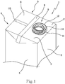
- Figure 1 shows an upper portion of a sealed package 1 particularly suitable for containing a pourable product, for example a pourable food product.
- the package 1 may be produced by folding and sealing a basic unit made from a sheet packaging material.
- the basic unit may be a portion of a sheet packaging material comprising a succession of basic units.
- the sheet packaging material has a multilayer structure comprising a base layer, e.g. of paper, for stiffness, and a number of lamination layers covering both sides of the base layer.
- a base layer e.g. of paper
- lamination layers covering both sides of the base layer.
- the sheet packaging material may comprise a base layer interposed between at least two heat-sealable layers.
- the lamination layers may comprise a first layer of oxygen-barrier material, e.g. an aluminium foil, and a number of second layers of heat-sealable plastic material covering both sides of both base layer and first layer.
- a first layer of oxygen-barrier material e.g. an aluminium foil
- second layers of heat-sealable plastic material covering both sides of both base layer and first layer.
- such solution comprises, in succession and from the side eventually forming the inside of a package, a layer of heat-sealable plastic material, a layer of barrier material, another layer of heat-sealable plastic material, a base layer, and another layer of heat-sealable plastic material.
- the oxygen-barrier layer may be made of a non-electrically conducting material, such as EVOH.
- the package 1 comprises a bottom wall that is not shown, which during use is intended to rest on a supporting surface, such as a shelf or a table, and a top wall 2 opposite the bottom wall.
- a supporting surface such as a shelf or a table
- a top wall 2 opposite the bottom wall.
- the top wall 2 is tilted relative to the bottom wall.
- the bottom wall and the top wall 2 are parallel to one another.
- the package 1 further comprises a front wall 3, which is interposed between the bottom wall and the top wall 2, and a back wall 4, opposite the front wall 3.
- Two side walls 5, which are opposite one another, are interposed between the front wall 3 and the back wall 4.
- the package 1 further comprises a top transverse sealing band 6 that extends across the top wall 2, between opposite edges thereof.
- a similar bottom transverse sealing band which is not shown in Figure 1 , extends across the bottom wall of the package 1, between opposite edges thereof.
- the top transverse sealing band 6 divides the top wall 2 into a first wall portion 7 and a second wall portion 8.
- the first wall portion 7, which is adjacent to the front wall 3, defines an area on which an opening device 9, particularly a reclosable opening device, may be applied.
- the opening device 9 comprises a pouring spout 10 that is fixed relative to the package 1.
- the pouring spout 10 may be applied onto the packaging material forming the package 1 before folding such packaging material, e.g. by moulding the pouring spout 10 directly on the sheet packaging material, or by other conventional fastening systems, such as adhesives, or by microflame, electric-current-induction, ultrasonic, laser, or other heat-sealing techniques.
- the pouring spout 10 comprises a neck 11 protruding upwards from the top wall 2.
- a lid that is not shown may be applied after the package has been formed.
- the lid is removably connected to the neck 11, e.g. by means of a threaded connection.
- the second wall portion 8, which is adjacent to the back wall 4, comprises, in a center region thereof, an end portion of a flat longitudinal sealing band 13 of the package 1.
- the longitudinal sealing band 13 extends perpendicularly between the top transverse sealing band 6 and the bottom transverse sealing band, and substantially along the centerline of the back wall 4.
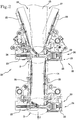
- Figure 2 shows an assembly 20 that can be used for producing sealed packaging units 14 from the sheet packaging material.
- the sealed packaging units 14 can then be subjected to further folding operations in a folding device that is not shown, the folding device being located downstream of the assembly 20.
- a package 1 as shown in Figure 1 is obtained from each sealed packaging unit 14.
- the assembly 20 comprises an advancement device 21 for advancing the sheet packaging material along an advancement direction F.
- the advancement device 21 comprises two pairs 24 of gripping jaws, each pair of gripping jaws being configured to engage with a portion of the sheet packaging material intended to form an end region of the sealed packaging unit 14.
- each pair 24 of gripping jaws comprises a first jaw 22 and a second jaw 23 located opposite one another, as will be set out in greater detail hereinbelow.
- the first jaw 22 and the second jaw 23 are movable between a gripping position, shown in Figure 2 and a disengagement position that is not shown.
- the first jaw 22 and the second jaw 23 clamp a portion of sheet packaging material therebetween, so that, by advancing the first jaw 22 and the second jaw 23 along the advancement direction F, the sheet packaging material is simultaneously advanced along the advancement direction F.
- the disengagement position the first jaw 22 and the second jaw 23 are spaced apart from one another, so that the sheet packaging material can be moved relative to the first jaw 22 and to the second jaw 23.
- the first jaw 22 and the second jaw 23 of each pair 24 are configured to be advanced in the advancement direction F by a driving device that is not shown.
- the driving device may comprise, for example, a driving shaft connected to each pair 24 of jaws.
- the driving device may comprise a driving chain supporting the first jaws 22 and a further driving chain supporting the second jaws 23.
- Other kinds of driving device can, as an alternative, be successfully used.
- the assembly 20 is intended to receive the sheet packaging material conformed as a continuous web.
- the assembly 20 comprises a longitudinal sealing device, which is not shown in the drawings, for sealing opposite longitudinal borders of the sheet packaging material, so as to form from the sheet packaging material a continuous tube 15 extending along the advancement direction F. More in detail, the longitudinal sealing device is intended to join the opposite longitudinal borders of the sheet packaging material along a continuous longitudinal sealing band that will define, in the finished package 1, the longitudinal sealing band 13.
- the longitudinal sealing device is located upstream of the advancement device 21, so that the advancement device 21 acts on the sheet packaging material when the latter is already conformed as a continuous tube 15.
- the assembly 20 may further comprise a filling device that is not shown, for filling the continuous tube 15 with the product that the packages 1 are intended to contain. Also the filling device is located upstream of the advancement device 21 so that, when the continuous tube 15 is gripped by the advancement device 21, the continuous tube 15 is already filled with the product.
- a volume defining element is connected to each jaw 22, 23 of each pair 24.
- each half-shell 25 may be hinged or pivotally connected, for example at a lower end thereof, to the corresponding jaw.
- the half-shells 25 may exert a preliminary forming action on the continuous tube 15, by folding the sheet packaging material forming the continuous tube 15 along some crease lines obtained on the sheet packaging material.
- the advancement device 21, which comprises the jaws 22, 24 and the corresponding half-shells 25, is therefore configured not only to advance the sheet packaging material along the advancement direction F, but also to form the sheet packaging material by starting to fold the latter.
- the advancement device 21 can thus be considered as an advancement and forming device.
- the half-shells 25 connected to the jaws of a pair 24 are operable between an active position, shown in the lower part of Figure 2 , and an inactive position shown in the upper part of Figure 2 .
- the half-shells 25 are close to one another and interact with the continuous tube 15 so as to squeeze the latter and isolate a preset volume inside each sealed packaging unit 14. This preset volume corresponds to the quantity of product that will be contained inside each package 1.
- the half-shells 25 may further exert a preliminary folding action on the continuous tube 15, by acting on a plurality of longitudinal crease lines of the packaging material forming the continuous tube 15.
- the half-shells 25 are spaced apart from one another and do not interact with the continuous tube 15.
- the half-shells 25 move from the active position to the inactive position by rotating around a respective pivot point relative to the corresponding jaw 22, 23.
- the active position can be considered as a closed position of the half-shells 25, whereas the inactive position may be considered as an open position of the half-shells 25.
- Each half-shell 25 has a concave cross-section in a plane perpendicular to the advancement direction F. Hence, when the half-shells 25 connected to the jaws of a pair 24 are in the active position, the continuous tube 15 is encircled by the half-shells 25.
- the packaging material forming the continuous tube 15 is provided with a plurality of pouring spouts 10 of respective opening devices 9.
- the necks 11 of consecutive pouring spouts 10 are equally spaced along the advancement direction F.
- Consecutive pouring spouts 10 are aligned along the advancement direction F, so that, after the continuous tube 15 has been formed, all the pouring spouts 10 are located on the same side of the continuous tube 15.
- two opposite main sides may be defined, namely a side 27 and a further side 28.
- the longitudinal sealing band 13 is located on the side 27 of the continuous tube 15, whereas the pouring spouts 10 are located on the further side 28 of the continuous tube 15.
- the longitudinal sealing band 13 and the pouring spouts 10 are located on opposite sides of the continuous tube 15.
- the assembly 20 further comprises at least one transverse sealing device 29 for sealing the continuous tube 15 transversely, in particular perpendicularly, to the advancement direction F. More in detail, two transverse sealing devices 29 are provided, arranged in sequence along the advancement direction F at a distance from one another. The transverse sealing devices 29 are configured to join, by sealing, the opposite sides 27, 28 of the continuous tube 15 respectively along the top transverse sealing band 6 and the bottom transverse sealing band. The continuous tube 15 is thus closed at its opposite ends, so that a sealed packaging unit 14 can be defined.
- each transverse sealing device 29 comprises a sealing element 30 for exerting a sealing action on the packaging material forming the continuous tube 15.
- Each transverse sealing device 29 further comprises an abutment element 31 against which the packaging material forming the continuous tube 15 may abut during sealing, i.e. while the sealing element 30 interacts with the packaging material.
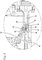
- each transverse sealing device 29 is an ultrasonic sealing device.
- the sealing element 30 is therefore a sonotrode for creating ultrasonic vibrations thereby generating vibrational energy, which is then applied to the packaging material forming the continuous tube 15.
- a transducer 32 for example of the piezoelectric type, is attached to the sealing element 30 for causing the latter to vibrate.
- transverse sealing device 29 might be used, for example of the induction sealing type, in which case the sealing element 30 would be an electric induction generating element for induction sealing the packaging material forming the continuous tube 15.
- the abutment element 31 is made of a resilient material and is delimited by a flat surface facing the continuous tube 15.
- the abutment element 31 faces the sealing element 29 and is delimited by an abutment surface 33, arranged substantially along the advancement direction F.
- the packaging material is intended to be pressed against the abutment surface 33 by the sealing element 30.
- the abutment surface 33 is not perfectly flat, but is delimited by a wavy profile for better adapting to the conformation of the overlapping ends of packaging material that are sealed together by the transverse sealing device 29.
- the sealing element 30 faces the abutment element 31.
- the packaging material forming the continuous tube 15 is interposed between the sealing element 30 and the abutment element 31 during sealing.
- the sealing element 30 and the abutment element 31 are located on opposite sides of the continuous tube 15.
- the sealing element 30 is so positioned as to face, during use, the longitudinal sealing band 13 on the continuous tube 15.
- the sealing element 30 is configured to act on the continuous tube 15 from the side 27.
- the abutment element 31 is instead positioned so as to face, during use, the side of the continuous tube 15 that is free of the longitudinal sealing band 13. In other words, the abutment element 31 is configured to interact with the continuous tube from the further side 28.
- the abutment element 31 therefore faces, during use, the side of the continuous tube 15 on which the pouring spouts 10 are applied.
- the sealing element 30 and the abutment element 31 are movable relative to one another between a sealing position, shown in Figures 2 to 4 , and a passive position that is not shown.
- the sealing position the sealing element 30 and the abutment element 31 are close to one another and actively interact with the packaging material forming the continuous tube 15 in order to seal facing portions of the packaging material.
- the packaging material forming the continuous tube 15 is pinched between the sealing element 30 and the abutment element 31 in the sealing position.
- the passive position the sealing element 30 and the abutment element 31 are spaced apart from one another, so as not to interfere with the continuous tube 15.
- the sealing element 30 and the abutment element 31 may be integrated in the gripping jaws of a pair 24. More in detail, the sealing element 30 may be included in the first jaw 22, whereas the abutment element 31 may be supported by the second jaw 23. In this case, the sealing element 30 and the abutment element 31 are arranged in the sealing position while the jaws of the corresponding pair 24 are arranged in the gripping position. On the other hand, when the jaws of the corresponding pair 24 are in the disengagement position, the sealing element 30 and the abutment element 31 are located in the passive position.
- the second jaw 23 is provided with a recess 34 for housing a neck 11 when the packaging material forming the continuous tube 15 is pressed between the abutment element 31 and the sealing element 30.
- the recess 34 may have a substantially circular or oval shape, when seen in plan view.
- the diameter of the recess 34 is greater than the diameter of the neck 11, so as to avoid risks of interference between the neck 11 and the walls of the recess 34, even if there are differences in position between consecutive necks 11 applied to a sheet packaging material.
- the recess 34 is obtained in a surface of the second jaw 23 facing the neck 11, i.e. (in the example shown) on an upper surface of the second jaw 23.
- a portion of the recess 34 that, in use, is located near the continuous tube 15, may be obtained in the abutment element 31.
- a further portion of the recess 34 that, in use, is located far from the continuous tube 15, may be obtained in a component 38 of the second jaw 23.
- the half-shell 25 connected to the second jaw 23 is hinged to the component 38.
- An intermediate portion of the recess 34, interposed between the above mentioned portion and further portion, may be made in a supporting component 39 of the second jaw 23, which supports the abutment element 31.
- the recess 34 may be delimited by a bottom surface 35, which is substantially parallel to an edge 12 of the neck 11, in a configuration in which the neck 11 is substantially completely received inside the recess 34.
- the recess 34 may be further delimited by a side surface 36, which is substantially perpendicular to the bottom surface 35 and hence substantially parallel to a lateral surface of the neck 11.
- a connection surface 37 may delimit the recess 34 at a location interposed between the bottom surface 35 and the side surface 36.
- the connection surface 37 is arranged near the abutment element 31.
- the recess 34 has a non-symmetrical configuration relative to an axis around which the side surface 36 extends.
- the connection surface 37 defines a part of the recess 34 that protrudes into the bottom surface 35, near the abutment element 31, i.e. in a portion of the bottom surface 35 nearest to the continuous tube 15. This part of the recess 34 ensures that interference between the second jaw 23 and the neck 10 is avoided, in any position in which the neck 10 may be while the continuous tube 15 is folded and sealed.
- the assembly 20 may further comprise a cutting device 40 for cutting the continuous tube 15 at equidistant lengths, so as to separate the sealed packaging units 14 one from another.
- the cutting device 40 comprises a cutting element, for example a blade 41 for interfering with the packaging material forming the continuous tube 15 and thereby cut the latter.
- the blade 41 is configured to cut the packaging material at the transverse sealing band created by the transverse sealing device 29. More in detail, the blade 41 is configured to divide the transverse sealing band in two portions, thereby originating the top transverse sealing band 6 of a first sealed packaging unit 14 intended to form a package 1 and the bottom transverse sealing band of a second sealed packaging unit 14 adjacent to the first sealed packaging unit 14.
- the blade 41 is at least partially housed in the abutment element 31. Hence, the blade 41 is so positioned as to face the further side 28 of the packaging material, i.e. the side of the continuous tube 15 opposite the longitudinal sealing band.
- the blade 41 comprises a thinned portion 42 for interacting with the packaging material in order to cut the latter and a thickened portion 43 from which the thinned portion 42 protrudes.
- a joining surface 44 is interposed between the thinned portion 42 and the thickened portion 43.
- the joining surface 44 connects the thinned portion 42 to the thickened portion 43.
- the joining surface 44 is adjacent to the recess 34, particularly to the bottom surface 35 thereof.
- the joining surface 44 may for example be a flat surface parallel to the bottom surface 35.
- the thickness of the blade 41 may be reduced near a cutting edge thereof.
- the overall dimensions of the blade 41 may therefore be limited, thereby decreasing the space needed to house the blade 41 in the abutment element 31. This allows the recess 34 to be made in the abutment element 31.
- the blade 41 is symmetrical relative to a plane perpendicular to the advancement direction F.
- the blade 41 is therefore delimited by a further joining surface 26, which is symmetrical with respect to the joining surface 44. While the joining surface 44 is adjacent to the recess 34, the further joining surface 26 is arranged on an opposite side with respect to the recess 34. This allows the blade 41 to be more easily manufactured and assembled on the packaging machine.
- the blade 41 may have a shape that is different from the shape shown in Figures 2 to 4 .
- a movement device which is not shown, is provided for moving the blade 41 between an advanced position, shown in Figures 3 and 4 , and a retracted position that is not shown. In the advanced position, the blade 41 protrudes from the abutment surface 33 and interferes with the packaging material forming the continuous tube 15, which can thereby be cut.
- a seat 45 can be provided on the sealing element 30 for housing a cutting end of the blade 41 in the advanced position, i.e. during cutting.
- the blade 41 In the retracted position, the blade 41 does not protrude from the abutment surface 33, so that there is no interference between the blade 41 and the packaging material forming the continuous tube 15.
- the blade 41 In order to move from the retracted position to the advanced position or vice versa, the blade 41 is displaced in a direction arranged transversely to, in particular perpendicularly to, the advancement direction F.
- the sheet packaging material is folded and sealed parallelly to the advancement direction F by the longitudinal sealing device, so as to form the continuous tube 15. This occurs while the sheet packaging material is being advanced along the advancement direction F by the advancement device 21.
- the packaging material forming the continuous tube 15 is successively gripped at two distinct and consecutive locations by the two pairs 24 of gripping jaws, which are in the gripping position and advance the continuous tube 15 along the advancement direction F.
- the jaws of a pair 24, in the gripping position move forwards in the advancement direction F to advance the continuous tube 15
- the jaws of the other pair 24, in the disengagement position move backwards in a direction opposite the advancement direction F, so as to reach a new portion of the continuous tube 15 to be gripped, located upstream of the previously gripped portion.
- the filling device introduces the product intended to fill the packages 1 inside the continuous tube 15, before the latter starts to interact with the pairs 24 of jaws.
- transverse sealing device 29 associated to each pair 24 of jaws forms a corresponding transverse sealing band, so that the two consecutive transverse sealing devices 29, one after the other, seal a portion of the continuous tube 15 at both ends thereof, thereby forming a sealed packaging unit 14.
- the blade 41 associated to a pair 24 of jaws is displaced into the advanced position, so as to cut the packaging material forming the continuous tube 15 through the respective transverse sealing band and separate the sealed packaging units 14 one from another.
- two facing half-shells 25, which were initially in the inactive position as shown in the upper part of Figure 2 , are brought into the active position as shown in the lower part of Figure 2 .
- the continuous tube 15 is thus squeezed between the two facing half-shells 25, so that a preset volume of filling product can be isolated in each sealed packaging unit 14.
- the facing half-shells 25 may exert a preliminary folding action on at least some of the crease lines present in the sheet packaging material forming the continuous tube 15.
- the half-shells 25 associated to a pair 24 of jaws are each rotated around the respective pivot point at which each half-shell 25 is hinged to the respective jaw.
Landscapes
- Engineering & Computer Science (AREA)
- Mechanical Engineering (AREA)
- Containers And Plastic Fillers For Packaging (AREA)
- Package Closures (AREA)
- Lining Or Joining Of Plastics Or The Like (AREA)
Claims (11)
- Anordnung zum Herstellen abgedichteter Verpackungseinheiten (14) aus einem bahnförmigen Verpackungsmaterial, umfassend:- eine Vorschubvorrichtung (21) zum Vorschieben des bahnförmigen Verpackungsmaterials entlang einer Vorschubrichtung (F),- eine längsverlaufende Dichtungsvorrichtung zum Abdichten gegenüberliegender Ränder des bahnförmigen Verpackungsmaterials entlang eines längsverlaufenden Dichtungsbands, das parallel zu der Vorschubrichtung (F) angeordnet ist, wodurch eine durchgehende Röhre (15) ausgebildet wird,- eine querverlaufende Dichtungsvorrichtung (29) zum Abdichten der durchgehenden Röhre (15) quer zu der Vorschubrichtung (F), um eine abgedichtete Verpackungseinheit (14) zu definieren,wobei die querverlaufende Dichtungsvorrichtung (29) ein Dichtungselement (30) und ein Anschlagelement (31) umfasst, die vorgesehen sind, während eines Abdichtens miteinander zusammenzuwirken, während sie sich an entgegengesetzten Seiten der durchgehenden Röhre (15) befinden, wobei die querverlaufende Dichtungsvorrichtung (29) eine Ultraschalldichtungsvorrichtung ist und das Dichtungselement (30) eine Sonotrode ist, dadurch gekennzeichnet, dass das Dichtungselement (30) derart ausgestaltet ist, dass es auf eine Seite (27) der durchgehenden Röhre (15) wirkt, an der das längsverlaufende Dichtungsband bereitgestellt ist, dass die querverlaufende Dichtungsvorrichtung (29) eine Aussparung (34) aufweist, die vorgesehen ist, während eines Abdichtens einen Hals (10) einer Ausgussrinne (11) aufzunehmen, der auf die durchgehende Röhre (15) aufgebracht wird, und dass die Aussparung (34) zumindest teilweise in dem Anschlagelement (31) hergestellt ist.
- Anordnung nach Anspruch 1, wobei die Aussparung (34) durch eine untere Fläche (35), die vorgesehen ist, einer Kante (12) des Halses (10) zugewandt zu sein, und durch eine Seitenfläche (36), die vorgesehen ist, den Hals (10) zu umgeben, begrenzt ist.
- Anordnung nach Anspruch 2, wobei die Aussparung (34) eine asymmetrische Ausgestaltung aufgrund dessen aufweist, dass ein Teil der Aussparung (34) hin zu dem Anschlagelement (31) hervorragt, wobei der Teil vorgesehen ist, eine Interferenz zwischen dem Hals (10) und dem Anschlagelement (31) zu verhindern.
- Anordnung nach einem der vorhergehenden Ansprüche, wobei die Vorschubvorrichtung (21) ein Paar (24) von Greifbacken zum Greifen der durchgehenden Röhre (15) umfasst, wobei das Paar (24) von Greifbacken eine erste Backe (22), in die das Dichtungselement (30) integriert ist, und eine zweite Backe (23), in die das Anschlagelement (31) integriert ist, umfasst.
- Anordnung nach Anspruch 4, wobei die Aussparung (34) in der zweiten Backe (23) hergestellt ist.
- Anordnung nach Anspruch 4 oder 5, und ferner umfassend ein Paar von Halbschalen (25), von denen jede mit einer Greifbacke des Paars (24) verbunden ist, wobei die Halbschalen (25) in eine aktive Position verschiebbar sind, um ein voreingestelltes Volumen in einem Abschnitt der durchgehenden Röhre (15) zu isolieren, das vorgesehen ist, eine abgedichtete Verpackungseinheit (14) zu definieren.
- Anordnung nach einem der vorhergehenden Ansprüche, und ferner umfassend eine Schneidvorrichtung (40) zum Schneiden der durchgehenden Röhre (15), um davon aufeinanderfolgende abgedichtete Verpackungseinheiten (14) zu trennen.
- Anordnung nach Anspruch 7, wobei die Schneidvorrichtung (40) eine Klinge (41) umfasst, die zumindest teilweise in dem Anschlagelement (31) aufgenommen ist.
- Anordnung nach Anspruch 8, wobei die Klinge einen ausgedünnten Abschnitt (42), der durch eine Schneidkante begrenzt ist, und einen verdickten Abschnitt (43), von dem der ausgedünnte Abschnitt (42) hervorsteht, umfasst.
- Anordnung nach Anspruch 8 oder 9, wobei das Dichtungselement (30) einen der Klinge (41) zugewandten Sitz (45) zum Empfangen eines Schneidendes der Klinge (41) während eines Schneidens aufweist.
- Anordnung nach einem der vorhergehenden Ansprüche, wobei die Vorschubvorrichtung (21) ausgestaltet ist, eine vorläufige formende Wirkung auf das bahnförmige Verpackungsmaterial aufzubringen
Priority Applications (5)
| Application Number | Priority Date | Filing Date | Title |
|---|---|---|---|
| EP16167410.6A EP3238918B1 (de) | 2016-04-28 | 2016-04-28 | Anordnung zur herstellung versiegelter verpackungseinheiten |
| CN201780025694.6A CN109070484B (zh) | 2016-04-28 | 2017-04-12 | 生产密封包装单元的组件 |
| JP2018555985A JP7343979B2 (ja) | 2016-04-28 | 2017-04-12 | 密封パッケージユニットを製造するための組立体 |
| PCT/EP2017/058794 WO2017186493A1 (en) | 2016-04-28 | 2017-04-12 | An assembly for producing sealed packaging units |
| US16/096,993 US11597553B2 (en) | 2016-04-28 | 2017-04-12 | Assembly for producing sealed packaging units |
Applications Claiming Priority (1)
| Application Number | Priority Date | Filing Date | Title |
|---|---|---|---|
| EP16167410.6A EP3238918B1 (de) | 2016-04-28 | 2016-04-28 | Anordnung zur herstellung versiegelter verpackungseinheiten |
Publications (2)
| Publication Number | Publication Date |
|---|---|
| EP3238918A1 EP3238918A1 (de) | 2017-11-01 |
| EP3238918B1 true EP3238918B1 (de) | 2020-06-17 |
Family
ID=55910142
Family Applications (1)
| Application Number | Title | Priority Date | Filing Date |
|---|---|---|---|
| EP16167410.6A Active EP3238918B1 (de) | 2016-04-28 | 2016-04-28 | Anordnung zur herstellung versiegelter verpackungseinheiten |
Country Status (5)
| Country | Link |
|---|---|
| US (1) | US11597553B2 (de) |
| EP (1) | EP3238918B1 (de) |
| JP (1) | JP7343979B2 (de) |
| CN (1) | CN109070484B (de) |
| WO (1) | WO2017186493A1 (de) |
Families Citing this family (1)
| Publication number | Priority date | Publication date | Assignee | Title |
|---|---|---|---|---|
| WO2021001144A1 (en) * | 2019-07-01 | 2021-01-07 | Tetra Laval Holdings & Finance S.A. | A packaging assembly for forming and sealing a plurality of packs containing a pourable product and a method for forming and sealing a plurality of packs |
Family Cites Families (17)
| Publication number | Priority date | Publication date | Assignee | Title |
|---|---|---|---|---|
| US3894381A (en) * | 1973-06-21 | 1975-07-15 | Inpaco | Method and means for attaching fitments to a bag or pouch on a packaging machine |
| JP3057902B2 (ja) * | 1992-05-28 | 2000-07-04 | 凸版印刷株式会社 | 口栓付フラットトップ型液体紙容器のトップシール方法 |
| DE19651242A1 (de) * | 1996-12-10 | 1998-06-18 | Tetra Laval Holdings & Finance | Amboß einer Ultraschall-Siegeleinheit |
| DK1241099T3 (da) * | 2001-03-12 | 2004-05-03 | Tetra Laval Holdings & Finance | Ultrasonisk forseglingsindretning til forsegling af emballager af hældbare fødevarer |
| ES2305047T3 (es) * | 2001-06-18 | 2008-11-01 | TETRA LAVAL HOLDINGS & FINANCE SA | Dispositivo de sellado por induccion para material de envasar termosellable. |
| US6718739B2 (en) | 2002-04-05 | 2004-04-13 | Frito-Lay North America, Inc. | Tube pack bag making |
| US20030196411A1 (en) * | 2002-04-19 | 2003-10-23 | Schroeder Alfred A. | Flexible packaging |
| SE528872C2 (sv) * | 2005-07-08 | 2007-03-06 | Tetra Laval Holdings & Finance | Anordning och förfarande för tvärförsegling |
| ITBO20050511A1 (it) * | 2005-07-29 | 2005-10-28 | Azionaria Costruzioni Acma Spa | Dispositivo di saldatura ad ultrasuoni di nastri tubolari continui |
| SE529801C2 (sv) * | 2006-03-31 | 2007-11-27 | Tetra Laval Holdings & Finance | Formningsanordning, maskin, formningsförfarande och process vid tillverkning av förpackningar |
| JP5240809B2 (ja) * | 2006-03-31 | 2013-07-17 | 日本テトラパック株式会社 | シール装置、包装充填装置及びシール方法 |
| EP2151390B1 (de) | 2008-08-09 | 2015-09-30 | Tetra Laval Holdings & Finance S.A. | Verpackungsverfahren und -einheit zur Herstellung versiegelter Verpackungen eines Lebensmittelprodukts, das in ein Rohr aus Verpackungsmaterial gegossen werden kann |
| ES2376824T3 (es) * | 2009-03-30 | 2012-03-20 | Tetra Laval Holdings & Finance Sa | Elemento sellador para termosellar material envasador para producir envases sellados de productos alimenticios capaces de ser vertidos dentro de un tubo de material envasador |
| EP2468480B1 (de) * | 2010-12-23 | 2018-08-08 | Tetra Laval Holdings & Finance S.A. | Induktionsversiegelungsvorrichtung für Wärmeversiegelungsverpackungsmaterial zur Herstellung versiegelter Verpackungen für gießbare Lebensmittel |
| JP5330551B2 (ja) | 2012-01-13 | 2013-10-30 | 株式会社東芝 | 電子機器および表示処理方法 |
| EP2662291B1 (de) * | 2012-05-11 | 2014-10-15 | Tetra Laval Holdings & Finance S.A. | Verpackungseinheit und Verfahren zur Herstellung versiegelter Verpackungen |
| EP3000584B1 (de) * | 2014-09-23 | 2018-12-26 | Tetra Laval Holdings & Finance S.A. | Versiegelungselement zur Versiegelung mit Wärme von Verpackungsmaterial zur Herstellung versiegelter Verpackungen |
-
2016
- 2016-04-28 EP EP16167410.6A patent/EP3238918B1/de active Active
-
2017
- 2017-04-12 CN CN201780025694.6A patent/CN109070484B/zh active Active
- 2017-04-12 US US16/096,993 patent/US11597553B2/en active Active
- 2017-04-12 WO PCT/EP2017/058794 patent/WO2017186493A1/en active Application Filing
- 2017-04-12 JP JP2018555985A patent/JP7343979B2/ja active Active
Non-Patent Citations (1)
| Title |
|---|
| None * |
Also Published As
| Publication number | Publication date |
|---|---|
| CN109070484B (zh) | 2021-09-10 |
| CN109070484A (zh) | 2018-12-21 |
| JP2019514799A (ja) | 2019-06-06 |
| US11597553B2 (en) | 2023-03-07 |
| US20190135470A1 (en) | 2019-05-09 |
| EP3238918A1 (de) | 2017-11-01 |
| WO2017186493A1 (en) | 2017-11-02 |
| JP7343979B2 (ja) | 2023-09-13 |
Similar Documents
| Publication | Publication Date | Title |
|---|---|---|
| JP5525514B2 (ja) | 食品の密封パッケージを製造するためのシール用顎状掴み具、及びこれを備えた包装機 | |
| EP3437841B1 (de) | Amboss zur transversalen versiegelung eines schlauchs eines verpackungsmaterials und siegelbacke mit einem amboss | |
| EP3000584B1 (de) | Versiegelungselement zur Versiegelung mit Wärme von Verpackungsmaterial zur Herstellung versiegelter Verpackungen | |
| EP2917021B1 (de) | Heissversiegelungsvorrichtung | |
| JP6461827B2 (ja) | ソノトロード | |
| CN107922060B (zh) | 一种用于将盖施加于容器上的施加单元 | |
| US10293972B2 (en) | Opening device and apparatus for moulding an opening device on a sheet packaging material | |
| JP2002326294A (ja) | 流動食品を充填された包装材料の壁部をシールする超音波横断シール装置および方法 | |
| JP4093775B2 (ja) | 流動食品を充填された包装材料の壁部をシールする超音波横断シール装置 | |
| EP2923959B1 (de) | Falteinheit zur Herstellung von Verpackungen für Lebensmittelprodukte, die aus versiegelten Verpackungen in ein Tubenverpackungsmaterial gegossen werden können | |
| JP4025098B2 (ja) | 流動食品のパッケージをシールする超音波シール装置 | |
| CN107922062B (zh) | 用于将盖施加于容器上的方法和施加头 | |
| EP3238918B1 (de) | Anordnung zur herstellung versiegelter verpackungseinheiten | |
| WO2003022708A1 (en) | Stand-up pouch for packaging food products | |
| EP3219631B1 (de) | Vorrichtung und verfahren zur formung einer packung in eine fertigpackung, falteinheit zur herstellung versiegelter packungen für giessbare lebensmittelprodukte | |
| EP4357255A1 (de) | Falzapparat und verpackungsmaschine mit einem falzapparat | |
| CN116323157A (zh) | 压力元件和具有压力元件的用于包装组件的密封设备 | |
| EP3318500A1 (de) | Aufbringungsvorrichtung und verfahren zum auftragen von öffnungsvorrichtungen auf packungen |
Legal Events
| Date | Code | Title | Description |
|---|---|---|---|
| PUAI | Public reference made under article 153(3) epc to a published international application that has entered the european phase |
Free format text: ORIGINAL CODE: 0009012 |
|
| STAA | Information on the status of an ep patent application or granted ep patent |
Free format text: STATUS: THE APPLICATION HAS BEEN PUBLISHED |
|
| AK | Designated contracting states |
Kind code of ref document: A1 Designated state(s): AL AT BE BG CH CY CZ DE DK EE ES FI FR GB GR HR HU IE IS IT LI LT LU LV MC MK MT NL NO PL PT RO RS SE SI SK SM TR |
|
| AX | Request for extension of the european patent |
Extension state: BA ME |
|
| STAA | Information on the status of an ep patent application or granted ep patent |
Free format text: STATUS: REQUEST FOR EXAMINATION WAS MADE |
|
| 17P | Request for examination filed |
Effective date: 20180502 |
|
| RBV | Designated contracting states (corrected) |
Designated state(s): AL AT BE BG CH CY CZ DE DK EE ES FI FR GB GR HR HU IE IS IT LI LT LU LV MC MK MT NL NO PL PT RO RS SE SI SK SM TR |
|
| GRAP | Despatch of communication of intention to grant a patent |
Free format text: ORIGINAL CODE: EPIDOSNIGR1 |
|
| STAA | Information on the status of an ep patent application or granted ep patent |
Free format text: STATUS: GRANT OF PATENT IS INTENDED |
|
| RIC1 | Information provided on ipc code assigned before grant |
Ipc: B29K 23/00 20060101ALN20200117BHEP Ipc: B65D 5/74 20060101ALN20200117BHEP Ipc: B29C 65/74 20060101ALI20200117BHEP Ipc: B29K 705/02 20060101ALN20200117BHEP Ipc: B29C 65/08 20060101AFI20200117BHEP Ipc: B29L 9/00 20060101ALN20200117BHEP Ipc: B65B 51/30 20060101ALI20200117BHEP Ipc: B65B 61/18 20060101ALI20200117BHEP Ipc: B29K 711/12 20060101ALN20200117BHEP Ipc: B29C 65/78 20060101ALI20200117BHEP Ipc: B65B 51/22 20060101ALI20200117BHEP |
|
| INTG | Intention to grant announced |
Effective date: 20200206 |
|
| GRAS | Grant fee paid |
Free format text: ORIGINAL CODE: EPIDOSNIGR3 |
|
| GRAA | (expected) grant |
Free format text: ORIGINAL CODE: 0009210 |
|
| STAA | Information on the status of an ep patent application or granted ep patent |
Free format text: STATUS: THE PATENT HAS BEEN GRANTED |
|
| AK | Designated contracting states |
Kind code of ref document: B1 Designated state(s): AL AT BE BG CH CY CZ DE DK EE ES FI FR GB GR HR HU IE IS IT LI LT LU LV MC MK MT NL NO PL PT RO RS SE SI SK SM TR |
|
| REG | Reference to a national code |
Ref country code: GB Ref legal event code: FG4D |
|
| REG | Reference to a national code |
Ref country code: CH Ref legal event code: EP |
|
| REG | Reference to a national code |
Ref country code: IE Ref legal event code: FG4D |
|
| REG | Reference to a national code |
Ref country code: DE Ref legal event code: R096 Ref document number: 602016038088 Country of ref document: DE |
|
| REG | Reference to a national code |
Ref country code: AT Ref legal event code: REF Ref document number: 1280789 Country of ref document: AT Kind code of ref document: T Effective date: 20200715 |
|
| PG25 | Lapsed in a contracting state [announced via postgrant information from national office to epo] |
Ref country code: LT Free format text: LAPSE BECAUSE OF FAILURE TO SUBMIT A TRANSLATION OF THE DESCRIPTION OR TO PAY THE FEE WITHIN THE PRESCRIBED TIME-LIMIT Effective date: 20200617 Ref country code: GR Free format text: LAPSE BECAUSE OF FAILURE TO SUBMIT A TRANSLATION OF THE DESCRIPTION OR TO PAY THE FEE WITHIN THE PRESCRIBED TIME-LIMIT Effective date: 20200918 Ref country code: SE Free format text: LAPSE BECAUSE OF FAILURE TO SUBMIT A TRANSLATION OF THE DESCRIPTION OR TO PAY THE FEE WITHIN THE PRESCRIBED TIME-LIMIT Effective date: 20200617 Ref country code: NO Free format text: LAPSE BECAUSE OF FAILURE TO SUBMIT A TRANSLATION OF THE DESCRIPTION OR TO PAY THE FEE WITHIN THE PRESCRIBED TIME-LIMIT Effective date: 20200917 Ref country code: FI Free format text: LAPSE BECAUSE OF FAILURE TO SUBMIT A TRANSLATION OF THE DESCRIPTION OR TO PAY THE FEE WITHIN THE PRESCRIBED TIME-LIMIT Effective date: 20200617 |
|
| REG | Reference to a national code |
Ref country code: LT Ref legal event code: MG4D |
|
| REG | Reference to a national code |
Ref country code: NL Ref legal event code: MP Effective date: 20200617 |
|
| PG25 | Lapsed in a contracting state [announced via postgrant information from national office to epo] |
Ref country code: RS Free format text: LAPSE BECAUSE OF FAILURE TO SUBMIT A TRANSLATION OF THE DESCRIPTION OR TO PAY THE FEE WITHIN THE PRESCRIBED TIME-LIMIT Effective date: 20200617 Ref country code: HR Free format text: LAPSE BECAUSE OF FAILURE TO SUBMIT A TRANSLATION OF THE DESCRIPTION OR TO PAY THE FEE WITHIN THE PRESCRIBED TIME-LIMIT Effective date: 20200617 Ref country code: BG Free format text: LAPSE BECAUSE OF FAILURE TO SUBMIT A TRANSLATION OF THE DESCRIPTION OR TO PAY THE FEE WITHIN THE PRESCRIBED TIME-LIMIT Effective date: 20200917 Ref country code: LV Free format text: LAPSE BECAUSE OF FAILURE TO SUBMIT A TRANSLATION OF THE DESCRIPTION OR TO PAY THE FEE WITHIN THE PRESCRIBED TIME-LIMIT Effective date: 20200617 |
|
| REG | Reference to a national code |
Ref country code: AT Ref legal event code: MK05 Ref document number: 1280789 Country of ref document: AT Kind code of ref document: T Effective date: 20200617 |
|
| PG25 | Lapsed in a contracting state [announced via postgrant information from national office to epo] |
Ref country code: AL Free format text: LAPSE BECAUSE OF FAILURE TO SUBMIT A TRANSLATION OF THE DESCRIPTION OR TO PAY THE FEE WITHIN THE PRESCRIBED TIME-LIMIT Effective date: 20200617 Ref country code: NL Free format text: LAPSE BECAUSE OF FAILURE TO SUBMIT A TRANSLATION OF THE DESCRIPTION OR TO PAY THE FEE WITHIN THE PRESCRIBED TIME-LIMIT Effective date: 20200617 |
|
| PG25 | Lapsed in a contracting state [announced via postgrant information from national office to epo] |
Ref country code: PT Free format text: LAPSE BECAUSE OF FAILURE TO SUBMIT A TRANSLATION OF THE DESCRIPTION OR TO PAY THE FEE WITHIN THE PRESCRIBED TIME-LIMIT Effective date: 20201019 Ref country code: RO Free format text: LAPSE BECAUSE OF FAILURE TO SUBMIT A TRANSLATION OF THE DESCRIPTION OR TO PAY THE FEE WITHIN THE PRESCRIBED TIME-LIMIT Effective date: 20200617 Ref country code: CZ Free format text: LAPSE BECAUSE OF FAILURE TO SUBMIT A TRANSLATION OF THE DESCRIPTION OR TO PAY THE FEE WITHIN THE PRESCRIBED TIME-LIMIT Effective date: 20200617 Ref country code: ES Free format text: LAPSE BECAUSE OF FAILURE TO SUBMIT A TRANSLATION OF THE DESCRIPTION OR TO PAY THE FEE WITHIN THE PRESCRIBED TIME-LIMIT Effective date: 20200617 Ref country code: EE Free format text: LAPSE BECAUSE OF FAILURE TO SUBMIT A TRANSLATION OF THE DESCRIPTION OR TO PAY THE FEE WITHIN THE PRESCRIBED TIME-LIMIT Effective date: 20200617 Ref country code: SM Free format text: LAPSE BECAUSE OF FAILURE TO SUBMIT A TRANSLATION OF THE DESCRIPTION OR TO PAY THE FEE WITHIN THE PRESCRIBED TIME-LIMIT Effective date: 20200617 Ref country code: AT Free format text: LAPSE BECAUSE OF FAILURE TO SUBMIT A TRANSLATION OF THE DESCRIPTION OR TO PAY THE FEE WITHIN THE PRESCRIBED TIME-LIMIT Effective date: 20200617 |
|
| PG25 | Lapsed in a contracting state [announced via postgrant information from national office to epo] |
Ref country code: SK Free format text: LAPSE BECAUSE OF FAILURE TO SUBMIT A TRANSLATION OF THE DESCRIPTION OR TO PAY THE FEE WITHIN THE PRESCRIBED TIME-LIMIT Effective date: 20200617 Ref country code: PL Free format text: LAPSE BECAUSE OF FAILURE TO SUBMIT A TRANSLATION OF THE DESCRIPTION OR TO PAY THE FEE WITHIN THE PRESCRIBED TIME-LIMIT Effective date: 20200617 Ref country code: IS Free format text: LAPSE BECAUSE OF FAILURE TO SUBMIT A TRANSLATION OF THE DESCRIPTION OR TO PAY THE FEE WITHIN THE PRESCRIBED TIME-LIMIT Effective date: 20201017 |
|
| REG | Reference to a national code |
Ref country code: DE Ref legal event code: R097 Ref document number: 602016038088 Country of ref document: DE |
|
| PLBE | No opposition filed within time limit |
Free format text: ORIGINAL CODE: 0009261 |
|
| STAA | Information on the status of an ep patent application or granted ep patent |
Free format text: STATUS: NO OPPOSITION FILED WITHIN TIME LIMIT |
|
| PG25 | Lapsed in a contracting state [announced via postgrant information from national office to epo] |
Ref country code: DK Free format text: LAPSE BECAUSE OF FAILURE TO SUBMIT A TRANSLATION OF THE DESCRIPTION OR TO PAY THE FEE WITHIN THE PRESCRIBED TIME-LIMIT Effective date: 20200617 |
|
| 26N | No opposition filed |
Effective date: 20210318 |
|
| PG25 | Lapsed in a contracting state [announced via postgrant information from national office to epo] |
Ref country code: SI Free format text: LAPSE BECAUSE OF FAILURE TO SUBMIT A TRANSLATION OF THE DESCRIPTION OR TO PAY THE FEE WITHIN THE PRESCRIBED TIME-LIMIT Effective date: 20200617 |
|
| PG25 | Lapsed in a contracting state [announced via postgrant information from national office to epo] |
Ref country code: MC Free format text: LAPSE BECAUSE OF FAILURE TO SUBMIT A TRANSLATION OF THE DESCRIPTION OR TO PAY THE FEE WITHIN THE PRESCRIBED TIME-LIMIT Effective date: 20200617 |
|
| GBPC | Gb: european patent ceased through non-payment of renewal fee |
Effective date: 20210428 |
|
| PG25 | Lapsed in a contracting state [announced via postgrant information from national office to epo] |
Ref country code: LU Free format text: LAPSE BECAUSE OF NON-PAYMENT OF DUE FEES Effective date: 20210428 |
|
| REG | Reference to a national code |
Ref country code: BE Ref legal event code: MM Effective date: 20210430 |
|
| PG25 | Lapsed in a contracting state [announced via postgrant information from national office to epo] |
Ref country code: LI Free format text: LAPSE BECAUSE OF NON-PAYMENT OF DUE FEES Effective date: 20210430 Ref country code: CH Free format text: LAPSE BECAUSE OF NON-PAYMENT OF DUE FEES Effective date: 20210430 Ref country code: FR Free format text: LAPSE BECAUSE OF NON-PAYMENT OF DUE FEES Effective date: 20210430 Ref country code: GB Free format text: LAPSE BECAUSE OF NON-PAYMENT OF DUE FEES Effective date: 20210428 |
|
| PG25 | Lapsed in a contracting state [announced via postgrant information from national office to epo] |
Ref country code: IE Free format text: LAPSE BECAUSE OF NON-PAYMENT OF DUE FEES Effective date: 20210428 |
|
| PG25 | Lapsed in a contracting state [announced via postgrant information from national office to epo] |
Ref country code: IS Free format text: LAPSE BECAUSE OF FAILURE TO SUBMIT A TRANSLATION OF THE DESCRIPTION OR TO PAY THE FEE WITHIN THE PRESCRIBED TIME-LIMIT Effective date: 20201017 |
|
| PG25 | Lapsed in a contracting state [announced via postgrant information from national office to epo] |
Ref country code: BE Free format text: LAPSE BECAUSE OF NON-PAYMENT OF DUE FEES Effective date: 20210430 |
|
| PG25 | Lapsed in a contracting state [announced via postgrant information from national office to epo] |
Ref country code: HU Free format text: LAPSE BECAUSE OF FAILURE TO SUBMIT A TRANSLATION OF THE DESCRIPTION OR TO PAY THE FEE WITHIN THE PRESCRIBED TIME-LIMIT; INVALID AB INITIO Effective date: 20160428 |
|
| P01 | Opt-out of the competence of the unified patent court (upc) registered |
Effective date: 20230426 |
|
| PG25 | Lapsed in a contracting state [announced via postgrant information from national office to epo] |
Ref country code: CY Free format text: LAPSE BECAUSE OF FAILURE TO SUBMIT A TRANSLATION OF THE DESCRIPTION OR TO PAY THE FEE WITHIN THE PRESCRIBED TIME-LIMIT Effective date: 20200617 |
|
| PG25 | Lapsed in a contracting state [announced via postgrant information from national office to epo] |
Ref country code: MK Free format text: LAPSE BECAUSE OF FAILURE TO SUBMIT A TRANSLATION OF THE DESCRIPTION OR TO PAY THE FEE WITHIN THE PRESCRIBED TIME-LIMIT Effective date: 20200617 |
|
| PGFP | Annual fee paid to national office [announced via postgrant information from national office to epo] |
Ref country code: DE Payment date: 20240429 Year of fee payment: 9 |
|
| PGFP | Annual fee paid to national office [announced via postgrant information from national office to epo] |
Ref country code: IT Payment date: 20240423 Year of fee payment: 9 |