EP3238667B1 - Liner zum überziehen über einen gliedmassenstumpf - Google Patents
Liner zum überziehen über einen gliedmassenstumpf Download PDFInfo
- Publication number
- EP3238667B1 EP3238667B1 EP16166902.3A EP16166902A EP3238667B1 EP 3238667 B1 EP3238667 B1 EP 3238667B1 EP 16166902 A EP16166902 A EP 16166902A EP 3238667 B1 EP3238667 B1 EP 3238667B1
- Authority
- EP
- European Patent Office
- Prior art keywords
- liner
- region
- height
- circumferential
- height value
- Prior art date
- Legal status (The legal status is an assumption and is not a legal conclusion. Google has not performed a legal analysis and makes no representation as to the accuracy of the status listed.)
- Active
Links
Images



Classifications
-
- A—HUMAN NECESSITIES
- A61—MEDICAL OR VETERINARY SCIENCE; HYGIENE
- A61F—FILTERS IMPLANTABLE INTO BLOOD VESSELS; PROSTHESES; DEVICES PROVIDING PATENCY TO, OR PREVENTING COLLAPSING OF, TUBULAR STRUCTURES OF THE BODY, e.g. STENTS; ORTHOPAEDIC, NURSING OR CONTRACEPTIVE DEVICES; FOMENTATION; TREATMENT OR PROTECTION OF EYES OR EARS; BANDAGES, DRESSINGS OR ABSORBENT PADS; FIRST-AID KITS
- A61F2/00—Filters implantable into blood vessels; Prostheses, i.e. artificial substitutes or replacements for parts of the body; Appliances for connecting them with the body; Devices providing patency to, or preventing collapsing of, tubular structures of the body, e.g. stents
- A61F2/50—Prostheses not implantable in the body
- A61F2/78—Means for protecting prostheses or for attaching them to the body, e.g. bandages, harnesses, straps, or stockings for the limb stump
- A61F2/7812—Interface cushioning members placed between the limb stump and the socket, e.g. bandages or stockings for the limb stump
-
- A—HUMAN NECESSITIES
- A61—MEDICAL OR VETERINARY SCIENCE; HYGIENE
- A61F—FILTERS IMPLANTABLE INTO BLOOD VESSELS; PROSTHESES; DEVICES PROVIDING PATENCY TO, OR PREVENTING COLLAPSING OF, TUBULAR STRUCTURES OF THE BODY, e.g. STENTS; ORTHOPAEDIC, NURSING OR CONTRACEPTIVE DEVICES; FOMENTATION; TREATMENT OR PROTECTION OF EYES OR EARS; BANDAGES, DRESSINGS OR ABSORBENT PADS; FIRST-AID KITS
- A61F2/00—Filters implantable into blood vessels; Prostheses, i.e. artificial substitutes or replacements for parts of the body; Appliances for connecting them with the body; Devices providing patency to, or preventing collapsing of, tubular structures of the body, e.g. stents
- A61F2/50—Prostheses not implantable in the body
- A61F2002/5007—Prostheses not implantable in the body having elastic means different from springs, e.g. including an elastomeric insert
-
- A—HUMAN NECESSITIES
- A61—MEDICAL OR VETERINARY SCIENCE; HYGIENE
- A61F—FILTERS IMPLANTABLE INTO BLOOD VESSELS; PROSTHESES; DEVICES PROVIDING PATENCY TO, OR PREVENTING COLLAPSING OF, TUBULAR STRUCTURES OF THE BODY, e.g. STENTS; ORTHOPAEDIC, NURSING OR CONTRACEPTIVE DEVICES; FOMENTATION; TREATMENT OR PROTECTION OF EYES OR EARS; BANDAGES, DRESSINGS OR ABSORBENT PADS; FIRST-AID KITS
- A61F2/00—Filters implantable into blood vessels; Prostheses, i.e. artificial substitutes or replacements for parts of the body; Appliances for connecting them with the body; Devices providing patency to, or preventing collapsing of, tubular structures of the body, e.g. stents
- A61F2/50—Prostheses not implantable in the body
- A61F2/78—Means for protecting prostheses or for attaching them to the body, e.g. bandages, harnesses, straps, or stockings for the limb stump
- A61F2002/7806—Means for protecting prostheses or for attaching them to the body, e.g. bandages, harnesses, straps, or stockings for the limb stump using adhesive means
-
- A—HUMAN NECESSITIES
- A61—MEDICAL OR VETERINARY SCIENCE; HYGIENE
- A61F—FILTERS IMPLANTABLE INTO BLOOD VESSELS; PROSTHESES; DEVICES PROVIDING PATENCY TO, OR PREVENTING COLLAPSING OF, TUBULAR STRUCTURES OF THE BODY, e.g. STENTS; ORTHOPAEDIC, NURSING OR CONTRACEPTIVE DEVICES; FOMENTATION; TREATMENT OR PROTECTION OF EYES OR EARS; BANDAGES, DRESSINGS OR ABSORBENT PADS; FIRST-AID KITS
- A61F2/00—Filters implantable into blood vessels; Prostheses, i.e. artificial substitutes or replacements for parts of the body; Appliances for connecting them with the body; Devices providing patency to, or preventing collapsing of, tubular structures of the body, e.g. stents
- A61F2/50—Prostheses not implantable in the body
- A61F2/78—Means for protecting prostheses or for attaching them to the body, e.g. bandages, harnesses, straps, or stockings for the limb stump
- A61F2/7812—Interface cushioning members placed between the limb stump and the socket, e.g. bandages or stockings for the limb stump
- A61F2002/7818—Stockings or socks for the limb stump
-
- A—HUMAN NECESSITIES
- A61—MEDICAL OR VETERINARY SCIENCE; HYGIENE
- A61F—FILTERS IMPLANTABLE INTO BLOOD VESSELS; PROSTHESES; DEVICES PROVIDING PATENCY TO, OR PREVENTING COLLAPSING OF, TUBULAR STRUCTURES OF THE BODY, e.g. STENTS; ORTHOPAEDIC, NURSING OR CONTRACEPTIVE DEVICES; FOMENTATION; TREATMENT OR PROTECTION OF EYES OR EARS; BANDAGES, DRESSINGS OR ABSORBENT PADS; FIRST-AID KITS
- A61F2/00—Filters implantable into blood vessels; Prostheses, i.e. artificial substitutes or replacements for parts of the body; Appliances for connecting them with the body; Devices providing patency to, or preventing collapsing of, tubular structures of the body, e.g. stents
- A61F2/50—Prostheses not implantable in the body
- A61F2/78—Means for protecting prostheses or for attaching them to the body, e.g. bandages, harnesses, straps, or stockings for the limb stump
- A61F2/7812—Interface cushioning members placed between the limb stump and the socket, e.g. bandages or stockings for the limb stump
- A61F2002/7837—Sleeves for attaching or protecting, i.e. open ended hoses
-
- A—HUMAN NECESSITIES
- A61—MEDICAL OR VETERINARY SCIENCE; HYGIENE
- A61F—FILTERS IMPLANTABLE INTO BLOOD VESSELS; PROSTHESES; DEVICES PROVIDING PATENCY TO, OR PREVENTING COLLAPSING OF, TUBULAR STRUCTURES OF THE BODY, e.g. STENTS; ORTHOPAEDIC, NURSING OR CONTRACEPTIVE DEVICES; FOMENTATION; TREATMENT OR PROTECTION OF EYES OR EARS; BANDAGES, DRESSINGS OR ABSORBENT PADS; FIRST-AID KITS
- A61F2/00—Filters implantable into blood vessels; Prostheses, i.e. artificial substitutes or replacements for parts of the body; Appliances for connecting them with the body; Devices providing patency to, or preventing collapsing of, tubular structures of the body, e.g. stents
- A61F2/50—Prostheses not implantable in the body
- A61F2/78—Means for protecting prostheses or for attaching them to the body, e.g. bandages, harnesses, straps, or stockings for the limb stump
- A61F2/7812—Interface cushioning members placed between the limb stump and the socket, e.g. bandages or stockings for the limb stump
- A61F2002/785—Pads, e.g. relief pads
-
- A—HUMAN NECESSITIES
- A61—MEDICAL OR VETERINARY SCIENCE; HYGIENE
- A61F—FILTERS IMPLANTABLE INTO BLOOD VESSELS; PROSTHESES; DEVICES PROVIDING PATENCY TO, OR PREVENTING COLLAPSING OF, TUBULAR STRUCTURES OF THE BODY, e.g. STENTS; ORTHOPAEDIC, NURSING OR CONTRACEPTIVE DEVICES; FOMENTATION; TREATMENT OR PROTECTION OF EYES OR EARS; BANDAGES, DRESSINGS OR ABSORBENT PADS; FIRST-AID KITS
- A61F2/00—Filters implantable into blood vessels; Prostheses, i.e. artificial substitutes or replacements for parts of the body; Appliances for connecting them with the body; Devices providing patency to, or preventing collapsing of, tubular structures of the body, e.g. stents
- A61F2/50—Prostheses not implantable in the body
- A61F2/78—Means for protecting prostheses or for attaching them to the body, e.g. bandages, harnesses, straps, or stockings for the limb stump
- A61F2002/7887—Means for protecting prostheses or for attaching them to the body, e.g. bandages, harnesses, straps, or stockings for the limb stump for connecting limb exoprostheses to the stump bone
-
- A—HUMAN NECESSITIES
- A61—MEDICAL OR VETERINARY SCIENCE; HYGIENE
- A61F—FILTERS IMPLANTABLE INTO BLOOD VESSELS; PROSTHESES; DEVICES PROVIDING PATENCY TO, OR PREVENTING COLLAPSING OF, TUBULAR STRUCTURES OF THE BODY, e.g. STENTS; ORTHOPAEDIC, NURSING OR CONTRACEPTIVE DEVICES; FOMENTATION; TREATMENT OR PROTECTION OF EYES OR EARS; BANDAGES, DRESSINGS OR ABSORBENT PADS; FIRST-AID KITS
- A61F2/00—Filters implantable into blood vessels; Prostheses, i.e. artificial substitutes or replacements for parts of the body; Appliances for connecting them with the body; Devices providing patency to, or preventing collapsing of, tubular structures of the body, e.g. stents
- A61F2/50—Prostheses not implantable in the body
- A61F2/78—Means for protecting prostheses or for attaching them to the body, e.g. bandages, harnesses, straps, or stockings for the limb stump
- A61F2/80—Sockets, e.g. of suction type
- A61F2002/802—Suction sockets, i.e. utilizing differential air pressure to retain the prosthesis on the stump
Definitions
- the invention relates to a liner for coating over a limb stump for fixing a prosthesis shaft, with a hollow liner body and at least one circumferential, laterally projecting from the liner body flexible sealing lip for tight engagement with the inside of the prosthesis stem.
- Such a liner serves to allow a sufficiently firm fixation of a prosthesis shaft to a limb stump.
- the liner is made of a sufficiently flexible material, especially a silicone, so that it can easily conform to the shape of the limb stump over which it is pulled.
- In the region of the distal end of the hollow liner body is at least one, usually a plurality of axially spaced apart sealing lips also made of a flexible material, primarily the same material as that of the liner body, so a silicone provided. This sealing lip or these plurality of sealing lips are applied to the inside of the prosthesis shaft when the liner provided with the liner is inserted into the prosthesis socket.
- a corresponding valve is usually provided, which is preferably arranged in the prosthesis shaft, that it is distal distally the distal lip when the liner is locked.
- a corresponding valve is usually provided, which is preferably arranged in the prosthesis shaft, that it is distal distally the distal lip when the liner is locked.
- this locked end position of the liner is sealed over the one or more sealing lips to the prosthesis stem, so that when the stump would be pulled along with liner from the prosthesis stem, a negative pressure is generated in the interior of the prosthesis stem, which prevents this withdrawal.
- the function of such a liner is well known.
- the geometry of different limb stumps is highly different. This is the case in particular in the lower leg area.
- the circumference varies considerably, on the other hand, there are also pronounced differences in geometry in the region of the tibial edge, ie the shin bone edge.
- the shin bone edge is much less pronounced with thick, thick lower legs than with slender, thin lower legs, where the Tibial edge partially very dominant defines the anterior lower leg area.
- the geometry of the cross-sectional areas differs here from a usually roundish geometry, resulting in a more edged, defined by the tibial edge geometry, which has a flattening medial to the tibial edge.
- the invention is therefore based on the problem to provide a liner, which is improved in contrast.
- the height of the sealing lip varies around its circumference from a first height value to a first circumferential position or in a first circumferential range to a second height value at a second circumferential position or in a second circumferential range ,
- sealing lip height varies between a first and a second, smaller height value, wherein the two height values may be given in each case at defined first and second circumferential positions, or in corresponding first and second circumferential regions.
- a circumferential position with the first height value and a circumferential position with the second height value are provided, while in the second-mentioned case circumferential areas are provided in which a constant first height value and a constant second height value are given.
- mixed forms are also conceivable, that is to say that at a position a defined first height value is given, starting from which the sealing lip decreases in a peripheral region in which a constant second height value is given, and the like.
- This height variation makes it possible to adjust the sealing lip height so that the height is greater in a peripheral region which is positioned in the support position in front, ie in the area of the tibial edge, than in other regions, for example on the opposite liner side. This means that in a liner area critical to the support position, where it can thus come to a detachment of the sealing lip, the sealing lip is longer, so that even if the stump slightly tilted in the prosthesis stem, due to the larger sealing lip length still a dense system the sealing lip is given to the prosthesis stem.
- the sealing lip is made longer So a tight contact with the prosthesis shaft is ensured even with a larger displacement of the sealing lip relative to the liner body.
- the liner according to the invention ensures that the sealing lip can not detach itself from the prosthesis socket even in different movement or sitting positions etc., so that the negative pressure can be maintained even in these situations, even if there is a displacement of the stump in the prosthesis socket. respectively the butt geometry a pronounced Tibial ridge with strong deviation from a more rounded circumferential shape.
- the first circumferential position or the first circumferential region is preferably arranged opposite the second circumferential position or the second circumferential region.
- the first circumferential position or the first circumferential region is provided with the first height value of the sealing lip height frontally, respectively, while the second circumferential position or the second circumferential region is provided with the second height value dorsally, ie opposite and virtually 180 °.
- the region of the greatest sealing lip height is alternatively provided in the flattened region of the lower leg.
- a plurality of axially slightly spaced apart sealing lips are provided on the liner, wherein the height of only one sealing lip, a plurality of sealing lips or all sealing lips in the manner according to the invention can vary.
- the first and second height values of the sealing lips having different heights may be equal, but they may also differ from sealing lip to sealing lip.
- the height may decrease, starting from a first circumferential position having the first height value, preferably continuously or stepwise, to the second height value given at a second circumferential position.
- first circumferential position having the first height value, preferably continuously or stepwise
- second height value given at a second circumferential position.
- the first altitude value represents a maximum value
- the second height value represents a minimum value.
- the sealing lip height decreases continuously from the maximum value around the circumference to the minimum value.
- the height in a peripheral region can have the first height value constant and then, preferably continuously or stepwise, decrease towards the second height value.
- a maximum value peripheral region with a constant sealing lip height is provided frontally, the sealing lip height preferably decreasing continuously on both sides of this peripheral region to a circumferential position which also has a minimum value for the second height value.
- the embodiment may also be reversed, namely that the height, starting from a circumferential position having the first height value, here also a maximum value, preferably continuously or stepwise, decreases towards the second height value, here again a minimum value, which remains constant in a circumferential region given is. So here is a maximum value position and a minimum value range provided. Again, the sealing lip height decreases from the maximum value position on both sides preferably continuously, until the minimum value is reached, which is given in the peripheral region.
- a further alternative of the invention provides that the height in a first circumferential region consistently the first height value, which again represents a maximum value, that the height in a subsequent transition region, preferably continuously or stepwise, decreases, and that the height in an adjoining second peripheral region consistently the second height value, which again defines a minimum value has. So here is a maximum value range and a minimum value range given. Between the two areas, a transition region is respectively provided on both sides of the liner, within which the height preferably decreases continuously from the maximum value range to the minimum value range.
- the height in one or in both transition regions is smaller in sections than the second height value given in the second peripheral region, or larger than the first height value given in the first peripheral region.
- a targeted reduction in height below the second height value (which in this case does not represent a minimum value) is provided virtually in the lateral area or in both lateral areas, ie in the sections between the frontal and dorsal areas, ie in anatomically sensible areas.
- a slight increase in height above the first height value (which in this case does not represent a maximum value) can also take place, if this is anatomically expedient.
- the first height value of the sealing lip height which is given as described in particular in the frontal region, should be between 4 and 8 mm, in particular 6 mm, while the second height value, which is preferably opposite in the dorsal region, between 2 and 5 mm, in particular at 4 mm.
- the two height values can be chosen arbitrarily, as long as the frontal first height value at the first circumferential position or in the first circumferential area is greater than the dorsal second height value at the second circumferential position or in the second circumferential area.
- the sealing lip preferably has a trapezoidal cross-sectional shape, with two flat side surfaces and a flat outer surface connecting them.
- a trapezoidal shape is particularly useful in relation to the production, since such a contour can be easily introduced into the casting tool, for example using a Formfräsers or Erodierelektrode.
- the angle at which the sealing lip meets at its foot in the line body, regardless of the immersion depth of the molding tool that introduces the Dichtlippennut in the G fauxwerk train which can not be guaranteed with curved or rounded sealing lip edges.
- a liner with Such a trapezoidal sealing lip geometry for example, is already off WO 97/34548 known.
- the angle which the two outer surfaces of the sealing lips occupy to the surface of the liner is always not equal to 90 °.
- one angle may be larger than the other, so that the sealing lip has an asymmetrical geometry.
- none of the angles is 90 °.
- the wall thickness of the liner body varies around the circumference in the region of the one or more sealing lips, wherein the wall thickness in the region in which the one or more sealing lips have the first height value is greater than in FIG the area in which the one or more sealing lips have the second height value.
- the sealing lips are to be relined with sufficient silicone, especially in areas of low soft tissue coverage, so that in the liner body at these points no pressure increase occurs, which can complicate the damming of the limb stump or lesions can result. Therefore, the liner expediently in the liner body region, in which the one or more sealing lips are provided, circumferentially different wall thicknesses.
- the areas in which the wall thickness varies are not necessarily identical to the peripheral areas in which the height variation is provided.
- the wall thickness in a first liner body circumferential position or in a first liner body peripheral region, which or of the peripheral position or the circumferential region with the first sealing lip height, is preferred greater than in a second liner body peripheral position or in a second liner body peripheral region associated with the circumferential position or the peripheral region having the second sealing lip height.
- a high wall thickness of the liner body is preferably formed in order to achieve sufficient relining with the soft, flexible liner body material, ie the silicone, while a lower wall thickness is selected in the region of the calf.
- the wall thickness can also vary from a liner body peripheral position to a liner body peripheral position, from a liner body peripheral position to a liner body peripheral region or vice versa, or from a liner body peripheral region to a liner body peripheral region.
- the wall thickness in a region between the first and the second liner body peripheral position or the first and the second liner body peripheral region can decrease continuously. This means that the wall thickness continuously reduces from the front to the dorsal direction.
- the wall thickness in a region between the first and second liner body peripheral position or the first and second liner body peripheral region may increase from the first liner body peripheral position or the first liner body peripheral region and decrease toward the second liner peripheral position or the second liner body peripheral region.
- laterally defined additional local thickenings ie defined wall thickness enlargements, are provided on the liner body, which sometimes may be expedient for anatomical reasons or adaptation to the stump geometry. This local lateral thickening is expedient in particular for smaller liner sizes.
- the stump shape is less influenced by the soft tissue covering but by the underlying bony structures. If now targeted lateral thickening, ie thickening provided on the left and right of the tibia edge, so an approximately circular outer contour of the liner can be achieved. Alternatively, the median of the Tibikante can only be thickened.
- a wall thickness increase is provided in the area of the sealing lips, then it is expedient for the wall thickness of the liner body to decrease proximally of the one or more sealing lips, ie the thickened area, so that on the one hand there is not too much material above the knee, ie frontally is what would make the bending of the knee unnecessarily difficult.
- a reduced wall thickness is also advantageous in the region of the popliteal fossa, since this minimizes wrinkling during bending.
- the liner body is provided with a textile reinforcing material in the region proximal of the one or more sealing lips.
- This textile reinforcing material for example a textile fabric or a net-like textile structure or the like, allows heavy use of the liner and reduces the risk of damage to the liner, such as crack initiation starting from the circumferentially trimmed proximal edge of the liner, especially during donning and doffing.
- the textile reinforcing material is stretchable both in the axial and in the radial direction, wherein the reinforcing material in both directions is preferably stretchable to the same extent.
- the liner body and the sealing lips are preferably made of a silicone.
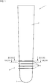
- Fig. 1 shows a liner 1 according to the invention of a first embodiment for coating over a limb stump to fix a prosthesis stem.
- the liner is designed especially as a lower leg, so it is pulled over a lower leg stump.
- the liner 1 is made of an elastic material, preferably silicone, so that it is sufficiently flexible and can adapt well to the stump geometry.
- a hollow liner body 2 which has a slightly conical shape in the example shown.
- a sealing lip section 3 is provided comprising in the example shown four radially projecting, annular circumferential sealing lips 4, which are axially spaced from each other, in the example shown by the same amount, but this is not mandatory must be the case.
- the liner 1 merges into an end-side cap section 5, which closes the liner downwards.
- the liner 1 is made of a flexible material such as silicone in particular.
- the material itself usually already has sufficient stability or strength, so that the liner 1 can be very often put on and taken off without wearing out.
- a textile reinforcing material 6 is provided, which is embedded or embedded at least on the part of the distal edge in the silicone matrix, or to which the silicone matrix is attached.
- This textile reinforcing material for example a woven or knitted fabric made of natural or synthetic fibers, has a corresponding extensibility, which is preferably given both in the axial and in the radial direction.
- Fig. 2 shows the textile reinforcing material exclusively above, ie proximal of the sealing lip portion 3, it ends a distance far from the uppermost sealing lip. 4
- Fig. 3 shows an enlarged partial view of the area III Fig. 2 under enlarged representation of the geometry of a sealing lip 4. This geometry is the same for all four sealing lips 4. Already at this point it should be noted that, of course, less or more than the four sealing lips shown can be provided. In the simplest case, only one sealing lip is provided.
- each sealing lip 4 has a trapezoidal cross-sectional shape, with two flat side surfaces 7, which converge radially outwards. Radially outward, a flat outer surface 8 is provided so that the trapezoidal shape results.
- Each side flank or side surface 7 is at an angle to the surface 9 of the liner 1, wherein in Fig. 3 the two angles are marked with ⁇ and ⁇ .
- the liner according to the invention is now characterized by a special circumferential sealing lip geometry. Because according to the invention it is provided that the height of the sealing lip, that is the extent to which the sealing lip extends radially outward, varies around the circumference, ie not, as in the prior art, the case is constant around the circumference.
- the FIGS. 4 to 6 show different sealing lip shapes in the section corresponding to the section lines IV, V and VI Fig. 1 ,
- the front of the liner 1 is displayed, ie the frontal direction.
- the liner should be worn so that this frontal area also lies on the front side of the stump, ie in the case of the lower leg stump, ie in front of the tibial or shin bone edge.
- the height of the sealing lip 4 varies continuously from a maximum value at a first circumferential position to a minimum value given at a second circumferential position.
- Fig. 1 is the first, given here maximum height value h 1 at a frontal circumferential position U 1 and shown, while the second, here minimum height value h 2 is given at an excellent second circumferential position U 2 , in the embodiment shown by 180 ° opposite to the first circumferential position U 1 is given.
- the sealing lip height decreases continuously until at the circumferential position U 2 it has the minimum, second height value h 2 .
- the height value h 1 is 6 mm, while the height value h 2 is 4 mm.
- the circumferential position U 1 is in the region of respectively in front of the tibia or shin bone edge, while the Circumferential position U 2 is positioned in the calf area.
- the area with a higher executed sealing lip is positioned in the frontal area.
- the lower leg stump If the lower leg stump is relatively slender, it shows in the frontal area a geometry that deviates significantly from a circular arc shape, as a result of the fact that in such slimmer lower leg stumps the cross-sectional geometry is increasingly defined by the bony structures, in particular the tibia.
- the frontal area is more likely to have a slightly triangular geometry or a flattening medial to the tibia. Of course, this also leads to a corresponding geometry of the over pulled liner. 1
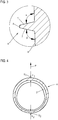
- Fig. 5 shows a further embodiment of a sealing lip geometry in a sectional view.
- the sealing lip in each case has a defined height h 1 and h 2 , that is, that the sealing lip height in each of these peripheral regions Ub 1 and Ub 2 is constant.
- a transition area Ü in which the height value of h 1 to h 2 decreases continuously.
- the peripheral region Ub 1 is again in the frontal liner region, it extends by way of example by approximately 180 °, wherein this peripheral region Ub 1 can also extend over a slightly larger or smaller angle segment.
- the constant height value h 1 is given.
- h 1 and h 2 again represent maximum and minimum values.
- a transition region Ü adjoins the dorsal liner section, in which the height value of h 1 to h 2 decreases continuously.
- the first transition region Ub 1 opposite peripheral region Ub 2 then the constant height value h 2 of the sealing lip 4 is given.
- this second circumferential region Ub 2 extends around a smaller angular segment than the first peripheral region Ub 1 , but the configuration can also be reversed, as both circumferential regions Ub 1 and Ub 2 can each rotate around an equal angular segment.
- the length of the peripheral regions Ub 1 and Ub 2 is variable, the length of the two transition regions U is inevitably variable, they may be the same or different lengths.
- any possible tilting of the stump in the prosthesis stem will ensure a permanent abutment of the or all sealing lips 4 on the prosthesis shaft inner wall.
- FIG. 6 shows a further embodiment of a sealing lip geometry in a sectional view. Comparable with the embodiment according to Fig. 5 Here are two extending to corresponding angle sections
- Peripheral areas Ub 1 and Ub 2 given, which are positioned opposite to each other. Again, the peripheral area Ub 1 is frontal and the peripheral area Ub 2 is arranged dorsally. In the peripheral area Ub 1 , a constant height value h 1 is given, which is, for example, 6 mm, as in the preceding exemplary embodiments, while a constant height value h 2 , for example 4 mm, is given in the peripheral area Ub 2 .
- a transitional region Ü provided here.
- the sealing lip height is reduced even more.
- the given in the transition regions Ü height value h 3 is smaller than the given in the second peripheral area Ub 2 height value H 2.
- Such lateral height reduction is conceivable at anatomically meaningful positions such as the sides, after usually a tilting of the lower leg stump in the prosthesis shaft to the side occurs to a lesser extent and a slightly lower sealing lip height is sufficient in this area. If, for whatever reason, an increase in the thickness of the lips is required at anatomically sensible positions, this would also be the case in the Fig. 6 described embodiment readily possible in the transition region Ü.
- the liner 1 according to the invention also has the option of varying the wall thickness of the liner body 2 in the sealing lip portion 3. Since too high a linear body wall thickness in the region of the hollow of the knee is felt to be uncomfortable by the wearer when bending the knee due to the fact that wrinkles are formed, the liner body 2 is designed to be as thin-walled as possible. On the other hand, there is the problem, in particular in the case of slender lower leg stumps with a dominant tibial edge, that areas of low soft tissue coverage are present where there may be a pressure load on the dumbbell in the sealing lip area if the limb body wall thickness is too low, which may make the limb stump sagging or cause lesions. Therefore In addition to the sealing lip height also varies the wall thickness of the liner body 2 in the sealing lip portion 3, as already in the FIGS. 4 to 6 is shown.
- Fig. 7 shows an enlarged sectional view of the liner body 2 along the line VII Fig. 1 , In turn, the frontal direction P is indicated.
- the liner body 2 can be seen to have a first liner body peripheral region Sub 1 , which is formed frontally, in which a first wall thickness H 1 of the liner body 2 is given.
- a second liner body peripheral region Sub 2 is given, which has a reduced wall thickness H 2 , wherein between the two a liner body transition region S is given, in which the liner body wall thickness decreases from the value H 1 to the value H 2 .
- the variation of the liner body wall thickness is preferably provided only in the sealing lip region 3.
- the wall thickness H 2 executed, that is, the wall thickness decreases again to a constant, low value, so for example over the knee, again in a frontal Area, not too much liner material is located, which would unnecessarily complicate the bending of the knee, or in the area of the popliteal fossa, that is in the dorsal region relatively little material and there is only a small amount of drape.
- the wall thickness variation can be maintained from the sealing lip portion; alternatively, a circumferentially uniform thin wall thickness can also be provided here.
- Fig. 8 shows a further sectional view through the liner body 2 along the line VIII - VIII and a representation of a further cross-sectional geometry of the liner body.
- the wall thickness of the liner body 2 noticeably varies.
- a first liner body peripheral region Sub 1 is at a frontal Position again given a first wall thickness value H 1 , which is already greater than that in the second Liner Eisenips Society Sub 2 , in which the lower wall thickness value H 2 is given.
- the wall thickness is increased in the liner body peripheral region Sub 1 starting from the value H 1 substantially to a wall thickness value H 3, for which purpose the LinerSystemwandung is thickened inwards so that the in Fig. 8 shows specific geometry shown.
- This thickening is effected by a continuous increase in thickness and toward the two lateral ends of the liner body peripheral region Sub 1 by a corresponding continuous decrease and a transition into the respective lateral transition region Ü, in which the wall thickness decreases continuously until the wall thickness value H 2 is reached.
- the liner body wall thickness on the left and on the right of the tibial edge is increased, that is, it is therefore thickened radially inwards.
- the in FIG. 8 described thickness increase to the value H 3 only on one side of the Tibikante.
Landscapes
- Health & Medical Sciences (AREA)
- Cardiology (AREA)
- Oral & Maxillofacial Surgery (AREA)
- Transplantation (AREA)
- Engineering & Computer Science (AREA)
- Biomedical Technology (AREA)
- Heart & Thoracic Surgery (AREA)
- Vascular Medicine (AREA)
- Life Sciences & Earth Sciences (AREA)
- Animal Behavior & Ethology (AREA)
- General Health & Medical Sciences (AREA)
- Public Health (AREA)
- Veterinary Medicine (AREA)
- Prostheses (AREA)
Description
- Die Erfindung betrifft einen Liner zum Überziehen über einen Gliedmaßenstumpf zur Fixierung eines Prothesenschafts, mit einem hohlen Linerkörper und wenigstens einer umlaufenden, seitlich vom Linerkörper abstehenden flexiblen Dichtlippe zur dichten Anlage an der Innenseite des Prothesenschafts.
- Ein solcher Liner dient dazu, eine hinreichend feste Fixierung eines Prothesenschafts an einem Gliedmaßenstumpf zu ermöglichen. Der Liner besteht aus einem hinreichend flexiblen Material, insbesondere einem Silikon, so dass er sich gut der Form des Gliedmaßenstumpfes, über den er gezogen wird, anpassen kann. Im Bereich des distalen Endes des hohlen Linerkörpers ist wenigstens eine, zumeist mehrere axial voneinander beabstandete Dichtlippen ebenfalls aus einem flexiblen Material, vornehmlich dem gleichen Material wie dem des Linerkörpers, also einem Silikon, vorgesehen. Diese Dichtlippe oder diese mehreren Dichtlippen legen sich an die Innenseite des Prothesenschafts an, wenn der mit dem Liner versehene Stumpf in den Prothesenschaft eingeführt wird. Durch das Einführen wird Luft aus dem Prothesenschaft herausgedrückt, wozu üblicherweise ein entsprechendes Ventil vorgesehen ist, das bevorzugt so im Prothesenschaft angeordnet ist, dass es sich bei arretiertem Liner distal der distalsten Dichtlippe befindet. In dieser arretierten Endstellung ist der Liner über die eine oder die mehreren Dichtlippen zum Prothesenschaft hin abgedichtet, so dass, wenn der Stumpf nebst Liner aus dem Prothesenschaft herausgezogen werden würde, ein Unterdruck im Inneren des Prothesenschafts erzeugt wird, der dieses Herausziehen verhindert. Die Funktion eines solchen Liners ist hinreichend bekannt.
- Es liegt auf der Hand, dass die Geometrie verschiedener Gliedmaßenstümpfe hochgradig unterschiedlich ist. Dies ist insbesondere im Unterschenkelbereich der Fall. Einerseits variiert der Umfang mitunter beachtlich, andererseits ergeben sich auch ausgeprägte Geometrieunterschiede im Bereich der Tibiakante, also der Schienbeinkante. Die Schienbeinkante ist bei kräftigen, dickeren Unterschenkeln weit weniger ausgeprägt als bei schlanken, dünnen Unterschenkeln, wo die Tibiakante teilweise sehr dominant den vorderen Unterschenkelbereich definiert. Die Geometrie der Querschnittsflächen weicht hier von einer üblicherweise rundlichen Geometrie ab, es ergibt sich eine eher kantigere, von der Tibiakante definierte Geometrie, die medial zur Tibikante eine Abflachung aufweist. Es hat sich nun gezeigt, dass es mitunter bei Trägern solcher Liner, deren Unterschenkel solche eine von einer runden Querschnittsfläche starke abweichende Geometrie aufweist, zu einem Ablösen der einen oder der mehreren Dichtlippen von der Innenseite des Prothesenschaftes kommt, wodurch der Unterdruck im Prothesenschaft verloren geht und der Prothesenschaft nicht mehr zuverlässig mit dem Liner verbunden ist. Dieses Ablösen ist auf die von der Ringform des Linerkörpers respektive der einen oder mehreren Dichtlippen teilweise deutlich abweichenden Geometrie des Unterschenkels im Bereich der Tibiakante zurückzuführen.
- Insbesondere beim Sitzen, wenn der Stumpf im Prothesenschaft quasi nach hinten kippt, wurde festgestellt, dass es in manchen Fällen zu einem Ablösen der einen oder mehreren Dichtlippen im vorderen Linerbereich kommt, so dass auch in solchen Situationen der Unterdruck im Prothesenschaft verloren gehen kann. Dieser Effekt kann durch eine eher kantige Geometrie im Tibiakantenbereich noch verstärkt werden.
- Der Erfindung liegt damit das Problem zugrunde, einen Liner anzugeben, der demgegenüber verbessert ist.
- Zur Lösung dieses Problems ist bei einem Liner der eingangs genannten Art erfindungsgemäß vorgesehen, dass die Höhe der Dichtlippe um ihren Umfang von einem ersten Höhenwert an eine erste Umfangsposition oder in einem ersten Umfangsbereich zu einem zweiten Höhenwert an einer zweiten Umfangsposition oder in einem zweiten Umfangsbereich variiert.
- Anders als im bisherigen Stand der Technik, bei dem wenigstens eine ringförmig umlaufende Dichtlippe um den gesamten Umfang stets eine gleichbleibende, konstante Höhe aufweist, ist erfindungsgemäß eine definierte Variation der Dichtlippenhöhe vorgesehen. Die Dichtlippenhöhe variiert zwischen einem ersten und einem zweiten, kleineren Höhenwert, wobei die beiden Höhenwerte jeweils an definierten ersten und zweiten Umfangspositionen gegeben sein können, oder in entsprechenden ersten und zweiten Umfangsbereichen. Im erst genannten Fall ist also eine Umfangsposition mit dem ersten Höhenwert und eine Umfangsposition mit dem zweiten Höhenwert vorgesehen, während im zweitgenannten Fall jeweils Umfangsbereiche vorgesehen sind, in denen ein konstanter erster Höhenwert und ein konstanter zweiter Höhenwert gegeben ist. Selbstverständlich sind auch Mischformen denkbar, das heißt, dass an einer Position ein definierter erster Höhenwert gegeben ist, von dem ausgehend die Dichtlippe in einem Umfangsbereich, in dem ein konstanter zweiter Höhenwert gegeben ist, abnimmt und ähnliches.
- Diese Höhenvariation ermöglicht es nun, die Dichtlippenhöhe so anzupassen, dass die Höhe in einem Umfangsbereich, der in der Tragstellung vorne, also im Bereich der Tibiakante positioniert ist, größer ist als in anderen Bereichen, beispielsweise an der gegenüberliegenden Linerseite. Das heißt, dass in einem bezogen auf die Tragstellung kritischen Linerbereich, wo es also zu einem Ablösen der Dichtlippe kommen kann, die Dichtlippe länger ist, so dass, selbst wenn der Stumpf im Prothesenschaft geringfügig verkippt, aufgrund der größeren Dichtlippenlänge immer noch eine dichte Anlage der Dichtlippe zum Prothesenschaft gegeben ist. Durch diese Höhenvariation um den Dichtlippenumfang wird folglich einer durch die Bewegung oder Sitzposition hervorgerufenen Verlagerung der Dichtlippe dahingehend Rechnung getragen, dass gerade in dem oder den Bereichen, wo eine Ablösung der Dichtlippe unter Verlust des Unterdrucks möglich sein kann, die Dichtlippe länger ausgeführt ist, mithin also eine dichte Anlage am Prothesenschaft auch bei einer größeren Verlagerung der Dichtlippe relativ zum Linerkörper sichergestellt ist. Durch den erfindungsgemäßen Liner ist sichergestellt, dass sich die Dichtlippe auch in unterschiedlichen Bewegungs- oder Sitzpositionen etc. nicht vom Prothesenschaft lösen kann, so dass der Unterdruck auch in diesen Situationen aufrechterhalten werden kann, auch wenn es zu einer Verlagerung des Stumpfes im Prothesenschaft kommt, respektive die Stumpfgeometrie eine ausgeprägte Tibiakante mit starker Abweichung von einer eher rundlichen Umfangsform aufweist.
- Dabei ist die erste Umfangsposition oder der erste Umfangsbereich bevorzugt gegenüberliegend zu der zweiten Umfangsposition oder dem zweiten Umfangsbereich angeordnet. Das heißt, dass die erste Umfangsposition oder der erste Umfangsbereich mit dem ersten Höhenwert der Dichtlippenhöhe frontal ausgebildet respektive vorgesehen ist, während die zweite Umfangsposition oder der zweite Umfangsbereich mit dem zweiten Höhenwert dorsal, also gegenüberliegend und quasi um 180° versetzt, vorgesehen ist. Dies ist zweckmäßig, als üblicherweise im dorsalen Bereich der Unterschenkelstumpf eine rundliche Form aufweist, die zwangsläufig nicht zu einem unbeabsichtigten, geometriebedingten Ablösen führt.
- Um ein Ablösen der Dichtlippe auch im Bereich der Abflachung, welche medial zur Tibikante verläuft, zu verhindern, ist der Bereich der größten Dichtlippenhöhe alternativ in dem abgeflachten Bereich des Unterschenkels vorgesehen.
- Bevorzugt sind am Liner mehrere axial geringfügig voneinander beabstandete Dichtlippen vorgesehen, wobei die Höhe nur einer Dichtlippe, mehrerer Dichtlippen oder aller Dichtlippen in der erfindungsgemäßen Weise variieren kann. Dabei können die ersten und zweiten Höhenwerte der unterschiedliche Höhen aufweisenden Dichtlippen gleich sein, sie können sich aber auch von Dichtlippe zu Dichtlippe unterscheiden.
- Hinsichtlich des konkreten Dichtlippendesigns respektive Höhenverlaufs sind unterschiedliche erfindungsgemäße Ausgestaltungen denkbar. Nach einer ersten Erfindungsalternative kann die Höhe ausgehend von einer den ersten Höhenwert aufweisenden ersten Umfangsposition, bevorzugt kontinuierlich oder stufenweise, zu dem an einer zweiten Umfangsposition gegebenen zweiten Höhenwert hin abnehmen. Es sind also zwei ausgezeichnete Umfangspositionen vorgesehen, die, wie bereits beschrieben, bevorzugt einander gegenüberliegend frontal und dorsal ausgebildet sind. Der erste Höhenwert stellt dabei einen Maximalwert und der zweite Höhenwert einen Minimalwert dar. Die Dichtlippenhöhe nimmt kontinuierlich vom Maximalwert um den Umfang zum Minimalwert hin ab.
- Gemäß einer Erfindungsalternative kann die Höhe in einem Umfangsbereich gleichbleibend den ersten Höhenwertwert aufweisen und anschließend, bevorzugt kontinuierlich oder stufenweise, zu dem zweiten Höhenwert hin abnehmen. Hier ist also frontal ein Maximalwert-Umfangsbereich mit konstanter Dichtlippenhöhe vorgesehen, wobei die Dichtlippenhöhe beidseits dieses Umfangsbereichs zu einer Umfangsposition, die den zweiten Höhenwert, auch hier ein Minimalwert aufweist, vorzugsweise kontinuierlich hin abnimmt. Es ist also ein Maximalwertbereich und eine Minimalwertposition vorgesehen.
- Alternativ kann die Ausgestaltung auch umgekehrt sein, nämlich dass die Höhe ausgehend von einer den ersten Höhenwert, auch hier ein Maximalwert, aufweisenden Umfangsposition, bevorzugt kontinuierlich oder stufenweise, zu dem zweiten Höhenwert, hier wieder ein Minimalwert, hin abnimmt, der in einem Umfangsbereich gleichbleibend gegeben ist. Hier ist also eine Maximalwertposition und ein Minimalwertbereich vorgesehen. Wieder nimmt die Dichtlippenhöhe von der Maximalwertposition beidseits vorzugsweise kontinuierlich ab, bis der Minimalwert erreicht ist, der im Umfangsbereich gegeben ist.
- Eine weitere Erfindungsalternative sieht vor, dass die Höhe in einem ersten Umfangsbereich gleichbleibend den ersten Höhenwert, der wieder einen Maximalwert darstellt, aufweist, dass die Höhe in einem daran anschließenden Übergangsbereich, bevorzugt kontinuierlich oder stufenweise, abnimmt, und dass die Höhe in einem daran anschließenden zweiten Umfangsbereich gleichbleibend den zweiten Höhenwert, der wieder einen Minimalwert definiert, aufweist. Hier ist also ein Maximalwertbereich und ein Minimalwertbereich gegeben. Zwischen den beiden Bereichen ist jeweils beidseits am Liner jeweils ein Übergangsbereich gegeben, innerhalb dem die Höhe bevorzugt kontinuierlich vom Maximalwertbereich zum Minimalwertbereich hin abnimmt.
- In diesem Zusammenhang ist es denkbar, dass die Höhe in einem oder in beiden Übergangsbereichen abschnittsweise kleiner ist als der im zweiten Umfangsbereich gegebene zweite Höhenwert, oder größer als der im ersten Umfangsbereich gegebene erste Höhenwert. Gemäß dieser Erfindungsausgestaltung ist quasi im lateralen Bereich oder in beiden lateralen Bereichen, also in den Abschnitten zwischen den frontalen und dorsalen Bereichen, eine gezielte Höhenreduzierung unter den zweiten Höhenwert (der in diesem Fall keinen Minimalwert darstellt) Minimalwert vorgesehen, also in anatomisch sinnvollen Bereichen. Alternativ kann lokal gesehen in diesen Bereichen auch eine geringfügige Höhenerhöhung über den ersten Höhenwert (der in diesem Fall keinen Maximalwert darstellt) hinaus erfolgen, wenn dies anatomisch zweckmäßig ist.
- Der erste Höhenwert der Dichtlippenhöhe, der wie beschrieben insbesondere im frontalen Bereich gegeben ist, sollte zwischen 4 - 8 mm, insbesondere bei 6 mm liegen, während der zweite Höhenwert, der bevorzugt gegenüberliegend im dorsalen Bereich gegeben ist, zwischen 2 - 5 mm, insbesondere bei 4 mm liegt. Die beiden Höhenwerte können beliebig gewählt werden, solange der frontale erste Höhenwert an der ersten Umfangsposition oder im ersten Umfangsbereich größer ist als der dorsale zweite Höhenwert an der zweiten Umfangsposition oder im zweiten Umfangsbereich.
- Die Dichtlippe weist gemäß einer besonders zweckmäßigen Weiterbildung der Erfindung bevorzugt eine trapezförmige Querschnittsform auf, mit zwei ebenen Seitenflächen und einer diese verbindenden ebenen Außenfläche. Eine solche Trapezform ist insbesondere in Bezug auf die Herstellung zweckmäßig, da sich eine solche Kontur auf einfache Weise in das Gießwerkzeug einbringen lässt, beispielsweise unter Verwendung eines Formfräsers oder einer Erodierelektrode. Dabei ist der Winkel, in dem die Dichtlippe an ihrem Fuß in den Linienkörper trifft, unabhängig von der Eintauchtiefe des Ausformungswerkzeugs, das die Dichtlippennut in das Gießwerkezug einbringt, was bei gebogenen oder verrundeten Dichtlippenflanken nicht gewährleistet werden kann. Ein Liner mit einer derartigen trapezförmigen Dichtlippengeometrie ist beispielsweise bereits aus
WO 97/34548 - Dabei kann der Winkel, den die beiden Außenflächen der Dichtlippen zur Oberfläche des Liners einnehmen, gleich oder unterschiedlich sein, er ist jedoch stets jeweils ungleich 90°. Das heißt, dass der Winkel, den die eine Lippenaußenflanke zur Lineroberfläche respektive Linerebene gleich dem Winkel der zweiten Lippenflanke zur Lineroberfläche oder Linerebene ist, die Dichtlippe weist quasi eine symmetrische Geometrie auf. Jedoch kann alternativ auch der eine Winkel größer als der andere sein, so dass die Dichtlippe eine asymmetrische Geometrie aufweist. Keiner der Winkel weist jedoch 90° auf.
- In Weiterbildung der Erfindung kann vorgesehen sein, dass die Wandstärke des Linerkörpers im Bereich der einen oder der mehreren Dichtlippen um den Umfang variiert, wobei die Wandstärke in dem Bereich, in dem die eine oder die mehreren Dichtlippen den ersten Höhenwert aufweisen, größer ist als in dem Bereich, in dem die eine oder die mehreren Dichtlippen den zweiten Höhenwert aufweisen. Bei der Wahl der Wandstärke des Liners ist zu berücksichtigen, dass eine zu hohe Wandstärke im dorsalen Linerkörperbereich, also im Bereich der Kniekehle, vom Träger beim Beugen des Knies aufgrund der zustande kommenden Faltenbildung als unangenehm empfunden werden kann. Andererseits sind die Dichtlippen besonders in Bereichen geringer Weichteildeckung mit ausreichend Silikon zu unterfüttern, damit im Linerkörper an diesen Stellen keine Drucküberhöhung zustande kommt, die das Entstauen des Gliedmaßenstumpfes erschweren oder Läsionen zur Folge haben können. Deshalb weist der Liner zweckmäßigerweise im Linerkörperbereich, in dem die eine oder die mehreren Dichtlippen vorgesehen sind, umlaufend unterschiedliche Wandstärken auf. Die Bereiche, in denen die Wandstärke variiert, sind nicht zwingend mit den Umfangsbereichen, in denen die Höhenvariation vorgesehen ist, identisch.
- Bevorzugt ist hierbei die Wandstärke in einer ersten Linerkörperumfangsposition oder in einem ersten Linerkörperumfangsbereich, die oder der der Umfangsposition oder dem Umfangsbereich mit der ersten Dichtlippenhöhe zugeordnet ist, größer als in einer zweiten Linerkörperumfangsposition oder in einem zweiten Linerkörperumfangsbereich, die oder der der Umfangsposition oder dem Umfangsbereich mit der zweiten Dichtlippenhöhe zugeordnet ist. Bevorzugt wird demgemäß insbesondere in dem Bereich der Tibiakante eine hohe Wandstärke des Linerkörpers ausgebildet, um dort eine hinreichende Unterfütterung mit dem weichen, flexiblen Linerkörpermaterial, also dem Silikon, zu erreichen, während im Bereich der Wade eine niedrigere Wandstärke gewählt wird. Ähnlich wie bei den Dichtlippen kann auch die Wandstärke ausgehend von einer Linerkörperumfangsposition zu einer Linerkörperumfangsposition, von einer Linerkörperumfangsposition zu einem Linerkörperumfangsbereich oder umgekehrt, oder von einem Linerkörperumfangsbereich zu einem Linerkörperumfangsbereich variieren.
- Dabei kann die Wandstärke in einem Bereich zwischen der ersten und der zweiten Linerkörperumfangsposition oder dem ersten und dem zweiten Linerkörperumfangsbereich kontinuierlich abnehmen. Das heißt, dass sich die Wanddicke von frontal nach dorsal kontinuierlich reduziert. Alternativ kann die Wandstärke in einem Bereich zwischen der ersten und der zweiten Linerkörperumfangsposition oder dem ersten und dem zweiten Linerkörperumfangsbereich ausgehend von der ersten Linerkörperumfangsposition oder vom ersten Linerkörperumfangsbereich zunehmen und zur zweiten Linerumfangsposition oder zum zweiten Linerkörperumfangsbereich hin wieder abnehmen. Das heißt, dass lateral am Linerkörper definierte zusätzliche lokale Aufdickungen, also definierte Wandstärkenvergrößerungen vorgesehen sind, was mitunter aus anatomischen Gründen bzw. einer Anpassung an die Stumpfgeometrie zweckmäßig sein kann. Diese lokale laterale Aufdickung ist insbesondere bei kleineren Linergrößen zweckmäßig. Denn insbesondere bei sehr schlanken Stümpfen wird die Stumpfform weniger durch die Weichteildeckung, sondern durch die darunter liegenden knöchernen Strukturen geprägt. Werden nun gezielt laterale Aufdickungen, also Aufdickungen links und rechts der Tibiakante vorgesehen, so kann eine angenähert kreisförmige Außenkontur des Liners erreicht werden. Alternativ kann auch nur medial der Tibikante aufgedickt werden.
- Ist im Bereich der Dichtlippen eine Wandstärkenerhöhung vorgesehen, so ist es zweckmäßig, wenn die Wandstärke des Linerkörpers proximal der einen oder der mehreren Dichtlippen, also des aufgedickten Bereichs, wieder abnimmt, so dass einerseits über dem Knie, also frontal, nicht zu viel Material vorhanden ist, was das Abbeugen des Knies unnötig erschweren würde. Auch im Bereich der Kniekehle ist eine reduzierte Wandstärke vorteilhaft, da so die Faltenbildung beim Abwinkeln minimiert wird.
- Aus Stabilitätsgründen ist es zweckmäßig, wenn der Linerkörper in dem Bereich proximal der einen oder der mehreren Dichtlippen mit einem textilen Verstärkungsmaterial versehen ist. Dieses textile Verstärkungsmaterial, beispielsweise ein Textilgewebe oder eine netzartige Textilstruktur oder dergleichen, ermöglicht eine starke Beanspruchung des Liners und reduziert die Gefahr einer Beschädigung desselben, wie beispielsweise eine vom umfänglich beschnittenen proximalen Rand des Liners ausgehende Rißeinleitung insbesondere während des Anziehens und Ausziehens.
- Dabei ist es zweckmäßig, wenn das textile Verstärkungsmaterial sowohl in axialer als auch in radialer Richtung dehnbar ist, wobei das Verstärkungsmaterial in beide Richtungen vorzugsweise im gleichen Maße dehnbar ist.
- Der Linerkörper sowie die Dichtlippen sind bevorzugt aus einem Silikon.
- Weitere Vorteile und Einzelheiten der Erfindung ergeben sich aus den im Folgenden beschriebenen Ausführungsbeispielen sowie anhand der Zeichnung. Dabei zeigen:
- Fig. 1
- eine Prinzipdarstellung eines erfindungsgemäßen Liners einer ersten Ausführungsform,
- Fig. 2
- eine Längsschnittansicht des Liners aus
Fig. 1 , - Fig. 3
- eine vergrößerte Teilansicht des Bereichs III aus
Fig. 2 , - Fig. 4
- eine Querschnittansicht des Liners aus
Fig. 1 in der Ebene IV - IV durch eine umlaufende Dichtlippe sowie den Linerkörper einer ersten Ausführungsform, - Fig. 5
- eine Querschnittansicht des Liners aus
Fig. 1 in der Ebene V - V durch eine umlaufende Dichtlippe sowie den Linerkörper einer zweiten Ausführungsform, - Fig. 6
- eine Querschnittansicht des Liners aus
Fig. 1 in der Ebene VI - VI durch eine umlaufende Dichtlippe sowie den Linerkörper einer dritten Ausführungsform, - Fig. 7
- eine Schnittansicht durch den Linerkörper einer ersten Ausführungsform in der Ebene VII - VII aus
Fig. 1 , - Fig. 8
- eine Schnittansicht durch den Linerkörper einer zweiten Ausführungsform in der Ebene VIII - VIII aus
Fig. 1 . -
Fig. 1 zeigt einen erfindungsgemäßen Liner 1 einer ersten Ausführungsform zum Überziehen über einen Gliedmaßenstumpf, um einen Prothesenschaft zu fixieren. Der Liner ist insbesondere als Unterschenkelliner ausgelegt, wird also über einen Unterschenkelstumpf gezogen. - Der Liner 1 ist aus einem elastischen Material, vorzugsweise Silikon, gefertigt, so dass er hinreichend flexibel ist und sich der Stumpfgeometrie gut anpassen kann.
- Er umfasst einen hohlen Linerkörper 2, der im gezeigten Beispiel eine leicht konische Form aufweist. Im Bereich des distalen Linerkörperendes ist ein Dichtlippenabschnitt 3 vorgesehen umfassend im gezeigten Beispiel vier radial abstehende, ringförmig umlaufende Dichtlippen 4, die axial voneinander beabstandet sind, im gezeigten Beispiel um das gleiche Maß, was jedoch nicht zwingend der Fall sein muss. Unterhalb des Dichtlippenabschnitts 3 geht der Liner 1 in einen endseitigen Kappenabschnitt 5 über, der den Liner nach unten hin abschließt.
- Wie beschrieben besteht der Liner 1 aus einem flexiblen Material wie insbesondere Silikon. Das Material selbst weist üblicherweise bereits eine hinreichende Stabilität respektive Festigkeit auf, so dass der Liner 1 sehr oft angezogen und ausgezogen werden kann, ohne zu verschleißen. Um die Verschleißfestigkeit weiter zu verbessern ist, siehe die Schnittansicht des Liners 1 in
Fig. 2 , an der Innenseite des Linerkörper 2 ein textiles Verstärkungsmaterial 6 vorgesehen, das zumindest seitens des distalen Randes in die Silikonmatrix eingebunden respektive eingebettet ist, oder an das die Silikonmatrix angebunden ist. Dieses textile Verstärkungsmaterial, beispielsweise ein Gewebe oder Gestrick aus Natur- oder Kunstfaser, weist eine entsprechende Dehnbarkeit auf, die bevorzugt sowohl in axialer als auch in radialer Richtung gegeben ist. WieFig. 2 zeigt befindet sich das textile Verstärkungsmaterial ausschließlich oberhalb, also proximal des Dichtlippenabschnitts 3, es endet ein Stück weit beabstandet von der obersten Dichtlippe 4. -
Fig. 3 zeigt eine vergrößerte Teilansicht des Bereichs III ausFig. 2 unter vergrößerter Darstellung der Geometrie einer Dichtlippe 4. Diese Geometrie ist bei allen vier Dichtlippen 4 gleich. Bereits an dieser Stelle ist darauf hinzuweisen, dass selbstverständlich auch weniger oder mehr als die gezeigten vier Dichtlippen vorgesehen sein können. Im einfachsten Fall ist nur eine Dichtlippe vorgesehen. - Wie
Fig. 3 zeigt, weist die respektive jede Dichtlippe 4 eine trapezförmige Querschnittsform auf, mit zwei ebenen Seitenflächen 7, die radial nach außen aufeinander zulaufen. Radial außen liegend ist eine ebene Außenfläche 8 vorgesehen, so dass sich die Trapezform ergibt. - Jede Seitenflanke oder Seitenfläche 7 steht unter einem Winkel zur Oberfläche 9 des Liners 1, wobei in
Fig. 3 die beiden Winkel mit α und β gekennzeichnet sind. - Die beiden Winkel können gleich sein, das heißt, dass α = β gilt, sie können aber auch ungleich sein, das heißt, dass α ≠ β ist. In jedem Fall gilt jedoch, dass α und β stets ungleich 90° sind. Das heißt, dass keine der Seitenflächen 7 senkrecht auf der Oberfläche 9 steht. Im gezeigten Beispiel beträgt jeder der beiden Winkel ca. 105°, wobei dieser Wert nur beispielhaft und variabel ist.
- Der erfindungsgemäße Liner zeichnet sich nun durch eine besondere umfangsmäßige Dichtlippengeometrie aus. Denn erfindungsgemäß ist vorgesehen, dass die Höhe der Dichtlippe, also das Maß, wie weit sich die Dichtlippe radial nach außen erstreckt, um den Umfang variiert, also nicht, wie im Stand der Technik der Fall, um den Umfang konstant ist. Die
Figuren 4 - 6 zeigen verschiedene Dichtlippenformen im Schnitt entsprechend der Schnittlinien IV, V und VI ausFig. 1 . - Mit dem Pfeil P ist in jeder Figur die Vorderseite des Liners 1 angezeigt, also die frontale Richtung. Der Liner ist so zu tragen, dass dieser frontale Bereich auch vorderseitig am Stumpf zu liegen kommt, im Falle des Unterschenkelstumpfes also vor der Tibia- oder Schienbeinkante.
- Gemäß dem Ausführungsbeispiel in
Fig. 1 variiert die Höhe der Dichtlippe 4 ausgehend von einem Maximalwert an einer ersten Umfangsposition kontinuierlich zu einem an einer zweiten Umfangsposition gegebenen Minimalwert. InFig. 1 ist der erste, hier maximale Höhenwert h1 an einer frontalen Umfangsposition U1 gegeben und dargestellt, während der zweite, hier minimale Höhenwert h2 an einer ausgezeichneten zweiten Umfangsposition U2 gegeben ist, die im gezeigten Ausführungsbeispiel um 180° gegenüberliegend zur ersten Umfangsposition U1 gegeben ist. Beidseits der ersten Umfangsposition U1 nimmt die Dichtlippenhöhe kontinuierlich ab, bis sie an der Umfangsposition U2 den minimalen, zweiten Höhenwert h2 aufweist. Beispielsweise beträgt der Höhenwert h1 6 mm, während der Höhenwert h2 4 mm beträgt. In der Tragstellung, wenn also der Liner 1 am Unterschenkelstumpf angeordnet ist, befindet sich die Umfangsposition U1 im Bereich der respektive vor der Tibia- oder Schienbeinkante, während die Umfangsposition U2 im Wadenbereich positioniert ist. Das heißt, dass folglich der Bereich mit höher ausgeführter Dichtlippe im frontalen Bereich positioniert ist. Wird nun der mit dem Liner 1 versehene Unterschenkelstumpf in den Prothesenschaft eingeführt, so gelangen die Dichtlippen 4 in Anlage an die Innenwandung des Prothesenschaftes und werden deformiert, so dass sie sich dicht an die Innenwandung anlegen und es in an sich bekannter Weise zur Erzeugung einer hinreichenden Fixierung des Prothesenschaftes kommt. Ein Herausziehen wird durch den sich hierbei ergebenden Unterdruck im Bereich distal der Dichtlippen 4 verhindert. - Ist der Unterschenkelstumpf relativ schlank, so zeigt er im frontalen Bereich eine deutlich von einer Kreisbogenform abweichenden Geometrie auf, resultierend aus dem Umstand, dass bei solchen schlankeren Unterschenkelstümpfen die Querschnittsgeometrie verstärkt durch die knöchernen Strukturen, hier insbesondere das Schienbein, definiert wird. Im frontalen Bereich ist eher eine leicht dreieckförmige Geometrie oder eine medial der Tibia liegende Abflachung gegeben. Dies führt natürlich auch zu einer entsprechenden Geometrie des darüber gezogenen Liners 1.
- Während es bei bisher bekannten Linern in solchen Fällen in bestimmten Bewegungssituationen und insbesondere im Sitzen dazu kam, dass sich aufgrund des Verkippens des Stumpfes im Prothesenschaft mitunter die Dichtanlage der Dichtlippe(n) im frontalen Bereich von der Innenwandung des Prothesenschaftes löst und es damit zu einem Verlust des Unterdrucks kommt, ist dies bei dem erfindungsgemäßen Liner 1 ausgeschlossen. Denn aufgrund der größeren Dichtlippenhöhe im frontalen Bereich wird ein etwaiges Verkippen des Stumpfes im Prothesenschaft ausgeglichen. Selbst wenn der Prothesenschaft geringfügig nach hinten kippt, wie dies beim Sitzen oft der Fall ist, bleibt die oder bleiben die Dichtlippen 4 im frontalen Bereich aufgrund ihrer größeren Höhe nach wie vor in ihrer Dichtanlage am Prothesenschaft.
-
Fig. 5 zeigt ein weiteres Ausführungsbeispiel einer Dichtlippengeometrie in einer Schnittdarstellung. Bei dieser Erfindungsausgestaltung sind zwei sich um den Umfang erstreckende Umfangsbereiche Ub1 und Ub2 ausgebildet, innerhalb welcher die Dichtlippe jeweils einen definierten Höhenwert h1 und h2 aufweist, das heißt dass die Dichtlippenhöhe in diesen Umfangsbereichen Ub1 und Ub2 jeweils konstant ist. Zwischen den beiden Umfangsbereichen Ub1 und Ub2 ist jeweils ein Übergangsbereich Ü gegeben, in dem der Höhenwert von h1 zu h2 kontinuierlich abnimmt. - Im gezeigten Ausführungsbeispiel befindet sich der Umfangsbereich Ub1 wiederum im frontalen Linerbereich, er erstreckt sich exemplarisch um ca. 180°, wobei sich dieser Umfangsbereich Ub1 auch um ein etwas größeres oder kleineres Winkelsegment erstrecken kann. Innerhalb dieses Bereichs ist der konstante Höhenwert h1 gegeben. h1 und h2 stellen wieder Maximal- und Minimalwerte dar.
- Zum dorsalen Linerabschnitt hin schließt sich nun jeweils ein Übergangsbereich Ü an, in dem der Höhenwert von h1 auf h2 kontinuierlich abnimmt. Im zweiten, dem ersten Übergangsbereich Ub1 gegenüberliegenden Umfangsbereich Ub2 ist sodann der konstante Höhenwert h2 der Dichtlippe 4 gegeben. Dieser zweite Umfangsbereich Ub2 erstreckt sich im gezeigten Beispiel um ein kleineres Winkelsegment als der erste Umfangsbereich Ub1, wobei die Ausgestaltung aber auch umgekehrt getroffen sein kann, wie beide Umfangsbereiche Ub1 und Ub2 um jeweils ein gleiches Winkelsegment umlaufen können. Wie die Länge der Umfangsbereiche Ub1 und Ub2 variabel ist, so ist zwangsläufig auch die Länge der beiden Übergangsbereiche Ü variabel, sie können gleich oder unterschiedlich lang sein.
- Von der Funktion her ergibt sich auch hier, dass aufgrund der größeren Dichtlippenhöhe H1 im frontalen Bereich bei einem etwaigen Verkippen des Stumpfes im Prothesenschaft eine dauerhafte Anlage der oder aller Dichtlippen 4 an der Prothesenschaftinnenwandung sichergestellt ist.
-
Fig. 6 zeigt schließlich eine weitere Ausführungsform einer Dichtlippengeometrie in einer Schnittdarstellung. Vergleichbar mit der Ausgestaltung gemäßFig. 5 sind auch hier zwei sich um entsprechende Winkelabschnitte erstreckende - Umfangsbereiche Ub1 und Ub2 gegeben, die einander gegenüberliegend positioniert sind. Wiederum ist der Umfangsbereich Ub1 frontal und der Umfangsbereich Ub2 dorsal angeordnet. Im Umfangsbereich Ub1 ist ein konstanter Höhenwert h1 gegeben, der wie auch bei den vorhergehenden Ausführungsbeispielen beispielsweise 6 mm beträgt, während im Umfangsbereich Ub2 ein konstanter Höhenwert h2, der beispielsweise 4 mm beträgt, gegeben ist.
- Zwischen den beiden Umfangsbereichen Ub1 und Ub2 ist beidseits, also lateral, jeweils auch hier ein Übergangsbereich Ü vorgesehen. Anders als bei der Ausgestaltung gemäß
Fig. 5 , bei der im Übergangsbereich Ü die Dichtlippenhöhe kontinuierlich von h1 auf h2 abnimmt, ist im jeweiligen Übergangsbereich Ü gemäßFig. 6 die Dichtlippenhöhe noch stärker reduziert. Der in den Übergangsbereichen Ü gegebene Höhenwert h3 ist kleiner als der im zweiten Umfangsbereich Ub2 gegebene Höhenwert h2. Eine solche laterale Höhenreduzierung ist an anatomisch sinnvollen Positionen wie beispielsweise den Seiten denkbar, nachdem üblicherweise ein Verkippen des Unterschenkelstumpfes in dem Prothesenschaft zur Seite hin in geringerem Maß vorkommt und eine etwas geringere Dichtlippenhöhe in diesen Bereich ausreichend ist. Ist aus welchen Gründen auch immer an anatomisch sinnvollen Positionen eine Dichtlippenerhöhen erforderlich sein, so wäre auch dies bei der inFig. 6 beschriebenen Ausgestaltung ohne weiteres im Übergangsbereich Ü möglich. - Wie bereits den
Figuren 4 - 6 dem Grunde nach zu entnehmen ist, besteht beim erfindungsgemäßen Liner 1 auch die Möglichkeit, die Wanddicke des Linerkörpers 2 im Dichtlippenabschnitt 3 zu variieren. Da eine zu hohe Linerkörperwandstärke im Bereich der Kniekehle vom Träger beim Beugen des Knies aufgrund der zustande kommenden Faltenbildung als unangenehm empfunden wird, wird der Linerkörper 2 möglichst dünnwandig ausgelegt. Andererseits besteht insbesondere bei schlanken Unterschenkelstümpfen mit dominanter Tibiakante das Problem, dass Bereiche geringer Weichteildeckung gegeben sind, an denen es im Dichtlippenbereich bei zu geringer Linerkörperwandstärke zu einer Druckbelastung des Stumpfes kommen kann, was das Entstauen des Gliedmaßenstumpfes erschweren oder Läsionen zur Folge haben kann. Daher variiert neben der Dichtlippenhöhe auch die Wandstärke des Linerkörpers 2 im Dichtlippenabschnitt 3, wie dies bereits in denFiguren 4 - 6 dargestellt ist. -
Fig. 7 zeigt eine vergrößerte Schnittansicht des Linerkörpers 2 entlang der Linie VII ausFig. 1 . Angegeben ist wiederum die Frontalrichtung P. Ersichtlich weist der Linerkörper 2 einen ersten Linerkörperumfangsbereich Sub1 auf, der frontal ausgebildet ist, in dem eine erste Wandstärke H1 des Linerkörpers 2 gegeben ist. Des Weiteren ist ein zweiter Linerkörperumfangsbereich Sub2 gegeben, der eine reduzierte Wandstärke H2 aufweist, wobei zwischen beiden ein Linerkörperübergangsbereich Sü gegeben ist, in dem die Linerkörperwandstärke vom Wert H1 auf den Wert H2 abnimmt. Dadurch, dass die Linerkörperwandstärke im frontalen Bereich, also in dem Bereich, in dem das Schienbein umgriffen ist, stärker ausgelegt ist, ist folglich dieser druckempfindliche Bereich stärker unterfüttert, mithin also der druckempfindliche Schienbeinbereich über den dämpfenden Linerkörper 2 besser geschützt. - Die Variation der Linerkörperwandstärke ist wie beschrieben bevorzugt nur im Dichtlippenbereich 3 vorgesehen. Insbesondere oberhalb respektive proximal des Dichtlippenbereichs 3 ist der Linerkörper 2 mit einer konstanten Wandstärke, beispielsweise der Wandstärke H2, ausgeführt, das heißt, dass die Wandstärke wieder auf einen konstanten, geringen Wert abnimmt, damit sich beispielsweise über dem Knie, wiederum in einem frontalen Bereich, nicht zu viel Linerkörpermaterial befindet, was das Abbeugen des Knies unnötig erschweren würde, bzw. im Bereich der Kniekehle, also im dorsalen Bereich relativ wenig Material befindet und es nur in geringem Maß zu einem Faltenwurf kommt. Zum distalen Linerende hin kann die Wandstärkenvariation aus dem Dichtlippenabschnitt beibehalten werden, alternativ kann auch hier eine umfänglich gleichmäßige dünne Wandstärke vorgesehen sein.
-
Fig. 8 zeigt eine weitere Schnittansicht durch den Linerkörper 2 entlang der Linie VIII - VIII und eine Darstellung einer weiteren Querschnittsgeometrie des Linerkörpers. Auch hier variiert ersichtlich die Wandstärke des Linerkörpers 2 beachtlich. In einem ersten Linerkörperumfangsbereich Sub1 ist an einer frontalen Position wiederum ein erster Wandstärkenwert H1 gegeben, der bereits größer ist als der im zweiten Linerkörperumfangsbereich Sub2, in dem der niedrigere Wandstärkenwert H2 gegeben ist. Um sich jedoch im frontalen Bereich noch besser der mitunter stark von einer rundlichen Form abweichenden Unterschenkelgeometrie anpassen zu können, vergrößert sich die Wandstärke im Linerkörperumfangsbereich Sub1 ausgehend vom Wert H1 deutlich auf einen Wandstärkenwert H3, wobei hierzu die Linerkörperwandung nach innen hin aufgedickt wird, so dass sich die inFig. 8 gezeigte spezifische Geometrie ergibt. Diese Aufdickung erfolgt durch einen kontinuierlichen Dickenzuwachs und zu den beiden seitlichen Enden des Linerkörperumfangsbereichs Sub1 hin durch eine entsprechende kontinuierliche Abnahme und einen Übergang in den jeweiligen lateralen Übergangsbereich Ü, in dem die Wandstärke kontinuierlich abnimmt, bis der Wandstärkenwert H2 erreicht ist. Das heißt, dass bei dieser Ausgestaltung des erfindungsgemäßen Liners die Linerkörperwandstärke links und rechts der Tibiakante erhöht ist, mithin also radial nach innen hin aufgedickt ist. Alternativ ist es auch denkbar, dass die inFigur 8 beschriebene Dickenerhöhung auf den Wert H3 nur einseitig der Tibikante erfolgt.
Claims (16)
- Liner zum Überziehen über einen Gliedmaßenstumpf zur Fixierung eines Prothesenschafts, mit einem hohlen Linerkörper und wenigstens einer umlaufenden, seitlich vom Linerkörper abstehenden flexiblen Dichtlippe zur dichten Anlage an der Innenseite des Prothesenschafts, dadurch gekennzeichnet, dass die Höhe der Dichtlippe (4) um ihren Umfang von einem ersten Höhenwert (h1) an einer ersten Umfangsposition (U1) oder in einem ersten Umfangsbereich (Ub1) zu einem niedrigeren zweiten Höhenwert (h2) an einer zweiten Umfangsposition (U2) oder in einem zweiten Umfangsbereich (Ub2) variiert.
- Liner nach Anspruch 1, dadurch gekennzeichnet, dass die erste Umfangsposition (U1) oder der erste Umfangsbereich (Ub1) und die zweite Umfangsposition (U2) oder der zweite Umfangsbereich (Ub2) einander gegenüber liegen.
- Liner nach Anspruch 1 oder 2, dadurch gekennzeichnet, dass mehrere Dichtlippen (4) vorgesehen sind, wobei die Höhe nur einer, mehrerer oder aller Dichtlippen (4) variiert.
- Liner nach einem der vorangehenden Ansprüche, dadurch gekennzeichnet, dass die Höhe ausgehend von einer den ersten Höhenwert (h1) aufweisenden ersten Umfangsposition (U1) zu dem an einer zweiten Umfangsposition (U2) gegebenen zweiten Höhenwert (h2) abnimmt.
- Liner nach einem der Ansprüche 1 bis 3, dadurch gekennzeichnet, dass die Höhe in einem Umfangsbereich (Ub1) den ersten Höhenwert (h1) aufweist und anschließend zu dem zweiten Höhenwert (h2) abnimmt.
- Liner nach einem der Ansprüche 1 bis 3, dadurch gekennzeichnet, dass die Höhe in einem ersten Umfangsbereich (Ub1) den ersten Höhenwert (h1) aufweist, dass die Höhe in einem daran anschließenden Übergangsbereich (Ü) abnimmt, und dass die Höhe in dem daran anschließenden zweiten Umfangsbereich (Ub2) den zweiten Höhenwert (h2) aufweist.
- Liner nach Anspruch 6, dadurch gekennzeichnet, dass die Höhe im Übergangsbereich (Ü) abschnittsweise kleiner ist als der im zweiten Umfangsbereich (Ub2) gegebene zweite Höhenwert (h2) oder größer als der im ersten Umfangsbereich (Ub1) gegebene erste Höhenwert (h2).
- Liner nach einem der Ansprüche 1 bis 3, dadurch gekennzeichnet, dass die Höhe ausgehend von einer den ersten Höhenwert (h1) aufweisenden Umfangsposition (U1) zu dem zweiten Höhenwert (h2) abnimmt, der in einem Umfangsbereich (Ub2) gegeben ist.
- Liner nach einem der vorangehenden Ansprüche, dadurch gekennzeichnet, dass der erste Höhenwert (h1) zwischen 4 - 8 mm, insbesondere 6 mm und der zweite Höhenwert (h2) zwischen 2 - 5 mm, insbesondere 4 mm beträgt.
- Liner nach einem der vorangehenden Ansprüche, dadurch gekennzeichnet, dass die Dichtlippe (4) eine trapezförmige Querschnittsform aufweist, mit zwei ebenen Seitenflächen (7) und einer diese verbindenden ebenen Außenfläche (8).
- Liner nach Anspruch 10, dadurch gekennzeichnet, dass der Winkel (α, β), den die beiden Seitenflächen (7) zur Oberfläche (9) des Liners (1) einnehmen, gleich oder unterschiedlich ist, jedoch stets ungleich 90° ist.
- Liner nach einem der vorangehenden Ansprüche, dadurch gekennzeichnet, dass die Wandstärke des Linerkörpers (2) im Bereich der einen oder der mehreren Dichtlippen (4) um den Umfang variiert, wobei die Wandstärke in dem Bereich, in dem die eine oder die mehreren Dichtlippe dem ersten Höhenwert (h1) aufweisen, größer ist als in dem Bereich, in dem die eine oder die mehreren Dichtlippen den zweiten Höhenwert (h2) aufweisen.
- Liner nach Anspruch 12, dadurch gekennzeichnet, dass die Wandstärke in einer ersten Linerkörperumfangsposition oder in einem ersten Linerkörperumfangsbereich (Sub1), die oder der der Umfangsposition (U1) oder dem Umfangsbereich (Ub1) mit der den ersten Höhenwert aufweisenden Dichtlippenhöhe zugeordnet ist, größer ist als in einer zweiten Linerkörperumfangsposition oder in einem zweiten Linerkörperumfangsbereich (Sub2), die oder der der Umfangsposition (U2) oder dem Umfangsbereich (Ub2) mit der den zweiten Höhenwert aufweisenden Dichtlippenhöhe zugeordnet ist.
- Liner nach Anspruch 13, dadurch gekennzeichnet, dass die Wandstärke zumindest in einem Bereich zwischen der ersten und der zweiten Linerkörperumfangsposition oder dem ersten und dem zweiten Linerkörperumfangsbereich (Sub1, Sub2) abnimmt, oder dass die Wandstärke zumindest in einem Bereich zwischen der ersten Linerkörperumfangsposition und der zweiten Linerkörperumfangsposition oder dem ersten und dem zweiten Linerkörperumfangsbereich (Sub1, Sub2) ausgehend von der ersten Linerkörperumfangsposition oder vom ersten Linerkörperumfangsbereich (Sub1) zunimmt und zur zweiten Linerkörperumfangsposition oder zum zweiten Linerkörperumfangsbereich (Sub2) hin abnimmt.
- Liner nach einem der Ansprüche 12 bis 14, dadurch gekennzeichnet, dass die Wandstärke des Linerkörpers (2) proximal der einen oder der mehreren Dichtlippen (4) abnimmt.
- Liner nach einem der vorangehenden Ansprüche, dadurch gekennzeichnet, dass der Linerkörper (2) in dem Bereich proximal der einen oder der mehreren Dichtlippen (4) mit einem, vorzugsweise sowohl in axialer als auch radialer Richtung dehnbaren, textilen Verstärkungsmaterial (6) versehen ist.
Priority Applications (6)
| Application Number | Priority Date | Filing Date | Title |
|---|---|---|---|
| EP16166902.3A EP3238667B1 (de) | 2016-04-25 | 2016-04-25 | Liner zum überziehen über einen gliedmassenstumpf |
| PCT/US2017/029063 WO2017189398A1 (en) | 2016-04-25 | 2017-04-24 | Prosthetic liner |
| US15/494,968 US10159585B2 (en) | 2016-04-25 | 2017-04-24 | Prosthetic liner |
| US16/224,007 US11123203B2 (en) | 2016-04-25 | 2018-12-18 | Prosthetic liner |
| US17/471,579 US12167974B2 (en) | 2016-04-25 | 2021-09-10 | Prosthetic liner |
| US18/941,395 US20250064607A1 (en) | 2016-04-25 | 2024-11-08 | Prosthetic liner |
Applications Claiming Priority (1)
| Application Number | Priority Date | Filing Date | Title |
|---|---|---|---|
| EP16166902.3A EP3238667B1 (de) | 2016-04-25 | 2016-04-25 | Liner zum überziehen über einen gliedmassenstumpf |
Publications (2)
| Publication Number | Publication Date |
|---|---|
| EP3238667A1 EP3238667A1 (de) | 2017-11-01 |
| EP3238667B1 true EP3238667B1 (de) | 2018-10-10 |
Family
ID=55809013
Family Applications (1)
| Application Number | Title | Priority Date | Filing Date |
|---|---|---|---|
| EP16166902.3A Active EP3238667B1 (de) | 2016-04-25 | 2016-04-25 | Liner zum überziehen über einen gliedmassenstumpf |
Country Status (3)
| Country | Link |
|---|---|
| US (4) | US10159585B2 (de) |
| EP (1) | EP3238667B1 (de) |
| WO (1) | WO2017189398A1 (de) |
Families Citing this family (18)
| Publication number | Priority date | Publication date | Assignee | Title |
|---|---|---|---|---|
| US8034120B2 (en) | 2002-12-20 | 2011-10-11 | Ossur Hf | Suspension liner system with seal |
| US11523917B2 (en) | 2002-12-20 | 2022-12-13 | Ossur Hf | Suspension liner system with seal |
| US10322016B2 (en) | 2002-12-20 | 2019-06-18 | Ossur Iceland Ehf | Adjustable seal system, seal component and method for using the same |
| US10842653B2 (en) | 2007-09-19 | 2020-11-24 | Ability Dynamics, Llc | Vacuum system for a prosthetic foot |
| US8956422B2 (en) | 2011-08-22 | 2015-02-17 | Ossur Hf | Suspension liner with seal component |
| WO2017066038A1 (en) | 2015-10-15 | 2017-04-20 | Ossur Iceland Ehf | Adjustable seal system |
| EP3238667B1 (de) * | 2016-04-25 | 2018-10-10 | Össur Iceland EHF | Liner zum überziehen über einen gliedmassenstumpf |
| US11179252B2 (en) * | 2017-09-05 | 2021-11-23 | Alps South Europe, S.R.O. | Prosthetic liner with external fabric seal |
| US11224526B2 (en) * | 2018-09-04 | 2022-01-18 | Alps South Europe S.R.O. | Prosthetic liner with external fabric seal |
| WO2019089877A1 (en) | 2017-11-01 | 2019-05-09 | Ossur Iceland Ehf | Prosthetic socket system |
| EP3716919B1 (de) | 2017-11-28 | 2021-11-03 | Ossur Iceland EHF | Einstellbares dichtungssystem und eine dichtungskomponte zwischen einem residuellen glieden und eine prothesenpfannen |
| DE102017129930B4 (de) * | 2017-12-14 | 2019-07-04 | Ottobock Se & Co. Kgaa | Prothesenschaftsystem |
| US11918493B2 (en) | 2018-11-09 | 2024-03-05 | Northwestern University | Prosthetic liner apparatus for improved suspension |
| CN109549764B (zh) * | 2019-01-16 | 2019-10-11 | 西安交通大学 | 一种用于下肢假肢的接受腔的制备方法 |
| DE102019114461B3 (de) * | 2019-05-29 | 2020-11-12 | Ottobock Se & Co. Kgaa | Verfahren zum Herstellen eines Prothesenliners und System aus Prothesenliner und Prothesenschaft |
| US11324612B2 (en) * | 2019-09-20 | 2022-05-10 | United States Government As Represented By The Department Of Veterans Affairs | Breathable residual-limb socket system |
| EP3995114A1 (de) | 2020-11-08 | 2022-05-11 | Martin Rockstroh | Prothesenliner |
| WO2024163345A1 (en) * | 2023-01-30 | 2024-08-08 | Ossur Iceland Ehf | Brim for prosthetic socket |
Family Cites Families (176)
| Publication number | Priority date | Publication date | Assignee | Title |
|---|---|---|---|---|
| DE544446C (de) | 1932-02-19 | Axel Holmstroem | AEtzmaschine | |
| US980457A (en) | 1910-01-13 | 1911-01-03 | Justin Kay Toles | Artificial limb. |
| US1398824A (en) | 1921-03-01 | 1921-11-29 | Abrams Joseph | Artificial-limb socket |
| GB267988A (en) | 1925-09-18 | 1927-03-18 | Charles Albert Blatchford | Improvements in or connected with artificial limbs |
| GB263377A (en) | 1926-04-21 | 1926-12-30 | Thomas Bryant Smith | Improvements in or relating to artificial limb sockets |
| DE484363C (de) | 1928-05-22 | 1929-10-14 | Eisenwerk | An- und Ablegevorrichtung fuer Tiegeldruckpressen |
| US1893853A (en) | 1931-12-15 | 1933-01-10 | Amos E Tullis | Artificial limb |
| DE745981C (de) | 1940-09-21 | 1944-05-22 | Alois Geisen | Kuenstliches Bein mit einer durch Saugwirkung auf dem Beinstumpf zu befestigenden Huelse |
| US2325656A (en) | 1940-11-28 | 1943-08-03 | United Shoe Machinery Corp | Reinforcing shoe parts |
| US2464443A (en) | 1947-11-17 | 1949-03-15 | Charles V Ganoe | Prosthetic limb socket for amputees |
| US2530285A (en) | 1947-12-11 | 1950-11-14 | John G Catranis | Artificial leg |
| US2533404A (en) | 1948-08-13 | 1950-12-12 | Sharp Oscar | Artificial limb and valve therefor |
| DE813190C (de) | 1948-10-02 | 1951-09-10 | Franz Clouth | Saugprothese |
| BE505683A (de) | 1950-09-19 | |||
| US2689351A (en) | 1951-10-06 | 1954-09-21 | Frank A Schindler | Method of forming stump sockets |
| US2671225A (en) | 1951-11-05 | 1954-03-09 | Bardach Schoene Company Inc | Artificial limb stump socket |
| BE551068A (de) | 1955-09-16 | |||
| US2808593A (en) | 1956-02-07 | 1957-10-08 | Andersen Algot | Artificial limbs |
| DE1795809U (de) | 1958-08-23 | 1959-09-17 | Hildegard Seitz | Orthopaedische bein- oder armprothese. |
| US3393407A (en) | 1965-12-16 | 1968-07-23 | Edward J. Kandel | Artificial limb with end-bearing socket and method of making |
| US3587572A (en) | 1968-07-17 | 1971-06-28 | Michael Evans | Knee brace |
| DE2060239C3 (de) | 1970-12-08 | 1974-05-09 | Surerus, Walter, Dr.Med., 7016 Gerlingen | Prothesenschaft mit ringförmiger Stützeinlage, insbesondere für Beinprothesen |
| US3671980A (en) | 1971-02-19 | 1972-06-27 | Lincoln F Baird | Fluid pressure clamp for prosthetic appliance |
| DE2127269A1 (de) | 1971-06-02 | 1972-12-14 | Helfrecht, Manfred, 8591 Poppenreuth | Einlage fur Kunstgheder |
| US3947897A (en) | 1975-03-17 | 1976-04-06 | Owens Lester J | Apparatus for connecting a prosthesis to a bone |
| DE2540138C3 (de) | 1975-09-09 | 1978-03-02 | Walter Dr.Med. 7016 Gerlingen Surerus | Ringförmige Stützeinlage für einen Prothesenschaft |
| DE2544446C3 (de) | 1975-10-04 | 1979-12-20 | Willy Dipl.-Ing. 6602 Dudweiler Meyer | Prothese für einen Unterschenkel oder Unterarm |
| SE410271B (sv) | 1976-04-28 | 1979-10-08 | Landstingens Inkopscentral | Protes for amputerade underben med ingaende mellanlegg |
| FR2420335A1 (fr) | 1978-03-21 | 1979-10-19 | Proteor Sa | Dispositif d'adaptation pour appareils orthopediques, procede pour sa fabrication et son application a la realisation d'emboitures de protheses de membres |
| US4215679A (en) | 1978-09-06 | 1980-08-05 | Rustin Jesse L | Circulation assist device for body extremities |
| US4347204A (en) | 1978-12-19 | 1982-08-31 | Olympus Optical Co., Ltd. | Flexible tube and method of manufacturing same |
| US4311317A (en) | 1979-08-20 | 1982-01-19 | Bartels Harold U | Lip and radial seal |
| AT369978B (de) | 1980-02-19 | 1983-02-25 | Ipos Gmbh & Co Kg | Verfahren zur herstellung von prothesenschaeften und hiernach hergestellter prothesenschaft |
| GB2069847B (en) | 1980-02-22 | 1985-01-23 | Blatchford & Sons Ltd | Artificial limb |
| US4319413A (en) | 1980-04-11 | 1982-03-16 | Pruf-und Forschungsinstitut fur die Schuhherstellung | Seam construction, particularly for heel portions of shoes and method of effecting the same |
| GB2087727B (en) | 1980-10-14 | 1984-01-25 | Steeper Hugh Ltd | Manufacture of a prosthetics socket |
| US4474573A (en) | 1982-02-24 | 1984-10-02 | Detty Garnett E | Knee sleeve |
| DE3221920A1 (de) | 1982-06-11 | 1983-04-07 | Surerus, Walter, Dr., 7016 Gerlingen | Schaft einer prothese |
| FR2539616A1 (fr) | 1983-01-25 | 1984-07-27 | Renaissance Sanitaire | Emboiture souple utilisee pour la prothetisation d'un ampute femoral |
| US4635626A (en) | 1984-11-16 | 1987-01-13 | Max Lerman | Prosthetic stockings |
| US4738249A (en) | 1985-03-01 | 1988-04-19 | The Procter & Gamble Company | Method and apparatus for augmenting blood circulation |
| DE3508919A1 (de) | 1985-03-13 | 1986-09-18 | Surerus, Walter, Dr.Med., 7016 Gerlingen | Schaft einer prothese |
| SE454943B (sv) | 1986-06-26 | 1988-06-13 | Ossur Hf | Hylselement, speciellt for amputationsstump |
| JP2637076B2 (ja) | 1986-07-21 | 1997-08-06 | 三井石油化学工業 株式会社 | プロピレンブロツク共重合体の製法 |
| ES2157911T3 (es) | 1987-02-02 | 2001-09-01 | Fina Technology | Procedimiento para aumentar la eficacia de un catalizador prepolimerizado. |
| US5122583A (en) | 1987-02-02 | 1992-06-16 | Fina Technology, Inc. | Efficiency of a pre-polymerized catalyst |
| US4767735A (en) | 1987-02-02 | 1988-08-30 | Cosden Technology, Inc. | Catalyst pretreatment process |
| GB8802933D0 (en) | 1988-02-09 | 1988-03-09 | Porvair Ltd | Porelle/stretchable fabric composite & socks therefrom |
| US5007937A (en) | 1988-03-31 | 1991-04-16 | New York University Medical Center | Structure for enhanced retention of artificial limbs and method of fabrication |
| US4908037A (en) | 1988-09-16 | 1990-03-13 | Ross Michael R | Suspension prosthetic sleeve for rigorous activity |
| US4885828A (en) | 1988-11-14 | 1989-12-12 | Lear Siegler Seating Corp. | Method and apparatus for positioning fabric covers on a foam cushion |
| US5571208A (en) | 1990-07-13 | 1996-11-05 | Caspers; Carl A. | Reinforced prosthetic polyurethane hypobaric sleeve |
| US5376129A (en) | 1990-12-04 | 1994-12-27 | Board Of Regents, The University Of Texas System | Method and apparatus for making prosthetic socket preforms, prosthetic sockets, and socket attachment component |
| US5108456A (en) * | 1991-01-28 | 1992-04-28 | Coonan Iii Thomas J | Prosthetic appliance |
| US5139523A (en) | 1991-07-12 | 1992-08-18 | Paton Matthew T | Artificial limb socket apparatus |
| US5163965A (en) | 1991-07-29 | 1992-11-17 | Becker Orthopedic Appliance Company | Prosthetic attachment device and method |
| US5169161A (en) | 1991-09-19 | 1992-12-08 | Hail Mary Rubber Co., Inc. | Symmetrical gasket for pipe joints |
| US5387245A (en) | 1991-12-23 | 1995-02-07 | Fay; John N. | Inflatable prosthesis liner |
| JPH0623406A (ja) | 1992-07-08 | 1994-02-01 | Kawasaki Steel Corp | 鋼片の連続熱間圧延方法 |
| US5226918A (en) | 1992-07-13 | 1993-07-13 | Howard Silagy | Prosthesis with adjustable fitting clearance |
| US5314496A (en) | 1992-12-31 | 1994-05-24 | Harris Bertram H | Stump sock arrangement |
| US5376131A (en) | 1993-07-01 | 1994-12-27 | Manhasset Orthotics And Prosthetics, Ltd. | Suction socket for artificial limb |
| JP3984304B2 (ja) | 1993-08-18 | 2007-10-03 | 三井化学株式会社 | オレフィン重合用触媒、これを用いるプロピレン系重合体の製造方法 |
| JPH0822295B2 (ja) | 1993-12-03 | 1996-03-06 | 株式会社奈良義肢 | 義足または義手の装着構造 |
| KR0150433B1 (ko) | 1994-03-18 | 1998-10-15 | 발레 메이커즈, 인코포레이티드 | 분리형 구두창 및 중간부분 보강부로 이루어진 신발 |
| DE9419208U1 (de) | 1994-11-30 | 1995-01-26 | Carstens, Felix, 67433 Neustadt | Künstliches Glied |
| US5728167A (en) | 1995-01-11 | 1998-03-17 | Lohmann; Klaus H. | Prosthetic sock for reducing movement between residual limb and prosthesis |
| US5593454A (en) | 1995-01-12 | 1997-01-14 | Helmy; Nashat N. | Artificial limb mounting apparatus |
| US5571209A (en) | 1995-01-27 | 1996-11-05 | Flo-Tech Orthotic & Prosthetic Systems, Inc. | Post-operative protective prosthesis |
| US5830237A (en) | 1996-03-05 | 1998-11-03 | Ohio Willow Wood Company | Gel and cushioning devices |
| US5735906A (en) | 1995-07-26 | 1998-04-07 | Caspers; Carl A. | Hypobarically-controlled artificial limb with detents for amputees |
| US5549709A (en) | 1995-07-26 | 1996-08-27 | Caspers; Carl A. | Hypobarically-Controlled artificial limb for amputees |
| US5702489A (en) | 1995-08-18 | 1997-12-30 | Materials Engineering And Development, Inc. | Valve assembly for a prosthetic limb |
| US6287345B1 (en) | 1995-08-18 | 2001-09-11 | The Ohio Willow Wood Company | Valve assembly for a prosthetic limb |
| ES2152353T3 (es) | 1995-09-08 | 2001-02-01 | Bock Orthopaed Ind | Protesis de pierna. |
| US5658353A (en) | 1995-10-31 | 1997-08-19 | Layton; Harry W. | Method for donning or doffing an artificial limb |
| EP0803343B1 (de) | 1995-11-09 | 2005-09-07 | Ashimori Industry Co., Ltd. | Auskleidung von leitungen und verfahren zu deren herstellung |
| US5718925A (en) | 1995-11-15 | 1998-02-17 | Ossur Hf. | Apparatus for making a prosthesis socket |
| US5888216A (en) | 1996-03-18 | 1999-03-30 | Haberman; Louis J. | Prosthesis liner for below-knee amputees |
| US6964688B1 (en) | 1996-07-31 | 2005-11-15 | Ohio Willow Wood Company | Tube sock-shaped covering |
| CA2260801A1 (en) | 1996-07-31 | 1998-02-05 | Ohio Willow Wood Company | Gel and cushioning devices |
| US6171431B1 (en) | 1996-08-27 | 2001-01-09 | Joseph E. Gallagher, Jr. | Welded fabric seams with inner and outer tabs |
| JP2740503B2 (ja) | 1996-08-28 | 1998-04-15 | 三井化学株式会社 | α−オレフインの重合方法 |
| US5728168A (en) | 1996-10-29 | 1998-03-17 | Alps South Corporation | Elastomer reinforcement of an elastomer interface membr for residual limb of an amputee |
| US5888230A (en) | 1997-04-01 | 1999-03-30 | Helmy; Nashat N. | Modular liner for limb stump prosthesis |
| US6918936B2 (en) | 1997-04-29 | 2005-07-19 | Kennet Hellberg | Thermoplastic liner blank |
| US5980577A (en) | 1997-05-01 | 1999-11-09 | Radis; Vasilis | Protective item supporting an appendage |
| US6136039A (en) | 1997-05-06 | 2000-10-24 | Ossur Hf | Dual durometer silicone liner for prosthesis |
| CA2289027A1 (en) | 1998-03-23 | 1999-09-30 | Montell Technology Company B.V. | Prepolymerized catalyst components for the polymerization of olefins |
| US6149691A (en) | 1998-06-26 | 2000-11-21 | Fay; John N. | Self-inflating socket having encased gel |
| US6368357B1 (en) | 1998-10-16 | 2002-04-09 | Aircast, Inc. | Therapeutic device for amputees |
| US6361568B1 (en) | 1999-02-09 | 2002-03-26 | Alps South Corporation | Prosthetic sleeve with air outlet valve |
| EP1204390B1 (de) | 1999-03-01 | 2004-08-11 | Ossur HF | Mehrteilige prothetische oder orthopädische Manschette mit unterschiedlicher Elastizität |
| US7922775B2 (en) | 1999-06-03 | 2011-04-12 | Otto Bock Healthcare Lp | Pulsating pressure chamber and method for fluid management |
| US20040098136A1 (en) | 1999-06-03 | 2004-05-20 | Caspers Carl A. | Socket liner for artificial limb with permanent attachment to socket |
| US6645253B2 (en) | 1999-06-03 | 2003-11-11 | Carl A. Caspers | Vacuum pump and shock absorber for artificial limb |
| US6554868B1 (en) | 1999-06-03 | 2003-04-29 | Carl A. Caspers | Vacuum pump and shock absorber for artificial limb |
| US6726726B2 (en) | 1999-06-03 | 2004-04-27 | Otto Bock Healthcare Lp | Vacuum apparatus and method for managing residual limb volume in an artificial limb |
| US6508842B1 (en) | 1999-06-03 | 2003-01-21 | Barbara J. Caspers | Socket liner for artificial limb |
| WO2000074611A2 (en) | 1999-06-03 | 2000-12-14 | Caspers-Schneider Technologies,Inc. | Hypobarically-controlled socket for artificial limb |
| US20010016781A1 (en) | 1999-06-03 | 2001-08-23 | Caspers Carl A. | Osmotic membrane and vacuum system for artificial limb |
| US6926742B2 (en) | 1999-06-03 | 2005-08-09 | Otto Bock Healthcare Lp | Plate/socket attachment for artificial limb vacuum pump |
| US6231617B1 (en) | 1999-07-14 | 2001-05-15 | John N. Fay | Prosthetic liner having longitudinal inelasticity |
| JP4177937B2 (ja) | 1999-08-18 | 2008-11-05 | 日本ポリプロ株式会社 | α−オレフィン重合用触媒および重合方法 |
| US6273918B1 (en) | 1999-08-26 | 2001-08-14 | Jason R. Yuhasz | Magnetic detachment system for prosthetics |
| CN1208034C (zh) | 2000-03-14 | 2005-06-29 | 奥苏尔公司 | 制造假体抽吸式衬套的方法 |
| KR20030011075A (ko) | 2000-03-14 | 2003-02-06 | 오서 에이치에프 | 보철 응용에 유용한 복합 탄성 재료 및 그것으로 제조된흡인 라이너 |
| US6485776B2 (en) | 2000-03-15 | 2002-11-26 | Ossur Hf | Apparatus and process for making prosthetic suction sleeve |
| US6585774B2 (en) | 2000-04-25 | 2003-07-01 | Simbex, Llc | Dynamic variable geometry fitting system for use with a body appliance |
| AU2001277992A1 (en) | 2000-09-27 | 2002-04-08 | Caspers-Schneider Technologies, Inc., D/B/A Tec Interface Systems | Socket liner for artificial limb |
| AU2002211218A1 (en) | 2000-10-04 | 2002-04-15 | Ossur Hf | Prosthetic socket and socket component assembly |
| NO313119B1 (no) | 2000-10-18 | 2002-08-12 | Dag Vilnes | Rammekonstruksjon for plane konstruksjoner |
| US20020183859A1 (en) | 2001-06-04 | 2002-12-05 | Houser Guy M. | Socket interface sleeve for a prosthetic device |
| FR2828093B1 (fr) | 2001-08-06 | 2004-06-25 | Renaissance Sanitaire | Emboiture souple pour la prothetisation d'une personne amputee du membre superieur |
| DE10142492A1 (de) | 2001-08-30 | 2003-04-03 | Carstens Orthopaedie Und Mediz | Prothesenschaft mit Dichtung |
| DE10142491B4 (de) | 2001-08-30 | 2004-10-07 | össur h.f. | Dichtanordnung mit Lippen für einen Prothesenschaft |
| DE10164892B4 (de) | 2001-11-05 | 2009-08-27 | össur h.f. | Strumpfförmiger Liner bzw. Liner zur Verwendung mit einem becherförmigen Prothesenschaft |
| US20030181989A1 (en) | 2002-03-19 | 2003-09-25 | Ssl Americas, Inc. | Cushioned liner and use with prosthetic devices |
| US6852269B2 (en) | 2002-03-19 | 2005-02-08 | Silipos, Inc. | Process for applying a cushion material to an article |
| US6544292B1 (en) | 2002-04-08 | 2003-04-08 | Aldo A. Laghi | Prosthetic liner with integral air expulsion valve |
| AU2003233682A1 (en) | 2002-05-23 | 2003-12-12 | Otto Bock Healthcare Lp | Pulsating pressure chamber and method for enhanced blood flow |
| US6929125B1 (en) | 2002-07-25 | 2005-08-16 | Foam Technologies, Inc. | Watertight protective carrying case |
| KR100739672B1 (ko) | 2002-09-10 | 2007-07-13 | 삼성전자주식회사 | 광정보 저장매체 및 데이터의 재생 방법 |
| CA2501488C (en) | 2002-11-01 | 2013-02-26 | Otto Bock Healthcare Lp | Pressure/temperature monitoring device for prosthetics |
| US7909884B2 (en) | 2002-12-20 | 2011-03-22 | Ossur Hf | Suspension liner system with seal |
| US9603726B2 (en) | 2002-12-20 | 2017-03-28 | Ossur Hf | Adjustable seal system, seal component and method for using the same |
| US7025793B2 (en) | 2002-12-20 | 2006-04-11 | Ossur Hf | Suspension liner with seal |
| US8034120B2 (en) | 2002-12-20 | 2011-10-11 | Ossur Hf | Suspension liner system with seal |
| AU2004242899A1 (en) | 2003-05-29 | 2004-12-09 | Basell Poliolefine Italia S.R.L | Process for the preparation of a catalyst component and components therefrom obtained |
| EP1653893A4 (de) | 2003-06-20 | 2009-11-11 | Ossur Hf | Prothesenpfanne mit abgeschlossenem vakuumreservoir |
| NL1023926C2 (nl) | 2003-07-15 | 2005-01-18 | Univ Groningen | Prothese op basis van een met vezels versterkte hydrogel en werkwijze voor het vervaardigen van de prothese en de toepassing hiervan. |
| US20050101693A1 (en) | 2003-11-06 | 2005-05-12 | Ohio Willow Wood Company | Gel and cushioning devices |
| AU2005237488B2 (en) | 2004-04-22 | 2010-02-25 | Otto Bock Healthcare Lp | Vacuum pump with shock absorption and controlled rotation for prosthetic devices |
| WO2005117771A1 (en) | 2004-05-28 | 2005-12-15 | Ossur Hf | Prosthetic or orthotic sleeve having external surface peripheral profiles |
| JP5138151B2 (ja) | 2004-12-21 | 2013-02-06 | 住友化学株式会社 | 予備重合済付加重合用触媒成分、付加重合用触媒および付加重合体の製造方法 |
| US20060212128A1 (en) | 2005-03-16 | 2006-09-21 | Jaems E. And Joyce E. Smith | Artificial limb assembly having microprocessor-controlled vacuum pump |
| JP2006316160A (ja) | 2005-05-12 | 2006-11-24 | Japan Polypropylene Corp | オレフィン重合用触媒の保存方法 |
| WO2006120916A1 (ja) | 2005-05-12 | 2006-11-16 | Japan Polypropylene Corporation | オレフィン重合用触媒、オレフィン重合用触媒の製造方法、及びその保存方法 |
| US7967869B2 (en) | 2005-06-25 | 2011-06-28 | Alfred E. Mann Foundation For Scientific Research | Method of attaching a strapless prosthetic arm |
| US7351264B2 (en) | 2005-07-27 | 2008-04-01 | Wilson Michael T | Liner for prosthesis |
| US7771487B2 (en) | 2005-08-01 | 2010-08-10 | Mantelmacher H Lee | Anti-slip attachment and drainage system for prosthetics |
| US7363778B2 (en) | 2005-08-16 | 2008-04-29 | Knit-Rite, Inc. | Seamless three-dimensional toe section for prosthetic socks and prosthetic shrinkers |
| US20070061017A1 (en) | 2005-09-09 | 2007-03-15 | Wilson Michael T | Liner for use with prosthetic devices |
| US7993413B2 (en) | 2005-09-24 | 2011-08-09 | Matt Perkins | Valve system for prosthetics |
| DE102006054891A1 (de) | 2006-11-20 | 2008-06-05 | Felix Carstens | Prothesenschaft mit aktivem Luftausstoß |
| US9259332B2 (en) | 2006-12-14 | 2016-02-16 | Lincolnshire Manufacturing, Llc | Prosthetic vacuum system |
| US9814606B2 (en) | 2006-12-14 | 2017-11-14 | Morris J. Danzig | Prosthetic vacuum system |
| US20080188949A1 (en) | 2007-02-01 | 2008-08-07 | Mackenzie Craig | Prosthetic and orthotic liners/sleeves with surfaces having a roughness or reduced coefficient of friction, and related methods |
| US8080065B2 (en) | 2007-03-05 | 2011-12-20 | Scussel Sbj Systems, Llc | Vacuum assisted prosthetic sleeve and socket utilizing a double membrane liner |
| US7927378B2 (en) | 2007-03-05 | 2011-04-19 | Scussel Sbj Systems, Llc | Vacuum assisted prosthetic sleeve and socket |
| US20080269914A1 (en) | 2007-03-19 | 2008-10-30 | Qfix Systems, Llc | Direct contact moldable low temperature thermoplastic prosthetic devices |
| EP2170229A2 (de) | 2007-08-02 | 2010-04-07 | Össur HF | Auskleidung für prothetische und orthopädische systeme |
| GB0718863D0 (en) | 2007-09-28 | 2007-11-07 | Watts Robert J | Prosthesis & residual limb cover |
| DE202007015828U1 (de) | 2007-11-13 | 2008-02-07 | Bielefeld, Thilo-Mathias | Liner für Vakuumschäfte |
| US20090182435A1 (en) | 2008-01-15 | 2009-07-16 | Engineered Silicone Products, Llc | Limb prosthesis |
| GB0801065D0 (en) | 2008-01-21 | 2008-02-27 | Blatchford & Sons Ltd | System for use with a prosthetic device |
| US20090240344A1 (en) | 2008-03-19 | 2009-09-24 | The Ohio Willow Wood Company | Multi-layer polymeric prosthetic liner |
| US7927377B2 (en) | 2008-06-09 | 2011-04-19 | Prosthetic Design, Inc. | Elevated vacuum locking system |
| US8808394B2 (en) | 2008-06-10 | 2014-08-19 | Alps South, LLC | Prosthetic liner with perspiration elimination mechanism |
| US8679194B2 (en) | 2009-01-21 | 2014-03-25 | Evolution Industries, Inc. | Expulsion liner for prosthetic or orthotic devices and associated methods |
| US8372159B2 (en) | 2009-01-21 | 2013-02-12 | Evolution Industries, Inc. | Sealing sheath for prosthetic liner and related methods |
| US8206459B1 (en) | 2009-03-18 | 2012-06-26 | Rehabilitation Institute Of Chicago | Prosthetic-to-liner attachment mechanism |
| JP2012525226A (ja) | 2009-04-28 | 2012-10-22 | エンパワーリング エンジニアリング テクノロジーズ コーポレイション | 調節可能な義肢 |
| US8535389B2 (en) | 2009-09-18 | 2013-09-17 | McKinney Prosthetics | Prosthetic socket liner |
| US9028558B2 (en) * | 2009-11-17 | 2015-05-12 | Ossur Hf | Suspension liner having multiple component system |
| WO2011062619A1 (en) | 2009-11-17 | 2011-05-26 | Ossur Hf | Suspension liner having multiple component system |
| EP2353550A1 (de) | 2010-02-05 | 2011-08-10 | Nakamura Brace Co.,Ltd. | Element für künstliches Gliedmaß |
| US9248032B2 (en) | 2010-10-14 | 2016-02-02 | Ossur Hf | Suspension liner system with distensible seal |
| JP5918486B2 (ja) | 2011-07-06 | 2016-05-18 | サンアロマー株式会社 | α−オレフィン重合方法 |
| US8956422B2 (en) | 2011-08-22 | 2015-02-17 | Ossur Hf | Suspension liner with seal component |
| US8795386B2 (en) * | 2011-11-18 | 2014-08-05 | Otto Bock Healthcare Gmbh | Below knee amputee prosthesis liner |
| DE102013010371B4 (de) | 2013-06-21 | 2015-02-05 | Medi Gmbh & Co. Kg | Anordnung zum Überziehen über einen Gliedmaßenstumpf zur Fixierung eines Prothesenschafts |
| EP3298991B1 (de) | 2013-11-15 | 2020-04-22 | Ossur HF | Einstellbares dichtungssystem und dichtungskomponente |
| WO2017066038A1 (en) | 2015-10-15 | 2017-04-20 | Ossur Iceland Ehf | Adjustable seal system |
| EP3238667B1 (de) | 2016-04-25 | 2018-10-10 | Össur Iceland EHF | Liner zum überziehen über einen gliedmassenstumpf |
| GB2552332B (en) * | 2016-07-18 | 2020-12-02 | Blatchford Products Ltd | Seal and suspension liner for a prosthesis |
-
2016
- 2016-04-25 EP EP16166902.3A patent/EP3238667B1/de active Active
-
2017
- 2017-04-24 US US15/494,968 patent/US10159585B2/en active Active
- 2017-04-24 WO PCT/US2017/029063 patent/WO2017189398A1/en not_active Ceased
-
2018
- 2018-12-18 US US16/224,007 patent/US11123203B2/en active Active
-
2021
- 2021-09-10 US US17/471,579 patent/US12167974B2/en active Active
-
2024
- 2024-11-08 US US18/941,395 patent/US20250064607A1/en active Pending
Non-Patent Citations (1)
| Title |
|---|
| None * |
Also Published As
| Publication number | Publication date |
|---|---|
| US11123203B2 (en) | 2021-09-21 |
| US20210401595A1 (en) | 2021-12-30 |
| US20250064607A1 (en) | 2025-02-27 |
| WO2017189398A1 (en) | 2017-11-02 |
| US10159585B2 (en) | 2018-12-25 |
| US20190117418A1 (en) | 2019-04-25 |
| EP3238667A1 (de) | 2017-11-01 |
| US20170304085A1 (en) | 2017-10-26 |
| US12167974B2 (en) | 2024-12-17 |
Similar Documents
| Publication | Publication Date | Title |
|---|---|---|
| EP3238667A1 (de) | Liner zum überziehen über einen gliedmassenstumpf | |
| EP2892471B1 (de) | Liner für eine prothese und prothese | |
| EP4108213B1 (de) | Prothesenliner | |
| EP1420726B1 (de) | Prothesenschaft mit dichtung | |
| DE102006046928B4 (de) | Prothese mit einem Schaft zur Aufnahme eines Amputationsstumpfes | |
| EP3171827B1 (de) | Perforierter liner | |
| EP3614977B1 (de) | Linersystem und verfahren zum anlegen eines linersystems | |
| EP1962728A1 (de) | Endoprothese mit zwischenteil | |
| EP2179711B1 (de) | Gelenkbandage | |
| WO2019110543A1 (de) | Prothesenüberzug für eine prothese, insbesondere für eine beinprothese | |
| EP2285316B1 (de) | Gliedmassenstumpfaufnahmehülse mit integrierbarer arretier-vorrichtung für ein dichtelement | |
| EP3229741B1 (de) | Anpassbarer prothesenschaft für die untere extremität | |
| WO2008040291A1 (de) | Prothese mit einem schaft zur aufnahme eines amputationsstumpfes | |
| DE3625952A1 (de) | Elastische kniebandage | |
| DE102014118169A1 (de) | Anpassbarer Prothesenschaft für die untere Extremität | |
| EP3723670B1 (de) | Prothesenschaftsystem | |
| EP1331421A2 (de) | Schalthebelanordnung mit klemmgeschütztem Balg | |
| DE102006062618A1 (de) | Hüftgelenkprothese | |
| AT525012B1 (de) | Kompressionstextil mit integrierter An- und Ausziehhilfe | |
| DE4125152A1 (de) | Oberschenkelteil einer hueftgelenk-endoprothese | |
| DE69625178T2 (de) | Montagevorrichtung für künstliche Gliedmassen | |
| DE102016104319B3 (de) | Prothetischer Liner und Prothesenschaft-Liner-System | |
| DE102006045517A1 (de) | Prothesenanordnung, Prothesenschaft, und Prothesenliner | |
| EP2941223A1 (de) | Hüftprothese mit optimiertem schaft | |
| EP2248487A1 (de) | Modulare elastische Gelenkpfanne |
Legal Events
| Date | Code | Title | Description |
|---|---|---|---|
| PUAI | Public reference made under article 153(3) epc to a published international application that has entered the european phase |
Free format text: ORIGINAL CODE: 0009012 |
|
| STAA | Information on the status of an ep patent application or granted ep patent |
Free format text: STATUS: THE APPLICATION HAS BEEN PUBLISHED |
|
| STAA | Information on the status of an ep patent application or granted ep patent |
Free format text: STATUS: REQUEST FOR EXAMINATION WAS MADE |
|
| AK | Designated contracting states |
Kind code of ref document: A1 Designated state(s): AL AT BE BG CH CY CZ DE DK EE ES FI FR GB GR HR HU IE IS IT LI LT LU LV MC MK MT NL NO PL PT RO RS SE SI SK SM TR |
|
| AX | Request for extension of the european patent |
Extension state: BA ME |
|
| 17P | Request for examination filed |
Effective date: 20171020 |
|
| RBV | Designated contracting states (corrected) |
Designated state(s): AL AT BE BG CH CY CZ DE DK EE ES FI FR GB GR HR HU IE IS IT LI LT LU LV MC MK MT NL NO PL PT RO RS SE SI SK SM TR |
|
| GRAP | Despatch of communication of intention to grant a patent |
Free format text: ORIGINAL CODE: EPIDOSNIGR1 |
|
| STAA | Information on the status of an ep patent application or granted ep patent |
Free format text: STATUS: GRANT OF PATENT IS INTENDED |
|
| INTG | Intention to grant announced |
Effective date: 20180508 |
|
| GRAS | Grant fee paid |
Free format text: ORIGINAL CODE: EPIDOSNIGR3 |
|
| GRAA | (expected) grant |
Free format text: ORIGINAL CODE: 0009210 |
|
| STAA | Information on the status of an ep patent application or granted ep patent |
Free format text: STATUS: THE PATENT HAS BEEN GRANTED |
|
| AK | Designated contracting states |
Kind code of ref document: B1 Designated state(s): AL AT BE BG CH CY CZ DE DK EE ES FI FR GB GR HR HU IE IS IT LI LT LU LV MC MK MT NL NO PL PT RO RS SE SI SK SM TR |
|
| REG | Reference to a national code |
Ref country code: GB Ref legal event code: FG4D Free format text: NOT ENGLISH |
|
| REG | Reference to a national code |
Ref country code: CH Ref legal event code: EP Ref country code: AT Ref legal event code: REF Ref document number: 1050376 Country of ref document: AT Kind code of ref document: T Effective date: 20181015 |
|
| REG | Reference to a national code |
Ref country code: IE Ref legal event code: FG4D Free format text: LANGUAGE OF EP DOCUMENT: GERMAN |
|
| REG | Reference to a national code |
Ref country code: DE Ref legal event code: R096 Ref document number: 502016002189 Country of ref document: DE |
|
| REG | Reference to a national code |
Ref country code: NL Ref legal event code: MP Effective date: 20181010 |
|
| REG | Reference to a national code |
Ref country code: LT Ref legal event code: MG4D |
|
| PG25 | Lapsed in a contracting state [announced via postgrant information from national office to epo] |
Ref country code: NL Free format text: LAPSE BECAUSE OF FAILURE TO SUBMIT A TRANSLATION OF THE DESCRIPTION OR TO PAY THE FEE WITHIN THE PRESCRIBED TIME-LIMIT Effective date: 20181010 |
|
| PG25 | Lapsed in a contracting state [announced via postgrant information from national office to epo] |
Ref country code: LV Free format text: LAPSE BECAUSE OF FAILURE TO SUBMIT A TRANSLATION OF THE DESCRIPTION OR TO PAY THE FEE WITHIN THE PRESCRIBED TIME-LIMIT Effective date: 20181010 Ref country code: ES Free format text: LAPSE BECAUSE OF FAILURE TO SUBMIT A TRANSLATION OF THE DESCRIPTION OR TO PAY THE FEE WITHIN THE PRESCRIBED TIME-LIMIT Effective date: 20181010 Ref country code: HR Free format text: LAPSE BECAUSE OF FAILURE TO SUBMIT A TRANSLATION OF THE DESCRIPTION OR TO PAY THE FEE WITHIN THE PRESCRIBED TIME-LIMIT Effective date: 20181010 Ref country code: PL Free format text: LAPSE BECAUSE OF FAILURE TO SUBMIT A TRANSLATION OF THE DESCRIPTION OR TO PAY THE FEE WITHIN THE PRESCRIBED TIME-LIMIT Effective date: 20181010 Ref country code: LT Free format text: LAPSE BECAUSE OF FAILURE TO SUBMIT A TRANSLATION OF THE DESCRIPTION OR TO PAY THE FEE WITHIN THE PRESCRIBED TIME-LIMIT Effective date: 20181010 Ref country code: NO Free format text: LAPSE BECAUSE OF FAILURE TO SUBMIT A TRANSLATION OF THE DESCRIPTION OR TO PAY THE FEE WITHIN THE PRESCRIBED TIME-LIMIT Effective date: 20190110 Ref country code: IS Free format text: LAPSE BECAUSE OF FAILURE TO SUBMIT A TRANSLATION OF THE DESCRIPTION OR TO PAY THE FEE WITHIN THE PRESCRIBED TIME-LIMIT Effective date: 20190210 Ref country code: BG Free format text: LAPSE BECAUSE OF FAILURE TO SUBMIT A TRANSLATION OF THE DESCRIPTION OR TO PAY THE FEE WITHIN THE PRESCRIBED TIME-LIMIT Effective date: 20190110 Ref country code: FI Free format text: LAPSE BECAUSE OF FAILURE TO SUBMIT A TRANSLATION OF THE DESCRIPTION OR TO PAY THE FEE WITHIN THE PRESCRIBED TIME-LIMIT Effective date: 20181010 |
|
| PG25 | Lapsed in a contracting state [announced via postgrant information from national office to epo] |
Ref country code: GR Free format text: LAPSE BECAUSE OF FAILURE TO SUBMIT A TRANSLATION OF THE DESCRIPTION OR TO PAY THE FEE WITHIN THE PRESCRIBED TIME-LIMIT Effective date: 20190111 Ref country code: RS Free format text: LAPSE BECAUSE OF FAILURE TO SUBMIT A TRANSLATION OF THE DESCRIPTION OR TO PAY THE FEE WITHIN THE PRESCRIBED TIME-LIMIT Effective date: 20181010 Ref country code: AL Free format text: LAPSE BECAUSE OF FAILURE TO SUBMIT A TRANSLATION OF THE DESCRIPTION OR TO PAY THE FEE WITHIN THE PRESCRIBED TIME-LIMIT Effective date: 20181010 Ref country code: SE Free format text: LAPSE BECAUSE OF FAILURE TO SUBMIT A TRANSLATION OF THE DESCRIPTION OR TO PAY THE FEE WITHIN THE PRESCRIBED TIME-LIMIT Effective date: 20181010 Ref country code: PT Free format text: LAPSE BECAUSE OF FAILURE TO SUBMIT A TRANSLATION OF THE DESCRIPTION OR TO PAY THE FEE WITHIN THE PRESCRIBED TIME-LIMIT Effective date: 20190210 |
|
| REG | Reference to a national code |
Ref country code: DE Ref legal event code: R097 Ref document number: 502016002189 Country of ref document: DE |
|
| PG25 | Lapsed in a contracting state [announced via postgrant information from national office to epo] |
Ref country code: DK Free format text: LAPSE BECAUSE OF FAILURE TO SUBMIT A TRANSLATION OF THE DESCRIPTION OR TO PAY THE FEE WITHIN THE PRESCRIBED TIME-LIMIT Effective date: 20181010 Ref country code: IT Free format text: LAPSE BECAUSE OF FAILURE TO SUBMIT A TRANSLATION OF THE DESCRIPTION OR TO PAY THE FEE WITHIN THE PRESCRIBED TIME-LIMIT Effective date: 20181010 Ref country code: CZ Free format text: LAPSE BECAUSE OF FAILURE TO SUBMIT A TRANSLATION OF THE DESCRIPTION OR TO PAY THE FEE WITHIN THE PRESCRIBED TIME-LIMIT Effective date: 20181010 |
|
| PLBE | No opposition filed within time limit |
Free format text: ORIGINAL CODE: 0009261 |
|
| STAA | Information on the status of an ep patent application or granted ep patent |
Free format text: STATUS: NO OPPOSITION FILED WITHIN TIME LIMIT |
|
| PG25 | Lapsed in a contracting state [announced via postgrant information from national office to epo] |
Ref country code: RO Free format text: LAPSE BECAUSE OF FAILURE TO SUBMIT A TRANSLATION OF THE DESCRIPTION OR TO PAY THE FEE WITHIN THE PRESCRIBED TIME-LIMIT Effective date: 20181010 Ref country code: EE Free format text: LAPSE BECAUSE OF FAILURE TO SUBMIT A TRANSLATION OF THE DESCRIPTION OR TO PAY THE FEE WITHIN THE PRESCRIBED TIME-LIMIT Effective date: 20181010 Ref country code: SM Free format text: LAPSE BECAUSE OF FAILURE TO SUBMIT A TRANSLATION OF THE DESCRIPTION OR TO PAY THE FEE WITHIN THE PRESCRIBED TIME-LIMIT Effective date: 20181010 Ref country code: SK Free format text: LAPSE BECAUSE OF FAILURE TO SUBMIT A TRANSLATION OF THE DESCRIPTION OR TO PAY THE FEE WITHIN THE PRESCRIBED TIME-LIMIT Effective date: 20181010 |
|
| 26N | No opposition filed |
Effective date: 20190711 |
|
| PG25 | Lapsed in a contracting state [announced via postgrant information from national office to epo] |
Ref country code: SI Free format text: LAPSE BECAUSE OF FAILURE TO SUBMIT A TRANSLATION OF THE DESCRIPTION OR TO PAY THE FEE WITHIN THE PRESCRIBED TIME-LIMIT Effective date: 20181010 |
|
| REG | Reference to a national code |
Ref country code: CH Ref legal event code: PL |
|
| REG | Reference to a national code |
Ref country code: BE Ref legal event code: MM Effective date: 20190430 |
|
| PG25 | Lapsed in a contracting state [announced via postgrant information from national office to epo] |
Ref country code: LU Free format text: LAPSE BECAUSE OF NON-PAYMENT OF DUE FEES Effective date: 20190425 Ref country code: MC Free format text: LAPSE BECAUSE OF FAILURE TO SUBMIT A TRANSLATION OF THE DESCRIPTION OR TO PAY THE FEE WITHIN THE PRESCRIBED TIME-LIMIT Effective date: 20181010 |
|
| PG25 | Lapsed in a contracting state [announced via postgrant information from national office to epo] |
Ref country code: LI Free format text: LAPSE BECAUSE OF NON-PAYMENT OF DUE FEES Effective date: 20190430 Ref country code: CH Free format text: LAPSE BECAUSE OF NON-PAYMENT OF DUE FEES Effective date: 20190430 |
|
| PG25 | Lapsed in a contracting state [announced via postgrant information from national office to epo] |
Ref country code: BE Free format text: LAPSE BECAUSE OF NON-PAYMENT OF DUE FEES Effective date: 20190430 |
|
| PG25 | Lapsed in a contracting state [announced via postgrant information from national office to epo] |
Ref country code: IE Free format text: LAPSE BECAUSE OF NON-PAYMENT OF DUE FEES Effective date: 20190425 |
|
| PG25 | Lapsed in a contracting state [announced via postgrant information from national office to epo] |
Ref country code: CY Free format text: LAPSE BECAUSE OF FAILURE TO SUBMIT A TRANSLATION OF THE DESCRIPTION OR TO PAY THE FEE WITHIN THE PRESCRIBED TIME-LIMIT Effective date: 20181010 |
|
| PG25 | Lapsed in a contracting state [announced via postgrant information from national office to epo] |
Ref country code: HU Free format text: LAPSE BECAUSE OF FAILURE TO SUBMIT A TRANSLATION OF THE DESCRIPTION OR TO PAY THE FEE WITHIN THE PRESCRIBED TIME-LIMIT; INVALID AB INITIO Effective date: 20160425 Ref country code: MT Free format text: LAPSE BECAUSE OF FAILURE TO SUBMIT A TRANSLATION OF THE DESCRIPTION OR TO PAY THE FEE WITHIN THE PRESCRIBED TIME-LIMIT Effective date: 20181010 |
|
| REG | Reference to a national code |
Ref country code: AT Ref legal event code: MM01 Ref document number: 1050376 Country of ref document: AT Kind code of ref document: T Effective date: 20210425 |
|
| PG25 | Lapsed in a contracting state [announced via postgrant information from national office to epo] |
Ref country code: MK Free format text: LAPSE BECAUSE OF FAILURE TO SUBMIT A TRANSLATION OF THE DESCRIPTION OR TO PAY THE FEE WITHIN THE PRESCRIBED TIME-LIMIT Effective date: 20181010 |
|
| PG25 | Lapsed in a contracting state [announced via postgrant information from national office to epo] |
Ref country code: AT Free format text: LAPSE BECAUSE OF NON-PAYMENT OF DUE FEES Effective date: 20210425 |
|
| REG | Reference to a national code |
Ref country code: FR Ref legal event code: PLFP Year of fee payment: 8 |
|
| P01 | Opt-out of the competence of the unified patent court (upc) registered |
Effective date: 20230518 |
|
| PGFP | Annual fee paid to national office [announced via postgrant information from national office to epo] |
Ref country code: TR Payment date: 20250326 Year of fee payment: 10 |
|
| PGFP | Annual fee paid to national office [announced via postgrant information from national office to epo] |
Ref country code: DE Payment date: 20250423 Year of fee payment: 10 |
|
| PGFP | Annual fee paid to national office [announced via postgrant information from national office to epo] |
Ref country code: FR Payment date: 20250417 Year of fee payment: 10 |
|
| PGFP | Annual fee paid to national office [announced via postgrant information from national office to epo] |
Ref country code: GB Payment date: 20260325 Year of fee payment: 11 |