EP3235649B1 - Bildgebungssystem - Google Patents
Bildgebungssystem Download PDFInfo
- Publication number
- EP3235649B1 EP3235649B1 EP17166739.7A EP17166739A EP3235649B1 EP 3235649 B1 EP3235649 B1 EP 3235649B1 EP 17166739 A EP17166739 A EP 17166739A EP 3235649 B1 EP3235649 B1 EP 3235649B1
- Authority
- EP
- European Patent Office
- Prior art keywords
- substrate
- printer
- printers
- substrate unit
- motion
- Prior art date
- Legal status (The legal status is an assumption and is not a legal conclusion. Google has not performed a legal analysis and makes no representation as to the accuracy of the status listed.)
- Active
Links
Images

Classifications
-
- B—PERFORMING OPERATIONS; TRANSPORTING
- B41—PRINTING; LINING MACHINES; TYPEWRITERS; STAMPS
- B41J—TYPEWRITERS; SELECTIVE PRINTING MECHANISMS, i.e. MECHANISMS PRINTING OTHERWISE THAN FROM A FORME; CORRECTION OF TYPOGRAPHICAL ERRORS
- B41J29/00—Details of, or accessories for, typewriters or selective printing mechanisms not otherwise provided for
- B41J29/38—Drives, motors, controls or automatic cut-off devices for the entire printing mechanism
- B41J29/393—Devices for controlling or analysing the entire machine ; Controlling or analysing mechanical parameters involving printing of test patterns
-
- B—PERFORMING OPERATIONS; TRANSPORTING
- B41—PRINTING; LINING MACHINES; TYPEWRITERS; STAMPS
- B41J—TYPEWRITERS; SELECTIVE PRINTING MECHANISMS, i.e. MECHANISMS PRINTING OTHERWISE THAN FROM A FORME; CORRECTION OF TYPOGRAPHICAL ERRORS
- B41J11/00—Devices or arrangements of selective printing mechanisms, e.g. ink-jet printers or thermal printers, for supporting or handling copy material in sheet or web form
- B41J11/36—Blanking or long feeds; Feeding to a particular line, e.g. by rotation of platen or feed roller
- B41J11/42—Controlling printing material conveyance for accurate alignment of the printing material with the printhead; Print registering
-
- B—PERFORMING OPERATIONS; TRANSPORTING
- B41—PRINTING; LINING MACHINES; TYPEWRITERS; STAMPS
- B41J—TYPEWRITERS; SELECTIVE PRINTING MECHANISMS, i.e. MECHANISMS PRINTING OTHERWISE THAN FROM A FORME; CORRECTION OF TYPOGRAPHICAL ERRORS
- B41J29/00—Details of, or accessories for, typewriters or selective printing mechanisms not otherwise provided for
- B41J29/38—Drives, motors, controls or automatic cut-off devices for the entire printing mechanism
- B41J29/393—Devices for controlling or analysing the entire machine ; Controlling or analysing mechanical parameters involving printing of test patterns
- B41J2029/3937—Wireless communication between the printer and the cartridge, carriage or printhead
Definitions
- This invention relates to the field of printers. More particularly, this invention relates to coordinating movement between a first controller that controls movement of a print head relative to a substrate and a second controller that controls movement of the substrate relative to the print head.
- the substrate is typically an orthogonal planar medium such as a piece of paper, but need not be.
- the X axis can be thought of as movement from side to side across the width of the substrate, such as the movement of the print head of an ink jet printer or a thermal printer back and forth across the surface of the substrate.
- the print head typically makes many passes back and forth across the width of the substrate in the X axis.
- the print head moves relative to the substrate, or in other words, to an observer, the substrate stays still while the print head moves in the X axis.
- the substrate could be moved in the X axis while the print head stayed motionless in the X axis to that observer.
- the motion in the X axis could be accomplished by a combination of moving both the substrate and the print head, as judged by an observer.
- the Y axis can be thought of as movement from one end of the substrate to another along the length of the substrate, which is perpendicular to the width of an orthogonal substrate.
- the print head typically makes one pass along the length of the substrate in the Y axis.
- the substrate moves relative to the print head, as judged by an observer. But once again, the relative motion could be accomplished by moving the print head and holding the substrate motionless, or a combination of the two motions. All such combinations of motion in the X axis and Y axis are contemplated herein when referring to motion.
- Prior art imagers typically have a single print head that prints onto a single substrate, and a single processor controls both the print head motion and the substrate motion. However, this is a very limited implementation.
- EP 0 666 179 A2 discloses a carriage effecting image recording on a recording medium during reciprocating motions in the main scanning direction on the recording medium. At a timing in the forward movement and in the reverse movement, an instruction is given to start the conveying operation of the recording medium, and, in response a conveying apparatus moves the recording medium by a predetermined amount in the subscanning direction, corresponding to the recording scanning width of the recording head.
- the imaging system comprises printers having each a first controller and a substrate unit having a second controller.
- Each printer comprises a print head, printing image data in a swath along a first direction; the first controller, controlling a motion of the printer head in the first direction; and a first communication module, receiving communications to inform the first controller of printing of the swath is authorized, and sending communications to inform the second controller of printing of the swath is completed.
- the substrate unit comprises the second controller, controlling motion of the substrate in a second direction of the substrate; a second communication module, sending communications to inform the printer of printing of the swath is authorized, and receiving communications from the printer indicating that printing of the swath is completed.
- the imaging system comprises a substrate unit and a plurality of printers.
- each occurrence of motion in the second direction is a motion for a predetermined distance.
- motion in the second direction is a motion for a selectable distance based on at least in part upon input received by the substrate unit from the printer.
- first communication modules issue one signal to the substrate unit to allow the substrate move in the second direction
- the second communication module issues one signal to the printers to allow the print heads move in the first direction.
- motion in the second direction is accomplished by the substrate unit by causing the entire printer to move relative to the substrate.
- a plurality of printers can communicate with the substrate unit.
- the communication between the printer and the substrate unit is accomplished using a universal serial bus protocol or a general purpose input-output protocol.
- the first direction can be perpendicular to the second direction.
- a printer receives image data, receives communications indicating that printing is authorized, controls motion of the printer in an X axis along a width of the substrate, prints image data in a swath along the width of the substrate when printing is authorized, and sends communications indicating that printing of the swath is completed.
- a substrate unit receives image data from an image data source, sends at least a portion of the image data to the printer, sends communications to the printer indicating that printing of the swath is authorized, receives communications from the printer indicating that printing of the swath is completed, and controls motion of the substrate in a Y axis along a length of the substrate.
- control of relative motion in the X axis and control of relative motion in the Y axis are integrated together into one controller.
- the X axis control and the Y axis control are split out into separate and independent controllers, which coordinate their movements as described herein.
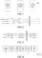
- FIG. 1 there is depicted a simplified functional block diagram of an imaging system 100 according to an embodiment of the present invention.
- This embodiment depicts two printers 102a and 102b associated and in communication with a single substrate unit 104.
- this is only for simplicity in creating and describing the drawings.
- the printers 102a, 102b can be thought of as expandable resources to the substrate unit 104, and either a greater number or a lesser number of printers 102a, 102b can be added to the imaging system 100 at different times and for different imaging jobs, as desired or available.
- the imaging system 100 receives image data, such as from a computer over a network interface. Depending upon the print job to be performed, either one, several, or all of the printers 102a, 102b will receive image data to be printed onto a common substrate.
- each of the printers 102a, 102b is informed by the substrate unit 104 when movement in the Y axis is completed, and the printers 102a, 102b can print some or all of their image data.
- a given printer 102a or 102b has completed its movement in the X axis, such as by actually printing a swath of image data, it then signals back to the substrate unit 104 that it has completed its motion.
- the printer 102a or 102b then waits until the substrate unit 104 completes the next movement of the substrate and sends a signal to the printer 102a or 102b of such, at which time the printer 102a or 102b prints a new portion of image data.
- This process repeats for all of the printers 102a, 102b, either synchronously or asynchronously, until the image has been rendered on the substrate by the imaging system 100.
- the print head 412 itself, X axis controller 402, and components 404 for motion of the print head 412 in the X axis are referred to as the printer 102a or 102b.
- the printer 102a or 102b also includes an image processor 406 that cuts the image data into bands or swaths that are printed in one or more pass across the substrate in the X axis while the substrate is held in the same position. In some embodiments that function is performed by the same controller 402 that controls X axis motion.
- Some embodiments also include a memory 408 to hold image data, such as until it is used to print onto the substrate.
- the memory 408 holds the entire image, even though the given printer 102a or 102b will only process and print a portion of the image.
- the given printer 102a or 102b only receives that portion of the image data that it will print onto the substrate.
- each of the printers 102a, 102b receives all of the image data that it will receive for a given job at the beginning of the print job.
- a printer 102a or 102b only receives that image data that it is to print in a given pass or iteration of the printer 102a or 102b.
- Some embodiments of the printer 102a or 102b include a communication module 410, such as for communicating with the substrate unit 104, as depicted in FIG. 1 , and receiving image data.
- the communication module 410 of a given printer 102a can communicate directly or indirectly with one or all of the other printers 102b.
- the architecture of the substrate unit 104 is as depicted in FIG. 5 , and is a separate and distinct piece of equipment from the printers 102a, 102b.
- the substrate unit 104 includes the Y axis controller 502, which is the only element of the system 100 that moves the substrate.
- the substrate unit 104 in some embodiments also includes components for the physical motion of the substrate in the Y axis, such as motors, belts, gears, bars, rails, tracks, platens, and other motion inducing elements.
- the substrate unit 104 includes an image processor 506.
- the substrate unit 104 functions as a master controller for the imaging system 100, by receiving the image data from the job source, as introduced above, storing it in a memory 508, dividing the job up amongst the printers 102a, 102b that have been attached to, associated with, and in communication with the substrate unit 104, and then sending that image data out to the printers 102a, 102b through the communication module 510.
- the substrate unit 104 can communicated the image data to the printers 102a, 102b in a variety of different ways. For example, in one embodiment all of the image data is sent to every one of the printers 102a, 102b, but then specific instructions as to what portion of the image data a given printer 102a or 102b is to print is sent to the given printer 102a or 102b, either at the start of the job or as the job progresses.
- printing the swaths under the control of the printers 102a, 102b is held until the substrate unit 104 has moved the substrate into the correct position.
- differing and multiple printers 102a, 102b can be paired with differing substrate units 104, and the resultant imaging systems 100 as described herein provide for proper communication between the one or more printer 102a, 102b and the substrate unit 104.
- the system 100 described herein allows for embodiments where multiple printers 102a, 102b operate independently of one another at the same time within a single integrated imaging system 100.
- each of these printers 102a, 102b coordinates separately with the substrate unit 104, which makes relative Y axis motion decisions in regard to the substrate based at least in part upon the input that it receives from all of the printers 102a, 102b incorporated into the overall imaging system 100.
- PRINT_WAIT 204 The substrate unit 104 sets this signal 204 high at events 206a, 206b, indicating that the printers 102a, 102b need to wait and not print. During the high state of signal 204, the substrate unit 104 can move the substrate without disrupting the operation of the printers 102a, 102b. Once this signal 204 is low, the printers 102a, 102b are free to print at least one swath before checking the state of signal 204 again.
- SCANNING 202 Once PRINT_WAIT 204 is set low, a printer 102a, 102b (either P1 or P2 as labeled in FIG. 2 ) sets this signal 202a or 202b high to indicate that it is printing a swath. The substrate unit 104 will not move the substrate until this signal 202a or 202b goes back to low under the control of the printer 102a or 102b that issues the signal 202a or 202b.
- the substrate unit 104 sets signal 204 high at events 206a, 206b indicating to the printers 102a, 102b that they should not print, because the substrate unit 104 is moving the substrate, or otherwise does not authorize a print procedure from one or more of the printers 102a, 102b.
- the substrate unit 104 sets the signal 204 to go low once again.
- the printers 102a, 102 b (P1 or P2 as indicated in FIG. 2 ) set their associated scan lines 202a, 202b high, such as at events 208a, 208b, which indicates to the substrate unit 104 that printing or some other operation is occurring and that the substrate should not be moved.
- the printers 102a, 102b have completed their print swath, for example, they set their respective scanning lines 202a, 202b low, such as at events 210a, 210a.
- the substrate unit 104 detects that the scan lines 202a, 202b are low, it understands that it can then initiate another movement of the substrate, and sets the print wait line 204 high, such as at event 206b, so that the printers 102a, 102b do not try to print while the substrate is being moved.
- This process of setting the signal lines 202a, 202b and 204 high and low to signal between the substrate unit 104 and the printers 102a, 102b continues until the print job is complete.
- USB universal serial bus
- the printer 102a or 102b accepts a command F1 or B1, respectively, from the substrate unit 104 that allows the given printer 102a or 102b to print one swath (for example), and after that swath is finished, the printer 102a or 102b returns a command Rx'd that indicates to the substrate unit 104 (1) that the printer 102a or 102b has completed the desired swath(s), and (2) the Y axis movement that the printer 102a or 102b desires the substrate unit 104 to perform.
- the substrate unit 104 then moves the substrate (or the entire printer 102a or 102b itself relative to the substrate) so as to be ready for the next swath.
- the communication between the printers 102a, 102b and the substrate unit 104 continues in this fashion (F2 B2, F3 B3, etc.) until the imaging job is complete.
- the synchronization between the printers 102a, 102b and the substrate unit 104 may include a pre-defined distance for the Y axis motion, or the distance of the Y axis motion may be communicated from the printers 102a, 102b to the substrate unit 104.
- a pre-defined distance a set of pre-defined modes can be provided, where different modes are associated with different pre-defined distances, and from which the desired mode is selected.
- each printer 102a or 102b can communicate to the substrate unit 104 the desired amount of Y axis motion.
- each printer 102a or 102b communicates a desired move distance to the substrate unit 104, and the Y axis controller 502 of the substrate unit 104 determines the actual Y axis move amount, which is then communicated back to the printers 102a, 102b, each of which, for example, adjusts its print swath width accordingly.
- the substrate is a piece of paper or other planar surface. In some embodiments the substrate is a three dimensionally-surfaced object. In some embodiments different printers 102a, 102b with different capabilities for printing on different substrate topologies and different substrate materials are used to print on different portions of a complex substrate, as needed. In some embodiments, movement of the substrate in the Y axis constitutes rotating the substrate, such as might be accomplished with a cylindrical substrate.
- one or more printers 102a, 102b print on one side of the substrate, while one or more printers 102a, 102b print on the other side of the substrate. In some embodiments different printers 102a, 102b print on different portions of the same side of the substrate.
- the printers 102a, 102b are associated with the substrate unit 104 by attaching a dedicated umbilical between each printer 102a or 102b and the substrate unit 104, where the umbilical provides all of the power and communication required by the printer 102a or 102b.
- the substrate is too large to move, and so the substrate unit 104 causes the entirety of a given printer 102a or 102b to move in the Y axis, and then the print head 412 of the printer 102a or 102b is moved in the X axis under the control of the X axis controller 402.
Landscapes
- Engineering & Computer Science (AREA)
- Theoretical Computer Science (AREA)
- Human Computer Interaction (AREA)
- Physics & Mathematics (AREA)
- General Engineering & Computer Science (AREA)
- General Physics & Mathematics (AREA)
- Ink Jet (AREA)
- Character Spaces And Line Spaces In Printers (AREA)
- Accessory Devices And Overall Control Thereof (AREA)
- Printers Characterized By Their Purpose (AREA)
Claims (8)
- Bildgebungssystem (100) zum Drucken eines Bildes auf ein Substrat, umfassend:eine Vielzahl an Druckern (102a, 102b), welche jeweils eine erste Steuereinheit (402) und eine Substrateinheit (104), welche eine zweite Steuereinheit (502) hat, aufweisen.wobei jeder Drucker umfasst:einen Druckkopf (412), der dazu konfiguriert ist, Bildinformationen auf einem Band entlang der ersten Richtung (X) zu drucken,eine erste Steuereinheit (402), die dazu konfiguriert ist, die Bewegung des Druckkopfs (412) in die erste Richtung zu kontrollieren, undein erstes Kommunikationsmodul (410), das dazu konfiguriert ist, Mitteilungen zu empfangen, um die erste Steuereinheit (402) zu informieren, dass das Drucken des Druckbands zulässig ist, und dazu konfiguriert ist, Mitteilungen zu senden, um die zweite Steuereinheit (502) zu informieren, dass das Drucken des Druckbands abgeschlossen ist, und;wobei die Substrateinheit (104) umfasst:die zweite Steuereinheit (502), die dazu konfiguriert ist, die Bewegung des Substrats in eine zweite Richtung des Substrats zu kontrollieren,ein zweites Kommunikationsmodul (510), das dazu konfiguriert ist, Mitteilungen zu senden, um jeden der Vielzahl an Druckern (102a, 102b) zu informieren, dass das Drucken des Druckbands zulässig ist, und um Mitteilungen von jedem der Vielzahl an Druckern (102a, 102b) zu empfangen, um anzuzeigen, dass das Drucken des Druckbands abgeschlossen ist,wobei das Bildgebungssystem (100) dadurch gekennzeichnet ist, dass die erste Steuereinheit (402) und die zweite Steuereinheit (502) einzeln und unabhängig sind,die Vielzahl an Druckern (102a, 102b), welche mit der Substrateinheit (104) kommunizieren und zum Drucken auf dem gleichen Substrat konfiguriert wurden.
- Bildgebungssystem (100) gemäß Anspruch 1, dadurch gekennzeichnet, dass jedes Auftreten von Bewegung in die zweite Richtung eine Bewegung mit vorbestimmter Entfernung ist.
- Bildgebungssystem (100) gemäß einem der Ansprüche 1 bis 2, dadurch gekennzeichnet, dass eine Bewegung in eine zweite Richtung, eine Bewegung mit einer wählbaren Entfernung, die zumindest teilweise auf einer Eingabe basiert, die von der Substrateinheit (104) vom Drucker (102a) empfangen wird, ist.
- Bildgebungssystem (100) gemäß einem der Ansprüche 1 bis 3, dadurch gekennzeichnet, dass das erste Kommunikationsmodul (410) dazu konfiguriert ist, um ein Signal an die Substrateinheit (104) auszugeben, um das Substrat anzuweisen, sich in die zweite Richtung zu bewegen, und
das zweite Kommunikationsmodul (510) dazu konfiguriert ist, ein Signal an den Drucker (102a) auszugeben, um den Druckkopf (412) anzuweisen, sich in die erste Richtung zu bewegen. - Bildgebungssystem (100) gemäß einem der Ansprüche 1 bis 4, dadurch gekennzeichnet, dass die Substrateinheit (104) eine Bewegung in die zweite Richtung durch das Bewegen des gesamten Druckers relativ zum Substrat, auslöst.
- Bildgebungssystem (100) gemäß einem der Ansprüche 1 bis 5, dadurch gekennzeichnet, dass die Kommunikation zwischen dem Drucker (102a) und der Substrateinheit (104) auf einem Universal Serial Bus Protokoll basiert.
- Bildgebungssystem (100) gemäß einem der Ansprüche 1 bis 6, dadurch gekennzeichnet, dass die Kommunikation zwischen Drucker (102a) und Substrateinheit (104) auf einem allgemeinen Eingabe-Ausgabe-Protokoll basiert.
- Bildgebungssystem (100) gemäß einem der Ansprüche 1 bis 7, dadurch gekennzeichnet, dass die erste Richtung perpendikulär zur zweiten Richtung ist.
Applications Claiming Priority (1)
| Application Number | Priority Date | Filing Date | Title |
|---|---|---|---|
| US15/132,387 US9830113B2 (en) | 2016-04-19 | 2016-04-19 | Imaging system controller coordination |
Publications (2)
| Publication Number | Publication Date |
|---|---|
| EP3235649A1 EP3235649A1 (de) | 2017-10-25 |
| EP3235649B1 true EP3235649B1 (de) | 2019-03-06 |
Family
ID=58549042
Family Applications (1)
| Application Number | Title | Priority Date | Filing Date |
|---|---|---|---|
| EP17166739.7A Active EP3235649B1 (de) | 2016-04-19 | 2017-04-18 | Bildgebungssystem |
Country Status (4)
| Country | Link |
|---|---|
| US (1) | US9830113B2 (de) |
| EP (1) | EP3235649B1 (de) |
| JP (1) | JP7039854B2 (de) |
| CN (1) | CN107443936B (de) |
Families Citing this family (1)
| Publication number | Priority date | Publication date | Assignee | Title |
|---|---|---|---|---|
| KR102749527B1 (ko) * | 2021-10-25 | 2025-01-02 | 김준기 | 안드로이드 어플리케이션에서 써멀 프린터를 구동하는 장치, 이의 제어방법 및 이를 기록한 기록매체 |
Family Cites Families (19)
| Publication number | Priority date | Publication date | Assignee | Title |
|---|---|---|---|---|
| US4196450A (en) * | 1977-01-18 | 1980-04-01 | Datacopy Corporation | Selective copying apparatus |
| US5140674A (en) * | 1988-09-23 | 1992-08-18 | Hewlett-Packard Company | Text and color printing system |
| JP2921035B2 (ja) * | 1989-10-12 | 1999-07-19 | ソニー株式会社 | サーマルプリンタの印画方法 |
| JP3155794B2 (ja) * | 1991-12-13 | 2001-04-16 | キヤノン株式会社 | インクジェット記録方法及びインクジェット記録装置 |
| US5351068A (en) | 1992-09-30 | 1994-09-27 | Hewlett-Packard Company | Ink-jet printer carriage and paper motion overlap method and apparatus |
| JP3166998B2 (ja) * | 1994-02-08 | 2001-05-14 | キヤノン株式会社 | 記録装置及び記録制御方法 |
| JP2001253579A (ja) * | 2000-03-10 | 2001-09-18 | Hitachi Koki Co Ltd | 印刷装置の搬送制御方法 |
| WO2004106068A1 (ja) * | 2003-06-02 | 2004-12-09 | Canon Finetech Inc. | 画像形成装置、該装置用のプリンタ複合システムおよび媒体搬送装置、前記画像形成装置に画像データを供給する情報処理装置、並びにこれらを具えた画像形成システムおよび画像形成方法 |
| TWI220886B (en) * | 2003-10-17 | 2004-09-11 | Benq Corp | Method and device for boosting printing speed of a printer |
| JP4412713B2 (ja) | 2004-01-29 | 2010-02-10 | キヤノン株式会社 | 記録装置、記録システム及び記録装置の制御方法 |
| US7463372B2 (en) | 2004-01-30 | 2008-12-09 | Canon Kabushiki Kaisha | Recording system and control method therefor |
| JP2007301881A (ja) | 2006-05-12 | 2007-11-22 | Kyocera Mita Corp | マルチポート印刷装置 |
| US20100177143A1 (en) * | 2007-06-15 | 2010-07-15 | Wp Digital Ag | Method for printing endless printing substrates digitally |
| JP5609392B2 (ja) * | 2010-07-30 | 2014-10-22 | セイコーエプソン株式会社 | 印刷制御装置、印刷装置及び印刷装置における印刷制御方法 |
| JP2012066576A (ja) * | 2010-08-25 | 2012-04-05 | Canon Inc | インクジェット記録装置及び記録方法 |
| JP2012232539A (ja) | 2011-05-09 | 2012-11-29 | Canon Inc | 印刷装置、データ処理装置、印刷装置の制御方法及びプログラム |
| US8511771B2 (en) * | 2011-06-14 | 2013-08-20 | Hewlett-Packard Development Company, L.P. | Printing system |
| JP2013166311A (ja) | 2012-02-15 | 2013-08-29 | Canon Inc | 画像処理装置、その制御方法、及びプログラム |
| JP6083176B2 (ja) * | 2012-09-27 | 2017-02-22 | ブラザー工業株式会社 | 印刷装置 |
-
2016
- 2016-04-19 US US15/132,387 patent/US9830113B2/en not_active Expired - Fee Related
-
2017
- 2017-04-17 JP JP2017081450A patent/JP7039854B2/ja active Active
- 2017-04-17 CN CN201710251022.9A patent/CN107443936B/zh not_active Expired - Fee Related
- 2017-04-18 EP EP17166739.7A patent/EP3235649B1/de active Active
Non-Patent Citations (1)
| Title |
|---|
| None * |
Also Published As
| Publication number | Publication date |
|---|---|
| US9830113B2 (en) | 2017-11-28 |
| JP2017193174A (ja) | 2017-10-26 |
| CN107443936B (zh) | 2019-11-05 |
| US20170300273A1 (en) | 2017-10-19 |
| EP3235649A1 (de) | 2017-10-25 |
| JP7039854B2 (ja) | 2022-03-23 |
| CN107443936A (zh) | 2017-12-08 |
Similar Documents
| Publication | Publication Date | Title |
|---|---|---|
| JP5849395B2 (ja) | 記録方法及び記録装置 | |
| US8570575B2 (en) | Image forming apparatus, method of controlling the same, and image processing apparatus performing image formation on the basis of a plurality of pieces of image data for different colors | |
| EP0867002A1 (de) | Intelligenter druckkopfschlitten, der einen schaltkreis zur datenverarbeitung enthält | |
| US20110157648A1 (en) | Data Pump For Printing | |
| US20090195570A1 (en) | Recording system, recording apparatus and recording method of recording apparatus | |
| US20060082814A1 (en) | Printing system architecture | |
| JP6708478B2 (ja) | 画像形成装置、画像形成方法およびプログラム | |
| EP3235649B1 (de) | Bildgebungssystem | |
| JP2012152956A (ja) | 記録方法及び記録装置 | |
| CN101109949B (zh) | 用于在机械加工设备和传递装置之间交换信息的系统 | |
| JP5504920B2 (ja) | 流体噴射制御装置、流体噴射装置及び流体噴射制御方法 | |
| EP1690629B1 (de) | Laserbearbeitungssystem | |
| US8917421B2 (en) | Printing apparatus and method of controlling printing apparatus | |
| JP2005119122A (ja) | 印刷装置、印刷処理方法およびそのプログラム | |
| US20070109588A1 (en) | Image forming system, printing apparatus fot the system, and image forming method | |
| US7481516B2 (en) | Inkjet recording apparatus and inkjet recording method | |
| JP5135407B2 (ja) | インクジェット印刷機のプリントヘッド制御装置 | |
| JP2012192600A (ja) | 記録装置、記録システム、記録装置の制御方法、及び、プログラム | |
| EP1065066B1 (de) | Verminderung von Schrittfehlern durch abwechselnde Druckkopfausstossmodi | |
| JP2019177546A (ja) | 記録装置、記録装置の制御方法、及びプログラム | |
| JPS60145867A (ja) | 印字ヘツド制御方式 | |
| JP2017149117A (ja) | 記録装置、記録方法およびプログラム | |
| FI74174B (fi) | Telexapparat. | |
| JP2003167710A (ja) | 記録装置および記録システム | |
| EP1479522A1 (de) | Verfahren und Vorrichtung zum Drucken mit einem konstanten Druckmedientransportabstand |
Legal Events
| Date | Code | Title | Description |
|---|---|---|---|
| PUAI | Public reference made under article 153(3) epc to a published international application that has entered the european phase |
Free format text: ORIGINAL CODE: 0009012 |
|
| STAA | Information on the status of an ep patent application or granted ep patent |
Free format text: STATUS: THE APPLICATION HAS BEEN PUBLISHED |
|
| AK | Designated contracting states |
Kind code of ref document: A1 Designated state(s): AL AT BE BG CH CY CZ DE DK EE ES FI FR GB GR HR HU IE IS IT LI LT LU LV MC MK MT NL NO PL PT RO RS SE SI SK SM TR |
|
| AX | Request for extension of the european patent |
Extension state: BA ME |
|
| STAA | Information on the status of an ep patent application or granted ep patent |
Free format text: STATUS: REQUEST FOR EXAMINATION WAS MADE |
|
| 17P | Request for examination filed |
Effective date: 20180405 |
|
| RBV | Designated contracting states (corrected) |
Designated state(s): AL AT BE BG CH CY CZ DE DK EE ES FI FR GB GR HR HU IE IS IT LI LT LU LV MC MK MT NL NO PL PT RO RS SE SI SK SM TR |
|
| GRAP | Despatch of communication of intention to grant a patent |
Free format text: ORIGINAL CODE: EPIDOSNIGR1 |
|
| STAA | Information on the status of an ep patent application or granted ep patent |
Free format text: STATUS: GRANT OF PATENT IS INTENDED |
|
| INTG | Intention to grant announced |
Effective date: 20181010 |
|
| GRAS | Grant fee paid |
Free format text: ORIGINAL CODE: EPIDOSNIGR3 |
|
| GRAA | (expected) grant |
Free format text: ORIGINAL CODE: 0009210 |
|
| STAA | Information on the status of an ep patent application or granted ep patent |
Free format text: STATUS: THE PATENT HAS BEEN GRANTED |
|
| AK | Designated contracting states |
Kind code of ref document: B1 Designated state(s): AL AT BE BG CH CY CZ DE DK EE ES FI FR GB GR HR HU IE IS IT LI LT LU LV MC MK MT NL NO PL PT RO RS SE SI SK SM TR |
|
| REG | Reference to a national code |
Ref country code: GB Ref legal event code: FG4D |
|
| REG | Reference to a national code |
Ref country code: CH Ref legal event code: EP Ref country code: AT Ref legal event code: REF Ref document number: 1104013 Country of ref document: AT Kind code of ref document: T Effective date: 20190315 |
|
| REG | Reference to a national code |
Ref country code: DE Ref legal event code: R096 Ref document number: 602017002441 Country of ref document: DE |
|
| REG | Reference to a national code |
Ref country code: IE Ref legal event code: FG4D |
|
| REG | Reference to a national code |
Ref country code: NL Ref legal event code: MP Effective date: 20190306 |
|
| REG | Reference to a national code |
Ref country code: LT Ref legal event code: MG4D |
|
| PG25 | Lapsed in a contracting state [announced via postgrant information from national office to epo] |
Ref country code: FI Free format text: LAPSE BECAUSE OF FAILURE TO SUBMIT A TRANSLATION OF THE DESCRIPTION OR TO PAY THE FEE WITHIN THE PRESCRIBED TIME-LIMIT Effective date: 20190306 Ref country code: LT Free format text: LAPSE BECAUSE OF FAILURE TO SUBMIT A TRANSLATION OF THE DESCRIPTION OR TO PAY THE FEE WITHIN THE PRESCRIBED TIME-LIMIT Effective date: 20190306 Ref country code: NO Free format text: LAPSE BECAUSE OF FAILURE TO SUBMIT A TRANSLATION OF THE DESCRIPTION OR TO PAY THE FEE WITHIN THE PRESCRIBED TIME-LIMIT Effective date: 20190606 Ref country code: SE Free format text: LAPSE BECAUSE OF FAILURE TO SUBMIT A TRANSLATION OF THE DESCRIPTION OR TO PAY THE FEE WITHIN THE PRESCRIBED TIME-LIMIT Effective date: 20190306 |
|
| PG25 | Lapsed in a contracting state [announced via postgrant information from national office to epo] |
Ref country code: RS Free format text: LAPSE BECAUSE OF FAILURE TO SUBMIT A TRANSLATION OF THE DESCRIPTION OR TO PAY THE FEE WITHIN THE PRESCRIBED TIME-LIMIT Effective date: 20190306 Ref country code: NL Free format text: LAPSE BECAUSE OF FAILURE TO SUBMIT A TRANSLATION OF THE DESCRIPTION OR TO PAY THE FEE WITHIN THE PRESCRIBED TIME-LIMIT Effective date: 20190306 Ref country code: LV Free format text: LAPSE BECAUSE OF FAILURE TO SUBMIT A TRANSLATION OF THE DESCRIPTION OR TO PAY THE FEE WITHIN THE PRESCRIBED TIME-LIMIT Effective date: 20190306 Ref country code: GR Free format text: LAPSE BECAUSE OF FAILURE TO SUBMIT A TRANSLATION OF THE DESCRIPTION OR TO PAY THE FEE WITHIN THE PRESCRIBED TIME-LIMIT Effective date: 20190607 Ref country code: HR Free format text: LAPSE BECAUSE OF FAILURE TO SUBMIT A TRANSLATION OF THE DESCRIPTION OR TO PAY THE FEE WITHIN THE PRESCRIBED TIME-LIMIT Effective date: 20190306 Ref country code: BG Free format text: LAPSE BECAUSE OF FAILURE TO SUBMIT A TRANSLATION OF THE DESCRIPTION OR TO PAY THE FEE WITHIN THE PRESCRIBED TIME-LIMIT Effective date: 20190606 |
|
| REG | Reference to a national code |
Ref country code: AT Ref legal event code: MK05 Ref document number: 1104013 Country of ref document: AT Kind code of ref document: T Effective date: 20190306 |
|
| PG25 | Lapsed in a contracting state [announced via postgrant information from national office to epo] |
Ref country code: EE Free format text: LAPSE BECAUSE OF FAILURE TO SUBMIT A TRANSLATION OF THE DESCRIPTION OR TO PAY THE FEE WITHIN THE PRESCRIBED TIME-LIMIT Effective date: 20190306 Ref country code: IT Free format text: LAPSE BECAUSE OF FAILURE TO SUBMIT A TRANSLATION OF THE DESCRIPTION OR TO PAY THE FEE WITHIN THE PRESCRIBED TIME-LIMIT Effective date: 20190306 Ref country code: CZ Free format text: LAPSE BECAUSE OF FAILURE TO SUBMIT A TRANSLATION OF THE DESCRIPTION OR TO PAY THE FEE WITHIN THE PRESCRIBED TIME-LIMIT Effective date: 20190306 Ref country code: RO Free format text: LAPSE BECAUSE OF FAILURE TO SUBMIT A TRANSLATION OF THE DESCRIPTION OR TO PAY THE FEE WITHIN THE PRESCRIBED TIME-LIMIT Effective date: 20190306 Ref country code: PT Free format text: LAPSE BECAUSE OF FAILURE TO SUBMIT A TRANSLATION OF THE DESCRIPTION OR TO PAY THE FEE WITHIN THE PRESCRIBED TIME-LIMIT Effective date: 20190706 Ref country code: ES Free format text: LAPSE BECAUSE OF FAILURE TO SUBMIT A TRANSLATION OF THE DESCRIPTION OR TO PAY THE FEE WITHIN THE PRESCRIBED TIME-LIMIT Effective date: 20190306 Ref country code: SK Free format text: LAPSE BECAUSE OF FAILURE TO SUBMIT A TRANSLATION OF THE DESCRIPTION OR TO PAY THE FEE WITHIN THE PRESCRIBED TIME-LIMIT Effective date: 20190306 Ref country code: AL Free format text: LAPSE BECAUSE OF FAILURE TO SUBMIT A TRANSLATION OF THE DESCRIPTION OR TO PAY THE FEE WITHIN THE PRESCRIBED TIME-LIMIT Effective date: 20190306 |
|
| PG25 | Lapsed in a contracting state [announced via postgrant information from national office to epo] |
Ref country code: PL Free format text: LAPSE BECAUSE OF FAILURE TO SUBMIT A TRANSLATION OF THE DESCRIPTION OR TO PAY THE FEE WITHIN THE PRESCRIBED TIME-LIMIT Effective date: 20190306 Ref country code: SM Free format text: LAPSE BECAUSE OF FAILURE TO SUBMIT A TRANSLATION OF THE DESCRIPTION OR TO PAY THE FEE WITHIN THE PRESCRIBED TIME-LIMIT Effective date: 20190306 |
|
| REG | Reference to a national code |
Ref country code: DE Ref legal event code: R097 Ref document number: 602017002441 Country of ref document: DE |
|
| REG | Reference to a national code |
Ref country code: BE Ref legal event code: MM Effective date: 20190430 |
|
| PG25 | Lapsed in a contracting state [announced via postgrant information from national office to epo] |
Ref country code: AT Free format text: LAPSE BECAUSE OF FAILURE TO SUBMIT A TRANSLATION OF THE DESCRIPTION OR TO PAY THE FEE WITHIN THE PRESCRIBED TIME-LIMIT Effective date: 20190306 Ref country code: LU Free format text: LAPSE BECAUSE OF NON-PAYMENT OF DUE FEES Effective date: 20190418 Ref country code: IS Free format text: LAPSE BECAUSE OF FAILURE TO SUBMIT A TRANSLATION OF THE DESCRIPTION OR TO PAY THE FEE WITHIN THE PRESCRIBED TIME-LIMIT Effective date: 20190706 |
|
| PLBE | No opposition filed within time limit |
Free format text: ORIGINAL CODE: 0009261 |
|
| STAA | Information on the status of an ep patent application or granted ep patent |
Free format text: STATUS: NO OPPOSITION FILED WITHIN TIME LIMIT |
|
| PG25 | Lapsed in a contracting state [announced via postgrant information from national office to epo] |
Ref country code: MC Free format text: LAPSE BECAUSE OF FAILURE TO SUBMIT A TRANSLATION OF THE DESCRIPTION OR TO PAY THE FEE WITHIN THE PRESCRIBED TIME-LIMIT Effective date: 20190306 Ref country code: DK Free format text: LAPSE BECAUSE OF FAILURE TO SUBMIT A TRANSLATION OF THE DESCRIPTION OR TO PAY THE FEE WITHIN THE PRESCRIBED TIME-LIMIT Effective date: 20190306 |
|
| 26N | No opposition filed |
Effective date: 20191209 |
|
| PG25 | Lapsed in a contracting state [announced via postgrant information from national office to epo] |
Ref country code: SI Free format text: LAPSE BECAUSE OF FAILURE TO SUBMIT A TRANSLATION OF THE DESCRIPTION OR TO PAY THE FEE WITHIN THE PRESCRIBED TIME-LIMIT Effective date: 20190306 Ref country code: BE Free format text: LAPSE BECAUSE OF NON-PAYMENT OF DUE FEES Effective date: 20190430 |
|
| PG25 | Lapsed in a contracting state [announced via postgrant information from national office to epo] |
Ref country code: TR Free format text: LAPSE BECAUSE OF FAILURE TO SUBMIT A TRANSLATION OF THE DESCRIPTION OR TO PAY THE FEE WITHIN THE PRESCRIBED TIME-LIMIT Effective date: 20190306 |
|
| PG25 | Lapsed in a contracting state [announced via postgrant information from national office to epo] |
Ref country code: IE Free format text: LAPSE BECAUSE OF NON-PAYMENT OF DUE FEES Effective date: 20190418 |
|
| PG25 | Lapsed in a contracting state [announced via postgrant information from national office to epo] |
Ref country code: FR Free format text: LAPSE BECAUSE OF NON-PAYMENT OF DUE FEES Effective date: 20190506 |
|
| REG | Reference to a national code |
Ref country code: CH Ref legal event code: PL |
|
| PG25 | Lapsed in a contracting state [announced via postgrant information from national office to epo] |
Ref country code: CH Free format text: LAPSE BECAUSE OF NON-PAYMENT OF DUE FEES Effective date: 20200430 Ref country code: LI Free format text: LAPSE BECAUSE OF NON-PAYMENT OF DUE FEES Effective date: 20200430 |
|
| PG25 | Lapsed in a contracting state [announced via postgrant information from national office to epo] |
Ref country code: CY Free format text: LAPSE BECAUSE OF FAILURE TO SUBMIT A TRANSLATION OF THE DESCRIPTION OR TO PAY THE FEE WITHIN THE PRESCRIBED TIME-LIMIT Effective date: 20190306 |
|
| PG25 | Lapsed in a contracting state [announced via postgrant information from national office to epo] |
Ref country code: MT Free format text: LAPSE BECAUSE OF FAILURE TO SUBMIT A TRANSLATION OF THE DESCRIPTION OR TO PAY THE FEE WITHIN THE PRESCRIBED TIME-LIMIT Effective date: 20190306 Ref country code: HU Free format text: LAPSE BECAUSE OF FAILURE TO SUBMIT A TRANSLATION OF THE DESCRIPTION OR TO PAY THE FEE WITHIN THE PRESCRIBED TIME-LIMIT; INVALID AB INITIO Effective date: 20170418 |
|
| GBPC | Gb: european patent ceased through non-payment of renewal fee |
Effective date: 20210418 |
|
| PG25 | Lapsed in a contracting state [announced via postgrant information from national office to epo] |
Ref country code: GB Free format text: LAPSE BECAUSE OF NON-PAYMENT OF DUE FEES Effective date: 20210418 |
|
| PG25 | Lapsed in a contracting state [announced via postgrant information from national office to epo] |
Ref country code: MK Free format text: LAPSE BECAUSE OF FAILURE TO SUBMIT A TRANSLATION OF THE DESCRIPTION OR TO PAY THE FEE WITHIN THE PRESCRIBED TIME-LIMIT Effective date: 20190306 |
|
| PGFP | Annual fee paid to national office [announced via postgrant information from national office to epo] |
Ref country code: DE Payment date: 20250528 Year of fee payment: 9 |
|
| REG | Reference to a national code |
Ref country code: DE Ref legal event code: R081 Ref document number: 602017002441 Country of ref document: DE Owner name: BRADY WORLDWIDE, INC., MILWAUKEE, US Free format text: FORMER OWNER: FUNAI ELECTRIC CO., LTD., DAITO, OSAKA, JP Ref country code: DE Ref legal event code: R082 Ref document number: 602017002441 Country of ref document: DE Representative=s name: BOULT WADE TENNANT LLP, DE |