EP3234682B1 - Deployment mechanism for optical measurement system - Google Patents
Deployment mechanism for optical measurement system Download PDFInfo
- Publication number
- EP3234682B1 EP3234682B1 EP15870616.8A EP15870616A EP3234682B1 EP 3234682 B1 EP3234682 B1 EP 3234682B1 EP 15870616 A EP15870616 A EP 15870616A EP 3234682 B1 EP3234682 B1 EP 3234682B1
- Authority
- EP
- European Patent Office
- Prior art keywords
- optical
- measurement system
- axis
- sensor assembly
- along
- Prior art date
- Legal status (The legal status is an assumption and is not a legal conclusion. Google has not performed a legal analysis and makes no representation as to the accuracy of the status listed.)
- Active
Links
- 238000005259 measurement Methods 0.000 title claims description 91
- 230000003287 optical effect Effects 0.000 title claims description 86
- 230000007246 mechanism Effects 0.000 title claims description 26
- 238000005286 illumination Methods 0.000 description 4
- 239000000523 sample Substances 0.000 description 4
- 230000013011 mating Effects 0.000 description 3
- 230000000295 complement effect Effects 0.000 description 2
- 230000008878 coupling Effects 0.000 description 2
- 238000010168 coupling process Methods 0.000 description 2
- 238000005859 coupling reaction Methods 0.000 description 2
- 238000007689 inspection Methods 0.000 description 2
- 230000004913 activation Effects 0.000 description 1
- 230000008859 change Effects 0.000 description 1
- 239000000835 fiber Substances 0.000 description 1
- 238000003384 imaging method Methods 0.000 description 1
- 238000004519 manufacturing process Methods 0.000 description 1
- 238000000034 method Methods 0.000 description 1
- 238000012986 modification Methods 0.000 description 1
- 230000004048 modification Effects 0.000 description 1
- 238000012806 monitoring device Methods 0.000 description 1
- 238000012634 optical imaging Methods 0.000 description 1
Images


Classifications
-
- G—PHYSICS
- G01—MEASURING; TESTING
- G01B—MEASURING LENGTH, THICKNESS OR SIMILAR LINEAR DIMENSIONS; MEASURING ANGLES; MEASURING AREAS; MEASURING IRREGULARITIES OF SURFACES OR CONTOURS
- G01B11/00—Measuring arrangements characterised by the use of optical techniques
- G01B11/02—Measuring arrangements characterised by the use of optical techniques for measuring length, width or thickness
- G01B11/022—Measuring arrangements characterised by the use of optical techniques for measuring length, width or thickness by means of tv-camera scanning
-
- G—PHYSICS
- G01—MEASURING; TESTING
- G01B—MEASURING LENGTH, THICKNESS OR SIMILAR LINEAR DIMENSIONS; MEASURING ANGLES; MEASURING AREAS; MEASURING IRREGULARITIES OF SURFACES OR CONTOURS
- G01B11/00—Measuring arrangements characterised by the use of optical techniques
- G01B11/002—Measuring arrangements characterised by the use of optical techniques for measuring two or more coordinates
- G01B11/005—Measuring arrangements characterised by the use of optical techniques for measuring two or more coordinates coordinate measuring machines
-
- G—PHYSICS
- G01—MEASURING; TESTING
- G01B—MEASURING LENGTH, THICKNESS OR SIMILAR LINEAR DIMENSIONS; MEASURING ANGLES; MEASURING AREAS; MEASURING IRREGULARITIES OF SURFACES OR CONTOURS
- G01B21/00—Measuring arrangements or details thereof, where the measuring technique is not covered by the other groups of this subclass, unspecified or not relevant
- G01B21/02—Measuring arrangements or details thereof, where the measuring technique is not covered by the other groups of this subclass, unspecified or not relevant for measuring length, width, or thickness
- G01B21/04—Measuring arrangements or details thereof, where the measuring technique is not covered by the other groups of this subclass, unspecified or not relevant for measuring length, width, or thickness by measuring coordinates of points
- G01B21/047—Accessories, e.g. for positioning, for tool-setting, for measuring probes
-
- G—PHYSICS
- G01—MEASURING; TESTING
- G01B—MEASURING LENGTH, THICKNESS OR SIMILAR LINEAR DIMENSIONS; MEASURING ANGLES; MEASURING AREAS; MEASURING IRREGULARITIES OF SURFACES OR CONTOURS
- G01B5/00—Measuring arrangements characterised by the use of mechanical techniques
- G01B5/004—Measuring arrangements characterised by the use of mechanical techniques for measuring coordinates of points
- G01B5/008—Measuring arrangements characterised by the use of mechanical techniques for measuring coordinates of points using coordinate measuring machines
- G01B5/012—Contact-making feeler heads therefor
-
- G—PHYSICS
- G02—OPTICS
- G02B—OPTICAL ELEMENTS, SYSTEMS OR APPARATUS
- G02B21/00—Microscopes
- G02B21/24—Base structure
- G02B21/26—Stages; Adjusting means therefor
-
- G—PHYSICS
- G02—OPTICS
- G02B—OPTICAL ELEMENTS, SYSTEMS OR APPARATUS
- G02B21/00—Microscopes
- G02B21/06—Means for illuminating specimens
- G02B21/08—Condensers
- G02B21/082—Condensers for incident illumination only
- G02B21/084—Condensers for incident illumination only having annular illumination around the objective
Definitions
- This invention relates to an optical measurement system for optically inspecting an object.
- Metrological machines are often employed for optical inspection of a manufactured object and for obtaining precise dimensional measurements of the manufactured object to ensure the object conforms to specifications.
- Such machines typically include a support or stage on which the object rests during inspection, and an optical sensor, such as a video camera, for recording and/or displaying images of the object.
- an optical sensor such as a video camera
- the video camera and the stage are movable with respect to one another so that different views of the object can be obtained at desired, precise locations.
- Such systems are often programmable, so that the same sequence of multiple images may be obtained for a number of similar manufactured objects.
- the secondary measurement aid can inhibit movement between the primary optical sensor and the object to be measured, thus potentially compromising the ability to obtain measurements of the object at all desired locations.
- the secondary measurement aid could be removed, such removal can be time-consuming, thus compromising cycle time for obtaining all desired measurements when removal of the secondary measurement aid was otherwise not necessary.
- US 5 615 489 A discloses a portal type coordinate measuring apparatus, wherein a video camera and a touch probe are suspended from a portal for movement relative to a stationary stage.
- the pivot axis of the probe is lower than a lens of the camera.
- US 2002/0191280 A1 discloses a microscope for operation.
- a positioning unit for positioning an optical unit and a corresponding monitoring device are disclosed in US 2013/0003170 A1 .
- This invention provides an optical measurement system according to claim 1. It comprises: an optical sensor assembly including an objective lens with an optical axis and a lens housing; a stage for placement of an object to be measured located beneath the optical sensor assembly, the stage and the optical sensor assembly being movable with respect to one another; and a deployment mechanism pivotally connected relative to the optical sensor assembly that moves a secondary measurement aid between a deployed position and a retracted position.
- the deployment mechanism includes an attachment mount, wherein at least two different types of secondary measurement aids may be interchangeably attached thereto.
- no measurement aids inhibit movement of the optical sensor assembly with respect to an object to be measured on the stage.
- the secondary measurement aid when in the deployed position, the secondary measurement aid is aligned along the optical axis, and when in the retracted position, the secondary measurement aid is no lower than a lowest portion of the lens housing.
- the stage and the optical sensor assembly are movable with respect to one another along each of the x, y and z axes, and when the deployment mechanism is in the deployed position, the secondary measurement aid is aligned along the optical axis, and when in the retracted position, the secondary measurement aid does not inhibit movement of the optical sensor assembly with respect to an object to be measured along each of the x, y, z axes.
- a pivot axis of the secondary measurement aid is generally horizontal and no lower than the objective lens. It may be above the objective lens.
- the secondary measurement aid is a touch sensor, and when in the deployed position, the touch sensor is aligned along the optical axis, and when in the retracted position, the touch sensor is no lower than a lowest portion of the lens housing.
- the touch sensor may include a stylus. When in the retracted position, the longitudinal axis of the touch sensor may be generally horizontal.
- the secondary measurement aid is provided on a rotary table.
- the axis of rotation of the rotary table may be aligned along the optical axis of the objective lens.
- the optical sensor assembly includes a camera, such as a video camera, or a scanning sensor.
- the stage is movable along the x and y axes
- the optical sensor assembly may be movable along the z axis.
- the secondary measurement aid comprises a mirror.
- the mirror When the mirror is in the deployed position, the mirror may be adjustably tiltable.
- a touch sensor and a mirror are interchangeably attachable to an attachment mount of the deployment mechanism.
- the deployment mechanism includes a pivot arm comprising a pivot connection at one end and an attachment mount for the secondary measurement aid at an opposite end.
- the pivot arm may be movable between the deployed position and the retracted position by an actuator, such as an air cylinder.
- the secondary measurement aid comprises a laser or a secondary lens for changing magnification or focal depth of the objective lens.
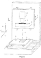
- FIGs. 1 to 7 illustrate an optical measurement system 1 that incorporates various embodiments of this invention.
- system 1 includes an optical sensor assembly that includes an optical sensor 2 and an objective lens 3 having optical axis 4.
- the optical sensor assembly may further include other conventional components, such as lights 9 for illuminating the object 5 to be measured when the object 5 is placed on stage 6 located beneath optical sensor assembly.
- the optical sensor assembly includes a video camera 2 as the optical sensor.
- stage 6 and the optical sensor assembly are movable with respect to one another.
- stage 6 is moveable along the x and y axes
- optical sensor assembly is movable along the z axes which is normal to the y axis, but other configurations are possible.
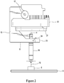
- FIGs. 2 to 7 illustrate a deployment mechanism according to embodiments of this invention in more detail.
- Deployment mechanism 10 is pivotally connected relative to the optical sensor.
- deployment mechanism 10 includes a pivot arm 11, connected at pivotal connection 12.
- a secondary measurement aid is attached to the deployment mechanism 10 at an opposite end.
- the secondary measurement aid includes touch sensor 14 comprising stylus 15.
- touch sensors are available under the tradename RenishawTM (Renishaw Inc., Hoffman Estates, Illinois, USA).
- Touch sensors include touch scanning sensors that contact the surface of an object along a preselected path, and touch trigger sensors that contact the surface of the object at multiple points.
- touch sensors may be used to measure features or contours of surfaces that are not easily accessible by the optical sensor, such as internal bores or threaded portions.
- FIG. 2 illustrates the secondary measurement aid in a deployed position.
- the longitudinal axis of touch sensor 14 is aligned with the optical axis 4 of the objective lens 3.
- the objective lens 3 and a light ring 9 are encased in lens housing 20.
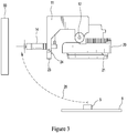
- FIG. 3 illustrates the secondary measurement aid in a retracted position, as the secondary measurement aid and pivot arm 11 have traveled along path 25.
- the secondary measurement aid in this case touch sensor 14, does not inhibit movement of the optical sensor assembly with respect to object 5 to be the measured in any of the x, y or z axes.
- optical sensor 2 and stage 6 can be moved fully in all directions with respect to one another, and viewing or optical imaging of the object 5 is not restricted.
- No measurement aids inhibit movement of the optical sensor assembly with respect to the object 5 to be measured on stage 6 or interfere with the field of view of the optical sensor.
- touch sensor 14 secondary measurement aid is no lower than the lowest portion 21 of the lens housing 20. Touch sensor 14 thus accesses the same measurement volume as optical sensor 2. Also, pivot axis 12 is generally horizontal and is located above the objective lens.
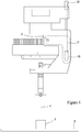
- an actuator 30 is provided to move the pivot arm 11 between the retracted and deployed positions.
- FIG. 4 illustrates an actuator arm 31 connected to an air cylinder 32, but other actuators may be employed, such as a ball screw, motorized rotary screw or linear motor.
- an end-of-travel, hard stop may be provided for accurate return to the deployed position. If desired, this hard stop may be cushioned, for example, by a gas spring cushion, to prevent undue wear on parts. Additionally, it is desired to prevent axial motion of pivot arm at pivot axis 12.
- radial angular contact bearings may be employed on at least one side of pivot axis 12 to prevent axial motion.
- a radial angular contact bearing may be provided on one side of pivot axis 12, and a standard radial bearing on the other side for additional support. Accordingly, all degrees of freedom of movement of pivot arm 11 are removed except along path 25; and the end-of-travel stop at the deployed position assures accuracy of the pivot arm reaching this deployed position while removing this final degree of freedom of movement of the pivot arm.
- a kinematic coupling between the pivot arm and the housing may be employed to assure the deployment mechanism 10 is returned accurately to the deployed position and to provide an end-of-travel stop.
- the pivot arm still travels along path 25 between the retracted position and the deployed position, but the pivot arm may be permitted to travel axially along the pivot axis.
- the pivot arm includes a physical mating feature that mates with a complementary physical mating feature on the apparatus housing. Once in the deployed position along path 25, the pivot arm is moved axially so that the complementary mating features interlock, thus providing the kinematic coupling that prevents movement of the pivot arm in all directions.
- secondary measurement aids besides a touch sensor may be employed, such as a scanning sensor, a laser sensor, or a secondary lens for changing magnification or focal depth of the objective lens.
- the secondary measurement aid may be permanently attached to deployment mechanism 10, but according to various embodiments, different types of secondary measurement aids may be interchangeably attached to an attachment mount 23 at the end of pivot arm 11.
- FIG. 5 illustrates an embodiment where touch sensor 14 has been replaced with mirror assembly 35.
- Mirror assembly 35 may be adjustably tiltable with respect to the optical sensor axis when in the deployed position.
- FIG. 6 illustrates an embodiment where the deployment mechanism includes a rotary table 40, which may be permanently or removably attached to attachment mount 23.
- a secondary measurement aid 41 is mounted to rotary table 40.
- the axis of rotation of rotary table 40 may be coincident with optical axis 4.
- the secondary measurement aid 41 may be a laser probe, with its sensing axis generally parallel to the stage, so that the laser probe may be pointed at different angles by rotating table 40.
- the secondary measurement aid 41 may be a small camera with a short focal distance, with its axis essentially parallel to the stage, so that this camera may be rotated by the rotary table 40.
- the sides of an object 5 may be sensed with the secondary measurement aid 41 while the optical sensor 2 primarily senses the object top.
- secondary measurement aid 41 may be an illumination source, such as a series of LEDs, a fiber bundle or a slit illuminator. Accordingly, the rotary table 40 may be rotated to change the orientation of illumination from this illumination source directed on object 5. For example, by rotating table 40 when in the deployed position, the orientation of light from the illumination source can be varied so that light strikes object 5 at different, desired angles of incidence in azimuth.
- Rotary table 40 may have an aperture of appropriate size that is concentric with its rotational axis to allow imaging with the optical sensor 2 through the aperture.
- secondary measurement aid 41 may be a mirror assembly, similar to the mirror assembly 35 of FIG. 5 , but attached to the rotary table 40.
- Rotary table 40 may have an aperture to allow the optical sensor 2 to view images from the mirror assembly on rotary table 40.
- the mirror assembly on rotary table 40 may rotate 360 degrees so that all sides of object 5 are viewable. Additionally, internal walls of object 5 may be viewed by optical sensor 2 when the mirror is able to fit inside an internal cavity of the object.
- the various secondary measurement aids may be attached to an attachment mount 23 located at the end of pivot arm 11.
- the attachment mount may be integrally formed with the pivot arm, or, as in the illustrated embodiment, attachment mount 23 may be a separate part located at the end of pivot arm 11.
- attachment mount includes removable fasteners 24, such as screws, so that an operator may interchange secondary measurement aids.
- a quick-connect attachment may be employed instead.
- a dockable device 50 including conventional pick- and-place elements, may be employed to interchange secondary measurement aids.
- Such dockable devices find use in changing of tools for various applications, such as in CNC machine centers, for example.
- the first object 5 to be measured is placed on stage 6.
- Touch sensor 14 is moved from the retracted position to the deployed position via activation of actuator 30.
- the stage 6 and optical sensor 2 are moved with respect to one another to take a desired first set of measurements with touch sensor 14.
- the touch sensor 14 is moved to the retracted position, and optical sensor and object 5 are repositioned to take a second set of measurements employing optical sensor 2 that do not require deployment of the touch sensor. It will be appreciated that since the touch sensor has been moved to the retracted position by the deployment mechanism of this invention, movement of the optical sensor assembly with respect to the object being measured is not inhibited, thereby permitting optical measurements that otherwise may not have been possible, or that would have at least required reorientation of the object on the stage.
- a different secondary measurement aid may be interchanged with the touch sensor, either manually or automatically via an automated dockable device, and then the pivot arm is again moved to the deployed position.
- a new set of optical measurements may be taken, employing the mirror to obtain optical measurements at angles offset from optical axis 4. Then, the mirror may be moved to the retracted position.
- a second object may be placed on the stage, and the sequence repeated.
- many optical metrology systems are programmable, so that the system takes the same sets of measurements, and positions each of the measurement aids in desired positions, with minimal operator intervention.
Landscapes
- Physics & Mathematics (AREA)
- General Physics & Mathematics (AREA)
- Chemical & Material Sciences (AREA)
- Analytical Chemistry (AREA)
- Optics & Photonics (AREA)
- Length Measuring Devices By Optical Means (AREA)
- Length Measuring Devices With Unspecified Measuring Means (AREA)
- Microscoopes, Condenser (AREA)
Applications Claiming Priority (2)
| Application Number | Priority Date | Filing Date | Title |
|---|---|---|---|
| US201462094688P | 2014-12-19 | 2014-12-19 | |
| PCT/US2015/062126 WO2016099815A1 (en) | 2014-12-19 | 2015-11-23 | Deployment mechanism for optical measurement system |
Publications (3)
| Publication Number | Publication Date |
|---|---|
| EP3234682A1 EP3234682A1 (en) | 2017-10-25 |
| EP3234682A4 EP3234682A4 (en) | 2018-07-04 |
| EP3234682B1 true EP3234682B1 (en) | 2020-10-21 |
Family
ID=56127300
Family Applications (1)
| Application Number | Title | Priority Date | Filing Date |
|---|---|---|---|
| EP15870616.8A Active EP3234682B1 (en) | 2014-12-19 | 2015-11-23 | Deployment mechanism for optical measurement system |
Country Status (4)
| Country | Link |
|---|---|
| US (1) | US9784564B2 (enExample) |
| EP (1) | EP3234682B1 (enExample) |
| JP (1) | JP6731409B2 (enExample) |
| WO (1) | WO2016099815A1 (enExample) |
Families Citing this family (5)
| Publication number | Priority date | Publication date | Assignee | Title |
|---|---|---|---|---|
| CN110132141B (zh) * | 2019-06-13 | 2021-07-23 | 上海电气集团股份有限公司 | 一种硅钢片测量的定位平台及方法 |
| US12674658B2 (en) | 2021-02-03 | 2026-07-07 | Quality Vision International Inc. | Partial coherence mitigation in video measurement systems via illumination apodization |
| US20230213330A2 (en) | 2021-02-03 | 2023-07-06 | Quality Vision International Inc. | Partial coherence mitigation in video measurement systems via illumination apodization |
| WO2023230123A1 (en) * | 2022-05-25 | 2023-11-30 | Quality Vision International Inc. | Method for field-dependent alignment of imaging optics to similar-aperture illumination system |
| US12504279B2 (en) | 2024-02-28 | 2025-12-23 | Quality Vision International Inc. | Interposer tool for shaft measurement |
Family Cites Families (29)
| Publication number | Priority date | Publication date | Assignee | Title |
|---|---|---|---|---|
| JPS5920642Y2 (ja) * | 1979-08-28 | 1984-06-15 | 株式会社 三豊製作所 | タツチ信号プロ−ブ |
| US4580900A (en) | 1982-04-02 | 1986-04-08 | Eaton Corporation | Auto focus alignment and measurement system and method |
| WO1985004950A1 (fr) | 1984-04-20 | 1985-11-07 | Mitutoyo Mfg. Co., Ltd. | Appareil de mesure tridimensionnel |
| DE4327250C5 (de) * | 1992-09-25 | 2008-11-20 | Carl Zeiss Industrielle Messtechnik Gmbh | Verfahren zur Koordinatenmessung an Werkstücken |
| US5825666A (en) * | 1995-06-07 | 1998-10-20 | Freifeld; Daniel | Optical coordinate measuring machines and optical touch probes |
| US6518996B1 (en) | 1999-02-22 | 2003-02-11 | Optical Gaging Products, Inc. | Compact video inspection apparatus with Y, Z, X compounded measurement axes |
| US7420588B2 (en) * | 1999-06-09 | 2008-09-02 | Mitutoyo Corporation | Measuring method, measuring system and storage medium |
| US20050259271A1 (en) * | 2000-09-20 | 2005-11-24 | Ralf Christoph | Assembly and method for the optical-tactile measurement of a structure |
| DE10108774A1 (de) | 2001-02-23 | 2002-09-05 | Zeiss Carl | Koordinatenmessgerät zum Antasten eines Werkstücks, Tastkopf für ein Koordinatenmessgerät und Verfahren zum Betrieb eines Koordinatenmessgerätes |
| JP4068371B2 (ja) * | 2001-06-13 | 2008-03-26 | 株式会社トプコン | 手術用顕微鏡 |
| ATE314628T1 (de) * | 2001-07-16 | 2006-01-15 | Werth Messtechnik Gmbh | Verfahren zur messung von oberflächeneigenschaften sowie koordinatenmessgerät |
| US20040068881A1 (en) | 2002-10-15 | 2004-04-15 | Optical Gaging Products, Inc. | Viscous coupled micro interposer |
| KR20060015557A (ko) * | 2003-04-28 | 2006-02-17 | 스티븐 제임스 크램톤 | 외골격을 구비한 cmm 암 |
| US7538960B2 (en) | 2006-03-14 | 2009-05-26 | Quality Vision International, Inc. | Air bearing guided zoom lens for metrological measurements |
| US7986473B2 (en) | 2006-12-04 | 2011-07-26 | Quality Vision International, Inc. | System and method for focal length stabilization using active temperature control |
| GB0707720D0 (en) * | 2007-04-23 | 2007-05-30 | Renishaw Plc | Apparatus and method for controlling or programming a measurement routine |
| US7812971B2 (en) * | 2007-06-28 | 2010-10-12 | Quality Vision International, Inc. | Multi color autofocus apparatus and method |
| DE102007042260B4 (de) | 2007-09-06 | 2012-09-27 | Leica Microsystems Cms Gmbh | Objektivwechsler und ein Mikroskop |
| US7916398B2 (en) | 2007-10-12 | 2011-03-29 | Quality Vision International, Inc. | High performance front objective for video metrological system |
| DE102008041284B4 (de) * | 2008-05-07 | 2010-05-27 | Carl Zeiss Surgical Gmbh | Ophthalmo-Operationsmikroskopsystem mit OCT-Messeinrichtung |
| GB0809037D0 (en) * | 2008-05-19 | 2008-06-25 | Renishaw Plc | Video Probe |
| US7905027B2 (en) * | 2009-07-01 | 2011-03-15 | Hexagon Metrology, Inc. | Method and apparatus for probe tip diameter calibration |
| JP5378940B2 (ja) * | 2009-10-13 | 2013-12-25 | 株式会社ミツトヨ | 表面性状測定機および表面性状測定方法 |
| US8366271B2 (en) | 2010-01-20 | 2013-02-05 | Duke University | Systems and methods for surgical microscope and optical coherence tomography (OCT) imaging |
| US20140300729A1 (en) * | 2010-05-03 | 2014-10-09 | United Technologies Corporation | Probe for Inspection System |
| DE102011002940B4 (de) * | 2011-01-20 | 2016-06-23 | Oculus Optikgeräte GmbH | Positioniereinheit und Beobachtungsvorrichtung |
| KR101643113B1 (ko) | 2012-11-30 | 2016-08-10 | 퀘드 테크놀러지즈 인터내셔날, 인크. | 통합된 파면 센서 및 프로파일로미터 |
| US9009985B2 (en) * | 2013-04-30 | 2015-04-21 | Quality Vision International, Inc. | Probe deployment mechanism of measuring machine with isolated locator coupling |
| EP2977715B1 (en) * | 2014-07-23 | 2017-12-06 | Tesa Sa | Probe holder for measuring system |
-
2015
- 2015-11-19 US US14/946,218 patent/US9784564B2/en active Active
- 2015-11-23 EP EP15870616.8A patent/EP3234682B1/en active Active
- 2015-11-23 JP JP2017531500A patent/JP6731409B2/ja not_active Expired - Fee Related
- 2015-11-23 WO PCT/US2015/062126 patent/WO2016099815A1/en not_active Ceased
Non-Patent Citations (1)
| Title |
|---|
| None * |
Also Published As
| Publication number | Publication date |
|---|---|
| WO2016099815A1 (en) | 2016-06-23 |
| EP3234682A1 (en) | 2017-10-25 |
| JP6731409B2 (ja) | 2020-07-29 |
| US20160178350A1 (en) | 2016-06-23 |
| EP3234682A4 (en) | 2018-07-04 |
| US9784564B2 (en) | 2017-10-10 |
| JP2018506022A (ja) | 2018-03-01 |
Similar Documents
| Publication | Publication Date | Title |
|---|---|---|
| US9784564B2 (en) | Deployment mechanism for optical measurement system | |
| EP3054265B1 (en) | Coordinate measuring machine | |
| KR102038396B1 (ko) | 터치 프로브에 대하여 시각 시스템을 켈리브레이팅하기 위한 시스템 및 방법 | |
| US8964023B2 (en) | Device and method for measuring form attributes, position attributes and dimension attributes of machine elements | |
| CN107121060B (zh) | 内壁测量仪器和偏移量计算方法 | |
| CN110936373B (zh) | 具有端部工具计量位置坐标确定系统的机器人系统 | |
| JP6643072B2 (ja) | 顕微鏡システムおよびその制御方法 | |
| EP3584533A1 (en) | Coordinate measurement system | |
| JP6663807B2 (ja) | 画像測定装置 | |
| US10656617B2 (en) | Measurement device for machining center | |
| JP6659133B2 (ja) | スライドおよびスライドとカバーガラスのセット、並びに顕微鏡システム | |
| CN107709921B (zh) | 自由空间定位仪 | |
| WO2015119926A1 (en) | Apparatus and method to compensate bearing runout in an articulated arm coordinate measurement machine | |
| EP3491333B1 (en) | Non-contact probe and method of operation | |
| US11689711B2 (en) | Configurable camera stimulation and metrology apparatus and method therefor | |
| US20190094010A1 (en) | Systems and methods for measuring various properties of an object | |
| JP6974274B2 (ja) | 形状測定方法および形状測定装置 | |
| EP2068113A1 (en) | Calibrating method of image measuring instrument | |
| US11635291B2 (en) | Workpiece holder for utilization in metrology system for measuring workpiece in different orientations | |
| JP2012078330A (ja) | レンズ検査機のカメラユニット移動調整方法及びフォーカスチェック治具 | |
| JP2024152665A (ja) | 自動測定システムおよび自動測定システムの制御方法 | |
| WO2015050856A1 (en) | Apparatus for finding a machine tool origin | |
| JP2019152554A (ja) | レンズ厚測定装置 | |
| JP2014041014A (ja) | 計測システム及びその計測システムを備えた工作機械 | |
| JP6797639B2 (ja) | 画像測定装置 |
Legal Events
| Date | Code | Title | Description |
|---|---|---|---|
| STAA | Information on the status of an ep patent application or granted ep patent |
Free format text: STATUS: THE INTERNATIONAL PUBLICATION HAS BEEN MADE |
|
| PUAI | Public reference made under article 153(3) epc to a published international application that has entered the european phase |
Free format text: ORIGINAL CODE: 0009012 |
|
| STAA | Information on the status of an ep patent application or granted ep patent |
Free format text: STATUS: REQUEST FOR EXAMINATION WAS MADE |
|
| 17P | Request for examination filed |
Effective date: 20170704 |
|
| AK | Designated contracting states |
Kind code of ref document: A1 Designated state(s): AL AT BE BG CH CY CZ DE DK EE ES FI FR GB GR HR HU IE IS IT LI LT LU LV MC MK MT NL NO PL PT RO RS SE SI SK SM TR |
|
| AX | Request for extension of the european patent |
Extension state: BA ME |
|
| DAV | Request for validation of the european patent (deleted) | ||
| DAX | Request for extension of the european patent (deleted) | ||
| A4 | Supplementary search report drawn up and despatched |
Effective date: 20180604 |
|
| RIC1 | Information provided on ipc code assigned before grant |
Ipc: G01B 11/02 20060101ALI20180528BHEP Ipc: G01B 11/00 20060101AFI20180528BHEP Ipc: G02B 21/02 20060101ALI20180528BHEP Ipc: G01B 5/012 20060101ALI20180528BHEP Ipc: G01B 21/04 20060101ALI20180528BHEP |
|
| REG | Reference to a national code |
Ref country code: DE Ref legal event code: R079 Ref document number: 602015060943 Country of ref document: DE Free format text: PREVIOUS MAIN CLASS: G02B0021020000 Ipc: G01B0011000000 |
|
| GRAP | Despatch of communication of intention to grant a patent |
Free format text: ORIGINAL CODE: EPIDOSNIGR1 |
|
| STAA | Information on the status of an ep patent application or granted ep patent |
Free format text: STATUS: GRANT OF PATENT IS INTENDED |
|
| RIC1 | Information provided on ipc code assigned before grant |
Ipc: G01B 21/04 20060101ALI20200430BHEP Ipc: G02B 21/26 20060101ALI20200430BHEP Ipc: G01B 5/012 20060101ALI20200430BHEP Ipc: G01B 11/00 20060101AFI20200430BHEP Ipc: G02B 21/08 20060101ALN20200430BHEP Ipc: G01B 11/02 20060101ALI20200430BHEP |
|
| INTG | Intention to grant announced |
Effective date: 20200515 |
|
| RIN1 | Information on inventor provided before grant (corrected) |
Inventor name: POLIDOR, EDWARD T. Inventor name: SCHWAB, FREDERICK D. |
|
| RAP1 | Party data changed (applicant data changed or rights of an application transferred) |
Owner name: QUALITY VISION INTERNATIONAL INC. |
|
| GRAS | Grant fee paid |
Free format text: ORIGINAL CODE: EPIDOSNIGR3 |
|
| GRAA | (expected) grant |
Free format text: ORIGINAL CODE: 0009210 |
|
| STAA | Information on the status of an ep patent application or granted ep patent |
Free format text: STATUS: THE PATENT HAS BEEN GRANTED |
|
| AK | Designated contracting states |
Kind code of ref document: B1 Designated state(s): AL AT BE BG CH CY CZ DE DK EE ES FI FR GB GR HR HU IE IS IT LI LT LU LV MC MK MT NL NO PL PT RO RS SE SI SK SM TR |
|
| REG | Reference to a national code |
Ref country code: GB Ref legal event code: FG4D |
|
| REG | Reference to a national code |
Ref country code: CH Ref legal event code: EP |
|
| REG | Reference to a national code |
Ref country code: IE Ref legal event code: FG4D |
|
| REG | Reference to a national code |
Ref country code: DE Ref legal event code: R096 Ref document number: 602015060943 Country of ref document: DE |
|
| REG | Reference to a national code |
Ref country code: AT Ref legal event code: REF Ref document number: 1326260 Country of ref document: AT Kind code of ref document: T Effective date: 20201115 |
|
| REG | Reference to a national code |
Ref country code: AT Ref legal event code: MK05 Ref document number: 1326260 Country of ref document: AT Kind code of ref document: T Effective date: 20201021 |
|
| REG | Reference to a national code |
Ref country code: NL Ref legal event code: MP Effective date: 20201021 |
|
| PG25 | Lapsed in a contracting state [announced via postgrant information from national office to epo] |
Ref country code: NO Free format text: LAPSE BECAUSE OF FAILURE TO SUBMIT A TRANSLATION OF THE DESCRIPTION OR TO PAY THE FEE WITHIN THE PRESCRIBED TIME-LIMIT Effective date: 20210121 Ref country code: NL Free format text: LAPSE BECAUSE OF FAILURE TO SUBMIT A TRANSLATION OF THE DESCRIPTION OR TO PAY THE FEE WITHIN THE PRESCRIBED TIME-LIMIT Effective date: 20201021 Ref country code: FI Free format text: LAPSE BECAUSE OF FAILURE TO SUBMIT A TRANSLATION OF THE DESCRIPTION OR TO PAY THE FEE WITHIN THE PRESCRIBED TIME-LIMIT Effective date: 20201021 Ref country code: RS Free format text: LAPSE BECAUSE OF FAILURE TO SUBMIT A TRANSLATION OF THE DESCRIPTION OR TO PAY THE FEE WITHIN THE PRESCRIBED TIME-LIMIT Effective date: 20201021 Ref country code: PT Free format text: LAPSE BECAUSE OF FAILURE TO SUBMIT A TRANSLATION OF THE DESCRIPTION OR TO PAY THE FEE WITHIN THE PRESCRIBED TIME-LIMIT Effective date: 20210222 Ref country code: GR Free format text: LAPSE BECAUSE OF FAILURE TO SUBMIT A TRANSLATION OF THE DESCRIPTION OR TO PAY THE FEE WITHIN THE PRESCRIBED TIME-LIMIT Effective date: 20210122 |
|
| REG | Reference to a national code |
Ref country code: LT Ref legal event code: MG4D |
|
| PG25 | Lapsed in a contracting state [announced via postgrant information from national office to epo] |
Ref country code: BG Free format text: LAPSE BECAUSE OF FAILURE TO SUBMIT A TRANSLATION OF THE DESCRIPTION OR TO PAY THE FEE WITHIN THE PRESCRIBED TIME-LIMIT Effective date: 20210121 Ref country code: PL Free format text: LAPSE BECAUSE OF FAILURE TO SUBMIT A TRANSLATION OF THE DESCRIPTION OR TO PAY THE FEE WITHIN THE PRESCRIBED TIME-LIMIT Effective date: 20201021 Ref country code: IS Free format text: LAPSE BECAUSE OF FAILURE TO SUBMIT A TRANSLATION OF THE DESCRIPTION OR TO PAY THE FEE WITHIN THE PRESCRIBED TIME-LIMIT Effective date: 20210221 Ref country code: SE Free format text: LAPSE BECAUSE OF FAILURE TO SUBMIT A TRANSLATION OF THE DESCRIPTION OR TO PAY THE FEE WITHIN THE PRESCRIBED TIME-LIMIT Effective date: 20201021 Ref country code: LV Free format text: LAPSE BECAUSE OF FAILURE TO SUBMIT A TRANSLATION OF THE DESCRIPTION OR TO PAY THE FEE WITHIN THE PRESCRIBED TIME-LIMIT Effective date: 20201021 Ref country code: AT Free format text: LAPSE BECAUSE OF FAILURE TO SUBMIT A TRANSLATION OF THE DESCRIPTION OR TO PAY THE FEE WITHIN THE PRESCRIBED TIME-LIMIT Effective date: 20201021 Ref country code: ES Free format text: LAPSE BECAUSE OF FAILURE TO SUBMIT A TRANSLATION OF THE DESCRIPTION OR TO PAY THE FEE WITHIN THE PRESCRIBED TIME-LIMIT Effective date: 20201021 |
|
| PG25 | Lapsed in a contracting state [announced via postgrant information from national office to epo] |
Ref country code: HR Free format text: LAPSE BECAUSE OF FAILURE TO SUBMIT A TRANSLATION OF THE DESCRIPTION OR TO PAY THE FEE WITHIN THE PRESCRIBED TIME-LIMIT Effective date: 20201021 |
|
| REG | Reference to a national code |
Ref country code: DE Ref legal event code: R097 Ref document number: 602015060943 Country of ref document: DE |
|
| PG25 | Lapsed in a contracting state [announced via postgrant information from national office to epo] |
Ref country code: RO Free format text: LAPSE BECAUSE OF FAILURE TO SUBMIT A TRANSLATION OF THE DESCRIPTION OR TO PAY THE FEE WITHIN THE PRESCRIBED TIME-LIMIT Effective date: 20201021 Ref country code: SK Free format text: LAPSE BECAUSE OF FAILURE TO SUBMIT A TRANSLATION OF THE DESCRIPTION OR TO PAY THE FEE WITHIN THE PRESCRIBED TIME-LIMIT Effective date: 20201021 Ref country code: EE Free format text: LAPSE BECAUSE OF FAILURE TO SUBMIT A TRANSLATION OF THE DESCRIPTION OR TO PAY THE FEE WITHIN THE PRESCRIBED TIME-LIMIT Effective date: 20201021 Ref country code: CZ Free format text: LAPSE BECAUSE OF FAILURE TO SUBMIT A TRANSLATION OF THE DESCRIPTION OR TO PAY THE FEE WITHIN THE PRESCRIBED TIME-LIMIT Effective date: 20201021 Ref country code: SM Free format text: LAPSE BECAUSE OF FAILURE TO SUBMIT A TRANSLATION OF THE DESCRIPTION OR TO PAY THE FEE WITHIN THE PRESCRIBED TIME-LIMIT Effective date: 20201021 Ref country code: MC Free format text: LAPSE BECAUSE OF FAILURE TO SUBMIT A TRANSLATION OF THE DESCRIPTION OR TO PAY THE FEE WITHIN THE PRESCRIBED TIME-LIMIT Effective date: 20201021 Ref country code: LU Free format text: LAPSE BECAUSE OF NON-PAYMENT OF DUE FEES Effective date: 20201123 Ref country code: LT Free format text: LAPSE BECAUSE OF FAILURE TO SUBMIT A TRANSLATION OF THE DESCRIPTION OR TO PAY THE FEE WITHIN THE PRESCRIBED TIME-LIMIT Effective date: 20201021 |
|
| REG | Reference to a national code |
Ref country code: BE Ref legal event code: MM Effective date: 20201130 |
|
| PLBE | No opposition filed within time limit |
Free format text: ORIGINAL CODE: 0009261 |
|
| STAA | Information on the status of an ep patent application or granted ep patent |
Free format text: STATUS: NO OPPOSITION FILED WITHIN TIME LIMIT |
|
| PG25 | Lapsed in a contracting state [announced via postgrant information from national office to epo] |
Ref country code: DK Free format text: LAPSE BECAUSE OF FAILURE TO SUBMIT A TRANSLATION OF THE DESCRIPTION OR TO PAY THE FEE WITHIN THE PRESCRIBED TIME-LIMIT Effective date: 20201021 |
|
| 26N | No opposition filed |
Effective date: 20210722 |
|
| PG25 | Lapsed in a contracting state [announced via postgrant information from national office to epo] |
Ref country code: FR Free format text: LAPSE BECAUSE OF NON-PAYMENT OF DUE FEES Effective date: 20201221 Ref country code: AL Free format text: LAPSE BECAUSE OF FAILURE TO SUBMIT A TRANSLATION OF THE DESCRIPTION OR TO PAY THE FEE WITHIN THE PRESCRIBED TIME-LIMIT Effective date: 20201021 Ref country code: IT Free format text: LAPSE BECAUSE OF FAILURE TO SUBMIT A TRANSLATION OF THE DESCRIPTION OR TO PAY THE FEE WITHIN THE PRESCRIBED TIME-LIMIT Effective date: 20201021 Ref country code: IE Free format text: LAPSE BECAUSE OF NON-PAYMENT OF DUE FEES Effective date: 20201123 |
|
| PG25 | Lapsed in a contracting state [announced via postgrant information from national office to epo] |
Ref country code: SI Free format text: LAPSE BECAUSE OF FAILURE TO SUBMIT A TRANSLATION OF THE DESCRIPTION OR TO PAY THE FEE WITHIN THE PRESCRIBED TIME-LIMIT Effective date: 20201021 |
|
| PG25 | Lapsed in a contracting state [announced via postgrant information from national office to epo] |
Ref country code: IS Free format text: LAPSE BECAUSE OF FAILURE TO SUBMIT A TRANSLATION OF THE DESCRIPTION OR TO PAY THE FEE WITHIN THE PRESCRIBED TIME-LIMIT Effective date: 20210221 Ref country code: TR Free format text: LAPSE BECAUSE OF FAILURE TO SUBMIT A TRANSLATION OF THE DESCRIPTION OR TO PAY THE FEE WITHIN THE PRESCRIBED TIME-LIMIT Effective date: 20201021 Ref country code: MT Free format text: LAPSE BECAUSE OF FAILURE TO SUBMIT A TRANSLATION OF THE DESCRIPTION OR TO PAY THE FEE WITHIN THE PRESCRIBED TIME-LIMIT Effective date: 20201021 Ref country code: CY Free format text: LAPSE BECAUSE OF FAILURE TO SUBMIT A TRANSLATION OF THE DESCRIPTION OR TO PAY THE FEE WITHIN THE PRESCRIBED TIME-LIMIT Effective date: 20201021 |
|
| PG25 | Lapsed in a contracting state [announced via postgrant information from national office to epo] |
Ref country code: MK Free format text: LAPSE BECAUSE OF FAILURE TO SUBMIT A TRANSLATION OF THE DESCRIPTION OR TO PAY THE FEE WITHIN THE PRESCRIBED TIME-LIMIT Effective date: 20201021 |
|
| PG25 | Lapsed in a contracting state [announced via postgrant information from national office to epo] |
Ref country code: BE Free format text: LAPSE BECAUSE OF NON-PAYMENT OF DUE FEES Effective date: 20201130 |
|
| PGFP | Annual fee paid to national office [announced via postgrant information from national office to epo] |
Ref country code: GB Payment date: 20220930 Year of fee payment: 8 |
|
| PGFP | Annual fee paid to national office [announced via postgrant information from national office to epo] |
Ref country code: DE Payment date: 20220930 Year of fee payment: 8 |
|
| PGFP | Annual fee paid to national office [announced via postgrant information from national office to epo] |
Ref country code: CH Payment date: 20221201 Year of fee payment: 8 |
|
| P01 | Opt-out of the competence of the unified patent court (upc) registered |
Effective date: 20230622 |
|
| REG | Reference to a national code |
Ref country code: DE Ref legal event code: R119 Ref document number: 602015060943 Country of ref document: DE |
|
| REG | Reference to a national code |
Ref country code: CH Ref legal event code: PL |
|
| PG25 | Lapsed in a contracting state [announced via postgrant information from national office to epo] |
Ref country code: CH Free format text: LAPSE BECAUSE OF NON-PAYMENT OF DUE FEES Effective date: 20231130 |
|
| GBPC | Gb: european patent ceased through non-payment of renewal fee |
Effective date: 20231123 |
|
| PG25 | Lapsed in a contracting state [announced via postgrant information from national office to epo] |
Ref country code: CH Free format text: LAPSE BECAUSE OF NON-PAYMENT OF DUE FEES Effective date: 20231130 |
|
| PG25 | Lapsed in a contracting state [announced via postgrant information from national office to epo] |
Ref country code: DE Free format text: LAPSE BECAUSE OF NON-PAYMENT OF DUE FEES Effective date: 20240601 |
|
| PG25 | Lapsed in a contracting state [announced via postgrant information from national office to epo] |
Ref country code: GB Free format text: LAPSE BECAUSE OF NON-PAYMENT OF DUE FEES Effective date: 20231123 |
|
| PG25 | Lapsed in a contracting state [announced via postgrant information from national office to epo] |
Ref country code: GB Free format text: LAPSE BECAUSE OF NON-PAYMENT OF DUE FEES Effective date: 20231123 Ref country code: DE Free format text: LAPSE BECAUSE OF NON-PAYMENT OF DUE FEES Effective date: 20240601 |