EP3233321B1 - Pièce d'outil de moulage par compression et dispositif d'élimination des défauts de planéité sur des demi-produits plats - Google Patents
Pièce d'outil de moulage par compression et dispositif d'élimination des défauts de planéité sur des demi-produits plats Download PDFInfo
- Publication number
- EP3233321B1 EP3233321B1 EP15804424.8A EP15804424A EP3233321B1 EP 3233321 B1 EP3233321 B1 EP 3233321B1 EP 15804424 A EP15804424 A EP 15804424A EP 3233321 B1 EP3233321 B1 EP 3233321B1
- Authority
- EP
- European Patent Office
- Prior art keywords
- tool part
- press
- press tool
- pressing
- common actuator
- Prior art date
- Legal status (The legal status is an assumption and is not a legal conclusion. Google has not performed a legal analysis and makes no representation as to the accuracy of the status listed.)
- Active
Links
- 239000011265 semifinished product Substances 0.000 title claims description 56
- 238000003825 pressing Methods 0.000 title description 125
- 230000007547 defect Effects 0.000 title description 4
- 238000005452 bending Methods 0.000 claims description 25
- 239000012530 fluid Substances 0.000 claims description 24
- 230000003313 weakening effect Effects 0.000 claims description 19
- 239000000463 material Substances 0.000 claims description 17
- 230000007246 mechanism Effects 0.000 claims description 9
- 230000008859 change Effects 0.000 claims description 6
- 239000002184 metal Substances 0.000 description 13
- 238000000034 method Methods 0.000 description 7
- 230000008569 process Effects 0.000 description 6
- 230000008901 benefit Effects 0.000 description 4
- 230000000694 effects Effects 0.000 description 4
- 230000005489 elastic deformation Effects 0.000 description 3
- 238000010276 construction Methods 0.000 description 2
- 230000003213 activating effect Effects 0.000 description 1
- 230000015556 catabolic process Effects 0.000 description 1
- 230000001186 cumulative effect Effects 0.000 description 1
- 238000006731 degradation reaction Methods 0.000 description 1
- 238000006073 displacement reaction Methods 0.000 description 1
- 230000002349 favourable effect Effects 0.000 description 1
- 238000010438 heat treatment Methods 0.000 description 1
- 230000010354 integration Effects 0.000 description 1
- 230000003993 interaction Effects 0.000 description 1
- 238000005192 partition Methods 0.000 description 1
- 238000002360 preparation method Methods 0.000 description 1
- 230000009467 reduction Effects 0.000 description 1
- 238000005096 rolling process Methods 0.000 description 1
- 239000000725 suspension Substances 0.000 description 1
Images


Classifications
-
- B—PERFORMING OPERATIONS; TRANSPORTING
- B21—MECHANICAL METAL-WORKING WITHOUT ESSENTIALLY REMOVING MATERIAL; PUNCHING METAL
- B21B—ROLLING OF METAL
- B21B37/00—Control devices or methods specially adapted for metal-rolling mills or the work produced thereby
- B21B37/28—Control of flatness or profile during rolling of strip, sheets or plates
- B21B37/42—Control of flatness or profile during rolling of strip, sheets or plates using a combination of roll bending and axial shifting of the rolls
-
- B—PERFORMING OPERATIONS; TRANSPORTING
- B21—MECHANICAL METAL-WORKING WITHOUT ESSENTIALLY REMOVING MATERIAL; PUNCHING METAL
- B21D—WORKING OR PROCESSING OF SHEET METAL OR METAL TUBES, RODS OR PROFILES WITHOUT ESSENTIALLY REMOVING MATERIAL; PUNCHING METAL
- B21D1/00—Straightening, restoring form or removing local distortions of sheet metal or specific articles made therefrom; Stretching sheet metal combined with rolling
-
- B—PERFORMING OPERATIONS; TRANSPORTING
- B21—MECHANICAL METAL-WORKING WITHOUT ESSENTIALLY REMOVING MATERIAL; PUNCHING METAL
- B21B—ROLLING OF METAL
- B21B38/00—Methods or devices for measuring, detecting or monitoring specially adapted for metal-rolling mills, e.g. position detection, inspection of the product
- B21B38/02—Methods or devices for measuring, detecting or monitoring specially adapted for metal-rolling mills, e.g. position detection, inspection of the product for measuring flatness or profile of strips
-
- B—PERFORMING OPERATIONS; TRANSPORTING
- B21—MECHANICAL METAL-WORKING WITHOUT ESSENTIALLY REMOVING MATERIAL; PUNCHING METAL
- B21D—WORKING OR PROCESSING OF SHEET METAL OR METAL TUBES, RODS OR PROFILES WITHOUT ESSENTIALLY REMOVING MATERIAL; PUNCHING METAL
- B21D1/00—Straightening, restoring form or removing local distortions of sheet metal or specific articles made therefrom; Stretching sheet metal combined with rolling
- B21D1/05—Stretching combined with rolling
-
- B—PERFORMING OPERATIONS; TRANSPORTING
- B21—MECHANICAL METAL-WORKING WITHOUT ESSENTIALLY REMOVING MATERIAL; PUNCHING METAL
- B21D—WORKING OR PROCESSING OF SHEET METAL OR METAL TUBES, RODS OR PROFILES WITHOUT ESSENTIALLY REMOVING MATERIAL; PUNCHING METAL
- B21D1/00—Straightening, restoring form or removing local distortions of sheet metal or specific articles made therefrom; Stretching sheet metal combined with rolling
- B21D1/06—Removing local distortions
-
- B—PERFORMING OPERATIONS; TRANSPORTING
- B21—MECHANICAL METAL-WORKING WITHOUT ESSENTIALLY REMOVING MATERIAL; PUNCHING METAL
- B21D—WORKING OR PROCESSING OF SHEET METAL OR METAL TUBES, RODS OR PROFILES WITHOUT ESSENTIALLY REMOVING MATERIAL; PUNCHING METAL
- B21D3/00—Straightening or restoring form of metal rods, metal tubes, metal profiles, or specific articles made therefrom, whether or not in combination with sheet metal parts
- B21D3/10—Straightening or restoring form of metal rods, metal tubes, metal profiles, or specific articles made therefrom, whether or not in combination with sheet metal parts between rams and anvils or abutments
-
- B—PERFORMING OPERATIONS; TRANSPORTING
- B21—MECHANICAL METAL-WORKING WITHOUT ESSENTIALLY REMOVING MATERIAL; PUNCHING METAL
- B21D—WORKING OR PROCESSING OF SHEET METAL OR METAL TUBES, RODS OR PROFILES WITHOUT ESSENTIALLY REMOVING MATERIAL; PUNCHING METAL
- B21D37/00—Tools as parts of machines covered by this subclass
- B21D37/10—Die sets; Pillar guides
-
- B—PERFORMING OPERATIONS; TRANSPORTING
- B21—MECHANICAL METAL-WORKING WITHOUT ESSENTIALLY REMOVING MATERIAL; PUNCHING METAL
- B21B—ROLLING OF METAL
- B21B15/00—Arrangements for performing additional metal-working operations specially combined with or arranged in, or specially adapted for use in connection with, metal-rolling mills
- B21B2015/0071—Levelling the rolled product
-
- B—PERFORMING OPERATIONS; TRANSPORTING
- B29—WORKING OF PLASTICS; WORKING OF SUBSTANCES IN A PLASTIC STATE IN GENERAL
- B29C—SHAPING OR JOINING OF PLASTICS; SHAPING OF MATERIAL IN A PLASTIC STATE, NOT OTHERWISE PROVIDED FOR; AFTER-TREATMENT OF THE SHAPED PRODUCTS, e.g. REPAIRING
- B29C53/00—Shaping by bending, folding, twisting, straightening or flattening; Apparatus therefor
- B29C53/02—Bending or folding
- B29C53/04—Bending or folding of plates or sheets
- B29C53/043—Bending or folding of plates or sheets using rolls or endless belts
-
- B—PERFORMING OPERATIONS; TRANSPORTING
- B30—PRESSES
- B30B—PRESSES IN GENERAL
- B30B15/00—Details of, or accessories for, presses; Auxiliary measures in connection with pressing
- B30B15/04—Frames; Guides
- B30B15/041—Guides
Definitions
- the invention relates to a pressing tool part for eliminating a flatness error on a flat semi-finished product with a pressing surface facing the flat semi-finished product.
- the invention also relates to a device for eliminating flatness errors in flat semi-finished products, in particular a straightening press, with a machine frame on which a press ram is mounted so as to be movable in the pressing direction relative to a press table, and with a press tool comprising at least one press tool part having a press surface, by means of which Flatness errors on the flat semi-finished product can be eliminated.
- Such flatness errors arise, for example, in the course of rolling processes, heat treatments or the like, and they can in particular act as dents, depressions, transverse arcs, center and edge waves, skip-ups or the like on the flat semi-finished product.
- straightening presses for straightening thick metal sheets comprise pressing tools made of, for example, two pressing tool parts which can be displaced relative to one another, of which at least one is in the vertical direction, that is can be moved up or down, electromechanically or hydraulically in a machine frame of the straightening press.
- the respective flatness error present on a flat semi-finished product is eliminated or at least reduced to a sufficient extent by means of a vertical pressing process of a correspondingly configured pressing tool.
- a positioning of the flatness error area in relation to the pressing tools is nowadays partly carried out in a semi-automatic mode, the position of the flatness error on the flat semi-finished product usually being determined by means of a flatness measuring device.
- a sheet metal processing device in which a sheet metal strip unwound from a coil is first straightened with a roller apparatus, then stretched with a straightener and then treated with a surface preparation device in order to provide the previously wound sheet metal strip straightened for subsequent processes.
- the sheet metal straightening apparatus includes, inter alia, a press with two pressing tools, between which the bent metal strip can be pressed in sections.
- a device for straightening a metal strip with a plurality of grouped straightening rollers is known, by means of which the metal strip can be straightened in a particularly differentiated manner when passing through a straightening section.
- the straightening rollers can be adjusted in their axial direction with regard to their axial bending profile by individually controllable actuators.
- the invention is based on the object of further developing generic pressing tool parts for eliminating a flatness error on a flat semi-finished product and devices receiving the pressing tool part for eliminating a flatness error on a flat semi-finished product, in order to overcome at least the aforementioned disadvantages.
- the object of the invention is achieved by a pressing tool part for eliminating a flatness error on a flat semi-finished product with a pressing surface facing the flat semi-finished product, the pressing tool part through a material weakening has separate partial halves, which on the one hand are operatively connected to one another by means of an elastically bendable bending bridge area of the press tool part and on the other hand each with a common actuator in order to elastically deform the press surface of the press tool part depending on the flatness error.
- the deformable press tool part is preferably divided into two functionally connected partial halves, the deformable press tool part being divided by the material weakening in the direction transverse to the transport direction of the flat semi-finished product.
- the press tool part experiences a structural weakening, as a result of which it can be deformed or bent more easily.
- the deformable press tool part can also have several partial halves if this is advantageous with regard to a straightening press.
- two such press tool parts together form a press tool of a straightening press for eliminating flatness defects on flat semi-finished products, one of the press tool parts being assigned to a mostly stationary press table and one of the press tool parts to a press ram that can be moved opposite the press table.
- the press tool parts being assigned to a mostly stationary press table and one of the press tool parts to a press ram that can be moved opposite the press table.
- the present press tool is essentially a straightening press tool by means of which flatness errors can be eliminated.
- the invention relates in particular to a flatness error straightening press tool part.
- bending bridge area describes in the context of the invention a physical connection by means of which the halves are connected to one another.
- the partial halves and the bending bridge area preferably form a physical unit. For example, they are cohesively connected to one another.
- connection can also be provided.
- the common actuator is arranged on the partial halves in such a way that an elastic deformation of the pressing surface or the pressing tool part can also take place while avoiding the pressing forces that have to be applied to eliminate flatness errors.
- the pressing surface can be elastically deformed without pressing forces having to act between a flat semi-finished product, such as a sheet metal or a thick sheet metal, and the pressing tool part.
- the press ram is designed with a deformation aid or bending aid in such a way that it deforms more easily, and in particular, depending on the workforce to be applied by the actuator can bend.
- Such deformation or bending aids can be designed in many ways, for example with the help of a suitably designed joint device.
- the actuator can communicate with the halves of the press tool part with as little translation as possible when the common actuator is held or carried by the press tool part.
- the present press tool part can be made very compact if the common actuator is integrated in the press tool part.
- the actuator is preferably integrated in the press tool part in such a way that it is arranged within an envelope produced by the press tool part, this envelope being formulated by the outer delimitation of the press tool part.
- the present actuator can be constructed in many ways.
- the actuator can comprise an electrically or pneumatically operated drive motor or the like.
- the common actuator preferably comprises a hydraulic cylinder unit, so that the actuator can easily provide sufficiently high working forces in order to be able to apply sufficiently high deformation, bending and also pressing forces to eliminate flatness errors.
- the common actuator comprises a cylinder chamber which is designed by one of the partial halves of the pressing tool.
- the common actuator comprises a piston element, a first end of the piston element being interactively connected to the first half of the press tool part and a second end of the piston element to the second half of the press tool part.
- the halves of the press tool part can be structurally connected to one another in a structurally simple manner, in addition to the elastically bendable bending bridge area.
- an advantageous embodiment variant also provides that the common actuator is arranged by means of the press tool part on a movable press ram of a device for eliminating flatness errors on flat semi-finished products or on a press table.
- the pressing tool part comprises a fluid connection device for fluidically operating the common actuator.
- such a fluid connection device can be implemented in many ways on the press tool part.
- it can be easily implemented technically by means of a fluid line system attached to the press tool part from the outside.
- the fluid connection device is provided particularly well protected from external influences when the fluid line system and components or component groups thereof are arranged within the press tool part, for example by means of bores or other cavities introduced into the press tool part.
- the present press tool part can be attached even more easily to a movable press ram or the like of a straightening press if the press tool part comprises a divided support frame part in which the common actuator is integrated.
- the present partial halves of the press tool part can be designed almost as desired.
- the press tool part is preferably divided into two halves of equal size due to the material weakening, so that the elastic deformation of the press tool part or the press surface can be calculated more easily.
- the controllability of press forces used in a more targeted manner can be significantly improved if the material weakening extends, starting from the elastically bendable bending bridge area, along a plane running perpendicular to the press surface.
- An elastic deformation of the press tool part that can be achieved by the present actuator can be achieved independently of a corresponding deformation of a holding device for holding the press tool part if the halves of the press tool part are movably held on a press ram.
- the press tool part comprises means for influencing the rigidity of the press tool part.
- These means for influencing the rigidity are preferably designed in such a way that the press tool part and in particular the press surface of this press tool part can be manipulated with regard to rigidity at least in some areas depending on a flatness error on a flat semi-finished product.
- the means for influencing the rigidity can of course also be used to cumulatively or alternatively change the contour of the press tool part.
- the means for influencing the rigidity are also means for changing the contour of at least the pressing surface of the pressing tool part.
- actuators of the means for influencing the rigidity can be designed differently.
- a first embodiment variant provides, for example, that the means for influencing the rigidity of the press tool part comprise at least one pressure chamber which is integrated in the press tool part. Due to different pressures within the pressure chamber, the pressing tool part and thus also the the flat semi-finished product interacting pressing surface in the sense of the invention are designed to be differently rigid.
- Such a pressure chamber can be integrated into the pressing tool part in a particularly flat manner, so that the pressing tool part can be built with a low structural height despite the integration of the means for influencing the rigidity.
- the different pressures within the at least one pressure chamber accommodated in the press tool part can be set, for example, with the aid of a pressure setting device arranged outside the press tool part.
- the means for influencing the rigidity can here comprise a pneumatic or hydraulic fluid.
- the means for influencing the rigidity of the press tool part can comprise at least one further hydraulic cylinder unit which is integrated in the press tool part.
- the means for influencing the rigidity of the press tool part comprise at least one wedge mechanism unit which is integrated in the press tool part, the wedge mechanism unit having at least one wedge element which can be displaced relative to the press tool part.
- a wedge mechanism constructed in this way also enables various stiffening of the press tool part as a function of a flatness error present on the flat semi-finished product.
- the means for influencing the rigidity are also provided in a very flat manner.
- the press tool part can be set differently with regard to its rigidity, especially in areas to the side of its corner areas, it is advantageous if the press tool part has cavities for receiving the means for influencing the rigidity, which are arranged in corner areas of the press tool part.
- the press tool part comprises hold-down devices that can be moved in translation perpendicular to the press surface for holding down the flat semi-finished product. This makes it possible, cumulatively or alternatively, to eliminate flatness errors that are present in the edge areas of pressing tools more effectively.
- the height of the hold-down clamps can still be adjusted with respect to the press tool part even if the press surface of the press tool part is already in operative contact with the flat semi-finished product.
- Actuators for moving the hold-down devices can also be designed in the most varied of ways.
- pressing tool parts on a straightening press can be exchanged particularly quickly and easily if the pressing tool part comprises a driving device, by means of which it can be displaced from a working position formulated by a pressing tool into a change position positioned next to the pressing tool.
- a pressing tool part in particular a straightening press of the generic type, can advantageously be further developed without the other features of the present invention.
- the pressing surface of the pressing tool part is designed by means of a pressing surface part which has a pressing surface width which is greater than the width of the flat semi-finished product. In this way, for example, several flatness errors present on a flat semi-finished product can ideally be eliminated or at least significantly reduced at the same time in one pressing process.
- the object of the invention is also provided by a device for eliminating flatness defects on flat semi-finished products, in particular from a straightening press, with a machine frame on which a press ram is mounted so as to be movable in the pressing direction relative to a press table, and with a press tool comprising at least one press surface having pressing tool part, by means of which flatness errors on the flat semi-finished product can be eliminated, the device having a pressing tool part according to at least one of the features described here.
- the device equipped with the present press tool part flatness errors on flat semifinished products can be eliminated particularly quickly and effectively, since the press tool part, due to its design, can be manipulated in a variety of ways in terms of its shape and rigidity on the one hand, and on the other hand the device can be replaced more quickly.
- edge waves in a flat semi-finished product can also be avoided if the device cumulatively or alternatively has a tilting device by means of which a press tool part is mounted on the press ram or on the machine frame so that it can be tilted about a tilting axis running parallel to the press surface.
- the press tool part is arranged on the press ram by means of a correspondingly configured suspension device so that the press tool part is mounted on the press ram such that it can be tilted about the tilting axis running parallel to the press surface.
- the tilting device can be realized in an even more robust design if the tilting device comprises at least one, preferably two, hydraulic cylinder units acting between the press ram and the machine frame in order to tilt the press ram around the tilting axis.
- the press ram can on the one hand be moved in the pressing direction if, for example, two hydraulic cylinder units corresponding to one another are controlled in the same way.
- the entire press ram with the press tool part held on it can be tilted around the tilt axis by activating the hydraulic cylinder units differently, so that the press ram is moved differently on one side than on the opposite side of the press ram.
- this tilting device can achieve previously unachievable effects on generic devices for eliminating flatness errors on flat semi-finished products, in particular on generic straightening presses, the features relating to the tilting device are also advantageous without the other features of the invention.
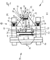
- the pressing tool part 1 shown is part of a pressing tool (not explicitly numbered) used in a device 2 for eliminating flatness errors (not shown) on a flat semi-finished product 3 and corresponds to a further pressing tool part 4, which in this exemplary embodiment is represented by a Press table 5 of the device 2 is embodied.
- the press tool part 1 on the other hand, is held on a press ram 6 that can be moved with respect to the press table 5 and thus above the flat semi-finished product 3 so that the press tool part 1 can be moved in the pressing direction 7 in order to be able to exert pressing forces on the flat semi-finished product 3 placed on the press table 5 .
- the press table 5 is stationary and the press ram 6 is displaceable on two stand elements 8 and 9 of a machine frame 10 of the device 2.
- the press ram 6 has an articulated connection 11 by means of which two press ram areas 12 and 13 are articulated to one another, as a result of which the press ram 6 has a higher flexibility.
- the device 2 for eliminating flatness errors on the flat semi-finished product 3 is designed as a straightening press 15, which is used exclusively for the purpose of removing flatness errors on the flat semi-finished product 3.
- the pressing tool part 1 also and preferably exclusively serves to eliminate flatness errors on the flat semi-finished product 3. More precisely, the pressing tool part 1 is a flatness error straightening press tool part (not numbered separately).
- the pressing tool part 1 has on its underside 20 a pressing surface area 21 which forms a pressing surface 22 facing the flat semi-finished product 3.
- the pressing surface area 21 of the pressing tool part 1 has a pressing surface width 23 which is greater than the width 24 of the flat semi-finished product 3.
- the pressing tool part 1 is divided into two separate partial halves 26 and 27 by a material weakening 25, with an elastically bendable bending bridge area 28 of the pressing tool part 1 being present next to or in this embodiment below the material weakening 25, by means of which the two partial halves 26 and 27 are physically are connected to each other.
- the press tool part 1 is thus constructed in such a way that the material weakening 25 formulates a dividing plane 30, the first partial half 26 lying on a first side 31 of the dividing plane 30 and the second partial half 27 being arranged on a second side 32 of the dividing plane 30 opposite the first side 31 is.
- the material weakening 25 is thus limited by three inner sides of the pressing tool part 1, namely by sides (not additionally numbered) of the two partial halves 26 and 27 and by the elastically bendable bending bridge area 28.
- the material weakening 25 extends upwards from the elastically bendable bending bridge area 28 along this dividing plane 30.
- the pressing tool part 1 experiences a structural weakening, as a result of which it can be deformed or bent more easily.
- Deformation forces or bending forces in this regard are applied as working forces by an actuator 35, which for this purpose is operatively connected to the two partial halves 26 and 27.
- the press tool part 1 is built quite high by a split support frame part 36 which is integrally connected to the press tool part 1, which has the advantage that the actuator 35 can be arranged further up and thus spaced from the press ram 6.
- the divided support frame part 36 consists of a first frame part half 37, which is rigidly connected to the first part half 26, and a second frame part half 38 which is rigidly operatively connected to the second part half 27.
- the first frame part half 37 is thus an extension of the first part half 26 of the press tool part 1 and the second frame part half 38 is a corresponding extension of the second part half 27 of the press tool part 1.
- the actuator 35 is already very well integrated in the press tool part 1.
- the actuator 35 is arranged further away from the elastically bendable bending bridge area 28 by means of the divided support frame part 36, the lever ratios with regard to the actuator 35 and the elastically bendable bending bridge area 28 are improved, so that the actuator 35 has to generate fewer workers in order to to be able to set a desired deformation on the pressing tool part 1.
- the actuator 35 can also be designed to be smaller, since it has to employ less manpower in order to deform the pressing tool part 1. This is also supported by the articulated press ram 6, since this can deform and in particular bend as a function of the work force to be applied by the actuator 35.
- the actuator 35 is attached directly to the partial halves 26 and 27 . In this way, the settings with regard to a deformation or bending of the pressing tool part 1 can be made even more precisely, since the workers applied by the actuator 35 can ideally be introduced without play, in particular into the elastically bendable bending bridge area 28.
- the actuator 35 is moved apart or into one another or shifted or shortened in accordance with the direction of movement 39 running perpendicular to the dividing plane 30, whereby the two frame halves 37 and 38 or the two partial halves 26 and 27 the elastically bendable bending bridge area 28 are moved around.
- the actuator 35 is integrated into the divided support frame part 36 in such a way that the separate halves 26 and 27 are operatively connected to one another by means of the actuator 35.
- the actuator 35 is designed as a hydraulic cylinder unit 40, the cylinder chamber 41 of the Hydraulic cylinder unit 40 is formed directly from the first frame part half 37 of the divided support frame part 36.
- the corresponding piston element 42 of the hydraulic cylinder unit 40 is placed with its piston head 43 in the cylinder chamber 41 and is thus fastened to the first frame part half 37.
- the piston element 42 of the hydraulic cylinder unit 40 is fastened to the second frame part half 38 with its piston rod 44.
- the actuator 35 or the hydraulic cylinder unit 40 is supplied with a hydraulic fluid by means of a correspondingly configured fluid connection device 45, the fluid connection device 45 comprising at least one input and / or output connection 46 (numbered only as an example) and at least one fluid line 47 in order to to be able to ensure a fluidic connection between the cylinder chamber 41 and a supply unit (not shown).
- a first end 48 of the piston element 42 is interactively connected to the first partial half 27 of the pressing tool part 1 and a second end 49 of the piston element 42 is interactively connected to the second half 27 of the pressing tool part 1.
- edge waves (not shown) in the flat semi-finished product 3 can be effectively prevented, since the present device 2 in this embodiment has a cumulative tilting device 50 with two further hydraulic cylinder units 51 and 52 arranged between the press ram 6 and the column elements 8 and 9 of the machine frame 10 .
- the press ram 6 and in particular the press tool part 1 are mounted on the press ram 6 or on the machine frame 10 so that they can be tilted about a tilt axis 53 running parallel to the press surface 22, whereby the interaction between the Press tool part 1 and the flat semi-finished product 3 can be expanded by further setting options.
- the other two hydraulic cylinder units 51 and 52 each have hydraulic connections 54 (numbered only by way of example), via which they can be fed with a hydraulic fluid.
- the pressing tool part 101 is even more compact, with the pressing tool part 101 being divided into two partial halves 126 and 127 by the material weakening 125.
- the one in the Figure 3 Another embodiment shown has another press tool part 201 means 255 for influencing the rigidity of the press tool part 201, which can be provided cumulatively or alternatively.
- the means 255 for influencing the rigidity comprise two pressure chambers 256 and 257 for receiving one Hydraulic fluid which are directly integrated in the press tool part 201; namely in the immediate vicinity of the pressing surface area 221 realizing the pressing surface 222.
- the means 255 for influencing the rigidity also comprise two delivery devices 258 and 259, the first delivery device 258 fluidically by means of a first fluid connection device 245A on the first pressure chamber 256 and the second delivery device 259 by means of a fluid connection device 245B on the second pressure chamber 257 are connected, so that each of the two pressure chambers 256 and 257 can be controlled independently of one another, which in turn can increase the variety of differently stiff areas on the pressing tool part 201.
- Each of the two delivery devices 258 and 259 has at least one hydraulic fluid reservoir 260 (only numbered as an example), a delivery pump 261 (only numbered as an example) and a control valve 262 (only numbered as an example), so that the respective pressure in the pressure chambers 256 or 257 can be set almost arbitrarily.
- the rigidity of the pressing tool part 1 can be set differently over its pressing surface width 223.
- the further press tool part 301 taught also has means 355 for influencing the rigidity of the press tool part 301, which has further hydraulic cylinder units 364 and 365 arranged within the press tool part 301 in order to manipulate the rigidity of the press tool part 301.
- cylinder chambers 366 (only numbered as an example) are designed by the further hydraulic cylinder units 364 and 365 directly by the pressing tool part 301 itself, with piston elements 367 located in the cylinder chambers 366 (only numbered as an example). by applying hydraulic pressure in the pressing direction 7 (see also Figure 1 ) to be able to set the pressures prevailing in the cylinder chambers 366.
- the means 355 for influencing the rigidity of the pressing tool part 301 comprise correspondingly designed fluid connection devices 345 (only numbered as an example).
- the illustrated press tool part 401 again comprises means 455 implemented differently for influencing the rigidity of the press tool part 401, two wedge mechanics units 470 and 471, which are each arranged in a cavity 473 or 474 embodied by the press tool part 401.
- Each of the two wedge mechanism units 470 and 471 has a wedge element 475 (only numbered as an example) arranged in a stationary manner in the press tool part 401 and a wedge element 476 that can be displaced in relation to this (only numbered as an example), the wedge elements 475 and 476 interacting with one another interacting with one another in such a way that that the rigidity can be varied depending on the position of the displaceable wedge element 476 in relation to the stationary wedge element 475.
- the stationary wedge element 475 and the wedge element 476 that can be displaced for this purpose each form a wedge element pair 477 (only numbered as an example) of the means 455 for influencing the rigidity of the press tool part 401, which are each placed in the associated cavity 473 or 474 within the press tool part 401.
- the respective displaceable wedge element 476 can be displaced parallel to the pressing surface 422 by a suitably designed but not further shown hydraulic device, so that a wall section 478 (only numbered as an example) facing the pressing surface 422 of the respective cavity 473 or 474 of the pressing tool part 401 more or less strong can be supported, whereby the rigidity of the pressing tool part 401 can in turn be changed.
- the means for influencing the rigidity can of course also be used to cumulatively or alternatively change the contour of the press tool part.
- two hold-down devices 580 and 581 for additionally holding down the flat semi-finished product 3 (see also Figure 1 ) in the lateral edge regions 582 and 583 of the pressing tool part 501, these holding-down devices 580 and 581 being placed laterally next to the actual pressing surface 522 in this exemplary embodiment.
- the two hold-down devices 580 and 581 move perpendicular to the pressing surface 522 and are moved out of or towards the pressing tool part 501 parallel to the pressing direction 7.
- the hold-down devices 580 and 581 can be addressed via a suitably designed hydraulic device, which is not shown in any further detail.
- the pressing tool part 601 comprises a travel device 685, by means of which the pressing tool part 601 can be moved from one to the other in the device 2 (see, for example, FIG Figure 1 ) mounted press tool (not shown) formulated working position 686 can be shifted into a change position 687 positioned next to the press tool or the device 2 in order to be able to be exchanged for another press tool part 1, 101, 201, 301, 401, 501, etc. .
- the driving device 685 here comprises four wheels 688 (only numbered by way of example), which are held on the underside 620 of the pressing tool part 601.
- the pressing surface 622 is arranged between two pairs of wheels (not numbered).
- the driving device 685 also includes a roadway cross member 689 on which the wheels 688 roll in a guided manner.
Claims (24)
- Partie d'un outil de compression (1 ; 101 ; 201 ; 301 ; 401 ; 501 ; 601) destinée à supprimer un défaut de planéité d'un produit semi-fini de forme plate (3), qui comprend une surface de compression (22, 222 ; 422 ; 522 ; 622) tournée vers le produit semi-fini de forme plate (3), caractérisée en ce que la partie de l'outil de compression (1 ; 101 ; 201 ; 301 ; 401 ; 501 ; 601) présente des moitiés de partie (26, 27 ; 126, 127) séparées les unes des autres par l'intermédiaire d'un affaiblissement de matière (25; 125), moitiés qui sont reliées de manière fonctionnelle d'une part les unes aux autres au moyen d'une zone de pliage formant pont (28; 128) de la partie de l'outil de compression (1 ; 101 ; 201 ; 301 ; 401 ; 501 ; 601), qui manifeste une flexibilité de type élastique, et d'autre part, de manière respective, à un actionneur commun (35 ; 135), dans le but de soumettre la surface de compression (22, 222; 422; 522; 622) de la partie de l'outil de compression (1 ; 101 ; 201 ; 301 ; 401 ; 501 ; 601) à une déformation de type élastique en fonction du défaut de planéité.
- Partie d'un outil de compression (1 ; 101 ; 201 ; 301 ; 401 ; 501 ; 601) selon la revendication 1, caractérisée en ce que l'actionneur commun (35; 135) est fixé de manière directe aux moitiés de partie (26, 27; 126, 127).
- Partie d'un outil de compression (1 ; 101 ; 201 ; 301 ; 401 ; 501 ; 601) selon la revendication 1 ou 2, caractérisée en ce que les moitiés de partie séparées les unes des autres (26, 27 ; 126, 127) sont reliées les unes aux autres de manière fonctionnelle au moyen de l'actionneur commun (35 ; 135).
- Partie d'un outil de compression (1 ; 101 ; 201 ; 301 ; 401 ; 501 ; 601) selon l'une quelconque des revendications 1 à 3, caractérisée en ce que l'actionneur commun (35; 135) est maintenu, respectivement est supporté par la partie de l'outil de compression (1 ; 101 ; 201 ; 301 ; 401 ; 501 ; 601).
- Partie d'un outil de compression (1 ; 101 ; 201 ; 301 ; 401 ; 501 ; 601) selon l'une quelconque des revendications 1 à 4, caractérisée en ce que l'actionneur commun (35 ; 135) est intégré dans la partie de l'outil de compression (1 ; 101 ; 201 ; 301 ; 401 ; 501 ; 601).
- Partie d'un outil de compression (1 ; 101 ; 201 ; 301 ; 401 ; 501 ; 601) selon l'une quelconque des revendications 1 à 5, caractérisée en ce que l'actionneur commun (35 ; 135) comprend une unité sous la forme d'un cylindre hydraulique (40; 140).
- Partie d'un outil de compression (1 ; 101 ; 201 ; 301 ; 401 ; 501 ; 601) selon l'une quelconque des revendications 1 à 6, caractérisée en ce que l'actionneur commun (35 ; 135) comprend une chambre faisant office de cylindre (41) qui est réalisée par l'intermédiaire d'une des moitiés de partie (26, 27; 126, 127) de la partie de l'outil de compression (1; 101; 201; 301; 401; 501; 601).
- Partie d'un outil de compression (1 ; 101 ; 201 ; 301 ; 401 ; 501 ; 601) selon l'une quelconque des revendications 1 à 7, caractérisée en ce que l'actionneur commun (35 ; 135) comprend un élément (42) faisant office de piston ; dans laquelle une première extrémité (48) de l'élément faisant office de piston (42) de la partie de l'outil de compression (1 ; 101 ; 201 ; 301 ; 401 ; 501 ; 601) et une deuxième extrémité (49) de l'élément faisant office de piston (42) sont reliées en interaction, la première à la première moitié de partie (26; 16) de la partie de l'outil de compression (1 ; 101 ; 201 ; 301 ; 401 ; 501 ; 601) et la deuxième à la deuxième moitié de partie (27; 127) de la partie de l'outil de compression (1; 101; 201; 301; 401; 501; 601).
- Partie d'un outil de compression (1 ; 101 ; 201 ; 301 ; 401 ; 501 ; 601) selon l'une quelconque des revendications 1 à 8, caractérisée en ce que l'actionneur commun (35 ; 135) est disposé, au moyen de la partie de l'outil de compression (1; 101; 201; 301 ; 401 ; 501 ; 601) contre un coulisseau de compression (6) d'un dispositif (2), apte à se déplacer, qui est destiné à supprimer des défauts de planéité sur des produits semi-finis (3) de forme plate ou contre une table de compression (5) du dispositif en question.
- Partie d'un outil de compression (1 ; 101 ; 201 ; 301 ; 401 ; 501 ; 601) selon l'une quelconque des revendications 1 à 9, caractérisée en ce que la partie de l'outil de compression (1 ; 101 ; 201 ; 301 ; 401 ; 501 ; 601) comprend un mécanisme de raccordement à un fluide (45) pour une exploitation de l'actionneur commun (35; 135) à l'aide d'un fluide.
- Partie d'un outil de compression (1 ; 101 ; 201 ; 301 ; 401 ; 501 ; 601) selon l'une quelconque des revendications 1 à 10, caractérisée en ce que la partie de l'outil de compression (1) comprend un élément en plusieurs parties (36) faisant office de cadre de support, dans lequel est intégré l'actionneur commun (35 ;135).
- Partie d'un outil de compression (1 ; 101 ; 201 ; 301 ; 401 ; 501 ; 601) selon l'une quelconque des revendications 1 à 11, caractérisée en ce que la partie de l'outil de compression (1) est subdivisée en deux moitiés de partie (26, 27; 16, 127) de grandeurs égales par l'intermédiaire de l'affaiblissement de matière (25; 125).
- Partie d'un outil de compression (1 ; 101 ; 201; 301; 401; 501 ; 601) selon l'une quelconque des revendications 1 à 12, caractérisée en ce que l'affaiblissement de matière (25; 125) s'étend à partir de la zone de pliage formant pont (28 ; 128), qui manifeste une flexibilité de type élastique, le long d'un plan (30) qui s'étend en direction perpendiculaire par rapport à la surface de compression (22, 222 ; 422 ; 522 ; 622).
- Partie d'un outil de compression (1 ; 101 ; 201 ; 301 ; 401 ; 501 ; 601) selon l'une quelconque des revendications 1 à 13, caractérisée en ce que les moitiés de partie (26, 27 ; 16, 127) de la partie de l'outil de compression (1 ; 101 ; 201 ; 301 ; 401 ; 501 ; 601) sont maintenues en mobilité contre un coulisseau de compression (6).
- Partie d'un outil de compression (1 ; 101 ; 201 ; 301 ; 401 ; 501 ; 601) selon l'une quelconque des revendications 1 à 14, caractérisée en ce que la partie de l'outil de compression (1 ; 101 ; 201 ; 301 ; 401 ; 501 ; 601) comprend des moyens (255; 355; 455) qui sont destinés à influencer la rigidité de la partie de l'outil de compression (1 ; 101 ; 201 ; 301 ; 401 ; 501 ; 601).
- Partie d'un outil de compression (1 ; 101 ; 201; 301; 401; 501 ; 601) selon la revendication 15, caractérisée en ce que les moyens (255) qui sont destinés à influencer la rigidité de la partie de l'outil de compression (201) comprennent au moins une chambre de pression (256, 257) qui est intégrée dans la partie de l'outil de compression (201).
- Partie d'un outil de compression (1 ; 101 ; 201 ; 301 ; 401 ; 501 ; 601) selon la revendication 15 ou 16, caractérisée en ce que les moyens (355) qui sont destinés à influencer la rigidité de la partie de l'outil de compression (301) comprennent au moins une unité supplémentaire sous la forme d'un cylindre hydraulique (364, 365) qui est intégrée dans la partie de l'outil de compression (301).
- Partie d'un outil de compression (1 ; 101 ; 201; 301; 401; 501 ; 601) selon la revendication 17, caractérisée en ce que les moyens (455) qui sont destinés à influencer la rigidité de la partie de l'outil de compression (401) comprennent au moins une unité faisant office de mécanisme sous la forme d'une clavette (470, 471) qui est intégrée dans la partie de l'outil de compression (401) ; dans laquelle l'unité faisant office de mécanisme sous la forme d'une clavette (470, 471) présente au moins un élément (476) sous la forme d'une clavette qui peut se déplacer par rapport à la partie de l'outil de compression (401).
- Partie d'un outil de compression (1 ; 101 ; 201; 301; 401; 501 ; 601) selon l'une quelconque des revendications 1 à 18, caractérisée en ce que la partie de l'outil de compression (501) comprend des serre-flans (580, 581) qui sont destinés au maintien du produit semi-fini de forme plate (3), qui sont mobiles en exécutant un mouvement de translation en direction perpendiculaire par rapport à la surface de compression (522).
- Partie d'un outil de compression (1 ; 101; 201; 301; 401; 501 ; 601) selon l'une quelconque des revendications 1 à 19, caractérisée en ce que la partie de l'outil de compression (601) comprend un mécanisme de déplacement (685) au moyen duquel elle peut être déplacée à partir d'une position de travail (686) formulée par un outil de compression (601) pour prendre une position d'échange (687) disposée à côté de l'outil de compression (601).
- Partie d'un outil de compression (1 ; 101 ; 201 ; 301 ; 401 ; 501 ; 601) selon l'une quelconque des revendications 1 à 20, caractérisée en ce que la surface de compression (22, 222 ; 422 ; 622) de la partie de l'outil de compression (1) est réalisée au moyen d'une zone (21) sous la forme d'une surface de compression, qui présente une largeur de surface de compression (23) qui est supérieure à la largeur (24) du produit semi-fini de forme plate (3).
- Dispositif (2) destiné à éliminer des défauts de planéité sur des produits semi-finis de forme plate (3), en particulier presse de dressage (15) qui comprend un bâti de machine (10) contre lequel est monté un coulisseau de compression (6) qui peut être déplacé dans la direction de compression (7) par rapport à une table de compression (5), et qui comprend un outil de compression comprenant au moins une partie d'un outil de compression (1 ; 101 ; 201 ; 301 ; 401 ; 501 ; 601) présentant une surface de compression (22, 222; 422; 522; 622), partie au moyen de laquelle on peut éliminer des défauts de planéité sur le produit semi-fini de forme plate (3), caractérisé en ce que le dispositif (2) présente une partie d'un outil de compression (1 ; 101 ; 201 ; 301 ; 401 ; 501 ; 601) selon l'une quelconque des revendications précédentes.
- Dispositif (2) selon la revendication 22, caractérisé en ce que le dispositif (2) présente un mécanisme de basculement (50) au moyen duquel est montée une partie d'un outil de compression (1 ; 101 ; 201 ; 301 ; 401 ; 501 ; 601) contre le coulisseau de compression (6) ou contre le bâti de machine (10) de manière à pouvoir basculer autour d'un axe de basculement (53) qui s'étend parallèlement à la surface de compression (22, 222; 422; 522; 622).
- Dispositif (2) selon la revendication 23, caractérisé en ce que le mécanisme de basculement (50) comprend au moins une, de préférence deux unités (51, 52) faisant office de cylindre(s) hydraulique(s) qui déploient leur activité entre le coulisseau de compression (6) et le bâti de machine (10), dans le but de basculer le coulisseau de compression (6) autour de l'axe de basculement (53).
Applications Claiming Priority (2)
| Application Number | Priority Date | Filing Date | Title |
|---|---|---|---|
| DE102014226519.3A DE102014226519A1 (de) | 2014-12-19 | 2014-12-19 | Presswerkzeugteil und Vorrichtung zum Beseitigen von Planheitsfehlern an flächigen Halbzeugen |
| PCT/EP2015/078276 WO2016096411A1 (fr) | 2014-12-19 | 2015-12-02 | Pièce d'outil de moulage par compression et dispositif d'élimination des défauts de planéité sur des demi-produits plats |
Publications (2)
| Publication Number | Publication Date |
|---|---|
| EP3233321A1 EP3233321A1 (fr) | 2017-10-25 |
| EP3233321B1 true EP3233321B1 (fr) | 2021-02-17 |
Family
ID=54780290
Family Applications (1)
| Application Number | Title | Priority Date | Filing Date |
|---|---|---|---|
| EP15804424.8A Active EP3233321B1 (fr) | 2014-12-19 | 2015-12-02 | Pièce d'outil de moulage par compression et dispositif d'élimination des défauts de planéité sur des demi-produits plats |
Country Status (8)
| Country | Link |
|---|---|
| US (1) | US20180001361A1 (fr) |
| EP (1) | EP3233321B1 (fr) |
| JP (1) | JP6413020B2 (fr) |
| KR (1) | KR101978258B1 (fr) |
| CN (1) | CN107206450B (fr) |
| DE (1) | DE102014226519A1 (fr) |
| RU (1) | RU2677819C1 (fr) |
| WO (1) | WO2016096411A1 (fr) |
Families Citing this family (5)
| Publication number | Priority date | Publication date | Assignee | Title |
|---|---|---|---|---|
| DE102015219127A1 (de) | 2015-10-02 | 2017-04-06 | Sms Group Gmbh | Vorrichtung zum Richtpressen eines metallischen Flachproduktes |
| CN112743004A (zh) * | 2021-01-27 | 2021-05-04 | 史振军 | 一种输变电施工导线压接管校直器 |
| CN114011970B (zh) * | 2021-11-12 | 2024-01-05 | 东莞理工学院 | 一种带有弹性支撑装置的热成形模具凸模镶块 |
| CN114345993A (zh) * | 2021-12-29 | 2022-04-15 | 中船重工中南装备有限责任公司 | 一种大型矩形管校直装置及方法 |
| CN114345989A (zh) * | 2021-12-29 | 2022-04-15 | 中船重工中南装备有限责任公司 | 一种校型用带保护功能的压块组件 |
Citations (3)
| Publication number | Priority date | Publication date | Assignee | Title |
|---|---|---|---|---|
| DE4235971C1 (de) * | 1992-10-26 | 1994-04-07 | M & S Brugg Ag Brugg | Abkantpresse |
| FR2782942A1 (fr) * | 1998-09-09 | 2000-03-10 | Amada Europ Sa | Presse plieuse a tablier inferieur actif |
| US20100229622A1 (en) * | 2009-03-13 | 2010-09-16 | Amada Europe | Press brake for bending sheets |
Family Cites Families (23)
| Publication number | Priority date | Publication date | Assignee | Title |
|---|---|---|---|---|
| US2456856A (en) * | 1947-10-11 | 1948-12-21 | Cyril Bath Co | Bolster block |
| US3234774A (en) * | 1962-11-21 | 1966-02-15 | Du Pont | Compression pad |
| GB1021794A (en) * | 1962-12-11 | 1966-03-09 | Driam Sa | Method and apparatus for straightening laterally curved metal bands |
| JPS5216268Y2 (fr) * | 1974-09-30 | 1977-04-12 | ||
| US3965721A (en) * | 1975-02-24 | 1976-06-29 | Hurco Manufacturing Company, Inc. | Adjustable die holder |
| DE2541094A1 (de) * | 1975-09-15 | 1977-03-17 | Seiji Shiokawa | Pressvorrichtung |
| SU795617A1 (ru) * | 1977-12-26 | 1981-01-15 | Институт Электроники Ан Белорус-Ской Ccp | Способ правки листовых изделий |
| US4157027A (en) * | 1978-01-03 | 1979-06-05 | Archer Jimmy D | Spool straightening apparatus |
| SU995966A1 (ru) * | 1980-12-31 | 1983-02-15 | Предприятие П/Я Р-6877 | Штамп дл правки изделий |
| SU1269875A1 (ru) * | 1985-07-01 | 1986-11-15 | Предприятие П/Я Г-4361 | Пресс дл правки листового материала |
| JPH0890102A (ja) * | 1994-09-26 | 1996-04-09 | Mazda Motor Corp | プレス成形における金型の支持および交換装置 |
| JPH09300021A (ja) * | 1996-05-14 | 1997-11-25 | Toray Ind Inc | 金属板の歪み修正装置 |
| RU2090283C1 (ru) * | 1996-08-05 | 1997-09-20 | Акционерное общество открытого типа "УралЛУКтрубмаш" | Способ правки изделий и пресс для его осуществления |
| CA2336558C (fr) * | 2000-02-22 | 2005-02-01 | Honda Giken Kogyo Kabushiki Kaisha | Matrice et methode de fabrication de matrices |
| US6205830B1 (en) * | 2000-02-24 | 2001-03-27 | The Material Works, Ltd. | Method and apparatus for processing sheet metal |
| JP4568077B2 (ja) * | 2004-10-19 | 2010-10-27 | 新日本製鐵株式会社 | 形状凍結性に優れたプレス金型 |
| JP2007229753A (ja) * | 2006-02-28 | 2007-09-13 | Jfe Steel Kk | プレス矯正機およびプレス矯正方法 |
| WO2010061745A1 (fr) * | 2008-11-25 | 2010-06-03 | 住友金属工業株式会社 | Dispositif pour corriger une forme d'extrémité de tuyau d'un tuyau métallique uoe |
| DE102012204074A1 (de) * | 2012-03-15 | 2013-09-19 | Sms Siemag Ag | Vorrichtung zum Richten von Metallband |
| JP6036555B2 (ja) * | 2013-05-29 | 2016-11-30 | トヨタ紡織株式会社 | プレス金型 |
| CN203751039U (zh) * | 2014-01-21 | 2014-08-06 | 万世泰金属工业(昆山)有限公司 | 金属板局部调直设备 |
| CN104148446B (zh) * | 2014-07-30 | 2016-09-14 | 洛阳鹏起实业有限公司 | 一种利用石墨模具对变形钛合金铸件的矫正方法 |
| US9481026B2 (en) * | 2014-10-27 | 2016-11-01 | Tyco Electronics Corporation | Press device with adjustment mechanism |
-
2014
- 2014-12-19 DE DE102014226519.3A patent/DE102014226519A1/de not_active Withdrawn
-
2015
- 2015-12-02 EP EP15804424.8A patent/EP3233321B1/fr active Active
- 2015-12-02 WO PCT/EP2015/078276 patent/WO2016096411A1/fr active Application Filing
- 2015-12-02 KR KR1020177017788A patent/KR101978258B1/ko active IP Right Grant
- 2015-12-02 RU RU2017125497A patent/RU2677819C1/ru active
- 2015-12-02 CN CN201580074956.9A patent/CN107206450B/zh active Active
- 2015-12-02 JP JP2017532663A patent/JP6413020B2/ja active Active
- 2015-12-02 US US15/537,503 patent/US20180001361A1/en not_active Abandoned
Patent Citations (3)
| Publication number | Priority date | Publication date | Assignee | Title |
|---|---|---|---|---|
| DE4235971C1 (de) * | 1992-10-26 | 1994-04-07 | M & S Brugg Ag Brugg | Abkantpresse |
| FR2782942A1 (fr) * | 1998-09-09 | 2000-03-10 | Amada Europ Sa | Presse plieuse a tablier inferieur actif |
| US20100229622A1 (en) * | 2009-03-13 | 2010-09-16 | Amada Europe | Press brake for bending sheets |
Also Published As
| Publication number | Publication date |
|---|---|
| JP6413020B2 (ja) | 2018-10-24 |
| WO2016096411A1 (fr) | 2016-06-23 |
| RU2017125497A3 (fr) | 2019-01-23 |
| JP2017537796A (ja) | 2017-12-21 |
| RU2017125497A (ru) | 2019-01-23 |
| CN107206450A (zh) | 2017-09-26 |
| KR20170090460A (ko) | 2017-08-07 |
| US20180001361A1 (en) | 2018-01-04 |
| DE102014226519A1 (de) | 2016-06-23 |
| KR101978258B1 (ko) | 2019-05-14 |
| EP3233321A1 (fr) | 2017-10-25 |
| RU2677819C1 (ru) | 2019-01-21 |
| CN107206450B (zh) | 2019-03-08 |
Similar Documents
| Publication | Publication Date | Title |
|---|---|---|
| EP3233321B1 (fr) | Pièce d'outil de moulage par compression et dispositif d'élimination des défauts de planéité sur des demi-produits plats | |
| AT504640B1 (de) | Biegemaschine | |
| DE102005022052A1 (de) | Verfahren und Vorrichtung zum Richten länglicher Werkstücke | |
| DE19717472A1 (de) | Verfahren und Vorrichtung zum Profilbiegen mit modularen Biegestationen | |
| WO2015081359A1 (fr) | Machine à cintrer | |
| EP1793946A1 (fr) | Procede pour realiser une piece par cintrage | |
| EP2814627B1 (fr) | Presse à cintrer doté d'élément barre réglable | |
| EP2127772A2 (fr) | Dispositif de formage | |
| EP1731237B1 (fr) | Machine pour travailler de la tôle | |
| EP0330914A1 (fr) | Dispositif d'éjection des pièces hors des matrices dans une presse de formage | |
| EP3160726B1 (fr) | Presse à châssis en c, améliorée | |
| DE102005007712A1 (de) | Rollvorformen | |
| DE102005022043B3 (de) | Verfahren und Vorrichtung zum Richten eines länglichen Werkstückes | |
| DE102018211311A1 (de) | Erweiterte Regelung JCO-Formpresse | |
| EP1448323B1 (fr) | Dispositif de fabrication d'un tube | |
| EP0641265B1 (fr) | Machine a dresser | |
| DE102005021946A1 (de) | Verfahren und Vorrichtung zum Richten länglicher Werkstücke | |
| EP2809505B1 (fr) | Presse plieuse à bâti en forme de c | |
| WO2016071161A1 (fr) | Presse plieuse de tube | |
| DE2331754C3 (de) | Hydraulische Rohrbiegepresse | |
| EP2465695B1 (fr) | Procédé et dispositif destinés à comprimer un bloc de livre | |
| WO2017013099A1 (fr) | Installation et procédé destinés à l'élimination de défauts de planéité d'un produit plat métallique | |
| DE102020133419B4 (de) | Anordnung, Verfahren und Richteinheit zum Rundbiegen des Endbereichs mit den beiden Enden spitzgebogener Rohre mit einer 3-Walzen-Biegemaschine | |
| EP0879102B1 (fr) | Machine de cintrage circulaire des toles | |
| DE102008055780A1 (de) | Biegemaschine für Blechtafeln |
Legal Events
| Date | Code | Title | Description |
|---|---|---|---|
| STAA | Information on the status of an ep patent application or granted ep patent |
Free format text: STATUS: THE INTERNATIONAL PUBLICATION HAS BEEN MADE |
|
| PUAI | Public reference made under article 153(3) epc to a published international application that has entered the european phase |
Free format text: ORIGINAL CODE: 0009012 |
|
| STAA | Information on the status of an ep patent application or granted ep patent |
Free format text: STATUS: REQUEST FOR EXAMINATION WAS MADE |
|
| 17P | Request for examination filed |
Effective date: 20170719 |
|
| AK | Designated contracting states |
Kind code of ref document: A1 Designated state(s): AL AT BE BG CH CY CZ DE DK EE ES FI FR GB GR HR HU IE IS IT LI LT LU LV MC MK MT NL NO PL PT RO RS SE SI SK SM TR |
|
| AX | Request for extension of the european patent |
Extension state: BA ME |
|
| STAA | Information on the status of an ep patent application or granted ep patent |
Free format text: STATUS: EXAMINATION IS IN PROGRESS |
|
| 17Q | First examination report despatched |
Effective date: 20180219 |
|
| DAV | Request for validation of the european patent (deleted) | ||
| DAX | Request for extension of the european patent (deleted) | ||
| GRAP | Despatch of communication of intention to grant a patent |
Free format text: ORIGINAL CODE: EPIDOSNIGR1 |
|
| STAA | Information on the status of an ep patent application or granted ep patent |
Free format text: STATUS: GRANT OF PATENT IS INTENDED |
|
| INTG | Intention to grant announced |
Effective date: 20200722 |
|
| GRAS | Grant fee paid |
Free format text: ORIGINAL CODE: EPIDOSNIGR3 |
|
| GRAA | (expected) grant |
Free format text: ORIGINAL CODE: 0009210 |
|
| STAA | Information on the status of an ep patent application or granted ep patent |
Free format text: STATUS: THE PATENT HAS BEEN GRANTED |
|
| AK | Designated contracting states |
Kind code of ref document: B1 Designated state(s): AL AT BE BG CH CY CZ DE DK EE ES FI FR GB GR HR HU IE IS IT LI LT LU LV MC MK MT NL NO PL PT RO RS SE SI SK SM TR |
|
| REG | Reference to a national code |
Ref country code: GB Ref legal event code: FG4D Free format text: NOT ENGLISH |
|
| REG | Reference to a national code |
Ref country code: CH Ref legal event code: EP |
|
| REG | Reference to a national code |
Ref country code: DE Ref legal event code: R096 Ref document number: 502015014267 Country of ref document: DE |
|
| REG | Reference to a national code |
Ref country code: AT Ref legal event code: REF Ref document number: 1360804 Country of ref document: AT Kind code of ref document: T Effective date: 20210315 |
|
| REG | Reference to a national code |
Ref country code: IE Ref legal event code: FG4D Free format text: LANGUAGE OF EP DOCUMENT: GERMAN |
|
| REG | Reference to a national code |
Ref country code: LT Ref legal event code: MG9D |
|
| REG | Reference to a national code |
Ref country code: NL Ref legal event code: MP Effective date: 20210217 |
|
| PG25 | Lapsed in a contracting state [announced via postgrant information from national office to epo] |
Ref country code: LT Free format text: LAPSE BECAUSE OF FAILURE TO SUBMIT A TRANSLATION OF THE DESCRIPTION OR TO PAY THE FEE WITHIN THE PRESCRIBED TIME-LIMIT Effective date: 20210217 Ref country code: PT Free format text: LAPSE BECAUSE OF FAILURE TO SUBMIT A TRANSLATION OF THE DESCRIPTION OR TO PAY THE FEE WITHIN THE PRESCRIBED TIME-LIMIT Effective date: 20210617 Ref country code: NO Free format text: LAPSE BECAUSE OF FAILURE TO SUBMIT A TRANSLATION OF THE DESCRIPTION OR TO PAY THE FEE WITHIN THE PRESCRIBED TIME-LIMIT Effective date: 20210517 Ref country code: HR Free format text: LAPSE BECAUSE OF FAILURE TO SUBMIT A TRANSLATION OF THE DESCRIPTION OR TO PAY THE FEE WITHIN THE PRESCRIBED TIME-LIMIT Effective date: 20210217 Ref country code: GR Free format text: LAPSE BECAUSE OF FAILURE TO SUBMIT A TRANSLATION OF THE DESCRIPTION OR TO PAY THE FEE WITHIN THE PRESCRIBED TIME-LIMIT Effective date: 20210518 Ref country code: FI Free format text: LAPSE BECAUSE OF FAILURE TO SUBMIT A TRANSLATION OF THE DESCRIPTION OR TO PAY THE FEE WITHIN THE PRESCRIBED TIME-LIMIT Effective date: 20210217 Ref country code: BG Free format text: LAPSE BECAUSE OF FAILURE TO SUBMIT A TRANSLATION OF THE DESCRIPTION OR TO PAY THE FEE WITHIN THE PRESCRIBED TIME-LIMIT Effective date: 20210517 |
|
| PG25 | Lapsed in a contracting state [announced via postgrant information from national office to epo] |
Ref country code: SE Free format text: LAPSE BECAUSE OF FAILURE TO SUBMIT A TRANSLATION OF THE DESCRIPTION OR TO PAY THE FEE WITHIN THE PRESCRIBED TIME-LIMIT Effective date: 20210217 Ref country code: PL Free format text: LAPSE BECAUSE OF FAILURE TO SUBMIT A TRANSLATION OF THE DESCRIPTION OR TO PAY THE FEE WITHIN THE PRESCRIBED TIME-LIMIT Effective date: 20210217 Ref country code: LV Free format text: LAPSE BECAUSE OF FAILURE TO SUBMIT A TRANSLATION OF THE DESCRIPTION OR TO PAY THE FEE WITHIN THE PRESCRIBED TIME-LIMIT Effective date: 20210217 Ref country code: NL Free format text: LAPSE BECAUSE OF FAILURE TO SUBMIT A TRANSLATION OF THE DESCRIPTION OR TO PAY THE FEE WITHIN THE PRESCRIBED TIME-LIMIT Effective date: 20210217 Ref country code: RS Free format text: LAPSE BECAUSE OF FAILURE TO SUBMIT A TRANSLATION OF THE DESCRIPTION OR TO PAY THE FEE WITHIN THE PRESCRIBED TIME-LIMIT Effective date: 20210217 |
|
| PG25 | Lapsed in a contracting state [announced via postgrant information from national office to epo] |
Ref country code: IS Free format text: LAPSE BECAUSE OF FAILURE TO SUBMIT A TRANSLATION OF THE DESCRIPTION OR TO PAY THE FEE WITHIN THE PRESCRIBED TIME-LIMIT Effective date: 20210617 |
|
| PG25 | Lapsed in a contracting state [announced via postgrant information from national office to epo] |
Ref country code: CZ Free format text: LAPSE BECAUSE OF FAILURE TO SUBMIT A TRANSLATION OF THE DESCRIPTION OR TO PAY THE FEE WITHIN THE PRESCRIBED TIME-LIMIT Effective date: 20210217 Ref country code: EE Free format text: LAPSE BECAUSE OF FAILURE TO SUBMIT A TRANSLATION OF THE DESCRIPTION OR TO PAY THE FEE WITHIN THE PRESCRIBED TIME-LIMIT Effective date: 20210217 Ref country code: SM Free format text: LAPSE BECAUSE OF FAILURE TO SUBMIT A TRANSLATION OF THE DESCRIPTION OR TO PAY THE FEE WITHIN THE PRESCRIBED TIME-LIMIT Effective date: 20210217 |
|
| REG | Reference to a national code |
Ref country code: DE Ref legal event code: R097 Ref document number: 502015014267 Country of ref document: DE |
|
| PG25 | Lapsed in a contracting state [announced via postgrant information from national office to epo] |
Ref country code: SK Free format text: LAPSE BECAUSE OF FAILURE TO SUBMIT A TRANSLATION OF THE DESCRIPTION OR TO PAY THE FEE WITHIN THE PRESCRIBED TIME-LIMIT Effective date: 20210217 Ref country code: RO Free format text: LAPSE BECAUSE OF FAILURE TO SUBMIT A TRANSLATION OF THE DESCRIPTION OR TO PAY THE FEE WITHIN THE PRESCRIBED TIME-LIMIT Effective date: 20210217 Ref country code: DK Free format text: LAPSE BECAUSE OF FAILURE TO SUBMIT A TRANSLATION OF THE DESCRIPTION OR TO PAY THE FEE WITHIN THE PRESCRIBED TIME-LIMIT Effective date: 20210217 |
|
| PLBE | No opposition filed within time limit |
Free format text: ORIGINAL CODE: 0009261 |
|
| STAA | Information on the status of an ep patent application or granted ep patent |
Free format text: STATUS: NO OPPOSITION FILED WITHIN TIME LIMIT |
|
| 26N | No opposition filed |
Effective date: 20211118 |
|
| PG25 | Lapsed in a contracting state [announced via postgrant information from national office to epo] |
Ref country code: AL Free format text: LAPSE BECAUSE OF FAILURE TO SUBMIT A TRANSLATION OF THE DESCRIPTION OR TO PAY THE FEE WITHIN THE PRESCRIBED TIME-LIMIT Effective date: 20210217 Ref country code: ES Free format text: LAPSE BECAUSE OF FAILURE TO SUBMIT A TRANSLATION OF THE DESCRIPTION OR TO PAY THE FEE WITHIN THE PRESCRIBED TIME-LIMIT Effective date: 20210217 |
|
| PG25 | Lapsed in a contracting state [announced via postgrant information from national office to epo] |
Ref country code: SI Free format text: LAPSE BECAUSE OF FAILURE TO SUBMIT A TRANSLATION OF THE DESCRIPTION OR TO PAY THE FEE WITHIN THE PRESCRIBED TIME-LIMIT Effective date: 20210217 |
|
| PG25 | Lapsed in a contracting state [announced via postgrant information from national office to epo] |
Ref country code: IS Free format text: LAPSE BECAUSE OF FAILURE TO SUBMIT A TRANSLATION OF THE DESCRIPTION OR TO PAY THE FEE WITHIN THE PRESCRIBED TIME-LIMIT Effective date: 20210617 |
|
| PG25 | Lapsed in a contracting state [announced via postgrant information from national office to epo] |
Ref country code: MC Free format text: LAPSE BECAUSE OF FAILURE TO SUBMIT A TRANSLATION OF THE DESCRIPTION OR TO PAY THE FEE WITHIN THE PRESCRIBED TIME-LIMIT Effective date: 20210217 |
|
| REG | Reference to a national code |
Ref country code: CH Ref legal event code: PL |
|
| REG | Reference to a national code |
Ref country code: BE Ref legal event code: MM Effective date: 20211231 |
|
| PG25 | Lapsed in a contracting state [announced via postgrant information from national office to epo] |
Ref country code: LU Free format text: LAPSE BECAUSE OF NON-PAYMENT OF DUE FEES Effective date: 20211202 Ref country code: IE Free format text: LAPSE BECAUSE OF NON-PAYMENT OF DUE FEES Effective date: 20211202 |
|
| PG25 | Lapsed in a contracting state [announced via postgrant information from national office to epo] |
Ref country code: FR Free format text: LAPSE BECAUSE OF NON-PAYMENT OF DUE FEES Effective date: 20211231 Ref country code: BE Free format text: LAPSE BECAUSE OF NON-PAYMENT OF DUE FEES Effective date: 20211231 |
|
| PG25 | Lapsed in a contracting state [announced via postgrant information from national office to epo] |
Ref country code: LI Free format text: LAPSE BECAUSE OF NON-PAYMENT OF DUE FEES Effective date: 20211231 Ref country code: CH Free format text: LAPSE BECAUSE OF NON-PAYMENT OF DUE FEES Effective date: 20211231 |
|
| PG25 | Lapsed in a contracting state [announced via postgrant information from national office to epo] |
Ref country code: HU Free format text: LAPSE BECAUSE OF FAILURE TO SUBMIT A TRANSLATION OF THE DESCRIPTION OR TO PAY THE FEE WITHIN THE PRESCRIBED TIME-LIMIT; INVALID AB INITIO Effective date: 20151202 |
|
| PG25 | Lapsed in a contracting state [announced via postgrant information from national office to epo] |
Ref country code: CY Free format text: LAPSE BECAUSE OF FAILURE TO SUBMIT A TRANSLATION OF THE DESCRIPTION OR TO PAY THE FEE WITHIN THE PRESCRIBED TIME-LIMIT Effective date: 20210217 |
|
| P01 | Opt-out of the competence of the unified patent court (upc) registered |
Effective date: 20230707 |
|
| PGFP | Annual fee paid to national office [announced via postgrant information from national office to epo] |
Ref country code: GB Payment date: 20231220 Year of fee payment: 9 |
|
| PGFP | Annual fee paid to national office [announced via postgrant information from national office to epo] |
Ref country code: IT Payment date: 20231228 Year of fee payment: 9 Ref country code: DE Payment date: 20231214 Year of fee payment: 9 Ref country code: AT Payment date: 20231221 Year of fee payment: 9 |