EP3232103A1 - Robinetterie de raccordement pour un véhicule de transports de produits pétroliers - Google Patents
Robinetterie de raccordement pour un véhicule de transports de produits pétroliers Download PDFInfo
- Publication number
- EP3232103A1 EP3232103A1 EP17163232.6A EP17163232A EP3232103A1 EP 3232103 A1 EP3232103 A1 EP 3232103A1 EP 17163232 A EP17163232 A EP 17163232A EP 3232103 A1 EP3232103 A1 EP 3232103A1
- Authority
- EP
- European Patent Office
- Prior art keywords
- valve
- axis
- housing
- connection fitting
- rotation
- Prior art date
- Legal status (The legal status is an assumption and is not a legal conclusion. Google has not performed a legal analysis and makes no representation as to the accuracy of the status listed.)
- Granted
Links
Images


Classifications
-
- B—PERFORMING OPERATIONS; TRANSPORTING
- B60—VEHICLES IN GENERAL
- B60P—VEHICLES ADAPTED FOR LOAD TRANSPORTATION OR TO TRANSPORT, TO CARRY, OR TO COMPRISE SPECIAL LOADS OR OBJECTS
- B60P3/00—Vehicles adapted to transport, to carry or to comprise special loads or objects
- B60P3/22—Tank vehicles
- B60P3/224—Tank vehicles comprising auxiliary devices, e.g. for unloading or level indicating
- B60P3/225—Adaptations for pumps or valves
-
- F—MECHANICAL ENGINEERING; LIGHTING; HEATING; WEAPONS; BLASTING
- F16—ENGINEERING ELEMENTS AND UNITS; GENERAL MEASURES FOR PRODUCING AND MAINTAINING EFFECTIVE FUNCTIONING OF MACHINES OR INSTALLATIONS; THERMAL INSULATION IN GENERAL
- F16K—VALVES; TAPS; COCKS; ACTUATING-FLOATS; DEVICES FOR VENTING OR AERATING
- F16K1/00—Lift valves or globe valves, i.e. cut-off apparatus with closure members having at least a component of their opening and closing motion perpendicular to the closing faces
- F16K1/16—Lift valves or globe valves, i.e. cut-off apparatus with closure members having at least a component of their opening and closing motion perpendicular to the closing faces with pivoted closure-members
- F16K1/18—Lift valves or globe valves, i.e. cut-off apparatus with closure members having at least a component of their opening and closing motion perpendicular to the closing faces with pivoted closure-members with pivoted discs or flaps
- F16K1/22—Lift valves or globe valves, i.e. cut-off apparatus with closure members having at least a component of their opening and closing motion perpendicular to the closing faces with pivoted closure-members with pivoted discs or flaps with axis of rotation crossing the valve member, e.g. butterfly valves
- F16K1/221—Lift valves or globe valves, i.e. cut-off apparatus with closure members having at least a component of their opening and closing motion perpendicular to the closing faces with pivoted closure-members with pivoted discs or flaps with axis of rotation crossing the valve member, e.g. butterfly valves specially adapted operating means therefor
-
- F—MECHANICAL ENGINEERING; LIGHTING; HEATING; WEAPONS; BLASTING
- F16—ENGINEERING ELEMENTS AND UNITS; GENERAL MEASURES FOR PRODUCING AND MAINTAINING EFFECTIVE FUNCTIONING OF MACHINES OR INSTALLATIONS; THERMAL INSULATION IN GENERAL
- F16K—VALVES; TAPS; COCKS; ACTUATING-FLOATS; DEVICES FOR VENTING OR AERATING
- F16K1/00—Lift valves or globe valves, i.e. cut-off apparatus with closure members having at least a component of their opening and closing motion perpendicular to the closing faces
- F16K1/24—Lift valves or globe valves, i.e. cut-off apparatus with closure members having at least a component of their opening and closing motion perpendicular to the closing faces with valve members that, on opening of the valve, are initially lifted from the seat and next are turned around an axis parallel to the seat
-
- F—MECHANICAL ENGINEERING; LIGHTING; HEATING; WEAPONS; BLASTING
- F16—ENGINEERING ELEMENTS AND UNITS; GENERAL MEASURES FOR PRODUCING AND MAINTAINING EFFECTIVE FUNCTIONING OF MACHINES OR INSTALLATIONS; THERMAL INSULATION IN GENERAL
- F16K—VALVES; TAPS; COCKS; ACTUATING-FLOATS; DEVICES FOR VENTING OR AERATING
- F16K31/00—Actuating devices; Operating means; Releasing devices
- F16K31/44—Mechanical actuating means
- F16K31/52—Mechanical actuating means with crank, eccentric, or cam
- F16K31/521—Mechanical actuating means with crank, eccentric, or cam comprising a pivoted disc or flap
-
- F—MECHANICAL ENGINEERING; LIGHTING; HEATING; WEAPONS; BLASTING
- F16—ENGINEERING ELEMENTS AND UNITS; GENERAL MEASURES FOR PRODUCING AND MAINTAINING EFFECTIVE FUNCTIONING OF MACHINES OR INSTALLATIONS; THERMAL INSULATION IN GENERAL
- F16K—VALVES; TAPS; COCKS; ACTUATING-FLOATS; DEVICES FOR VENTING OR AERATING
- F16K31/00—Actuating devices; Operating means; Releasing devices
- F16K31/44—Mechanical actuating means
- F16K31/56—Mechanical actuating means without stable intermediate position, e.g. with snap action
- F16K31/563—Mechanical actuating means without stable intermediate position, e.g. with snap action for rotating or pivoting valves
Definitions
- the invention relates to a connection fitting for a mineral oil vehicle comprising a housing comprising a housing wall and a support projecting inwardly from the housing wall, wherein a first flow opening for a liquid and a second flow opening for the liquid is provided on the housing, with one of the housing wall in any case partially encompassed and held on the support of the housing valve module comprising a slidably held in an axial valve stem and a valve stem at least indirectly held valve carrier, wherein in a closed position of the valve module, the valve rod is provided in a first axial position and the valve disc closes the first flow opening, wherein in a filling position of the valve module, the valve rod is provided in a second axial position and the valve disc is provided at a distance from the first flow opening for releasing the the same and wherein the axial direction in the closed position and in the filling position is arranged oriented perpendicular to an extension plane of the valve disk, and with an actuating module, which is in operative connection with the valve module and is adapted
- connection fitting is usually provided today on mineral oil tankers.
- the valve plate bears against a valve seat of the housing and closes the first flow opening of the connection fitting in such a way that stored liquid in a tank of the mineral oil tanker vehicle can not escape.
- the connection fitting is externally contacted and axially displaced via an external actuator of the valve plate of the connection fitting with the valve rod held thereon so that forms an axial annular gap for the liquid and in the region of the first flow opening between the valve seat and the valve disk axial annular gap of the tank of the mineral oil tanker can be filled.
- the connection fitting is also located in the filling position for removing the liquid from the tank.
- the filling position is not adjusted by an external pressurization of the valve disk, but by an actuation of the actuating module.
- a mineral oil hose has first been attached to the connection fitting, so that after the first throughflow opening has been released, the liquid stored in the mineral oil tanker can escape.
- connection fitting has basically proven in practice and is widely used, there is a desire to reduce the flow resistance in particular when removing the liquid from the tank of the mineral oil tanker vehicle and thus to accelerate the removal process. This can make it possible to shorten the service life of the mineral oil tanker when removing the liquid and ultimately carry out more removal operations in the same time.
- the invention in conjunction with the preamble of claim 1, characterized in that the valve disc is held about a rotational axis pivotally with respect to the valve rod.
- the particular advantage of the invention is that a flow cross section for the liquid can be increased by the pivotable or foldable arrangement of the valve disk. It is in particular so that the liquid is not as usual today by the between the valve plate and the valve seat flows formed annular gap. Rather, the valve disk can be tilted in the direction of the flow and thereby the flow cross section can be increased. Due to the larger flow cross section, the flow resistance is reduced and more liquid per unit time can flow through the connection fitting. This is particularly relevant when removing the liquid at a gas station, since this removal process is carried out regularly without pump support and insofar as the flow or flow resistance directly affects the service life of the mineral oil tanker.
- Core idea of the invention is insofar as to define a removal position in addition to the closed position and the filling position, in which the valve disk is arranged aerodynamically and a flow resistance for the liquid is reduced.
- the valve disk In the removal position newly created by the connection fitting according to the invention, the valve disk is arranged in the direction of flow pivoted with the result that between the valve seat and the valve disc as usual today, an annular gap is formed and the liquid must be deflected to flow through the annular gap. Rather, the flow cross-section increases due to the tilted arrangement of the valve disk.
- the first flow opening can be flowed substantially straight.
- connection fitting for closing the tank and filling the tank.
- the valve disk In the closed position, the valve disk is as usual ajar against the valve seat of the housing of the connection fitting.
- the axial actuating direction (axial direction) of the valve module In the filling position, in which, as usual, the axial actuating direction (axial direction) of the valve module is oriented perpendicular to the plane of extension of the valve disk, the liquid passes via the first flow opening into the connection fitting and flows over the annular gap formed between the valve disk and the valve seat in the direction of second flow opening.
- the actuation of the valve module takes place here in the usual way from the outside so that a force is impressed on the valve disk and the valve rod is pressed with the valve disk held thereon from the valve seat and axially displaced.
- a modification of external connection components for the mineral oil tanker is not required in this respect. The reuse of these external connection components is guaranteed.
- the valve disk is held eccentrically on the valve rod such that the rotational axis is provided spaced from a center axis of the valve rod oriented in the axial direction. Due to the eccentric mounting of the valve disk in relation to the valve rod, the pivoting movement of the valve disk about the axis of rotation during removal in the case of liquid can advantageously be realized in a passive manner.
- the liquid flowing against the valve disk pivots the valve disk independently about the axis of rotation, since due to the eccentric orientation of the axis of rotation on the valve disk, the partial surfaces acted upon by the liquid are of different sizes on both sides of the axis of rotation and consequently a pivoting movement is initiated automatically. Actuatorial components or mechanical actuation means for pivoting the valve disk are not required.
- the inventive connection fitting can be manufactured inexpensively and is due to the purely mechanical design of the pivot mechanism robust.
- the valve disk in the removal position based on the orientation of the same in the closed position or in the filling position by 90 ° +/- 10 ° pivoted.
- the axial direction is oriented in the plane of extent of the valve disk.
- this orientation of the valve disk in the removal position allows a particularly low flow resistance and consequently a short service life for the mineral oil tanker vehicle in the discharge of the liquid.
- a guide element and a supporting element which is in operative connection with the guide element in any case in the closed position or in the filling position or in the removal position are provided for realizing the pivoting movement of the valve disk into the removal position.
- either the support element or the guide element is arranged stationarily relative to the housing.
- the other element is provided relatively movable to the stationary element.
- the guide element is provided together with the valve plate and / or the valve rod displaceable in the axial direction or pivotable about the axis of rotation of the valve disk.
- the support member is held relatively movable to the stationary guide member.
- the guide element and the support element results in a positive guidance or locking of the valve disk in any case in one and preferably a plurality of positions (closed position, filling position, removal position). This results in a high level of operational safety and incorrect operation or positioning of the valve disk is reliably prevented.
- the support element is designed in the manner of a pin, which is held in the housing or in relation to the same stationary.
- the pin is for example fixed directly to the housing or indirectly held on a pin carrier on the housing.
- the guide element is designed in the manner of a control link and held displaceably relative to the stationary support element.
- the guide element is for example fixed against rotation on the valve disk of the valve module.
- the valve module provides an eccentric lever.
- the eccentric lever is on the one hand in a hinge point rotatably and at the same time held longitudinally displaceable on the support of the housing or a bearing on the support of the housing bearing element.
- the eccentric lever is preferably held at the end about a pivot axis rotatably and spaced from the axis of rotation of the valve disk at this same.
- the eccentric lever may be associated with an actuating spring, which is in operative connection with the eccentric lever itself and the carrier of the housing or the bearing element such that when the valve module is moved from the removal position into the closed position, the valve disk is automatically pivoted until the plane of extent of the valve disk is vertical oriented to the axial direction.
- the actuating spring as an elastic element at the same time causes a freewheeling function, which allows to provide the valve plate in the second axial position of the valve rod relative to the plane of extension of the valve disk in the filling position perpendicular to the axial direction and to arrange pivoted in the removal position.
- the actuating spring In the removal position, the actuating spring is biased in this respect to pressure, while it is provided in the closed position and in the filling position unloaded or with play between the eccentric lever and the carrier or the bearing element.
- the pivot axis of the eccentric lever and the axis of rotation of the valve disk can be arranged oriented parallel to each other.
- it can be provided that to provide the pivot axis and the rotation axis on opposite sides of the central axis of the valve rod.
- the pivot axis and the axis of rotation can be provided in any position of the valve module oriented perpendicular to the central axis of the valve rod.
- the actuation module is designed in the manner of a handle.
- the handle includes a pivotal, hand-operated operating lever, a shaft rotatably connected to the operating lever, which is guided by the housing wall and sealed against the housing, and a standing with the shaft operatively connected toggle mechanism.
- the toggle mechanism comprises, for example, two articulated levers which are fixed to the shaft on the one hand and the valve rod or an element of the valve module displaceable with the valve rod on the other hand.
- the actuation module can provide a pneumatic actuating means, in particular a pneumatic cylinder, for actuating the valve module.
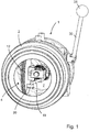
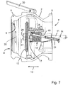
- An inventive connection fitting for a non-illustrated mineral oil tanker after Fig. 1 to 7 comprises as essential components a housing 1, a valve module 10 and an actuation module 29.
- the housing 1 provides a substantially cylindrical or coat-side closed housing wall 2 and a protruding from the housing 2 inwardly support 3 before.
- the housing 1 defines in the region of two opposite end faces a first flow opening 4 for a liquid and a second flow opening 7 for the liquid.
- the housing 1 is preferably made of a metallic material and provides one of the first flow opening 4 associated, the first flow opening 4 annularly surrounding first flange 5 and a second flow opening 7 associated with the second flange 8.
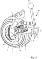
- On the second flange 8, a plurality of mutually spaced mounting holes 9 are provided, which serve to fix the connection fitting in particular to the mineral oil tanker vehicle.
- the valve module 10 is encompassed by the housing wall 2 of the housing 1 shell side in any case in sections.
- the valve module 10 provides a valve rod 11 held on the carrier 3 of the housing and a valve disk 12 held on the valve rod 11.
- the valve rod 11 is formed substantially cylindrical. It is held longitudinally displaceable in an axial direction 13.
- the valve rod 11 is in this case associated with a return spring 18, which surrounds the valve rod 11 and is provided between the carrier 3 and the valve plate 12.
- a hinge is provided with a first hinge element 15 fixed to the valve rod 11 and a second hinge element 16 fixed to the valve disk 12. In relation to a hinge axis defined by the hinge 17, this results in a pivotable arrangement of the valve disk 12 with respect to the valve rod 11.
- the axis of rotation 17 is oriented perpendicular to the axial direction 13 and spaced from a central axis 14 of the valve rod 11 extending in the axial direction 13. Due to the spacing of the rotation axis 17 from the central axis 14, an eccentric fixing of the valve disk 12 to the valve rod 11 is formed.
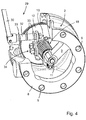
- valve module 10 provides an eccentric lever 19, which is rotatably and longitudinally displaceably held at a hinge point connected to the support 3 of the housing 1 bearing member 20 on the one hand and about a pivot axis 24 on the valve disc 12 on the other hand.
- the pivot axis 24 of the eccentric lever 19 is in this case oriented parallel to the axis of rotation 17 of the valve disk 12.
- the axis of rotation 17 and the pivot axis 24 are each oriented perpendicular to the axial direction 13 and to the central axis 14 of the valve rod eleventh
- the disk-shaped valve disk 12 which is flat in an extension plane 35, is placed against a valve seat 6 formed on the housing 1 in the region of the first flow opening 4.
- the installation of the valve disk 12 on the valve seat 6 is realized in such a way that the first flow opening 4 is closed.
- the valve rod 11 of the valve module 10 is in a first axial position and the plane of extent 35 of the valve disk 12 is oriented perpendicular to the axial direction 13.
- the pivot axis 24 and the rotation axis 17 are located on opposite sides of the central axis 14 of the valve rod 11. A minimum distance 27, 28 of the rotation axis 17 and the pivot axis 24 to the central axis 14 of the valve rod 11 is formed substantially equal.
- the valve module In order to fill a tank of the mineral oil tanker having the connection fitting according to the invention with the liquid, the valve module is brought into the filling position.
- the valve rod 11 is axially displaced with the valve disc 12 fixed thereto in a second axial position.
- an annular gap for the liquid In this respect, the liquid can flow into the connection fitting via the first flow opening 4 and passes via the annular gap to the second flow opening 7 and from there further in the direction of the tank of the mineral oil tank vehicle.
- the return spring 18 In the filling position, the return spring 18 is biased to pressure.
- valve rod 11 The axial displacement of the valve rod 11 with the valve plate 12 applied thereto is introduced when filling the tank via an external force, which acts on the valve plate 12.
- the valve disk 12 is mechanically contacted on a flat side opposite the valve rod 11 and axially displaced against the return spring 18.
- the return spring 18 is supported against the first hinge element 15 on the one hand and a bearing element 20 in the carrier 3 of the housing 1 on the other hand.
- the valve module In a removal position of the connection fitting according to the invention, the valve module is provided in the second axial position. However, the valve disk 12 is in this case arranged pivoted at least approximately 90 ° relative to the closed position or the filling position.
- the axial direction 13 of the valve rod 11 is oriented in the plane of extension 35 of the valve disk 12.
- To remove the liquid from the tank it first flows through the second flow opening 7 and the valve module 10 and exits via the first flow opening 4 from the connection fitting according to the invention. Due to the pivoted arrangement of the valve disk 12, no annular gap is formed between the valve disk 12 and the valve seat 6. In this respect, the liquid flows along the valve disk 12, which is rotated in a flow direction, in a substantially straight line through the connection fitting according to the invention.
- connection fitting To spend the connection fitting in the removal position, there is no need for any external force applied to the valve disk. Rather, the valve module is adjusted via the actuating module and initially consumed by a linear displacement of the valve rod in the second axial position. In order then to reach the removal position, there is no need for active actuation of the connection fitting according to the invention. Rather, the pivoting movement of the valve disk about the axis of rotation 17 is automatically effected solely on the basis of flowing through the connection fitting Liquid.
- valve rod 11 of the Ventilmoduls10 facing rear of the valve disk 12 is flown in the original orientation (filling) of the liquid and the liquid itself due to the eccentric position of the axis of rotation 17 on the valve disk 12th the pivoting movement about the axis of rotation 17 initiates.
- Mechanical actuating means or actuators for moving the valve module 10 into the removal position are therefore not required.
- valve rod 11 In order to spend the valve module 10 after the removal of the liquid from the tank of the mineral oil tank vehicle in the closed position, the valve rod 11 is longitudinally displaced from the second axial position in the direction of the first axial position. As a result of the displacement, approximately one third of the axial travel reaches an actuating spring 21 engaging the eccentric lever 19 in operative connection with the bearing element 20. As a result of the operative connection between the actuating spring 21 and the bearing element 20, a tensile load is imposed on the eccentric lever 19, which results in the valve disk 12 pivots back about the axis of rotation 17.
- the eccentric lever 19 is L-shaped so that the eccentric lever 19 engages with a free end of the valve disk 12 in a retaining element 25 eccentrically fixed to the valve disk 12.
- the eccentric lever 19 is rotatably fixed.
- a determination of the eccentric lever 19 on the holding element 25 via a split pin 26.
- a further spline 23 is provided on the eccentric lever 19 on a valve plate 12 facing away from the free end thereof.
- the actuating spring 21 is applied, which surrounds the eccentric lever 19 on a side facing away from the valve plate 12 of the bearing member 20.
- the actuating spring 21 is subjected to pressure between the bearing element 20 on the one hand and the washer 22 held by the split pin 23 on the other hand.
- the actuating spring 21 between the disc 22 and the bearing member 20 can be biased to pressure.
- a tensile load of the actuating spring 21 is not provided in contrast.
- a free displacement of the actuating spring 21 is provided on the eccentric lever 19 in the event that the valve rod 11 is provided in the second axial position. Due to the free arrangement of the actuating spring 21 in the second axial position the eccentric lever 19 in ebendon unloaded both in the filling position and in the removal position.
- the pivot position of the valve disk 12 is then defined solely by the flow direction of the liquid in the connection fitting according to the invention.
- connection fitting When the liquid flows through the connection fitting from the first flow opening towards the second flow opening, the axial direction is oriented perpendicular to the direction of extension of the valve disk 12 and the liquid is conveyed into the tank of the mineral oil tanker.
- the liquid When the liquid is withdrawn from the tank, the liquid flows through the connection fitting according to the invention from the second flow opening 7 in the direction of the first flow opening 4.
- forces of the valve disk 12 are applied to the rear side of the valve disk 12 as a result of the liquid flowing through.
- the provision of the valve disk when closing the removal fitting then takes place via the eccentric lever 19 and the special connection kinematics of the same.
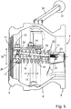
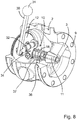
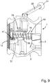
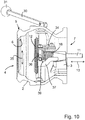
- a second embodiment of the connection fitting according to the invention according to the 8 to 11 basically has the same shape-defining components, namely the housing 1, the valve module 10 and the actuation module 29. Varying are the kinematics for moving the valve disk 12 and in particular the pivoting of the valve disk 12 about the axis of rotation 17. It is so far according to the second embodiment of the invention to the eccentric lever 19 and the add-on elements 20, 21, 22, 23 omitted. Rather, according to the second embodiment of the invention for influencing the pivotal movement of the valve disk 12 about the axis of rotation 17, a pin 36 is provided as a support member and a control link 37 as a guide element for the valve disk 12.
- the control link 37 is rotatably connected to the valve plate 12 and fixed to the valve plate 12 that together with the valve plate 12, the control link 37 is displaced both in the axial direction 13 and pivoted about the axis of rotation 17.
- the pin 36 is fixed in the housing 2 of the housing 1. On the housing wall 2 to a bore, not shown, in particular a blind hole is provided with a thread. Likewise, the pin 36 end has a thread, so that the pin 36 is screwed to the housing 2. Alternatively, any other way of fixing the pin 36 to the housing wall 2 may be provided.
- the pin 36 can be glued to the housing wall 2 and / or be connected to the housing wall 2 in a material-locking manner, for example via a weld and / or be cast on the housing 2.
- the pin shape is not mandatory for the support element.
- the pin 36 is assigned to the control link 37 so that the control link 37 in the closed position of the connection fitting after Fig. 9 is blocked with respect to a rotational movement about the rotation axis 17.
- the pin 36 passes into the effective range of a formed on the control cam 37 trough 39, so basically the pivotal movement of the valve disk 12 is released with the control cam 37 fixed thereto.
- valve disk 12 If the connection fitting is flowed through by the mineral oil from the first flow opening 4 in the direction of the second flow opening 7, the valve disk 12 is acted upon on the flat side opposite the control guide 37 and a pivoting movement of the valve disk 12 is not initiated due to the eccentric arrangement of the rotation axis 17.
- the valve disk 12 has a vertical orientation with respect to the axial direction 13 relative to its plane of extent 35.
- connection fitting flows through the second flow opening 7 in the direction of the first flow opening 4, due to the flow direction and the different size of the partial surfaces formed relative to the rotation axis 17 of the valve disk 12, a pivoting of the valve disk 12 about the rotation axis 17 results in that the plane of extent 35 is oriented substantially in the direction of the axial direction 13 and the connection fitting or the valve module 10 reaches the removal position.
- the pin 36 engages in this case in the formed on the control cam 37 trough 39 a.
- a pivoting movement of the valve disk 12 may be realized, for example, by a contact between the pin 36 and the control cam 37 in the region of the trough 39.
- connection fitting provides as described above, the set on the valve plate 12 control cam 37 and a pin 36, which with the control link 37 in the Closed position and / or in the filling position and / or in the removal position in an operative connection.
- the control link 37 is, as usual, displaceable together with the valve disk 12 in the axial direction 13 and pivotable about the axis of rotation 17.
- the pin 36 is not fixed directly to the housing 1. Rather, the pin 36 is fixed on the carrier 3 of the housing 1 via a pin carrier 38.
- the pin carrier 38 is designed, for example, in the manner of a sheet-metal forming part, and the pin 36 is detachably connected to the pin carrier 38 in a material-locking manner or via a screw connection (not shown).
- the trough 39 is formed on the control cam 37, so that in the removal position the pin 36 fixed to the pin carrier 38 is received in the region of the trough 39 and supported against the control cam 37.
- the geometry of the trough 39 is defined in the second and in the third embodiment of the connection fitting according to the invention so that when returning the valve module 10 from the removal position due to the longitudinal displacement in the axial direction 13, the control link 37 guided along the stationary pin 36 and the remindverschwenkung the valve disk 12 is introduced about the axis of rotation 17.
Landscapes
- Engineering & Computer Science (AREA)
- General Engineering & Computer Science (AREA)
- Mechanical Engineering (AREA)
- Health & Medical Sciences (AREA)
- Public Health (AREA)
- Transportation (AREA)
- Mechanically-Actuated Valves (AREA)
Applications Claiming Priority (1)
| Application Number | Priority Date | Filing Date | Title |
|---|---|---|---|
| DE202016101873.0U DE202016101873U1 (de) | 2016-04-08 | 2016-04-08 | Anschlussarmatur für ein Mineralölfahrzeug |
Publications (2)
| Publication Number | Publication Date |
|---|---|
| EP3232103A1 true EP3232103A1 (fr) | 2017-10-18 |
| EP3232103B1 EP3232103B1 (fr) | 2020-02-19 |
Family
ID=56552156
Family Applications (1)
| Application Number | Title | Priority Date | Filing Date |
|---|---|---|---|
| EP17163232.6A Active EP3232103B1 (fr) | 2016-04-08 | 2017-03-28 | Robinetterie de raccordement pour un véhicule de transports de produits pétroliers |
Country Status (3)
| Country | Link |
|---|---|
| EP (1) | EP3232103B1 (fr) |
| DE (1) | DE202016101873U1 (fr) |
| ES (1) | ES2778440T3 (fr) |
Families Citing this family (1)
| Publication number | Priority date | Publication date | Assignee | Title |
|---|---|---|---|---|
| FR3080149B1 (fr) * | 2018-04-13 | 2020-09-04 | Safran Aircraft Engines | Dispositif de prelevement d'air pour un moteur d'aeronef |
Citations (4)
| Publication number | Priority date | Publication date | Assignee | Title |
|---|---|---|---|---|
| FR1199122A (fr) * | 1958-12-15 | 1959-12-11 | Vanne étanche à opercule oscillant | |
| EP2058566A1 (fr) * | 2006-08-11 | 2009-05-13 | Nippon Valqua Industries, Ltd. | Vanne |
| EP2264342A2 (fr) * | 2009-06-11 | 2010-12-22 | Hsr Ag | Soupape à plateau |
| WO2012111910A1 (fr) * | 2011-02-18 | 2012-08-23 | (주)덕원기전 | Vanne papillon à triple excentration pour joint d'étanchéité double pression utilisant plusieurs feuilles |
Family Cites Families (1)
| Publication number | Priority date | Publication date | Assignee | Title |
|---|---|---|---|---|
| JP3201573U (ja) * | 2015-10-05 | 2015-12-17 | イハラサイエンス株式会社 | バルブ |
-
2016
- 2016-04-08 DE DE202016101873.0U patent/DE202016101873U1/de not_active Expired - Lifetime
-
2017
- 2017-03-28 ES ES17163232T patent/ES2778440T3/es active Active
- 2017-03-28 EP EP17163232.6A patent/EP3232103B1/fr active Active
Patent Citations (4)
| Publication number | Priority date | Publication date | Assignee | Title |
|---|---|---|---|---|
| FR1199122A (fr) * | 1958-12-15 | 1959-12-11 | Vanne étanche à opercule oscillant | |
| EP2058566A1 (fr) * | 2006-08-11 | 2009-05-13 | Nippon Valqua Industries, Ltd. | Vanne |
| EP2264342A2 (fr) * | 2009-06-11 | 2010-12-22 | Hsr Ag | Soupape à plateau |
| WO2012111910A1 (fr) * | 2011-02-18 | 2012-08-23 | (주)덕원기전 | Vanne papillon à triple excentration pour joint d'étanchéité double pression utilisant plusieurs feuilles |
Also Published As
| Publication number | Publication date |
|---|---|
| DE202016101873U1 (de) | 2016-07-12 |
| EP3232103B1 (fr) | 2020-02-19 |
| ES2778440T3 (es) | 2020-08-10 |
Similar Documents
| Publication | Publication Date | Title |
|---|---|---|
| DE112015001153B4 (de) | Schnellkopplungsvorrichtung | |
| DE1803417C3 (de) | Zug- und Stoßvorrichtung für Eisenbahnwagen | |
| DE2810446C2 (de) | Kugelhahn | |
| EP2640600B1 (fr) | Dispositif de réglage d'un siège de véhicule présentant un frein à auto-ajustement | |
| DE2505358A1 (de) | Arbeits- und verstrebungszylinder | |
| DE3411054C2 (fr) | ||
| DE102014111344A1 (de) | Spannvorrichtung | |
| DE102006061017B4 (de) | Stellgerät und Verfahren zum Einstellen eines maximalen Verlagerungswegs einer Antriebsstange eines Stellantriebs des Stellgeräts | |
| DE2402542A1 (de) | Bremsvorrichtung fuer fahrzeuge, insbesondere lastkraftwagen und busse | |
| DE1912086B2 (de) | GestängenachsteUeinrichtung für das Bremsgestänge eines Eisenbahnwagens | |
| EP3807012B1 (fr) | Centrifugeuse | |
| EP3232103A1 (fr) | Robinetterie de raccordement pour un véhicule de transports de produits pétroliers | |
| EP1905545B1 (fr) | Tendeur à ressort pour ressort cylindrique | |
| DE102019121860A1 (de) | Spannvorrichtung | |
| DE10147981A1 (de) | Verbindungselement zur Verbindung eines Kolbens mit einem Rückstellelement | |
| EP1613865B1 (fr) | Dispositif de rotation ou de pivotement et module de raccordement pour dispositif de rotation ou de pivotement | |
| EP3623267B9 (fr) | Dispositif de réglage d'un premier composant et d'un deuxième composant d'un moyen de transport des personnes et / ou des marchandises relatives les unes aux autres ainsi que moyen de transport des personnes et / ou des marchandises doté d'un tel dispositif | |
| EP3429901B1 (fr) | Système d'accouplement à désaxement pneumatique | |
| DE3232322A1 (de) | Hydraulische kettenspannvorrichtung | |
| DE10058275A1 (de) | Kraftfahrzeugservolenkung | |
| DE2730135A1 (de) | Kraftverstaerktes zahnstangen-lenkgetriebe | |
| DE3233412C2 (de) | Federkraftantrieb für einen elektrischen Hochspannungsschalter | |
| DE102014004844A1 (de) | Kulissenscheibe für einen modular aufgebauten Sicherheitsfahrschalter | |
| DE2400470C3 (de) | Selbsttätige Nachstellvorrichtung für eine Teilbelagscheibenbremse | |
| EP0444500A1 (fr) | Outil de fermeture pour capuchons de scellage de fûts |
Legal Events
| Date | Code | Title | Description |
|---|---|---|---|
| PUAI | Public reference made under article 153(3) epc to a published international application that has entered the european phase |
Free format text: ORIGINAL CODE: 0009012 |
|
| STAA | Information on the status of an ep patent application or granted ep patent |
Free format text: STATUS: THE APPLICATION HAS BEEN PUBLISHED |
|
| AK | Designated contracting states |
Kind code of ref document: A1 Designated state(s): AL AT BE BG CH CY CZ DE DK EE ES FI FR GB GR HR HU IE IS IT LI LT LU LV MC MK MT NL NO PL PT RO RS SE SI SK SM TR |
|
| AX | Request for extension of the european patent |
Extension state: BA ME |
|
| STAA | Information on the status of an ep patent application or granted ep patent |
Free format text: STATUS: REQUEST FOR EXAMINATION WAS MADE |
|
| 17P | Request for examination filed |
Effective date: 20171129 |
|
| RBV | Designated contracting states (corrected) |
Designated state(s): AL AT BE BG CH CY CZ DE DK EE ES FI FR GB GR HR HU IE IS IT LI LT LU LV MC MK MT NL NO PL PT RO RS SE SI SK SM TR |
|
| GRAP | Despatch of communication of intention to grant a patent |
Free format text: ORIGINAL CODE: EPIDOSNIGR1 |
|
| STAA | Information on the status of an ep patent application or granted ep patent |
Free format text: STATUS: GRANT OF PATENT IS INTENDED |
|
| INTG | Intention to grant announced |
Effective date: 20191025 |
|
| GRAS | Grant fee paid |
Free format text: ORIGINAL CODE: EPIDOSNIGR3 |
|
| GRAA | (expected) grant |
Free format text: ORIGINAL CODE: 0009210 |
|
| STAA | Information on the status of an ep patent application or granted ep patent |
Free format text: STATUS: THE PATENT HAS BEEN GRANTED |
|
| AK | Designated contracting states |
Kind code of ref document: B1 Designated state(s): AL AT BE BG CH CY CZ DE DK EE ES FI FR GB GR HR HU IE IS IT LI LT LU LV MC MK MT NL NO PL PT RO RS SE SI SK SM TR |
|
| REG | Reference to a national code |
Ref country code: CH Ref legal event code: EP |
|
| REG | Reference to a national code |
Ref country code: DE Ref legal event code: R096 Ref document number: 502017003825 Country of ref document: DE |
|
| REG | Reference to a national code |
Ref country code: AT Ref legal event code: REF Ref document number: 1235359 Country of ref document: AT Kind code of ref document: T Effective date: 20200315 |
|
| REG | Reference to a national code |
Ref country code: IE Ref legal event code: FG4D Free format text: LANGUAGE OF EP DOCUMENT: GERMAN |
|
| REG | Reference to a national code |
Ref country code: SE Ref legal event code: TRGR |
|
| REG | Reference to a national code |
Ref country code: GR Ref legal event code: EP Ref document number: 20200401291 Country of ref document: GR Effective date: 20200716 |
|
| REG | Reference to a national code |
Ref country code: NL Ref legal event code: MP Effective date: 20200219 |
|
| PG25 | Lapsed in a contracting state [announced via postgrant information from national office to epo] |
Ref country code: NO Free format text: LAPSE BECAUSE OF FAILURE TO SUBMIT A TRANSLATION OF THE DESCRIPTION OR TO PAY THE FEE WITHIN THE PRESCRIBED TIME-LIMIT Effective date: 20200519 Ref country code: FI Free format text: LAPSE BECAUSE OF FAILURE TO SUBMIT A TRANSLATION OF THE DESCRIPTION OR TO PAY THE FEE WITHIN THE PRESCRIBED TIME-LIMIT Effective date: 20200219 Ref country code: RS Free format text: LAPSE BECAUSE OF FAILURE TO SUBMIT A TRANSLATION OF THE DESCRIPTION OR TO PAY THE FEE WITHIN THE PRESCRIBED TIME-LIMIT Effective date: 20200219 |
|
| REG | Reference to a national code |
Ref country code: ES Ref legal event code: FG2A Ref document number: 2778440 Country of ref document: ES Kind code of ref document: T3 Effective date: 20200810 |
|
| REG | Reference to a national code |
Ref country code: LT Ref legal event code: MG4D |
|
| PG25 | Lapsed in a contracting state [announced via postgrant information from national office to epo] |
Ref country code: IS Free format text: LAPSE BECAUSE OF FAILURE TO SUBMIT A TRANSLATION OF THE DESCRIPTION OR TO PAY THE FEE WITHIN THE PRESCRIBED TIME-LIMIT Effective date: 20200619 Ref country code: LV Free format text: LAPSE BECAUSE OF FAILURE TO SUBMIT A TRANSLATION OF THE DESCRIPTION OR TO PAY THE FEE WITHIN THE PRESCRIBED TIME-LIMIT Effective date: 20200219 Ref country code: HR Free format text: LAPSE BECAUSE OF FAILURE TO SUBMIT A TRANSLATION OF THE DESCRIPTION OR TO PAY THE FEE WITHIN THE PRESCRIBED TIME-LIMIT Effective date: 20200219 Ref country code: BG Free format text: LAPSE BECAUSE OF FAILURE TO SUBMIT A TRANSLATION OF THE DESCRIPTION OR TO PAY THE FEE WITHIN THE PRESCRIBED TIME-LIMIT Effective date: 20200519 |
|
| PG25 | Lapsed in a contracting state [announced via postgrant information from national office to epo] |
Ref country code: NL Free format text: LAPSE BECAUSE OF FAILURE TO SUBMIT A TRANSLATION OF THE DESCRIPTION OR TO PAY THE FEE WITHIN THE PRESCRIBED TIME-LIMIT Effective date: 20200219 |
|
| PG25 | Lapsed in a contracting state [announced via postgrant information from national office to epo] |
Ref country code: SM Free format text: LAPSE BECAUSE OF FAILURE TO SUBMIT A TRANSLATION OF THE DESCRIPTION OR TO PAY THE FEE WITHIN THE PRESCRIBED TIME-LIMIT Effective date: 20200219 Ref country code: EE Free format text: LAPSE BECAUSE OF FAILURE TO SUBMIT A TRANSLATION OF THE DESCRIPTION OR TO PAY THE FEE WITHIN THE PRESCRIBED TIME-LIMIT Effective date: 20200219 Ref country code: SK Free format text: LAPSE BECAUSE OF FAILURE TO SUBMIT A TRANSLATION OF THE DESCRIPTION OR TO PAY THE FEE WITHIN THE PRESCRIBED TIME-LIMIT Effective date: 20200219 Ref country code: RO Free format text: LAPSE BECAUSE OF FAILURE TO SUBMIT A TRANSLATION OF THE DESCRIPTION OR TO PAY THE FEE WITHIN THE PRESCRIBED TIME-LIMIT Effective date: 20200219 Ref country code: LT Free format text: LAPSE BECAUSE OF FAILURE TO SUBMIT A TRANSLATION OF THE DESCRIPTION OR TO PAY THE FEE WITHIN THE PRESCRIBED TIME-LIMIT Effective date: 20200219 Ref country code: DK Free format text: LAPSE BECAUSE OF FAILURE TO SUBMIT A TRANSLATION OF THE DESCRIPTION OR TO PAY THE FEE WITHIN THE PRESCRIBED TIME-LIMIT Effective date: 20200219 Ref country code: PT Free format text: LAPSE BECAUSE OF FAILURE TO SUBMIT A TRANSLATION OF THE DESCRIPTION OR TO PAY THE FEE WITHIN THE PRESCRIBED TIME-LIMIT Effective date: 20200712 |
|
| REG | Reference to a national code |
Ref country code: CH Ref legal event code: PL |
|
| REG | Reference to a national code |
Ref country code: DE Ref legal event code: R097 Ref document number: 502017003825 Country of ref document: DE |
|
| PG25 | Lapsed in a contracting state [announced via postgrant information from national office to epo] |
Ref country code: MC Free format text: LAPSE BECAUSE OF FAILURE TO SUBMIT A TRANSLATION OF THE DESCRIPTION OR TO PAY THE FEE WITHIN THE PRESCRIBED TIME-LIMIT Effective date: 20200219 |
|
| REG | Reference to a national code |
Ref country code: BE Ref legal event code: MM Effective date: 20200331 |
|
| PLBE | No opposition filed within time limit |
Free format text: ORIGINAL CODE: 0009261 |
|
| STAA | Information on the status of an ep patent application or granted ep patent |
Free format text: STATUS: NO OPPOSITION FILED WITHIN TIME LIMIT |
|
| PG25 | Lapsed in a contracting state [announced via postgrant information from national office to epo] |
Ref country code: LU Free format text: LAPSE BECAUSE OF NON-PAYMENT OF DUE FEES Effective date: 20200328 |
|
| 26N | No opposition filed |
Effective date: 20201120 |
|
| PG25 | Lapsed in a contracting state [announced via postgrant information from national office to epo] |
Ref country code: CH Free format text: LAPSE BECAUSE OF NON-PAYMENT OF DUE FEES Effective date: 20200331 Ref country code: IE Free format text: LAPSE BECAUSE OF NON-PAYMENT OF DUE FEES Effective date: 20200328 Ref country code: LI Free format text: LAPSE BECAUSE OF NON-PAYMENT OF DUE FEES Effective date: 20200331 |
|
| PG25 | Lapsed in a contracting state [announced via postgrant information from national office to epo] |
Ref country code: SI Free format text: LAPSE BECAUSE OF FAILURE TO SUBMIT A TRANSLATION OF THE DESCRIPTION OR TO PAY THE FEE WITHIN THE PRESCRIBED TIME-LIMIT Effective date: 20200219 Ref country code: BE Free format text: LAPSE BECAUSE OF NON-PAYMENT OF DUE FEES Effective date: 20200331 Ref country code: PL Free format text: LAPSE BECAUSE OF FAILURE TO SUBMIT A TRANSLATION OF THE DESCRIPTION OR TO PAY THE FEE WITHIN THE PRESCRIBED TIME-LIMIT Effective date: 20200219 |
|
| PG25 | Lapsed in a contracting state [announced via postgrant information from national office to epo] |
Ref country code: MT Free format text: LAPSE BECAUSE OF FAILURE TO SUBMIT A TRANSLATION OF THE DESCRIPTION OR TO PAY THE FEE WITHIN THE PRESCRIBED TIME-LIMIT Effective date: 20200219 Ref country code: CY Free format text: LAPSE BECAUSE OF FAILURE TO SUBMIT A TRANSLATION OF THE DESCRIPTION OR TO PAY THE FEE WITHIN THE PRESCRIBED TIME-LIMIT Effective date: 20200219 |
|
| PGFP | Annual fee paid to national office [announced via postgrant information from national office to epo] |
Ref country code: SE Payment date: 20220324 Year of fee payment: 6 Ref country code: CZ Payment date: 20220324 Year of fee payment: 6 |
|
| PG25 | Lapsed in a contracting state [announced via postgrant information from national office to epo] |
Ref country code: MK Free format text: LAPSE BECAUSE OF FAILURE TO SUBMIT A TRANSLATION OF THE DESCRIPTION OR TO PAY THE FEE WITHIN THE PRESCRIBED TIME-LIMIT Effective date: 20200219 Ref country code: AL Free format text: LAPSE BECAUSE OF FAILURE TO SUBMIT A TRANSLATION OF THE DESCRIPTION OR TO PAY THE FEE WITHIN THE PRESCRIBED TIME-LIMIT Effective date: 20200219 |
|
| REG | Reference to a national code |
Ref country code: AT Ref legal event code: MM01 Ref document number: 1235359 Country of ref document: AT Kind code of ref document: T Effective date: 20220328 |
|
| PG25 | Lapsed in a contracting state [announced via postgrant information from national office to epo] |
Ref country code: AT Free format text: LAPSE BECAUSE OF NON-PAYMENT OF DUE FEES Effective date: 20220328 |
|
| PG25 | Lapsed in a contracting state [announced via postgrant information from national office to epo] |
Ref country code: CZ Free format text: LAPSE BECAUSE OF NON-PAYMENT OF DUE FEES Effective date: 20230328 |
|
| REG | Reference to a national code |
Ref country code: SE Ref legal event code: EUG |
|
| PG25 | Lapsed in a contracting state [announced via postgrant information from national office to epo] |
Ref country code: SE Free format text: LAPSE BECAUSE OF NON-PAYMENT OF DUE FEES Effective date: 20230329 |
|
| REG | Reference to a national code |
Ref country code: DE Ref legal event code: R082 Ref document number: 502017003825 Country of ref document: DE Representative=s name: WICKORD BUSER PATENTANWAELTE PARTG MBB, DE |
|
| PGFP | Annual fee paid to national office [announced via postgrant information from national office to epo] |
Ref country code: GR Payment date: 20240319 Year of fee payment: 8 |
|
| PGFP | Annual fee paid to national office [announced via postgrant information from national office to epo] |
Ref country code: DE Payment date: 20240327 Year of fee payment: 8 Ref country code: GB Payment date: 20240322 Year of fee payment: 8 |
|
| PGFP | Annual fee paid to national office [announced via postgrant information from national office to epo] |
Ref country code: TR Payment date: 20240318 Year of fee payment: 8 Ref country code: IT Payment date: 20240329 Year of fee payment: 8 Ref country code: FR Payment date: 20240320 Year of fee payment: 8 |
|
| PGFP | Annual fee paid to national office [announced via postgrant information from national office to epo] |
Ref country code: ES Payment date: 20240417 Year of fee payment: 8 |
|
| REG | Reference to a national code |
Ref country code: DE Ref legal event code: R119 Ref document number: 502017003825 Country of ref document: DE |
|
| GBPC | Gb: european patent ceased through non-payment of renewal fee |
Effective date: 20250328 |
|
| PG25 | Lapsed in a contracting state [announced via postgrant information from national office to epo] |
Ref country code: DE Free format text: LAPSE BECAUSE OF NON-PAYMENT OF DUE FEES Effective date: 20251001 |
|
| PG25 | Lapsed in a contracting state [announced via postgrant information from national office to epo] |
Ref country code: GB Free format text: LAPSE BECAUSE OF NON-PAYMENT OF DUE FEES Effective date: 20250328 |
|
| PG25 | Lapsed in a contracting state [announced via postgrant information from national office to epo] |
Ref country code: FR Free format text: LAPSE BECAUSE OF NON-PAYMENT OF DUE FEES Effective date: 20250331 Ref country code: IT Free format text: LAPSE BECAUSE OF NON-PAYMENT OF DUE FEES Effective date: 20250328 |
|
| PG25 | Lapsed in a contracting state [announced via postgrant information from national office to epo] |
Ref country code: GR Free format text: LAPSE BECAUSE OF NON-PAYMENT OF DUE FEES Effective date: 20251003 |