EP3230731B1 - Analyseanordnung zur wasser- und abwasseranalyse - Google Patents
Analyseanordnung zur wasser- und abwasseranalyse Download PDFInfo
- Publication number
- EP3230731B1 EP3230731B1 EP15834790.6A EP15834790A EP3230731B1 EP 3230731 B1 EP3230731 B1 EP 3230731B1 EP 15834790 A EP15834790 A EP 15834790A EP 3230731 B1 EP3230731 B1 EP 3230731B1
- Authority
- EP
- European Patent Office
- Prior art keywords
- injection
- needle
- syringe
- reaction vessel
- injection needle
- Prior art date
- Legal status (The legal status is an assumption and is not a legal conclusion. Google has not performed a legal analysis and makes no representation as to the accuracy of the status listed.)
- Active
Links
- XLYOFNOQVPJJNP-UHFFFAOYSA-N water Substances O XLYOFNOQVPJJNP-UHFFFAOYSA-N 0.000 title claims description 5
- 239000002351 wastewater Substances 0.000 title claims description 4
- 238000002347 injection Methods 0.000 claims description 45
- 239000007924 injection Substances 0.000 claims description 45
- 239000000126 substance Substances 0.000 claims description 7
- 230000035515 penetration Effects 0.000 claims description 3
- 230000029087 digestion Effects 0.000 claims description 2
- IJGRMHOSHXDMSA-UHFFFAOYSA-N Atomic nitrogen Chemical compound N#N IJGRMHOSHXDMSA-UHFFFAOYSA-N 0.000 description 10
- 230000010354 integration Effects 0.000 description 7
- 230000006835 compression Effects 0.000 description 6
- 238000007906 compression Methods 0.000 description 6
- QVGXLLKOCUKJST-UHFFFAOYSA-N atomic oxygen Chemical compound [O] QVGXLLKOCUKJST-UHFFFAOYSA-N 0.000 description 5
- 229910052757 nitrogen Inorganic materials 0.000 description 5
- 239000001301 oxygen Substances 0.000 description 5
- 229910052760 oxygen Inorganic materials 0.000 description 5
- 238000005259 measurement Methods 0.000 description 3
- 239000012494 Quartz wool Substances 0.000 description 2
- 239000002253 acid Substances 0.000 description 2
- 239000012159 carrier gas Substances 0.000 description 2
- 238000013461 design Methods 0.000 description 2
- 230000000694 effects Effects 0.000 description 2
- 238000012805 post-processing Methods 0.000 description 2
- 230000036962 time dependent Effects 0.000 description 2
- 229910000831 Steel Inorganic materials 0.000 description 1
- 238000001514 detection method Methods 0.000 description 1
- 238000011156 evaluation Methods 0.000 description 1
- 239000007789 gas Substances 0.000 description 1
- 238000000034 method Methods 0.000 description 1
- 238000012986 modification Methods 0.000 description 1
- 230000004048 modification Effects 0.000 description 1
- 238000012545 processing Methods 0.000 description 1
- 239000010959 steel Substances 0.000 description 1
Images


Classifications
-
- G—PHYSICS
- G01—MEASURING; TESTING
- G01N—INVESTIGATING OR ANALYSING MATERIALS BY DETERMINING THEIR CHEMICAL OR PHYSICAL PROPERTIES
- G01N33/00—Investigating or analysing materials by specific methods not covered by groups G01N1/00 - G01N31/00
- G01N33/18—Water
- G01N33/1806—Water biological or chemical oxygen demand (BOD or COD)
-
- B—PERFORMING OPERATIONS; TRANSPORTING
- B01—PHYSICAL OR CHEMICAL PROCESSES OR APPARATUS IN GENERAL
- B01L—CHEMICAL OR PHYSICAL LABORATORY APPARATUS FOR GENERAL USE
- B01L3/00—Containers or dishes for laboratory use, e.g. laboratory glassware; Droppers
- B01L3/50—Containers for the purpose of retaining a material to be analysed, e.g. test tubes
-
- G—PHYSICS
- G01—MEASURING; TESTING
- G01N—INVESTIGATING OR ANALYSING MATERIALS BY DETERMINING THEIR CHEMICAL OR PHYSICAL PROPERTIES
- G01N1/00—Sampling; Preparing specimens for investigation
- G01N1/02—Devices for withdrawing samples
- G01N1/10—Devices for withdrawing samples in the liquid or fluent state
- G01N1/14—Suction devices, e.g. pumps; Ejector devices
-
- G—PHYSICS
- G01—MEASURING; TESTING
- G01N—INVESTIGATING OR ANALYSING MATERIALS BY DETERMINING THEIR CHEMICAL OR PHYSICAL PROPERTIES
- G01N31/00—Investigating or analysing non-biological materials by the use of the chemical methods specified in the subgroup; Apparatus specially adapted for such methods
- G01N31/12—Investigating or analysing non-biological materials by the use of the chemical methods specified in the subgroup; Apparatus specially adapted for such methods using combustion
-
- G—PHYSICS
- G01—MEASURING; TESTING
- G01N—INVESTIGATING OR ANALYSING MATERIALS BY DETERMINING THEIR CHEMICAL OR PHYSICAL PROPERTIES
- G01N33/00—Investigating or analysing materials by specific methods not covered by groups G01N1/00 - G01N31/00
- G01N33/18—Water
- G01N33/1826—Water organic contamination in water
- G01N33/1846—Total carbon analysis
-
- B—PERFORMING OPERATIONS; TRANSPORTING
- B01—PHYSICAL OR CHEMICAL PROCESSES OR APPARATUS IN GENERAL
- B01L—CHEMICAL OR PHYSICAL LABORATORY APPARATUS FOR GENERAL USE
- B01L2200/00—Solutions for specific problems relating to chemical or physical laboratory apparatus
- B01L2200/02—Adapting objects or devices to another
- B01L2200/025—Align devices or objects to ensure defined positions relative to each other
-
- B—PERFORMING OPERATIONS; TRANSPORTING
- B01—PHYSICAL OR CHEMICAL PROCESSES OR APPARATUS IN GENERAL
- B01L—CHEMICAL OR PHYSICAL LABORATORY APPARATUS FOR GENERAL USE
- B01L2200/00—Solutions for specific problems relating to chemical or physical laboratory apparatus
- B01L2200/06—Fluid handling related problems
- B01L2200/0642—Filling fluids into wells by specific techniques
-
- B—PERFORMING OPERATIONS; TRANSPORTING
- B01—PHYSICAL OR CHEMICAL PROCESSES OR APPARATUS IN GENERAL
- B01L—CHEMICAL OR PHYSICAL LABORATORY APPARATUS FOR GENERAL USE
- B01L2200/00—Solutions for specific problems relating to chemical or physical laboratory apparatus
- B01L2200/16—Reagents, handling or storing thereof
-
- B—PERFORMING OPERATIONS; TRANSPORTING
- B01—PHYSICAL OR CHEMICAL PROCESSES OR APPARATUS IN GENERAL
- B01L—CHEMICAL OR PHYSICAL LABORATORY APPARATUS FOR GENERAL USE
- B01L2300/00—Additional constructional details
- B01L2300/06—Auxiliary integrated devices, integrated components
- B01L2300/0672—Integrated piercing tool
-
- B—PERFORMING OPERATIONS; TRANSPORTING
- B01—PHYSICAL OR CHEMICAL PROCESSES OR APPARATUS IN GENERAL
- B01L—CHEMICAL OR PHYSICAL LABORATORY APPARATUS FOR GENERAL USE
- B01L2300/00—Additional constructional details
- B01L2300/08—Geometry, shape and general structure
- B01L2300/0832—Geometry, shape and general structure cylindrical, tube shaped
-
- B—PERFORMING OPERATIONS; TRANSPORTING
- B01—PHYSICAL OR CHEMICAL PROCESSES OR APPARATUS IN GENERAL
- B01L—CHEMICAL OR PHYSICAL LABORATORY APPARATUS FOR GENERAL USE
- B01L2300/00—Additional constructional details
- B01L2300/14—Means for pressure control
-
- B—PERFORMING OPERATIONS; TRANSPORTING
- B01—PHYSICAL OR CHEMICAL PROCESSES OR APPARATUS IN GENERAL
- B01L—CHEMICAL OR PHYSICAL LABORATORY APPARATUS FOR GENERAL USE
- B01L2400/00—Moving or stopping fluids
- B01L2400/04—Moving fluids with specific forces or mechanical means
- B01L2400/0475—Moving fluids with specific forces or mechanical means specific mechanical means and fluid pressure
- B01L2400/0478—Moving fluids with specific forces or mechanical means specific mechanical means and fluid pressure pistons
Definitions
- the invention relates to an analysis arrangement for water and wastewater analysis, comprising an analyzer with a device housing and an injection port for introducing a sample into the device and an injection syringe.
- the invention is based on the object to provide an improved analysis arrangement of this kind, which can deliver in particular reliably accurate and exactly reproducible analysis results.
- the invention initially includes the idea of the associated syringe, deviating from conventional hypodermic syringes, in the interest of an optimal and reproducible implementation of the injection process modify.
- an outlet opening of the needle is provided, the surface normal coincides with the needle longitudinal axis.
- an automatically acting ejection element is provided for ejecting a predetermined amount of substance in a predetermined injection period.
- the injection port is connected to a cylindrical reaction vessel for thermal digestion of the substance to be analyzed, and it has guide means for guiding the injection syringe to a predetermined injection position.
- the guide means are designed in accordance with the shape of the injection needle such that the longitudinal axis of the inserted injection needle coincides with the longitudinal axis of the reaction vessel.
- the guide means comprise a cylindrical or conical guide sleeve.
- the guide means have a stop for limiting the depth of penetration of the injection needle into the reaction vessel.
- the ejection element is designed as a lockable compression spring which acts on the piston of the injection syringe.
- the compression spring which may be formed for example as a steel cylinder spring, thus replacing a manual actuation of the syringe.
- the predetermined spring characteristic of the compression spring ensures a precisely reproducible sample output per unit time.
- the realization of this important effect does not necessarily take place by a compression spring (as a particularly simple and cost-effective design), but can also be done, for example, by a small linear motor or a hydraulic or pneumatic drive with a predetermined discharge characteristic.
- COD or COD chemical oxygen demand
- the analyzer 1 comprises a thermal reaction vessel or an oven EB into which a water sample can be injected by means of a syringe MM via an injection port P arranged at the top of the oven and in which this sample is thermally digested.
- the furnace is fed via a check valve RM1, a carrier gas stream, which is composed of air and nitrogen.
- the carrier gas flow is controlled by means of an air pressure regulator KH1, a nitrogen pressure regulator KH2, an air flow regulator KH4 and a nitrogen flow controller KH5 controlled and filtered by means of a first and second fine filter HQ1, HQ2 input side of the furnace.
- the gas stream On the output side of the furnace, the gas stream first passes into a condensate vessel CM1, and the non-condensed fraction then passes through a quartz wool filter HQ3 and an acid trap HS1 before it reaches the oxygen detector B1, which finally outputs an (electrical) measured value to an adjustable evaluation device A, in which in particular an integration time is provided for the integration of a time-dependent detected oxygen detection signal; see below.
- Fig. 2 shows the analyzer 1 in a perspective view in a state in which the device housing 1 'is partially open and a part of the device components is pulled out of the housing.
- the device housing has essentially the shape of a square prism, and in the front of the device 1A 'is an opening 1B' is provided, which is closed by a hinged on the left side edge of the device front, perforated door 3.
- the device housing 1 'with the door 3 is closed.
- control panel 1C' On the right side of the front panel 1A 'is a control panel 1C', on which a plurality of control and display elements are arranged, including a temperature display / control TC and the air pressure or nitrogen pressure adjustment regulators KH1 and KH2 and the associated display elements BP1 and BP1.
- the injection port P On the upper side of the device 1D 'there is the injection port P, whose structure and dimensions correspond to those of the Fig. 1 syringe MM are adapted and communicates inside the device with a corresponding injection valve EB1 of the furnace EB when the furnace is in its normal position of use within the device housing.
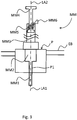
- Fig. 3 shows in a sketch in a longitudinal sectional view of the basic structure and the coordinated geometric configuration of the injection syringe MM and the injection port P of the furnace EB of the analysis arrangement.
- the injection port P comprises a guide sleeve P1 which is substantially cylindrical in its longitudinal course and whose diameter and length are matched to the corresponding dimensions of an injection needle MM1 of the injection syringe MM and whose longitudinal axis coincides with a longitudinal axis LA1 of the furnace EB which is cylindrical in its basic form.
- an enlarged diameter bore P2 Provided on the upper side of the injection port P is an enlarged diameter bore P2, the dimensions of which are adapted to those of a needle hub MM2 of the syringe and whose lower end face acts as a depth limiting stop when the injection syringe is inserted. With this stop, a precisely predetermined position of the needle end cut off at right angles to the needle longitudinal axis LA2 of the injection syringe in the oven EB and thus a precisely predetermined injection point is ensured.
- a syringe piston MM4 is mounted longitudinally displaceable, the free end is designed in the usual way for manually mounting a sample.
- a compression spring MM5 is embedded, the upper end is supported against the upper end wall of the syringe reservoir and the lower end acts on the end of the syringe piston MM4.
- the syringe piston MM5 is locked by means of a locking lever MM5.
- the syringe plunger MM4 is pressed down by the force of the compression spring MM5 and the sample contained in the syringe reservoir MM3 is injected into the furnace at a predetermined time interval or at a predetermined discharge speed.
- This discharge of the predetermined amount of sample at exactly predetermined speed or in a precisely defined time interval is as important for reproducible analysis results as the exact injection position and direction, which are ensured by the special design of the injection needle and the injection port.
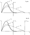
- Fig. 4a and 4b illustrate the effect of an adjustable integration time of the post-processing device A for processing a time-dependent recorded oxygen measurement signal.
- Fig. 4a shows here three different waveforms with (according to the prior art) fixed set integration time t i . It can be seen that only the integration of the measurement signal S 1 represented by the solid line leads to a correct result, while the set integration time for the measurement signals S 2 and S 3 is obviously too short and essential signal components are not detected. Remedy here in the Fig. 4b shown setting of a longer integration time t i2, 3 for the signals S 2 and S 3 , which can make the operator of the analysis arrangement in response to the detected waveform at the post-processing device A.
Description
- Die Erfindung betrifft eine Analyseanordnung zur Wasser- und Abwasseranalyse, die ein Analysegerät mit einem Gerätegehäuse und einem Injektionsport zur Einführung einer Probe in das Gerät sowie eine Injektionsspritze umfasst.
- Derartige Analyseanordnungen sind an sich bekannt, z.B. aus der
EP1022564A2 , und werden auch von der Anmelderin hergestellt und angeboten. - Der Erfindung liegt die Aufgabe zu Grunde, eine verbesserte Analyseanordnung dieser Art bereitzustellen, die insbesondere verlässlich genaue und exakt reproduzierbare Analyseergebnisse liefern kann.
- Diese Aufgabe wird nach einem ersten Aspekt der Erfindung gelöst durch eine Analyseanordnung mit den Merkmalen des Anspruchs 1.
- Die Erfindung schließt zunächst den Gedanken ein, die zugehörige Injektionsspritze, abweichend von herkömmlichen Injektionsspritzen, im Interesse einer optimalen und reproduzierbaren Durchführung des Injektionsvorganges zu modifizieren. Dabei ist eine Austrittsöffnung der Nadel vorgesehen, deren Flächennormale mit der Nadel-Längsachse zusammenfällt. Weiter ist ein selbsttätig wirkendes Ausstoßelement zum Ausstoßen einer vorbestimmten Stoffmenge in einer vorbestimmten Injektionszeitspanne vorgesehen.
- In der Erfindung ist der Injektionsport mit einem zylindrischen Reaktionsgefäß zum thermischen Aufschluss des zu analysierenden Stoffes verbunden, und er weist Führungsmittel zum Führen der Injektionsspritze in eine vorbestimmte Einspritzposition auf. Speziell sind die Führungsmittel in Abstimmung auf die Form der Injektionsnadel derart ausgebildet, dass die Längsachse der eingeführten Injektionsnadel mit der Längsachse des Reaktionsgefäßes zusammenfällt. Die Führungsmittel umfassen eine zylindrische oder konische Führungshülse. Weiter weisen die Führungsmittel einen Anschlag zur Begrenzung der Tiefe des Eindringens der Injektionsnadel in das Reaktionsgefäß auf.
- In einer weiteren Ausführung der Erfindung ist das Ausstoßelement als verriegelbare Druckfeder ausgebildet, die auf den Kolben der Injektionsspritze wirkt. Die Druckfeder, die beispielsweise als stählerne Zylinderfeder ausgebildet sein kann, ersetzt also eine manuelle Betätigung der Spritze. Anders als bei der manuellen Betätigung, sichert die vorbestimmte Federcharakteristik der Druckfeder einen exakt reproduzierbaren Probenausstoß pro Zeiteinheit. Die Realisierung dieser wichtigen Wirkung muss aber nicht notwendigerweise durch eine Druckfeder (als besonders einfache und kostengünstige Ausführung) erfolgen, sondern kann beispielsweise auch durch einen kleinen Linearmotor oder einen hydraulischen oder pneumatischen Antrieb mit vorbestimmter Ausstoßcharakteristik erfolgen.
- Vorteile und Zweckmäßigkeiten der Erfindung ergeben sich im Übrigen aus der nachfolgenden kurzen Beschreibung eines Ausführungsbeispiels anhand der Figuren. Von diesen zeigen:
-
Fig. 1 eine schematische Darstellung wesentlicher Gerätekomponenten eines Analysegerätes gemäß einem Ausführungsbeispiel, -
Fig. 2 eine perspektivische Darstellung jenes Analysegerätes, -
Fig. 3 eine schematische Längsschnittdarstellung einer Injektionsspritze mit in den Injektionsport eingeführter Injektionsnadel gemäß einer beispielhaften Ausführungsform der Analyseanordnung und -
Fig. 4a und 4b grafische Darstellungen zur Illustration eines Aspekts der Erfindung. -
Fig. 1 und2 zeigen schematisch wesentliche Teile eines Analysegerätes 1 zur Bestimmung des chemischen Sauerstoffbedarfs (CSB oder COD = chemical oxygen demand) von Wasser oder Abwasser. Der grundsätzliche Aufbau derartiger Geräte und deren Funktionsweise sind dem Fachmann bekannt und werden daher hier nicht näher beschrieben, zumal es hierauf zum Verständnis der vorliegenden Erfindung nicht ankommt. - Das Analysegerät 1 umfasst ein thermisches Reaktionsgefäß bzw. einen Ofen EB, in den mittels einer Injektionsspritze MM über einen an der Ofen-Oberseite angeordneten Injektionsport P eine Wasserprobe eingespritzt werden kann und in dem diese Probe thermisch aufgeschlossen wird. Dem Ofen wird über ein Rückschlagventil RM1 ein Trägergasstrom zugeführt, welcher aus Luft und Stickstoff zusammengesetzt wird. Der Trägergasstrom wird mittels eines Luft-Druckreglers KH1, eines Stickstoff-Druckreglers KH2, eines Luft-Durchflussreglers KH4 und eines Stickstoff-Durchflussreglers KH5 gesteuert und mittels eines ersten und zweiten Feinfilters HQ1, HQ2 eingangsseitig des Ofens gefiltert. Eingangsseitig des Ofens sind auch eine Luft-Druckanzeige BP1 und eine Stickstoff-Druckanzeige BP2 vorgesehen.
- Ausgangsseitig des Ofens gelangt der Gasstrom zunächst in ein Kondensatgefäß CM1, und der nicht kondensierte Anteil durchläuft anschließend ein Quarzwollefilter HQ3 und eine Säurefalle HS1, bevor er zum Sauerstoffdetektor B1 gelangt, welcher schließlich einen (elektrischen) Messwert an eine einstellbare Auswertungseinrichtung A ausgibt, bei der insbesondere eine Integrationszeit zur Aufintegration eines zeitabhängig erfassten Sauerstoff-Nachweissignals vorgesehen ist; siehe dazu weiter unten.
-
Fig. 2 zeigt das Analysegerät 1 in perspektivischer Darstellung in einem Zustand, in dem das Gerätegehäuse 1' teilweise geöffnet ist und ein Teil der Gerätekomponenten aus dem Gehäuse herausgezogen ist. Das Gerätegehäuse hat im Wesentlichen die Gestalt eines quadratischen Prismas, und in der Gerätefront 1A' ist eine Öffnung 1B' vorgesehen, die durch eine an der linken Seitenkante der Gerätefront angeschlagene, perforierte Tür 3 zu verschließen ist. - Ein in seinen Abmessungen an die Öffnung 1B' angepasster Schlitten 5, auf dem der Ofen EB, das Kondensatgefäß CM1, das Quarzwollefilter HQ3 und die Säurefalle HS1 angeordnet sind, ist so weit aus dem Gehäuse herausziehbar, dass die genannten Komponenten frei zugänglich werden. Im zurückgeschobenen Zustand des Schlittens 5 wird das Gerätegehäuse 1' mit der Tür 3 verschlossen.
- Auf der rechten Seite der Gerätefront 1A' befindet sich ein Bedienfeld 1C', auf dem mehrere Bedien- und Anzeigeelemente angeordnet sind, darunter eine Temperaturanzeige /-steuerung TC und die Einstellregler KH1 und KH2 für den Luft- bzw. Stickstoffdruck und die zugehörigen Anzeigeelemente BP1 und BP1.
- Auf der Geräteoberseite 1D' befindet sich der Injektionsport P, dessen Aufbau und Abmessungen an diejenigen der in
Fig. 1 gezeigten Injektionsspritze MM angepasst sind und der im Geräteinneren mit einem entsprechenden Einspritzventil EB1 des Ofens EB kommuniziert, wenn der Ofen sich in seiner normalen Gebrauchslage innerhalb des Gerätegehäuses befindet. -
Fig. 3 zeigt skizzenartig in einer Längsschnittdarstellung den grundsätzlichen Aufbau und die aufeinander abgestimmte geometrische Konfiguration der Injektionsspritze MM und des Injektionsports P des Ofens EB der Analyseanordnung. Der Injektionsport P umfasst eine in ihrem Längsverlauf im Wesentlichen zylindrisch ausgebildete Führungshülse P1, deren Durchmesser und Länge auf die entsprechenden Abmessungen einer Injektionsnadel MM1 der Injektionsspritze MM abgestimmt sind und deren Längsachse mit einer Längsachse LA1 des in seiner Grundform zylindrisch ausgeführten Ofens EB zusammenfällt. An der Oberseite des Injektionsports P ist eine Bohrung P2 mit vergrößertem Durchmesser vorgesehen, deren Abmessungen auf diejenigen eines Nadel-Ansatzes MM2 der Injektionsspritze angepasst sind und deren untere Stirnfläche beim Einführen der Injektionsspritze als Anschlag zur Tiefenbegrenzung wirkt. Mit diesem Anschlag wird eine exakt vorbestimmte Position des rechtwinklig zur Nadel-Längsachse LA2 der Injektionsspritze abgeschnittenen Nadelendes im Ofen EB und somit ein exakt vorbestimmter Einspritzpunkt gewährleistet. - Im Spritzen-Reservoir MM3 ist ein Spritzenkolben MM4 längsverschieblich gelagert, dessen freies Ende in üblicher Weise zum manuellen Aufziehen einer Probe ausgestaltet ist. Am oberen Ende des Spritzenreservoirs ist in diesem eine Druckfeder MM5 eingebettet, deren oberes Ende sich gegen die obere Stirnwand des Spritzenreservoirs abstützt und deren unteres Ende auf das Ende des Spritzenkolbens MM4 wirkt. Nach dem Aufziehen der Spritze wird mittels eines Verriegelungshebels MM6 der Spritzenkolben mit gespannter Feder MM5 arretiert. Nach Lösen der Verriegelung MM6 wird der Spritzenkolben MM4 durch die Kraft der Druckfeder MM5 nach unten gedrückt und die im Spritzenreservoir MM3 enthaltene Probe in einem vorbestimmten Zeitintervall bzw. mit vorbestimmter Austraggeschwindigkeit in den Ofen eingespritzt.
- Dieser Austrag der vorbestimmten Probenmenge mit exakt vorbestimmter Geschwindigkeit bzw. in einem exakt definierten Zeitintervall ist für reproduzierbare Analyseergebnisse ebenso wichtig wie die exakte Einspritzposition- und Richtung, die durch die spezielle Gestaltung der Injektionsnadel und des Injektionsports gesichert werden.
-
Fig. 4a und 4b illustrieren die Wirkung einer einstellbaren Integrationszeit der Nachbearbeitungseinrichtung A zur Verarbeitung eines zeitabhängig aufgenommenen Sauerstoff-Messsignals.Fig. 4a zeigt hierbei drei verschiedene Kurvenformen mit (gemäß dem Stand der Technik) fest eingestellter Integrationszeit ti. Es ist erkennbar, dass hier nur die Aufintegration des mit der durchgezogenen Linie dargestellten Messsignals S1 zu einem korrekten Ergebnis führt, während die eingestellte Integrationszeit für die Messsignale S2 und S3 offensichtlich zu kurz ist und wesentliche Signalanteile nicht erfasst werden. Abhilfe schafft hier das inFig. 4b gezeigte Einstellen einer längeren Integrationszeit ti2, 3 für die Signale S2 und S3, die der Bediener der Analyseanordnung in Abhängigkeit der festgestellten Signalkurvenform an der Nachbearbeitungseinrichtung A vornehmen kann. - Die Ausführung der Erfindung ist nicht auf dieses Beispiel beschränkt, sondern ebenso in einer Vielzahl von Abwandlungen möglich, die im Rahmen des Anspruchs liegen.
Claims (1)
- Analyseanordnung zur Wasser- und Abwasseranalyse, umfassend ein Analysegerät mit
einem Gerätegehäuse, welches Gerätekomponenten aufnimmt und welches an einer Gehäusefläche eine als Injektionsport ausgebildete Eintragöffnung zum Eintragen eines zu analysierenden Stoffes in eine Gerätekomponente bei geschlossenem Gerätegehäuse hat, und
einer Injektionsspritze, welche eine Austrittsöffnung der Injektionsnadel hat, deren Flächennormale mit der Längsachse zusammenfällt, und welche ein selbsttätig wirkendes Ausstoßelement zum Ausstoßen einer vorbestimmten Stoffmenge in einer vorbestimmten Injektionszeitspanne aufweist,
wobei der Injektionsport mit einem zylindrischen Reaktionsgefäß zum thermischen Aufschluss des zu analysierenden Stoffes verbunden ist und Führungsmittel zum Führen der Injektionsspritze in eine vorbestimmte Einspritzposition aufweist, wobei die Führungsmittel in Abstimmung auf die Form der Injektionsnadel derart ausgebildet sind, dass die Längsachse der eingeführten Injektionsnadel mit der Längsachse des Reaktionsgefäßes zusammenfällt, und eine zylindrische oder konische Führungshülse und einen Anschlag zur Begrenzung der Tiefe des Eindringens der Injektionsnadel in das Reaktionsgefäß aufweisen, wobei an der Oberseite des Injektionsports eine Bohrung mit vergrößertem Durchmesser vorgesehen ist, deren Abmessungen auf diejenigen eines Nadel-Ansatzes der Injektionsspritze angepasst sind und deren untere Stirnfläche als Anschlag zur Begrenzung der Tiefe des Eindringens der Injektionsnadel in das Reaktionsgefäß wirkt.
Priority Applications (3)
| Application Number | Priority Date | Filing Date | Title |
|---|---|---|---|
| DK17194930.8T DK3287780T3 (da) | 2014-12-08 | 2015-12-08 | Analysesystem til analyse af vand og spildevand |
| PL15834790T PL3230731T3 (pl) | 2014-12-08 | 2015-12-08 | Układ analityczny do analizy wody i ścieków |
| EP17194930.8A EP3287780B1 (de) | 2014-12-08 | 2015-12-08 | Analyseanordnung zur wasser- und abwasseranalyse |
Applications Claiming Priority (2)
| Application Number | Priority Date | Filing Date | Title |
|---|---|---|---|
| DE102014118138.7A DE102014118138A1 (de) | 2014-12-08 | 2014-12-08 | Analyseanordnung zur Wasser- und Abwasseranalyse |
| PCT/DE2015/100519 WO2016091252A2 (de) | 2014-12-08 | 2015-12-08 | Analyseanordnung zur wasser- und abwasseranalyse |
Related Child Applications (2)
| Application Number | Title | Priority Date | Filing Date |
|---|---|---|---|
| EP17194930.8A Division EP3287780B1 (de) | 2014-12-08 | 2015-12-08 | Analyseanordnung zur wasser- und abwasseranalyse |
| EP17194930.8A Division-Into EP3287780B1 (de) | 2014-12-08 | 2015-12-08 | Analyseanordnung zur wasser- und abwasseranalyse |
Publications (2)
| Publication Number | Publication Date |
|---|---|
| EP3230731A2 EP3230731A2 (de) | 2017-10-18 |
| EP3230731B1 true EP3230731B1 (de) | 2019-08-07 |
Family
ID=55398142
Family Applications (2)
| Application Number | Title | Priority Date | Filing Date |
|---|---|---|---|
| EP15834790.6A Active EP3230731B1 (de) | 2014-12-08 | 2015-12-08 | Analyseanordnung zur wasser- und abwasseranalyse |
| EP17194930.8A Active EP3287780B1 (de) | 2014-12-08 | 2015-12-08 | Analyseanordnung zur wasser- und abwasseranalyse |
Family Applications After (1)
| Application Number | Title | Priority Date | Filing Date |
|---|---|---|---|
| EP17194930.8A Active EP3287780B1 (de) | 2014-12-08 | 2015-12-08 | Analyseanordnung zur wasser- und abwasseranalyse |
Country Status (10)
| Country | Link |
|---|---|
| US (1) | US20170343523A1 (de) |
| EP (2) | EP3230731B1 (de) |
| CN (1) | CN107209161B (de) |
| DE (1) | DE102014118138A1 (de) |
| DK (2) | DK3287780T3 (de) |
| ES (2) | ES2833823T3 (de) |
| HU (1) | HUE045901T2 (de) |
| PL (1) | PL3230731T3 (de) |
| RU (1) | RU2017123239A (de) |
| WO (1) | WO2016091252A2 (de) |
Families Citing this family (6)
| Publication number | Priority date | Publication date | Assignee | Title |
|---|---|---|---|---|
| DE102015118586A1 (de) | 2015-10-30 | 2017-05-04 | Lar Process Analysers Ag | Probenverdünnung |
| DE102018105611A1 (de) * | 2018-03-12 | 2019-09-12 | Lar Process Analysers Ag | Messanordnung und Messverfahren zur Bestimmung eines Inhaltsstoffes oder Qualitätsparameters von Wasser oder Abwasser |
| CN108313496A (zh) * | 2018-04-16 | 2018-07-24 | 安徽省贝斯泰检测科技有限公司 | 一种用于污水环境检测存储的装置及其使用方法 |
| CN110665560B (zh) * | 2019-10-14 | 2022-05-06 | 黄河水利委员会黄河水利科学研究院 | 一种农业非点源氮磷污染物动态监测试验设备 |
| WO2022042857A1 (en) * | 2020-08-28 | 2022-03-03 | HORIBA Tocadero GmbH | Industrial water analysis device and support therefor |
| CN117804873A (zh) * | 2024-02-28 | 2024-04-02 | 深圳市瑞盛环保科技有限公司 | 一种氯气溶解处理系统用工业废水成分抽检装置 |
Family Cites Families (42)
| Publication number | Priority date | Publication date | Assignee | Title |
|---|---|---|---|---|
| GB913473A (en) * | 1960-03-07 | 1962-12-19 | Paul Hersch | Electrode assembly for oxygen analysis |
| US3296435A (en) * | 1964-07-06 | 1967-01-03 | Dow Chemical Co | Method and apparatus for determining the total carbon content of aqueous systems |
| US3560156A (en) * | 1965-05-03 | 1971-02-02 | Dow Chemical Co | Determining the oxygen demand of combustible materials in aqueous dispersions |
| US3567386A (en) * | 1969-02-03 | 1971-03-02 | Dow Chemical Co | Method and apparatus for determining the oxygen demand of oxidizable materials |
| US3567385A (en) * | 1969-02-03 | 1971-03-02 | Dow Chemical Co | Method and apparatus for determining the oxygen demand of oxidizable materials |
| US3854877A (en) * | 1972-08-07 | 1974-12-17 | Dow Chemical Co | Combination tod-tc analysis method |
| DE2261456B2 (de) * | 1972-12-15 | 1976-10-21 | Bayer Ag, 5090 Leverkusen | Pyrolytische analyse von fluessigkeiten |
| US3909202A (en) * | 1972-12-15 | 1975-09-30 | Bayer Ag | Apparatus for analysis of liquids |
| US3960498A (en) * | 1974-08-01 | 1976-06-01 | Instrumentation Laboratory, Inc. | Electrochemical analysis system |
| US4074973A (en) * | 1975-02-08 | 1978-02-21 | Toray Industries, Inc. | Method and apparatus for determining total oxygen demand of combustible materials in aqueous dispersion |
| CA1112474A (fr) * | 1978-09-18 | 1981-11-17 | Guy Belanger | Appareil de detection et de mesure de la concentration d'hydrogene dans un liquide |
| US4228922A (en) * | 1978-10-23 | 1980-10-21 | Ryuzo Takeshita | Apparatus for injecting a desired volume of liquid in liquid and gas-liquid chromatography |
| US4344918A (en) * | 1980-03-05 | 1982-08-17 | Xertex Corporation | Determination of total carbon in liquid samples |
| US6537827B1 (en) * | 1990-04-02 | 2003-03-25 | Janusz B. Pawliszyn | Method and device for solid phase microextraction and desorption |
| GB9203642D0 (en) * | 1992-02-19 | 1992-04-08 | Fluid Dynamics Sales Ltd | Carbon analyser |
| JP2541418B2 (ja) * | 1992-03-26 | 1996-10-09 | 株式会社島津製作所 | Poc測定装置 |
| JPH08501393A (ja) * | 1992-09-14 | 1996-02-13 | ローズマウント アナリティカル インコーポレイテッド | 水分を含むシステムにおいて窒素含有量を測定する装置および方法 |
| DE4437120C2 (de) * | 1994-10-05 | 1998-02-12 | Ufz Leipzighalle Gmbh | Verfahren und Vorrichtung zur on-line gekoppelten Deuteriumbestimmung |
| WO1998022817A1 (en) * | 1996-11-18 | 1998-05-28 | Tekmar Company | Liquid sample carbon analyzer |
| DE29924834U1 (de) * | 1999-01-21 | 2005-12-29 | Lar Analytik & Umweltmesstechnik Gmbh | Verbrennungsofen für die Verbrennung von flüssigen Proben |
| US6257076B1 (en) * | 1999-01-26 | 2001-07-10 | Merlin Instrument Company | Sample injector with plunger release for chemical analysis systems |
| KR100414784B1 (ko) * | 2000-01-18 | 2004-01-13 | (주)바이오니아 | 연속식 수질 독성 검사 장치 |
| GB2365122B (en) * | 2000-05-31 | 2004-05-05 | Abb Instrumentation Ltd | Analysis device |
| DE10132390B4 (de) * | 2001-07-06 | 2013-02-21 | Dimatec Analysentechnik Gmbh | Vorrichtung und Verfahren zur Analyse organischer Substanzen von Rein- oder Reinstwasser |
| US6830730B2 (en) * | 2001-09-11 | 2004-12-14 | Spectrolanalytical Instruments | Method and apparatus for the on-stream analysis of total sulfur and/or nitrogen in petroleum products |
| UA76500C2 (en) * | 2001-09-24 | 2006-08-15 | Becton Dickinson Co | Disposable syringe |
| JP3547421B2 (ja) * | 2001-12-04 | 2004-07-28 | 誠心エンジニアリング株式会社 | 検水中に含まれる成分の計測装置 |
| US7452507B2 (en) * | 2002-08-02 | 2008-11-18 | Sandia Corporation | Portable apparatus for separating sample and detecting target analytes |
| US6666100B1 (en) * | 2002-12-16 | 2003-12-23 | Merlin Instrument Company | Sample injector with interface-control lever |
| DE10360445A1 (de) * | 2003-12-22 | 2005-07-28 | Lar Analytik & Umweltmesstechnik Gmbh | Verfahren und Anordnung zur Bestimmung von Wasserinhaltsstoffen |
| NL1026878C2 (nl) * | 2004-08-19 | 2006-02-21 | Thermo Euroglas B V | Analyse-inrichting en werkwijze voor het analyseren van een monster, alsmede injectiesamenstel voor toepassing bij een dergelijke analyse-inrichting. |
| CA2607894A1 (en) * | 2005-05-16 | 2006-11-23 | Gary S. Wagner | Radiopharmaceutical pigs and portable powered injectors |
| KR20080042076A (ko) * | 2005-08-11 | 2008-05-14 | 아쿠아 다이아그노스틱 피티와이 엘티디 | 광전기화학법을 사용한 물 분석 |
| CN200993616Y (zh) * | 2006-12-15 | 2007-12-19 | 邦拓生物科技股份有限公司 | 采样接头 |
| GB2445189B (en) * | 2006-12-29 | 2008-12-10 | Thermo Fisher Scientific Inc | Combustion analysis apparatus and method |
| US8703071B2 (en) * | 2007-10-10 | 2014-04-22 | Etp Mass Spectrometry Pty Ltd | Syringe system |
| DE102008013754A1 (de) * | 2008-03-12 | 2009-09-17 | Lar Process Analysers Ag | Messverfahren und Messanordnung zur Bestimmung des Gehalts eines chemischen Elements oder eines anderen Wasserqualitätsparameters in Frisch- oder Abwasser |
| US8412310B2 (en) * | 2009-09-18 | 2013-04-02 | United Medical Innovations, Inc. | Locking syringe with integrated bias member |
| EP2563430A2 (de) * | 2010-04-30 | 2013-03-06 | Bayer Pharma Aktiengesellschaft | Verdrängungsinjektion |
| US8394006B2 (en) * | 2010-11-19 | 2013-03-12 | Kensey Nash Corporation | Centrifuge |
| JP5817738B2 (ja) * | 2011-01-06 | 2015-11-18 | 株式会社島津製作所 | 全有機体炭素測定装置及び方法 |
| WO2013027747A1 (ja) * | 2011-08-22 | 2013-02-28 | 株式会社日立ハイテクノロジーズ | 栓開閉装置および試料処理装置 |
-
2014
- 2014-12-08 DE DE102014118138.7A patent/DE102014118138A1/de not_active Ceased
-
2015
- 2015-12-08 DK DK17194930.8T patent/DK3287780T3/da active
- 2015-12-08 HU HUE15834790A patent/HUE045901T2/hu unknown
- 2015-12-08 ES ES17194930T patent/ES2833823T3/es active Active
- 2015-12-08 PL PL15834790T patent/PL3230731T3/pl unknown
- 2015-12-08 CN CN201580074524.8A patent/CN107209161B/zh active Active
- 2015-12-08 EP EP15834790.6A patent/EP3230731B1/de active Active
- 2015-12-08 WO PCT/DE2015/100519 patent/WO2016091252A2/de active Application Filing
- 2015-12-08 DK DK15834790.6T patent/DK3230731T3/da active
- 2015-12-08 US US15/534,275 patent/US20170343523A1/en not_active Abandoned
- 2015-12-08 ES ES15834790T patent/ES2747847T3/es active Active
- 2015-12-08 RU RU2017123239A patent/RU2017123239A/ru not_active Application Discontinuation
- 2015-12-08 EP EP17194930.8A patent/EP3287780B1/de active Active
Non-Patent Citations (1)
| Title |
|---|
| None * |
Also Published As
| Publication number | Publication date |
|---|---|
| WO2016091252A2 (de) | 2016-06-16 |
| DE102014118138A1 (de) | 2016-06-09 |
| DK3287780T3 (da) | 2021-02-01 |
| PL3230731T3 (pl) | 2020-04-30 |
| EP3287780B1 (de) | 2020-11-04 |
| EP3230731A2 (de) | 2017-10-18 |
| RU2017123239A3 (de) | 2019-01-10 |
| HUE045901T2 (hu) | 2020-01-28 |
| ES2747847T3 (es) | 2020-03-11 |
| DK3230731T3 (da) | 2019-10-14 |
| CN107209161B (zh) | 2019-12-31 |
| WO2016091252A3 (de) | 2016-09-15 |
| ES2833823T3 (es) | 2021-06-15 |
| EP3287780A1 (de) | 2018-02-28 |
| US20170343523A1 (en) | 2017-11-30 |
| RU2017123239A (ru) | 2019-01-10 |
| CN107209161A (zh) | 2017-09-26 |
Similar Documents
| Publication | Publication Date | Title |
|---|---|---|
| EP3230731B1 (de) | Analyseanordnung zur wasser- und abwasseranalyse | |
| CH465271A (de) | Kolonnenverschluss für Säulenchromatograph | |
| EP1984729A1 (de) | Verfahren und vorrichtung zum ansaugen eines flüssigkeitsvolumens, insbesondere zur entnahme einer probe zur analyse mittels einer flüssigkeitschromatographievorrichtung | |
| EP3091152A1 (de) | Schliesssystem | |
| EP3688459B1 (de) | Vorrichtung zur erfassung der qualität einer flüssigkeit in einem versorgungsrohr | |
| EP3374012B1 (de) | Beatmungsgerät | |
| DE2447508A1 (de) | Verfahren zur einfuehrung einer fluessigen probe in den fluidumsdurchflusstrom bei einem hochdruck-fluessigchromatographiesystem und vorrichtung zur durchfuehrung des verfahrens | |
| EP2997210B1 (de) | Kleinstantrieb für automobilschlösser mit axialanschlag für die motorachse | |
| DE102022101886A1 (de) | Verfahren sowie Vorrichtung zum Kalibrieren einer Gasdetektionsvorrichtung | |
| EP2168498A1 (de) | Vorrichtung und Verfahren zum Entnehmen von Material eines Material-Reservoirs | |
| DE102012208897A1 (de) | Vorrichtung zum positionsgenauen Halten eines Messers bzw. einer Klinge auf dem Schlitten eines Schlittenmikrotoms und Schlittenmikrotom | |
| EP3149434B1 (de) | Analysegerät zur wasser- und abwasseranalyse | |
| DE102016000561A1 (de) | Überseecontainer | |
| EP1988299B1 (de) | Gestopfte Mutter, insbesondere Schweißmutter | |
| EP2331228A1 (de) | Entleerungseinrichtung | |
| DE19810170B4 (de) | Explosions-Schnellschlußschieber | |
| EP2833120B1 (de) | Kalibrierung für Bohrwiderstandsmessgeräte | |
| DE2100089A1 (en) | Gas chromatograph injection system - for automatic dispensing from a syringe into the evaporation chamber | |
| CH714123A1 (de) | Probengeber für die Flüssigchromatografie. | |
| DE102007036612A1 (de) | Einspritzport für Analysengeräte, Anordnung zur Betätigung eines Einspritzports sowie Analysengerät mit einem Einspritzport | |
| DE202005008888U1 (de) | Seiltrommel für einen Fensterheber | |
| DE102013205588A1 (de) | Ventilsystem | |
| DE202017106424U1 (de) | Nietwerkzeug | |
| DE102016122095A1 (de) | Vorrichtung und Verfahren zur Montage eines Schneidrings | |
| DE102012017712A1 (de) | Verfahren und Vorrichtung zur automatisierten Probenvorbereitung für die AOX-Bestimmung |
Legal Events
| Date | Code | Title | Description |
|---|---|---|---|
| STAA | Information on the status of an ep patent application or granted ep patent |
Free format text: STATUS: THE INTERNATIONAL PUBLICATION HAS BEEN MADE |
|
| PUAI | Public reference made under article 153(3) epc to a published international application that has entered the european phase |
Free format text: ORIGINAL CODE: 0009012 |
|
| STAA | Information on the status of an ep patent application or granted ep patent |
Free format text: STATUS: REQUEST FOR EXAMINATION WAS MADE |
|
| 17P | Request for examination filed |
Effective date: 20170614 |
|
| AK | Designated contracting states |
Kind code of ref document: A2 Designated state(s): AL AT BE BG CH CY CZ DE DK EE ES FI FR GB GR HR HU IE IS IT LI LT LU LV MC MK MT NL NO PL PT RO RS SE SI SK SM TR |
|
| AX | Request for extension of the european patent |
Extension state: BA ME |
|
| DAV | Request for validation of the european patent (deleted) | ||
| DAX | Request for extension of the european patent (deleted) | ||
| STAA | Information on the status of an ep patent application or granted ep patent |
Free format text: STATUS: EXAMINATION IS IN PROGRESS |
|
| 17Q | First examination report despatched |
Effective date: 20180322 |
|
| GRAP | Despatch of communication of intention to grant a patent |
Free format text: ORIGINAL CODE: EPIDOSNIGR1 |
|
| STAA | Information on the status of an ep patent application or granted ep patent |
Free format text: STATUS: GRANT OF PATENT IS INTENDED |
|
| INTG | Intention to grant announced |
Effective date: 20190221 |
|
| GRAS | Grant fee paid |
Free format text: ORIGINAL CODE: EPIDOSNIGR3 |
|
| GRAA | (expected) grant |
Free format text: ORIGINAL CODE: 0009210 |
|
| STAA | Information on the status of an ep patent application or granted ep patent |
Free format text: STATUS: THE PATENT HAS BEEN GRANTED |
|
| AK | Designated contracting states |
Kind code of ref document: B1 Designated state(s): AL AT BE BG CH CY CZ DE DK EE ES FI FR GB GR HR HU IE IS IT LI LT LU LV MC MK MT NL NO PL PT RO RS SE SI SK SM TR |
|
| REG | Reference to a national code |
Ref country code: GB Ref legal event code: FG4D Free format text: NOT ENGLISH |
|
| REG | Reference to a national code |
Ref country code: CH Ref legal event code: EP Ref country code: AT Ref legal event code: REF Ref document number: 1164638 Country of ref document: AT Kind code of ref document: T Effective date: 20190815 |
|
| REG | Reference to a national code |
Ref country code: DE Ref legal event code: R096 Ref document number: 502015009935 Country of ref document: DE |
|
| REG | Reference to a national code |
Ref country code: IE Ref legal event code: FG4D Free format text: LANGUAGE OF EP DOCUMENT: GERMAN |
|
| REG | Reference to a national code |
Ref country code: DK Ref legal event code: T3 Effective date: 20191010 |
|
| REG | Reference to a national code |
Ref country code: NL Ref legal event code: FP |
|
| REG | Reference to a national code |
Ref country code: SE Ref legal event code: TRGR |
|
| REG | Reference to a national code |
Ref country code: LT Ref legal event code: MG4D |
|
| REG | Reference to a national code |
Ref country code: NO Ref legal event code: T2 Effective date: 20190807 |
|
| REG | Reference to a national code |
Ref country code: HU Ref legal event code: AG4A Ref document number: E045901 Country of ref document: HU |
|
| PG25 | Lapsed in a contracting state [announced via postgrant information from national office to epo] |
Ref country code: FI Free format text: LAPSE BECAUSE OF FAILURE TO SUBMIT A TRANSLATION OF THE DESCRIPTION OR TO PAY THE FEE WITHIN THE PRESCRIBED TIME-LIMIT Effective date: 20190807 Ref country code: LT Free format text: LAPSE BECAUSE OF FAILURE TO SUBMIT A TRANSLATION OF THE DESCRIPTION OR TO PAY THE FEE WITHIN THE PRESCRIBED TIME-LIMIT Effective date: 20190807 Ref country code: BG Free format text: LAPSE BECAUSE OF FAILURE TO SUBMIT A TRANSLATION OF THE DESCRIPTION OR TO PAY THE FEE WITHIN THE PRESCRIBED TIME-LIMIT Effective date: 20191107 Ref country code: PT Free format text: LAPSE BECAUSE OF FAILURE TO SUBMIT A TRANSLATION OF THE DESCRIPTION OR TO PAY THE FEE WITHIN THE PRESCRIBED TIME-LIMIT Effective date: 20191209 Ref country code: HR Free format text: LAPSE BECAUSE OF FAILURE TO SUBMIT A TRANSLATION OF THE DESCRIPTION OR TO PAY THE FEE WITHIN THE PRESCRIBED TIME-LIMIT Effective date: 20190807 |
|
| PG25 | Lapsed in a contracting state [announced via postgrant information from national office to epo] |
Ref country code: RS Free format text: LAPSE BECAUSE OF FAILURE TO SUBMIT A TRANSLATION OF THE DESCRIPTION OR TO PAY THE FEE WITHIN THE PRESCRIBED TIME-LIMIT Effective date: 20190807 Ref country code: IS Free format text: LAPSE BECAUSE OF FAILURE TO SUBMIT A TRANSLATION OF THE DESCRIPTION OR TO PAY THE FEE WITHIN THE PRESCRIBED TIME-LIMIT Effective date: 20191207 Ref country code: GR Free format text: LAPSE BECAUSE OF FAILURE TO SUBMIT A TRANSLATION OF THE DESCRIPTION OR TO PAY THE FEE WITHIN THE PRESCRIBED TIME-LIMIT Effective date: 20191108 Ref country code: LV Free format text: LAPSE BECAUSE OF FAILURE TO SUBMIT A TRANSLATION OF THE DESCRIPTION OR TO PAY THE FEE WITHIN THE PRESCRIBED TIME-LIMIT Effective date: 20190807 Ref country code: AL Free format text: LAPSE BECAUSE OF FAILURE TO SUBMIT A TRANSLATION OF THE DESCRIPTION OR TO PAY THE FEE WITHIN THE PRESCRIBED TIME-LIMIT Effective date: 20190807 |
|
| REG | Reference to a national code |
Ref country code: ES Ref legal event code: FG2A Ref document number: 2747847 Country of ref document: ES Kind code of ref document: T3 Effective date: 20200311 |
|
| PG25 | Lapsed in a contracting state [announced via postgrant information from national office to epo] |
Ref country code: EE Free format text: LAPSE BECAUSE OF FAILURE TO SUBMIT A TRANSLATION OF THE DESCRIPTION OR TO PAY THE FEE WITHIN THE PRESCRIBED TIME-LIMIT Effective date: 20190807 Ref country code: RO Free format text: LAPSE BECAUSE OF FAILURE TO SUBMIT A TRANSLATION OF THE DESCRIPTION OR TO PAY THE FEE WITHIN THE PRESCRIBED TIME-LIMIT Effective date: 20190807 |
|
| PG25 | Lapsed in a contracting state [announced via postgrant information from national office to epo] |
Ref country code: SK Free format text: LAPSE BECAUSE OF FAILURE TO SUBMIT A TRANSLATION OF THE DESCRIPTION OR TO PAY THE FEE WITHIN THE PRESCRIBED TIME-LIMIT Effective date: 20190807 Ref country code: IS Free format text: LAPSE BECAUSE OF FAILURE TO SUBMIT A TRANSLATION OF THE DESCRIPTION OR TO PAY THE FEE WITHIN THE PRESCRIBED TIME-LIMIT Effective date: 20200224 Ref country code: SM Free format text: LAPSE BECAUSE OF FAILURE TO SUBMIT A TRANSLATION OF THE DESCRIPTION OR TO PAY THE FEE WITHIN THE PRESCRIBED TIME-LIMIT Effective date: 20190807 |
|
| REG | Reference to a national code |
Ref country code: DE Ref legal event code: R097 Ref document number: 502015009935 Country of ref document: DE |
|
| PLBE | No opposition filed within time limit |
Free format text: ORIGINAL CODE: 0009261 |
|
| STAA | Information on the status of an ep patent application or granted ep patent |
Free format text: STATUS: NO OPPOSITION FILED WITHIN TIME LIMIT |
|
| PG2D | Information on lapse in contracting state deleted |
Ref country code: IS |
|
| 26N | No opposition filed |
Effective date: 20200603 |
|
| REG | Reference to a national code |
Ref country code: BE Ref legal event code: MM Effective date: 20191231 |
|
| PG25 | Lapsed in a contracting state [announced via postgrant information from national office to epo] |
Ref country code: SI Free format text: LAPSE BECAUSE OF FAILURE TO SUBMIT A TRANSLATION OF THE DESCRIPTION OR TO PAY THE FEE WITHIN THE PRESCRIBED TIME-LIMIT Effective date: 20190807 Ref country code: MC Free format text: LAPSE BECAUSE OF FAILURE TO SUBMIT A TRANSLATION OF THE DESCRIPTION OR TO PAY THE FEE WITHIN THE PRESCRIBED TIME-LIMIT Effective date: 20190807 |
|
| PG25 | Lapsed in a contracting state [announced via postgrant information from national office to epo] |
Ref country code: IE Free format text: LAPSE BECAUSE OF NON-PAYMENT OF DUE FEES Effective date: 20191208 Ref country code: LU Free format text: LAPSE BECAUSE OF NON-PAYMENT OF DUE FEES Effective date: 20191208 |
|
| PG25 | Lapsed in a contracting state [announced via postgrant information from national office to epo] |
Ref country code: BE Free format text: LAPSE BECAUSE OF NON-PAYMENT OF DUE FEES Effective date: 20191231 |
|
| PG25 | Lapsed in a contracting state [announced via postgrant information from national office to epo] |
Ref country code: CY Free format text: LAPSE BECAUSE OF FAILURE TO SUBMIT A TRANSLATION OF THE DESCRIPTION OR TO PAY THE FEE WITHIN THE PRESCRIBED TIME-LIMIT Effective date: 20190807 |
|
| PG25 | Lapsed in a contracting state [announced via postgrant information from national office to epo] |
Ref country code: MT Free format text: LAPSE BECAUSE OF FAILURE TO SUBMIT A TRANSLATION OF THE DESCRIPTION OR TO PAY THE FEE WITHIN THE PRESCRIBED TIME-LIMIT Effective date: 20190807 |
|
| PG25 | Lapsed in a contracting state [announced via postgrant information from national office to epo] |
Ref country code: MK Free format text: LAPSE BECAUSE OF FAILURE TO SUBMIT A TRANSLATION OF THE DESCRIPTION OR TO PAY THE FEE WITHIN THE PRESCRIBED TIME-LIMIT Effective date: 20190807 |
|
| PGFP | Annual fee paid to national office [announced via postgrant information from national office to epo] |
Ref country code: ES Payment date: 20230118 Year of fee payment: 8 Ref country code: CH Payment date: 20221228 Year of fee payment: 8 |
|
| PGFP | Annual fee paid to national office [announced via postgrant information from national office to epo] |
Ref country code: DE Payment date: 20221230 Year of fee payment: 8 |
|
| REG | Reference to a national code |
Ref country code: DE Ref legal event code: R081 Ref document number: 502015009935 Country of ref document: DE Owner name: PROCESS INSIGHTS AG, DE Free format text: FORMER OWNER: LAR PROCESS ANALYSERS AG, 12057 BERLIN, DE |
|
| REG | Reference to a national code |
Ref country code: HU Ref legal event code: HC9C Owner name: PROCESS INSIGHTS AG, DE Free format text: FORMER OWNER(S): LAR PROCESS ANALYSERS AG, DE |
|
| REG | Reference to a national code |
Ref country code: NL Ref legal event code: HC Owner name: PROCESS INSIGHTS AG; DE Free format text: DETAILS ASSIGNMENT: CHANGE OF OWNER(S), CHANGE OF OWNER(S) NAME; FORMER OWNER NAME: LAR PROCESS ANALYSERS AG Effective date: 20230915 |
|
| REG | Reference to a national code |
Ref country code: NO Ref legal event code: CHAD Owner name: PROCESS INSIGHTS AG, DE |
|
| REG | Reference to a national code |
Ref country code: CH Ref legal event code: PK Free format text: BERICHTIGUNGEN |
|
| REG | Reference to a national code |
Ref country code: CH Ref legal event code: PK Free format text: BEIM REGISTEREINTRAG VOM 11.10.2023 HANDELT ES SICH NICHT UM EINE FUSION SONDERN UM EINE FIRMENAENDERUNG |
|
| REG | Reference to a national code |
Ref country code: AT Ref legal event code: HC Ref document number: 1164638 Country of ref document: AT Kind code of ref document: T Owner name: PROCESS INSIGHTS AG, DE Effective date: 20231114 |
|
| PGFP | Annual fee paid to national office [announced via postgrant information from national office to epo] |
Ref country code: GB Payment date: 20231219 Year of fee payment: 9 |
|
| PGFP | Annual fee paid to national office [announced via postgrant information from national office to epo] |
Ref country code: TR Payment date: 20231120 Year of fee payment: 9 Ref country code: SE Payment date: 20231222 Year of fee payment: 9 Ref country code: NO Payment date: 20231219 Year of fee payment: 9 Ref country code: NL Payment date: 20231226 Year of fee payment: 9 Ref country code: IT Payment date: 20231221 Year of fee payment: 9 Ref country code: HU Payment date: 20231121 Year of fee payment: 9 Ref country code: FR Payment date: 20231226 Year of fee payment: 9 Ref country code: DK Payment date: 20231222 Year of fee payment: 9 Ref country code: CZ Payment date: 20231121 Year of fee payment: 9 Ref country code: AT Payment date: 20231219 Year of fee payment: 9 |
|
| PGFP | Annual fee paid to national office [announced via postgrant information from national office to epo] |
Ref country code: PL Payment date: 20231114 Year of fee payment: 9 |
|
| PGFP | Annual fee paid to national office [announced via postgrant information from national office to epo] |
Ref country code: ES Payment date: 20240119 Year of fee payment: 9 |
|
| PGFP | Annual fee paid to national office [announced via postgrant information from national office to epo] |
Ref country code: DE Payment date: 20231229 Year of fee payment: 9 Ref country code: CH Payment date: 20240101 Year of fee payment: 9 |