EP3230571B1 - Dispositif et procédé pour le stockage temporaire de gaz et de chaleur - Google Patents
Dispositif et procédé pour le stockage temporaire de gaz et de chaleur Download PDFInfo
- Publication number
- EP3230571B1 EP3230571B1 EP15794851.4A EP15794851A EP3230571B1 EP 3230571 B1 EP3230571 B1 EP 3230571B1 EP 15794851 A EP15794851 A EP 15794851A EP 3230571 B1 EP3230571 B1 EP 3230571B1
- Authority
- EP
- European Patent Office
- Prior art keywords
- heat
- gas
- expansion
- compression
- heat storage
- Prior art date
- Legal status (The legal status is an assumption and is not a legal conclusion. Google has not performed a legal analysis and makes no representation as to the accuracy of the status listed.)
- Active
Links
- 238000000034 method Methods 0.000 title claims description 38
- 238000007906 compression Methods 0.000 claims description 90
- 230000006835 compression Effects 0.000 claims description 90
- PEDCQBHIVMGVHV-UHFFFAOYSA-N Glycerine Chemical compound OCC(O)CO PEDCQBHIVMGVHV-UHFFFAOYSA-N 0.000 claims description 49
- 238000010438 heat treatment Methods 0.000 claims description 18
- 235000011187 glycerol Nutrition 0.000 claims description 17
- 238000011144 upstream manufacturing Methods 0.000 claims description 8
- XLYOFNOQVPJJNP-UHFFFAOYSA-N water Substances O XLYOFNOQVPJJNP-UHFFFAOYSA-N 0.000 claims description 7
- 239000007788 liquid Substances 0.000 claims description 2
- 238000005338 heat storage Methods 0.000 description 170
- 239000007789 gas Substances 0.000 description 162
- 238000003860 storage Methods 0.000 description 31
- 239000002826 coolant Substances 0.000 description 20
- 238000001816 cooling Methods 0.000 description 9
- 238000011161 development Methods 0.000 description 7
- 230000018109 developmental process Effects 0.000 description 7
- 238000004146 energy storage Methods 0.000 description 4
- 238000011084 recovery Methods 0.000 description 4
- HGINCPLSRVDWNT-UHFFFAOYSA-N Acrolein Chemical compound C=CC=O HGINCPLSRVDWNT-UHFFFAOYSA-N 0.000 description 3
- 238000009413 insulation Methods 0.000 description 3
- 239000012782 phase change material Substances 0.000 description 3
- 238000009835 boiling Methods 0.000 description 2
- 230000003247 decreasing effect Effects 0.000 description 2
- 238000002347 injection Methods 0.000 description 2
- 239000007924 injection Substances 0.000 description 2
- 238000004519 manufacturing process Methods 0.000 description 2
- 239000000463 material Substances 0.000 description 2
- 238000002844 melting Methods 0.000 description 2
- 230000008018 melting Effects 0.000 description 2
- 239000002245 particle Substances 0.000 description 2
- 229920002545 silicone oil Polymers 0.000 description 2
- 238000012546 transfer Methods 0.000 description 2
- VYPSYNLAJGMNEJ-UHFFFAOYSA-N Silicium dioxide Chemical compound O=[Si]=O VYPSYNLAJGMNEJ-UHFFFAOYSA-N 0.000 description 1
- 229910021536 Zeolite Inorganic materials 0.000 description 1
- 239000002551 biofuel Substances 0.000 description 1
- 238000006243 chemical reaction Methods 0.000 description 1
- 238000012937 correction Methods 0.000 description 1
- HNPSIPDUKPIQMN-UHFFFAOYSA-N dioxosilane;oxo(oxoalumanyloxy)alumane Chemical compound O=[Si]=O.O=[Al]O[Al]=O HNPSIPDUKPIQMN-UHFFFAOYSA-N 0.000 description 1
- 238000002474 experimental method Methods 0.000 description 1
- 230000002349 favourable effect Effects 0.000 description 1
- 238000012432 intermediate storage Methods 0.000 description 1
- 238000012423 maintenance Methods 0.000 description 1
- 230000005855 radiation Effects 0.000 description 1
- 230000001172 regenerating effect Effects 0.000 description 1
- 239000000741 silica gel Substances 0.000 description 1
- 229910002027 silica gel Inorganic materials 0.000 description 1
- 239000000779 smoke Substances 0.000 description 1
- 239000000243 solution Substances 0.000 description 1
- 238000001179 sorption measurement Methods 0.000 description 1
- 239000004575 stone Substances 0.000 description 1
- 239000011232 storage material Substances 0.000 description 1
- 239000000126 substance Substances 0.000 description 1
- 231100000331 toxic Toxicity 0.000 description 1
- 230000002588 toxic effect Effects 0.000 description 1
- 239000002918 waste heat Substances 0.000 description 1
- 239000002699 waste material Substances 0.000 description 1
- 239000010457 zeolite Substances 0.000 description 1
Images
Classifications
-
- F—MECHANICAL ENGINEERING; LIGHTING; HEATING; WEAPONS; BLASTING
- F02—COMBUSTION ENGINES; HOT-GAS OR COMBUSTION-PRODUCT ENGINE PLANTS
- F02C—GAS-TURBINE PLANTS; AIR INTAKES FOR JET-PROPULSION PLANTS; CONTROLLING FUEL SUPPLY IN AIR-BREATHING JET-PROPULSION PLANTS
- F02C6/00—Plural gas-turbine plants; Combinations of gas-turbine plants with other apparatus; Adaptations of gas- turbine plants for special use
- F02C6/14—Gas-turbine plants having means for storing energy, e.g. for meeting peak loads
- F02C6/16—Gas-turbine plants having means for storing energy, e.g. for meeting peak loads for storing compressed air
-
- F—MECHANICAL ENGINEERING; LIGHTING; HEATING; WEAPONS; BLASTING
- F28—HEAT EXCHANGE IN GENERAL
- F28D—HEAT-EXCHANGE APPARATUS, NOT PROVIDED FOR IN ANOTHER SUBCLASS, IN WHICH THE HEAT-EXCHANGE MEDIA DO NOT COME INTO DIRECT CONTACT
- F28D20/00—Heat storage plants or apparatus in general; Regenerative heat-exchange apparatus not covered by groups F28D17/00 or F28D19/00
- F28D20/0034—Heat storage plants or apparatus in general; Regenerative heat-exchange apparatus not covered by groups F28D17/00 or F28D19/00 using liquid heat storage material
-
- F—MECHANICAL ENGINEERING; LIGHTING; HEATING; WEAPONS; BLASTING
- F28—HEAT EXCHANGE IN GENERAL
- F28D—HEAT-EXCHANGE APPARATUS, NOT PROVIDED FOR IN ANOTHER SUBCLASS, IN WHICH THE HEAT-EXCHANGE MEDIA DO NOT COME INTO DIRECT CONTACT
- F28D20/00—Heat storage plants or apparatus in general; Regenerative heat-exchange apparatus not covered by groups F28D17/00 or F28D19/00
- F28D2020/0004—Particular heat storage apparatus
-
- Y—GENERAL TAGGING OF NEW TECHNOLOGICAL DEVELOPMENTS; GENERAL TAGGING OF CROSS-SECTIONAL TECHNOLOGIES SPANNING OVER SEVERAL SECTIONS OF THE IPC; TECHNICAL SUBJECTS COVERED BY FORMER USPC CROSS-REFERENCE ART COLLECTIONS [XRACs] AND DIGESTS
- Y02—TECHNOLOGIES OR APPLICATIONS FOR MITIGATION OR ADAPTATION AGAINST CLIMATE CHANGE
- Y02E—REDUCTION OF GREENHOUSE GAS [GHG] EMISSIONS, RELATED TO ENERGY GENERATION, TRANSMISSION OR DISTRIBUTION
- Y02E20/00—Combustion technologies with mitigation potential
- Y02E20/14—Combined heat and power generation [CHP]
-
- Y—GENERAL TAGGING OF NEW TECHNOLOGICAL DEVELOPMENTS; GENERAL TAGGING OF CROSS-SECTIONAL TECHNOLOGIES SPANNING OVER SEVERAL SECTIONS OF THE IPC; TECHNICAL SUBJECTS COVERED BY FORMER USPC CROSS-REFERENCE ART COLLECTIONS [XRACs] AND DIGESTS
- Y02—TECHNOLOGIES OR APPLICATIONS FOR MITIGATION OR ADAPTATION AGAINST CLIMATE CHANGE
- Y02E—REDUCTION OF GREENHOUSE GAS [GHG] EMISSIONS, RELATED TO ENERGY GENERATION, TRANSMISSION OR DISTRIBUTION
- Y02E60/00—Enabling technologies; Technologies with a potential or indirect contribution to GHG emissions mitigation
- Y02E60/14—Thermal energy storage
-
- Y—GENERAL TAGGING OF NEW TECHNOLOGICAL DEVELOPMENTS; GENERAL TAGGING OF CROSS-SECTIONAL TECHNOLOGIES SPANNING OVER SEVERAL SECTIONS OF THE IPC; TECHNICAL SUBJECTS COVERED BY FORMER USPC CROSS-REFERENCE ART COLLECTIONS [XRACs] AND DIGESTS
- Y02—TECHNOLOGIES OR APPLICATIONS FOR MITIGATION OR ADAPTATION AGAINST CLIMATE CHANGE
- Y02E—REDUCTION OF GREENHOUSE GAS [GHG] EMISSIONS, RELATED TO ENERGY GENERATION, TRANSMISSION OR DISTRIBUTION
- Y02E60/00—Enabling technologies; Technologies with a potential or indirect contribution to GHG emissions mitigation
- Y02E60/16—Mechanical energy storage, e.g. flywheels or pressurised fluids
Definitions
- the invention relates to a device for temporarily storing gas and heat, comprising at least one pressure vessel, a plurality of compressors, by means of which a gas is compressible, a plurality of series-connected compression stages, each comprising one of the compressor and a gas flow path downstream therefrom, one of the last Compression stages of the pressure vessel is connected downstream, in which the compressed gas by means of the compressor can be stored, and a plurality of heat storage comprising heat storage device, by means of which by the compression of the gas generated heat of compression can be stored.
- the invention further relates to a method for temporarily storing gas and heat, wherein a gas is sequentially compressed in a plurality of compression stages and then stored in at least one pressure vessel, and wherein compression heat generated by the compression of the gas is stored in a plurality of heat stores after each compression.
- the DE 10 2010 050 428 A1 discloses a pressure stage heat storage power plant for temporarily storing energy in the form of pressure energy in a compressible medium in a pressure accumulator and in the form of heat energy, with at least one injection pressure stage connected in series with at least one compression device and at least one heat exchange device and at least one discharge pressure stage connected in series with at least one heat exchange device and at least one expansion device, wherein a number of the injection pressure stages are different from a number the Aus Schweizer-pressure levels is.
- US 2011/0094231 A1 and DE 10 2008 033 527 A1 further storage systems are described.
- the content of the font WO 2015/150104 A1 is considered as state of the art under Article 54 (3) EPC.
- the invention therefore particularly aims at an adiabatic compressed air storage power plant (Adiabatic Compressed Air Energy Storage, ACAES).
- ACAES Adiabatic Compressed Air Energy Storage
- the adjective adiabatic here is not strictly in the thermodynamic sense to understand (no heat exchange with the environment), but to mean that the resulting heat during compression should be recovered as much as possible.
- high-temperature heat storage are in principle unsuitable for longer periods, as they are basically desirable in energy storage.
- a known high-temperature accumulator suffers from the fact that the high temperature and pressure differences mentioned above mechanically decompose the storage material (for example stone) and the resulting particles can sandblast the turbine blades during expansion.
- the gas and heat storage device comprises a or at least one pressure vessel, a plurality of compressors, by means of which a gas is compressible, a plurality of series-connected Compression stages, each comprising one of the compressor and a gas flow path downstream thereof, one of the last of the compression stages of the pressure vessel is connected downstream, in which the compressor-compressed gas can be stored, and a plurality of heat storage comprising heat storage arrangement, by means of which by compressing the gas generated heat of compression can be stored, wherein the heat storage arrangement is connected in the gas flow path of each compression stage, the heat storage is assigned a heat storage order and the heat storage are sequentially passed through the gas flow path of each compression stage, in particular with respect to the respective gas flow direction in the heat storage order. Compression heat is thus preferably in each compression stage, in particular stepwise, deliverable to the heat storage.
- a series connection of the heat accumulators is connected in the gas flow path of each compression stage, wherein the heat accumulators in each of these gas flow paths are connected in series in the same sequence.
- the heat storage arrangement thus forms each compressor downstream step heat storage, the stages are formed by the heat storage.
- the temperatures of the heat storage in the heat storage sequence decrease.
- the heat storage device is operable at low temperature and is preferably also operated at low temperature.
- the pressure vessel is preferably not thermally insulated from the environment.
- the gas stored in the pressure vessel has ambient temperature or approximately ambient temperature.
- the pressure vessel may, for example, include a plurality of pressure vessels connected in series and / or be composed of these.
- the predetermined minimum temperature of the series-sequential heat accumulator is 100 ° C, approximately 100 ° C, at least 100 ° C and / or more than 100 ° C.
- the heat storage medium of the sequence-sequential heat storage glycerol also called glycerol.
- glycerol is used as the heat storage medium of the sequence-first heat accumulator.
- Glycerol empirical formula: C 3 H 8 O 3
- Q denotes the amount of heat supplied to or withdrawn from the heat storage medium
- m the mass of the heat storage medium
- c p the heat capacity of the heat storage medium
- ⁇ the density of the heat storage medium
- ⁇ T the difference between the initial and final temperature of the heat storage medium.
- the thermal conductivity of glycerol (0.286 W / mK) is also about twice as high as for silicone oil. Therefore, the relatively environmentally friendly glycerin is a relatively well-suited heat storage medium.
- the one or more of the or at least one of the compressors also forms or forms in particular one or in each case also an expansion device by means of which the gas is expandable.
- the or each compression stage, the compressor is also designed as an expansion device, also forms an expansion stage.
- a trained as an expansion device compressor is referred to, for example, as a combined compression and expansion machine.
- a combined compression and expansion machine includes, for example, an im Cylinder head converted two-stroke diesel engine, which operates for storage or compression driven by an electric motor as a compressor and generates compressed air. When regenerating or expanding it works as a compressed air motor and the electric motor is in particular an electric generator. This allows simple and compact systems. Turbine compressors are also feasible.
- the expansion path agrees wholly or partly or at least partially with the compression path, in particular if at least one of the compressors is designed as an expansion device.
- the expansion path is separated from the compression path, in particular when the compressors and the expansion device or expansion devices form separate and / or different devices and / or machines.
- the pressure vessel can be filled with the gas through the compressors and / or compression stages.
- the pressure vessel is filled with the gas through the compression stages.
- the pressure vessel is preferably emptied by the expansion stage or the expansion stages.
- the pressure vessel is emptied by the expansion stage or the expansion stages.
- the pressure vessel is filled with compressed gas in the first process stage before the compressed gas stored in the pressure vessel is expanded in the second process stage.
- the process stages do not run simultaneously, but successively. For example, there may be a longer period of, for example, several hours between the process stages.
- the compression stages are not contemporaneous with the expansion stage or the expansion stages, but successively in operation.
- the cold storage device uses, in particular as a low-temperature heat storage, the cold of the expanded gas behind the expansion devices first to lower the temperature of the coolant. This then removes heat (in particular residual heat) from the compressed gas behind the heat storage arrangement and cools the compressed gas in this way, in particular to below the ambient temperature.
- the compressed gas is additionally dehumidified before it enters the pressure vessel.
- the compressed gas is already preheated during expansion and / or recirculation in the cold storage device, preferably in two stages, before it passes through the heat storage assembly and passes to the expansion devices.
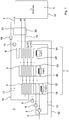
- Each compressor is followed by a gas flow path, which forms a compression stage together with the respective compressor.
- the compressor 3 the gas flow path 11 is connected downstream of the compressor 8, the gas flow path 12 is followed and the compressor 9, the gas flow path 13 is connected downstream.
- the gas flow path 11 connects the output of the compressor 3 to the input of the compressor 8
- the gas flow path 12 connects the output of the compressor 8 to the inlet of the compressor 9,
- the gas flow path 13 connects the outlet of the compressor 9 to the inlet "in" of the pressure vessel 10
- the input of the compressor 3 is open to the environment.
- the heat storage assembly 7 is connected, wherein the Heat storage 4, 5 and 6 in the flow direction of the air 1 in each of the gas flow paths 11, 12 and 13 have the same order.
Landscapes
- Engineering & Computer Science (AREA)
- Chemical & Material Sciences (AREA)
- Combustion & Propulsion (AREA)
- Mechanical Engineering (AREA)
- General Engineering & Computer Science (AREA)
- Filling Or Discharging Of Gas Storage Vessels (AREA)
- Engine Equipment That Uses Special Cycles (AREA)
Claims (10)
- Dispositif pour l'accumulation provisoire de gaz et de chaleur, avec au moins un récipient sous pression (10), plusieurs compresseurs (3, 8, 9), au moyen desquels un gaz (1) peut être comprimé, plusieurs étages de compression branchés en série, qui comprennent chacun un des compresseurs (3, 8, 9) et un trajet d'écoulement de gaz (11, 12, 13) disposé en aval de celui-ci, le récipient sous pression (10), dans lequel le gaz (1) comprimé au moyen des compresseurs (3, 8, 9) peut être accumulé, étant disposé en aval du dernier des étages de compression, et une disposition d'accumulateurs de chaleur (7), comprenant plusieurs accumulateurs de chaleur (4, 5, 6), au moyen de laquelle la chaleur de compression produite par la compression du gaz (1) peut être accumulée, caractérisé en ce que la disposition d'accumulateurs de chaleur (7) est disposée dans le trajet d'écoulement de gaz (11, 12, 13) de chaque étage de compression, un ordre d'accumulateurs de chaleur est attribué aux accumulateurs de chaleur (4, 5, 6) et les accumulateurs de chaleur (4, 5, 6) sont traversés successivement par le trajet d'écoulement de gaz (11, 12, 13) de chaque étage de compression dans l'ordre des accumulateurs de chaleur, une température minimale prédéterminée est attribuée à chaque accumulateur de chaleur (4, 5, 6) et la disposition d'accumulateurs de chaleur (7) comprend au moins un dispositif de chauffage (18, 19, 20), au moyen duquel chaque accumulateur de chaleur (4, 5, 6) peut être chauffé à la température minimale qui lui est attribuée, les températures minimales correspondant aux accumulateurs de chaleur (4, 5, 6) diminuant dans l'ordre des accumulateurs de chaleur.
- Dispositif selon l'une des revendications précédentes, caractérisé en ce que chaque accumulateur de chaleur (4, 5, 6) comprend un fluide accumulateur de chaleur (22, 23, 24) dans lequel une partie de la chaleur de compression peut être accumulée.
- Dispositif selon la revendication 2,
caractérisé en ce que la température minimale prédéterminée du premier de l'ordre des accumulateurs de chaleur (4) est d'au moins 100 °C et son fluide accumulateur de chaleur (22) est la glycérine. - Dispositif selon la revendication 3,
caractérisé en ce que la température minimale prédéterminée du ou de chacun des accumulateurs de chaleur (5, 6) disposés en aval du premier de l'ordre des accumulateurs de chaleur (4), est inférieure à 100 °C et leur fluide accumulateur de chaleur (23, 24) est l'eau. - Dispositif selon l'une des revendications précédentes, caractérisé en ce que le gaz (1) est l'air.
- Dispositif selon l'une des revendications précédentes, caractérisé par plusieurs dispositifs d'expansion (14, 15), au moyen desquels le gaz peut être dilaté, et plusieurs étages d'expansion disposés en série, qui comprennent chacun un des dispositifs d'expansion (14, 15) et un trajet d'écoulement de gaz (16, 17) disposé en amont de ceux-ci, le récipient sous pression (10) étant disposé en amont du premier des étages d'expansion, la disposition d'accumulateurs de chaleur (7) étant disposée dans le trajet d'écoulement du gaz (16, 17) de chaque étage d'expansion et les accumulateurs de chaleur (4, 5, 6) étant traversés par le trajet d'écoulement de gaz (16, 17) de chaque étage d'expansion successivement dans l'ordre inverse des accumulateurs de chaleur.
- Dispositif selon la revendication 6, caractérisé en ce que, dans le trajet d'écoulement du gaz (13) du dernier étage de compression, entre la disposition d'accumulateurs de chaleur (7) et le récipient sous pression (10), est disposé un dispositif accumulateur de froid (21), qui est disposé en outre en aval de chacun des dispositifs d'expansion (14, 15) et qui peut être refroidi par le froid du gaz dilaté (1), de façon à ce que, au moyen du dispositif accumulateur de froid (21), le gaz introduit dans le récipient sous pression (10) puisse être refroidi.
- Dispositif selon la revendication 7, caractérisé en ce que le dispositif accumulateur de froid (21) est disposé en outre dans le trajet d'écoulement de gaz (16) du premier étage d'expansion avant la disposition d'accumulateurs de chaleur (7), de façon à ce que le gaz introduit dans les étages d'expansion puisse être préchauffé au moyen du dispositif accumulateur de froid (21).
- Procédé d'accumulation provisoire de gaz et de chaleur, un gaz (1) étant comprimé successivement dans plusieurs étages de compression puis accumulé dans au moins un récipient sous pression (10) et la chaleur de compression produite par la compression du gaz (1) étant accumulée après chaque compression dans plusieurs accumulateurs de chaleur (4, 5, 6), caractérisé en ce qu'un ordre d'accumulateurs de chaleur est attribué aux accumulateurs de chaleur (4, 5, 6) et le gaz (1) traversant, après chaque compression, les accumulateurs de chaleur (4, 5, 6) successivement dans l'ordre des accumulateurs de chaleur, de façon à ce que la chaleur de compression soit transférée aux accumulateur de chaleur (4, 5, 6), une température minimale prédéterminée est attribuée à chaque accumulateur de chaleur (4, 5, 6) et, au moyen d'au moins un dispositif de chauffage, chaque accumulateur de chaleur (4, 5, 6) est au moins maintenu à la température minimale qui lui est attribuée, les températures minimales correspondant aux accumulateurs de chaleur diminuant dans l'ordre des accumulateurs de chaleur.
- Procédé selon la revendication 9, caractérisé en ce que le gaz (1) accumulé dans le récipient sous pression (10) est dilaté successivement dans plusieurs étages d'expansion, le gaz (1) traversant successivement, avant chaque expansion, les accumulateurs de chaleur (4, 5, 6) dans l'ordre inverse des accumulateurs de chaleur et étant ainsi chauffé.
Applications Claiming Priority (2)
| Application Number | Priority Date | Filing Date | Title |
|---|---|---|---|
| DE102014118466.1A DE102014118466B4 (de) | 2014-12-11 | 2014-12-11 | Vorrichtung und Verfahren zum vorübergehenden Speichern von Gas und Wärme |
| PCT/EP2015/075494 WO2016091475A1 (fr) | 2014-12-11 | 2015-11-02 | Dispositif et procédé pour le stockage temporaire de gaz et de chaleur |
Publications (2)
| Publication Number | Publication Date |
|---|---|
| EP3230571A1 EP3230571A1 (fr) | 2017-10-18 |
| EP3230571B1 true EP3230571B1 (fr) | 2019-10-30 |
Family
ID=54545090
Family Applications (1)
| Application Number | Title | Priority Date | Filing Date |
|---|---|---|---|
| EP15794851.4A Active EP3230571B1 (fr) | 2014-12-11 | 2015-11-02 | Dispositif et procédé pour le stockage temporaire de gaz et de chaleur |
Country Status (11)
| Country | Link |
|---|---|
| US (1) | US10690053B2 (fr) |
| EP (1) | EP3230571B1 (fr) |
| JP (1) | JP6710700B2 (fr) |
| KR (1) | KR102384815B1 (fr) |
| CN (1) | CN107002559B (fr) |
| AU (1) | AU2015359869C1 (fr) |
| CA (1) | CA2968152C (fr) |
| DE (1) | DE102014118466B4 (fr) |
| DK (1) | DK3230571T3 (fr) |
| RU (1) | RU2704591C2 (fr) |
| WO (1) | WO2016091475A1 (fr) |
Cited By (1)
| Publication number | Priority date | Publication date | Assignee | Title |
|---|---|---|---|---|
| US11591957B2 (en) | 2017-10-24 | 2023-02-28 | Tes Caes Technology Limited | Energy storage apparatus and method |
Families Citing this family (4)
| Publication number | Priority date | Publication date | Assignee | Title |
|---|---|---|---|---|
| WO2017093768A1 (fr) * | 2015-12-03 | 2017-06-08 | Cheesecake Energy Ltd. | Système de stockage d'énergie |
| DE102018002198A1 (de) * | 2018-03-19 | 2019-09-19 | Karl Naguib-Agha | Verfahren sowie Druckspeicheranlage zur Speicherung und Bereitstellung von elektrischer Energie |
| DE102019110024A1 (de) * | 2018-04-18 | 2019-10-24 | Carbon-Clean Technologies Gmbh | Verfahren zum Betreiben einer regenerativen Wärmespeicheranordnung und Wärmespeicheranordnung |
| FR3117167A1 (fr) * | 2020-12-03 | 2022-06-10 | IFP Energies Nouvelles | procédé de stockage et de récupération d’énergie avec optimisation thermique à la détente |
Citations (1)
| Publication number | Priority date | Publication date | Assignee | Title |
|---|---|---|---|---|
| WO2015150104A1 (fr) * | 2014-04-03 | 2015-10-08 | IFP Energies Nouvelles | Système de stockage de chaleur par lit fluidisé |
Family Cites Families (18)
| Publication number | Priority date | Publication date | Assignee | Title |
|---|---|---|---|---|
| DE527794C (de) * | 1926-02-07 | 1931-06-22 | Dinsing Geb | Elektrischer Waermespeicher |
| SU383859A1 (ru) * | 1970-12-11 | 1973-05-23 | Способ получения пиковой электроэнергии | |
| US3841064A (en) * | 1972-10-27 | 1974-10-15 | Edgcomb Steel Co | Aftercooler |
| DE2636417A1 (de) * | 1976-08-13 | 1978-02-16 | Bbc Brown Boveri & Cie | Anlage zum speichern und ausnutzen von energie unter verwendung von verdichteter luft |
| JPH01212892A (ja) * | 1988-02-22 | 1989-08-25 | Kawasaki Heavy Ind Ltd | 蓄熱装置 |
| RU2053398C1 (ru) * | 1992-06-16 | 1996-01-27 | Сибирский энергетический институт СО РАН | Воздухоаккумулирующая установка |
| JP2004108761A (ja) * | 2002-08-29 | 2004-04-08 | Kuraray Engineering Co Ltd | 蓄熱槽、蓄熱システム及び加熱冷却方法 |
| US7086231B2 (en) * | 2003-02-05 | 2006-08-08 | Active Power, Inc. | Thermal and compressed air storage system |
| DE102008033527A1 (de) * | 2008-07-17 | 2010-01-21 | Leithner, Reinhard, Prof. Dr. techn. | Latentwärmespeicherkaskade |
| RU2435050C2 (ru) * | 2009-03-13 | 2011-11-27 | Общество С Ограниченной Ответственностью "Центр Кортэс" | Энергоаккумулирующая установка |
| US20110094229A1 (en) * | 2009-10-27 | 2011-04-28 | Freund Sebastian W | Adiabatic compressed air energy storage system with combustor |
| US20110094231A1 (en) * | 2009-10-28 | 2011-04-28 | Freund Sebastian W | Adiabatic compressed air energy storage system with multi-stage thermal energy storage |
| US20110100010A1 (en) * | 2009-10-30 | 2011-05-05 | Freund Sebastian W | Adiabatic compressed air energy storage system with liquid thermal energy storage |
| DE102010050428A1 (de) * | 2010-11-04 | 2012-05-10 | Theo Tietjen | Druckstufen-Wärme-Speicherkraftwerk bzw. Energiespeicherverfahren zum zeitweiligen Speichern von Energie in Form von Druckenergie in einem kompressiblen Medium und in Form von Wärmeenergie |
| DE102011118105A1 (de) * | 2011-11-10 | 2013-05-16 | Westinghouse Electric Germany Gmbh | Wärmespeichermodul und Wärmespeicher |
| US9766017B2 (en) * | 2012-06-15 | 2017-09-19 | Mitsubishi Electric Corporation | Heating apparatus |
| US9816378B1 (en) * | 2013-03-15 | 2017-11-14 | Harris Corporation | Pneumatic compressor/motor |
| FR3014182B1 (fr) | 2013-11-29 | 2018-11-16 | IFP Energies Nouvelles | Systeme avance de stockage d'energie par air comprime |
-
2014
- 2014-12-11 DE DE102014118466.1A patent/DE102014118466B4/de active Active
-
2015
- 2015-11-02 US US15/534,425 patent/US10690053B2/en active Active
- 2015-11-02 CA CA2968152A patent/CA2968152C/fr active Active
- 2015-11-02 EP EP15794851.4A patent/EP3230571B1/fr active Active
- 2015-11-02 JP JP2017549584A patent/JP6710700B2/ja active Active
- 2015-11-02 CN CN201580067083.9A patent/CN107002559B/zh active Active
- 2015-11-02 WO PCT/EP2015/075494 patent/WO2016091475A1/fr active Application Filing
- 2015-11-02 AU AU2015359869A patent/AU2015359869C1/en active Active
- 2015-11-02 RU RU2017120389A patent/RU2704591C2/ru active
- 2015-11-02 DK DK15794851.4T patent/DK3230571T3/da active
- 2015-11-02 KR KR1020177018771A patent/KR102384815B1/ko active IP Right Grant
Patent Citations (1)
| Publication number | Priority date | Publication date | Assignee | Title |
|---|---|---|---|---|
| WO2015150104A1 (fr) * | 2014-04-03 | 2015-10-08 | IFP Energies Nouvelles | Système de stockage de chaleur par lit fluidisé |
Cited By (1)
| Publication number | Priority date | Publication date | Assignee | Title |
|---|---|---|---|---|
| US11591957B2 (en) | 2017-10-24 | 2023-02-28 | Tes Caes Technology Limited | Energy storage apparatus and method |
Also Published As
| Publication number | Publication date |
|---|---|
| US10690053B2 (en) | 2020-06-23 |
| CN107002559B (zh) | 2019-07-09 |
| CA2968152A1 (fr) | 2016-06-16 |
| JP2018508703A (ja) | 2018-03-29 |
| CN107002559A (zh) | 2017-08-01 |
| JP6710700B2 (ja) | 2020-06-17 |
| DE102014118466B4 (de) | 2017-01-12 |
| AU2015359869B2 (en) | 2019-03-14 |
| RU2704591C2 (ru) | 2019-10-29 |
| AU2015359869C1 (en) | 2019-06-27 |
| RU2017120389A3 (fr) | 2019-03-19 |
| CA2968152C (fr) | 2023-09-19 |
| EP3230571A1 (fr) | 2017-10-18 |
| DE102014118466A1 (de) | 2016-06-16 |
| DK3230571T3 (da) | 2020-02-03 |
| WO2016091475A1 (fr) | 2016-06-16 |
| KR102384815B1 (ko) | 2022-04-07 |
| KR20170093921A (ko) | 2017-08-16 |
| RU2017120389A (ru) | 2019-01-11 |
| AU2015359869A1 (en) | 2017-06-29 |
| US20180258849A1 (en) | 2018-09-13 |
Similar Documents
| Publication | Publication Date | Title |
|---|---|---|
| EP3230571B1 (fr) | Dispositif et procédé pour le stockage temporaire de gaz et de chaleur | |
| EP2748434B1 (fr) | Installation de stockage d'énergie thermique | |
| EP2698505A1 (fr) | Procédé de chargement et de déchargement d'un accumulateur thermique et installation pour le stockage et le dépôt d'énergie thermique appropriée à ce procédé | |
| EP2574756B1 (fr) | Procédé de fonctionnement d'une centrale d'accumulation d'air comprimé adiabatique et centrale d'accumulation d'air comprimé adiabatique | |
| EP2823156B1 (fr) | Installation pour le stockage et le dépôt d'énergie thermique | |
| EP3186506B1 (fr) | Dispositif et procédé de stockage d'énergie | |
| EP2622289A1 (fr) | Pompe à chaleur | |
| WO2013110375A2 (fr) | Dispositif et procédé de production d'énergie électrique | |
| DE202005003611U1 (de) | Wärmekraftwerk mit Druckluftspeichervorrichtung zum Ausgleich fluktuierender Energieeinspeisung aus regenerativen Energiequellen | |
| DE102011108970A1 (de) | Niedertemperaturkraftwerk, sowie Verfahrenzum Betrieb desselben | |
| DE102013205266A1 (de) | Wärmekraftmaschine und Verfahren zum Betreiben einer Wärmekraftmaschine | |
| EP2825737A1 (fr) | Installation d'accumulation et de distribution d'énergie thermique au moyen d'un accumulateur de chaleur et d'un accumulateur de froid et procédé de fonctionnement de ladite installation | |
| DE102004041108B3 (de) | Vorrichtung und Verfahren zum Ausführen eines verbesserten ORC-Prozesses | |
| EP2599980A2 (fr) | Centrale électrique avec stockage de gaz sous pression | |
| DE102012217142A1 (de) | Verfahren zum Laden und Entladen eines Speichermediums in einem Wärmespeicher und Anlage zur Durchführung dieses Verfahrens | |
| WO2022101348A1 (fr) | Accumulateur d'énergie thermique pour le stockage d'énergie électrique | |
| EP2902604A1 (fr) | Procédé et dispositif de stockage d'énergie | |
| DE102016114906A1 (de) | Vorrichtung und Verfahren zum Speichern und Rückgewinnen von Energie | |
| DE102020131706A1 (de) | System und Verfahren zur Speicherung und Abgabe von elektrischer Energie mit deren Speicherung als Wärmeenergie | |
| EP3293475A1 (fr) | Procédé et appareil de stockage et de récupération d'énergie | |
| AT413734B (de) | Verfahren zur entnahme von wärme bei umgebungstemperatur | |
| DE4317947C1 (de) | Verfahren und Vorrichtungen zur Umwandlung thermischer Energie eines Mediums in mechanische Arbeit | |
| DE102009030146A1 (de) | Vorrichtung und Verfahren zur Energiespeicherung und -bereitstellung | |
| EP3599440A1 (fr) | Procédé et dispositif de génération d'un gaz | |
| WO2017220529A1 (fr) | Procédé pour accumuler un fluide de stockage et système pour accumuler un fluide de stockage |
Legal Events
| Date | Code | Title | Description |
|---|---|---|---|
| STAA | Information on the status of an ep patent application or granted ep patent |
Free format text: STATUS: THE INTERNATIONAL PUBLICATION HAS BEEN MADE |
|
| PUAI | Public reference made under article 153(3) epc to a published international application that has entered the european phase |
Free format text: ORIGINAL CODE: 0009012 |
|
| STAA | Information on the status of an ep patent application or granted ep patent |
Free format text: STATUS: REQUEST FOR EXAMINATION WAS MADE |
|
| 17P | Request for examination filed |
Effective date: 20170705 |
|
| AK | Designated contracting states |
Kind code of ref document: A1 Designated state(s): AL AT BE BG CH CY CZ DE DK EE ES FI FR GB GR HR HU IE IS IT LI LT LU LV MC MK MT NL NO PL PT RO RS SE SI SK SM TR |
|
| AX | Request for extension of the european patent |
Extension state: BA ME |
|
| DAV | Request for validation of the european patent (deleted) | ||
| DAX | Request for extension of the european patent (deleted) | ||
| GRAP | Despatch of communication of intention to grant a patent |
Free format text: ORIGINAL CODE: EPIDOSNIGR1 |
|
| STAA | Information on the status of an ep patent application or granted ep patent |
Free format text: STATUS: GRANT OF PATENT IS INTENDED |
|
| INTG | Intention to grant announced |
Effective date: 20190104 |
|
| GRAJ | Information related to disapproval of communication of intention to grant by the applicant or resumption of examination proceedings by the epo deleted |
Free format text: ORIGINAL CODE: EPIDOSDIGR1 |
|
| STAA | Information on the status of an ep patent application or granted ep patent |
Free format text: STATUS: REQUEST FOR EXAMINATION WAS MADE |
|
| GRAP | Despatch of communication of intention to grant a patent |
Free format text: ORIGINAL CODE: EPIDOSNIGR1 |
|
| STAA | Information on the status of an ep patent application or granted ep patent |
Free format text: STATUS: GRANT OF PATENT IS INTENDED |
|
| INTC | Intention to grant announced (deleted) | ||
| INTG | Intention to grant announced |
Effective date: 20190517 |
|
| GRAS | Grant fee paid |
Free format text: ORIGINAL CODE: EPIDOSNIGR3 |
|
| GRAA | (expected) grant |
Free format text: ORIGINAL CODE: 0009210 |
|
| STAA | Information on the status of an ep patent application or granted ep patent |
Free format text: STATUS: THE PATENT HAS BEEN GRANTED |
|
| AK | Designated contracting states |
Kind code of ref document: B1 Designated state(s): AL AT BE BG CH CY CZ DE DK EE ES FI FR GB GR HR HU IE IS IT LI LT LU LV MC MK MT NL NO PL PT RO RS SE SI SK SM TR |
|
| REG | Reference to a national code |
Ref country code: GB Ref legal event code: FG4D Free format text: NOT ENGLISH |
|
| REG | Reference to a national code |
Ref country code: CH Ref legal event code: EP |
|
| REG | Reference to a national code |
Ref country code: DE Ref legal event code: R096 Ref document number: 502015010816 Country of ref document: DE |
|
| REG | Reference to a national code |
Ref country code: AT Ref legal event code: REF Ref document number: 1196388 Country of ref document: AT Kind code of ref document: T Effective date: 20191115 |
|
| REG | Reference to a national code |
Ref country code: IE Ref legal event code: FG4D Free format text: LANGUAGE OF EP DOCUMENT: GERMAN |
|
| REG | Reference to a national code |
Ref country code: CH Ref legal event code: NV Representative=s name: LUCHS AND PARTNER AG PATENTANWAELTE, CH |
|
| REG | Reference to a national code |
Ref country code: DK Ref legal event code: T3 Effective date: 20200127 |
|
| REG | Reference to a national code |
Ref country code: NL Ref legal event code: FP |
|
| REG | Reference to a national code |
Ref country code: LT Ref legal event code: MG4D |
|
| PG25 | Lapsed in a contracting state [announced via postgrant information from national office to epo] |
Ref country code: LV Free format text: LAPSE BECAUSE OF FAILURE TO SUBMIT A TRANSLATION OF THE DESCRIPTION OR TO PAY THE FEE WITHIN THE PRESCRIBED TIME-LIMIT Effective date: 20191030 Ref country code: SE Free format text: LAPSE BECAUSE OF FAILURE TO SUBMIT A TRANSLATION OF THE DESCRIPTION OR TO PAY THE FEE WITHIN THE PRESCRIBED TIME-LIMIT Effective date: 20191030 Ref country code: LT Free format text: LAPSE BECAUSE OF FAILURE TO SUBMIT A TRANSLATION OF THE DESCRIPTION OR TO PAY THE FEE WITHIN THE PRESCRIBED TIME-LIMIT Effective date: 20191030 Ref country code: PL Free format text: LAPSE BECAUSE OF FAILURE TO SUBMIT A TRANSLATION OF THE DESCRIPTION OR TO PAY THE FEE WITHIN THE PRESCRIBED TIME-LIMIT Effective date: 20191030 Ref country code: NO Free format text: LAPSE BECAUSE OF FAILURE TO SUBMIT A TRANSLATION OF THE DESCRIPTION OR TO PAY THE FEE WITHIN THE PRESCRIBED TIME-LIMIT Effective date: 20200130 Ref country code: GR Free format text: LAPSE BECAUSE OF FAILURE TO SUBMIT A TRANSLATION OF THE DESCRIPTION OR TO PAY THE FEE WITHIN THE PRESCRIBED TIME-LIMIT Effective date: 20200131 Ref country code: FI Free format text: LAPSE BECAUSE OF FAILURE TO SUBMIT A TRANSLATION OF THE DESCRIPTION OR TO PAY THE FEE WITHIN THE PRESCRIBED TIME-LIMIT Effective date: 20191030 Ref country code: BG Free format text: LAPSE BECAUSE OF FAILURE TO SUBMIT A TRANSLATION OF THE DESCRIPTION OR TO PAY THE FEE WITHIN THE PRESCRIBED TIME-LIMIT Effective date: 20200130 Ref country code: PT Free format text: LAPSE BECAUSE OF FAILURE TO SUBMIT A TRANSLATION OF THE DESCRIPTION OR TO PAY THE FEE WITHIN THE PRESCRIBED TIME-LIMIT Effective date: 20200302 |
|
| PG25 | Lapsed in a contracting state [announced via postgrant information from national office to epo] |
Ref country code: HR Free format text: LAPSE BECAUSE OF FAILURE TO SUBMIT A TRANSLATION OF THE DESCRIPTION OR TO PAY THE FEE WITHIN THE PRESCRIBED TIME-LIMIT Effective date: 20191030 Ref country code: RS Free format text: LAPSE BECAUSE OF FAILURE TO SUBMIT A TRANSLATION OF THE DESCRIPTION OR TO PAY THE FEE WITHIN THE PRESCRIBED TIME-LIMIT Effective date: 20191030 Ref country code: IS Free format text: LAPSE BECAUSE OF FAILURE TO SUBMIT A TRANSLATION OF THE DESCRIPTION OR TO PAY THE FEE WITHIN THE PRESCRIBED TIME-LIMIT Effective date: 20200229 |
|
| PG25 | Lapsed in a contracting state [announced via postgrant information from national office to epo] |
Ref country code: AL Free format text: LAPSE BECAUSE OF FAILURE TO SUBMIT A TRANSLATION OF THE DESCRIPTION OR TO PAY THE FEE WITHIN THE PRESCRIBED TIME-LIMIT Effective date: 20191030 |
|
| PG25 | Lapsed in a contracting state [announced via postgrant information from national office to epo] |
Ref country code: RO Free format text: LAPSE BECAUSE OF FAILURE TO SUBMIT A TRANSLATION OF THE DESCRIPTION OR TO PAY THE FEE WITHIN THE PRESCRIBED TIME-LIMIT Effective date: 20191030 Ref country code: LU Free format text: LAPSE BECAUSE OF NON-PAYMENT OF DUE FEES Effective date: 20191102 Ref country code: EE Free format text: LAPSE BECAUSE OF FAILURE TO SUBMIT A TRANSLATION OF THE DESCRIPTION OR TO PAY THE FEE WITHIN THE PRESCRIBED TIME-LIMIT Effective date: 20191030 Ref country code: MC Free format text: LAPSE BECAUSE OF FAILURE TO SUBMIT A TRANSLATION OF THE DESCRIPTION OR TO PAY THE FEE WITHIN THE PRESCRIBED TIME-LIMIT Effective date: 20191030 Ref country code: CZ Free format text: LAPSE BECAUSE OF FAILURE TO SUBMIT A TRANSLATION OF THE DESCRIPTION OR TO PAY THE FEE WITHIN THE PRESCRIBED TIME-LIMIT Effective date: 20191030 Ref country code: ES Free format text: LAPSE BECAUSE OF FAILURE TO SUBMIT A TRANSLATION OF THE DESCRIPTION OR TO PAY THE FEE WITHIN THE PRESCRIBED TIME-LIMIT Effective date: 20191030 |
|
| REG | Reference to a national code |
Ref country code: DE Ref legal event code: R097 Ref document number: 502015010816 Country of ref document: DE |
|
| REG | Reference to a national code |
Ref country code: BE Ref legal event code: MM Effective date: 20191130 |
|
| PG25 | Lapsed in a contracting state [announced via postgrant information from national office to epo] |
Ref country code: SK Free format text: LAPSE BECAUSE OF FAILURE TO SUBMIT A TRANSLATION OF THE DESCRIPTION OR TO PAY THE FEE WITHIN THE PRESCRIBED TIME-LIMIT Effective date: 20191030 Ref country code: IT Free format text: LAPSE BECAUSE OF FAILURE TO SUBMIT A TRANSLATION OF THE DESCRIPTION OR TO PAY THE FEE WITHIN THE PRESCRIBED TIME-LIMIT Effective date: 20191030 Ref country code: SM Free format text: LAPSE BECAUSE OF FAILURE TO SUBMIT A TRANSLATION OF THE DESCRIPTION OR TO PAY THE FEE WITHIN THE PRESCRIBED TIME-LIMIT Effective date: 20191030 |
|
| PLBE | No opposition filed within time limit |
Free format text: ORIGINAL CODE: 0009261 |
|
| STAA | Information on the status of an ep patent application or granted ep patent |
Free format text: STATUS: NO OPPOSITION FILED WITHIN TIME LIMIT |
|
| 26N | No opposition filed |
Effective date: 20200731 |
|
| PG25 | Lapsed in a contracting state [announced via postgrant information from national office to epo] |
Ref country code: IE Free format text: LAPSE BECAUSE OF NON-PAYMENT OF DUE FEES Effective date: 20191102 |
|
| PG25 | Lapsed in a contracting state [announced via postgrant information from national office to epo] |
Ref country code: SI Free format text: LAPSE BECAUSE OF FAILURE TO SUBMIT A TRANSLATION OF THE DESCRIPTION OR TO PAY THE FEE WITHIN THE PRESCRIBED TIME-LIMIT Effective date: 20191030 Ref country code: BE Free format text: LAPSE BECAUSE OF NON-PAYMENT OF DUE FEES Effective date: 20191130 |
|
| PG25 | Lapsed in a contracting state [announced via postgrant information from national office to epo] |
Ref country code: CY Free format text: LAPSE BECAUSE OF FAILURE TO SUBMIT A TRANSLATION OF THE DESCRIPTION OR TO PAY THE FEE WITHIN THE PRESCRIBED TIME-LIMIT Effective date: 20191030 |
|
| PG25 | Lapsed in a contracting state [announced via postgrant information from national office to epo] |
Ref country code: MT Free format text: LAPSE BECAUSE OF FAILURE TO SUBMIT A TRANSLATION OF THE DESCRIPTION OR TO PAY THE FEE WITHIN THE PRESCRIBED TIME-LIMIT Effective date: 20191030 Ref country code: HU Free format text: LAPSE BECAUSE OF FAILURE TO SUBMIT A TRANSLATION OF THE DESCRIPTION OR TO PAY THE FEE WITHIN THE PRESCRIBED TIME-LIMIT; INVALID AB INITIO Effective date: 20151102 |
|
| PG25 | Lapsed in a contracting state [announced via postgrant information from national office to epo] |
Ref country code: TR Free format text: LAPSE BECAUSE OF FAILURE TO SUBMIT A TRANSLATION OF THE DESCRIPTION OR TO PAY THE FEE WITHIN THE PRESCRIBED TIME-LIMIT Effective date: 20191030 |
|
| PG25 | Lapsed in a contracting state [announced via postgrant information from national office to epo] |
Ref country code: MK Free format text: LAPSE BECAUSE OF FAILURE TO SUBMIT A TRANSLATION OF THE DESCRIPTION OR TO PAY THE FEE WITHIN THE PRESCRIBED TIME-LIMIT Effective date: 20191030 |
|
| PGFP | Annual fee paid to national office [announced via postgrant information from national office to epo] |
Ref country code: NL Payment date: 20221118 Year of fee payment: 8 Ref country code: GB Payment date: 20221110 Year of fee payment: 8 Ref country code: FR Payment date: 20221110 Year of fee payment: 8 Ref country code: DK Payment date: 20221122 Year of fee payment: 8 Ref country code: AT Payment date: 20221110 Year of fee payment: 8 |
|
| PGFP | Annual fee paid to national office [announced via postgrant information from national office to epo] |
Ref country code: CH Payment date: 20221124 Year of fee payment: 8 |
|
| PGFP | Annual fee paid to national office [announced via postgrant information from national office to epo] |
Ref country code: DE Payment date: 20221129 Year of fee payment: 8 |