EP3230571B1 - Device and method for temporarily storing gas and heat - Google Patents
Device and method for temporarily storing gas and heat Download PDFInfo
- Publication number
- EP3230571B1 EP3230571B1 EP15794851.4A EP15794851A EP3230571B1 EP 3230571 B1 EP3230571 B1 EP 3230571B1 EP 15794851 A EP15794851 A EP 15794851A EP 3230571 B1 EP3230571 B1 EP 3230571B1
- Authority
- EP
- European Patent Office
- Prior art keywords
- heat
- gas
- expansion
- compression
- heat storage
- Prior art date
- Legal status (The legal status is an assumption and is not a legal conclusion. Google has not performed a legal analysis and makes no representation as to the accuracy of the status listed.)
- Active
Links
- 238000000034 method Methods 0.000 title claims description 38
- 238000007906 compression Methods 0.000 claims description 90
- 230000006835 compression Effects 0.000 claims description 90
- PEDCQBHIVMGVHV-UHFFFAOYSA-N Glycerine Chemical compound OCC(O)CO PEDCQBHIVMGVHV-UHFFFAOYSA-N 0.000 claims description 49
- 238000010438 heat treatment Methods 0.000 claims description 18
- 235000011187 glycerol Nutrition 0.000 claims description 17
- 238000011144 upstream manufacturing Methods 0.000 claims description 8
- XLYOFNOQVPJJNP-UHFFFAOYSA-N water Substances O XLYOFNOQVPJJNP-UHFFFAOYSA-N 0.000 claims description 7
- 239000007788 liquid Substances 0.000 claims description 2
- 238000005338 heat storage Methods 0.000 description 170
- 239000007789 gas Substances 0.000 description 162
- 238000003860 storage Methods 0.000 description 31
- 239000002826 coolant Substances 0.000 description 20
- 238000001816 cooling Methods 0.000 description 9
- 238000011161 development Methods 0.000 description 7
- 230000018109 developmental process Effects 0.000 description 7
- 238000004146 energy storage Methods 0.000 description 4
- 238000011084 recovery Methods 0.000 description 4
- HGINCPLSRVDWNT-UHFFFAOYSA-N Acrolein Chemical compound C=CC=O HGINCPLSRVDWNT-UHFFFAOYSA-N 0.000 description 3
- 238000009413 insulation Methods 0.000 description 3
- 239000012782 phase change material Substances 0.000 description 3
- 238000009835 boiling Methods 0.000 description 2
- 230000003247 decreasing effect Effects 0.000 description 2
- 238000002347 injection Methods 0.000 description 2
- 239000007924 injection Substances 0.000 description 2
- 238000004519 manufacturing process Methods 0.000 description 2
- 239000000463 material Substances 0.000 description 2
- 238000002844 melting Methods 0.000 description 2
- 230000008018 melting Effects 0.000 description 2
- 239000002245 particle Substances 0.000 description 2
- 229920002545 silicone oil Polymers 0.000 description 2
- 238000012546 transfer Methods 0.000 description 2
- VYPSYNLAJGMNEJ-UHFFFAOYSA-N Silicium dioxide Chemical compound O=[Si]=O VYPSYNLAJGMNEJ-UHFFFAOYSA-N 0.000 description 1
- 229910021536 Zeolite Inorganic materials 0.000 description 1
- 239000002551 biofuel Substances 0.000 description 1
- 238000006243 chemical reaction Methods 0.000 description 1
- 238000012937 correction Methods 0.000 description 1
- HNPSIPDUKPIQMN-UHFFFAOYSA-N dioxosilane;oxo(oxoalumanyloxy)alumane Chemical compound O=[Si]=O.O=[Al]O[Al]=O HNPSIPDUKPIQMN-UHFFFAOYSA-N 0.000 description 1
- 238000002474 experimental method Methods 0.000 description 1
- 230000002349 favourable effect Effects 0.000 description 1
- 238000012432 intermediate storage Methods 0.000 description 1
- 238000012423 maintenance Methods 0.000 description 1
- 230000005855 radiation Effects 0.000 description 1
- 230000001172 regenerating effect Effects 0.000 description 1
- 239000000741 silica gel Substances 0.000 description 1
- 229910002027 silica gel Inorganic materials 0.000 description 1
- 239000000779 smoke Substances 0.000 description 1
- 239000000243 solution Substances 0.000 description 1
- 238000001179 sorption measurement Methods 0.000 description 1
- 239000004575 stone Substances 0.000 description 1
- 239000011232 storage material Substances 0.000 description 1
- 239000000126 substance Substances 0.000 description 1
- 231100000331 toxic Toxicity 0.000 description 1
- 230000002588 toxic effect Effects 0.000 description 1
- 239000002918 waste heat Substances 0.000 description 1
- 239000002699 waste material Substances 0.000 description 1
- 239000010457 zeolite Substances 0.000 description 1
Images
Classifications
-
- F—MECHANICAL ENGINEERING; LIGHTING; HEATING; WEAPONS; BLASTING
- F02—COMBUSTION ENGINES; HOT-GAS OR COMBUSTION-PRODUCT ENGINE PLANTS
- F02C—GAS-TURBINE PLANTS; AIR INTAKES FOR JET-PROPULSION PLANTS; CONTROLLING FUEL SUPPLY IN AIR-BREATHING JET-PROPULSION PLANTS
- F02C6/00—Plural gas-turbine plants; Combinations of gas-turbine plants with other apparatus; Adaptations of gas- turbine plants for special use
- F02C6/14—Gas-turbine plants having means for storing energy, e.g. for meeting peak loads
- F02C6/16—Gas-turbine plants having means for storing energy, e.g. for meeting peak loads for storing compressed air
-
- F—MECHANICAL ENGINEERING; LIGHTING; HEATING; WEAPONS; BLASTING
- F28—HEAT EXCHANGE IN GENERAL
- F28D—HEAT-EXCHANGE APPARATUS, NOT PROVIDED FOR IN ANOTHER SUBCLASS, IN WHICH THE HEAT-EXCHANGE MEDIA DO NOT COME INTO DIRECT CONTACT
- F28D20/00—Heat storage plants or apparatus in general; Regenerative heat-exchange apparatus not covered by groups F28D17/00 or F28D19/00
- F28D20/0034—Heat storage plants or apparatus in general; Regenerative heat-exchange apparatus not covered by groups F28D17/00 or F28D19/00 using liquid heat storage material
-
- F—MECHANICAL ENGINEERING; LIGHTING; HEATING; WEAPONS; BLASTING
- F28—HEAT EXCHANGE IN GENERAL
- F28D—HEAT-EXCHANGE APPARATUS, NOT PROVIDED FOR IN ANOTHER SUBCLASS, IN WHICH THE HEAT-EXCHANGE MEDIA DO NOT COME INTO DIRECT CONTACT
- F28D20/00—Heat storage plants or apparatus in general; Regenerative heat-exchange apparatus not covered by groups F28D17/00 or F28D19/00
- F28D2020/0004—Particular heat storage apparatus
-
- Y—GENERAL TAGGING OF NEW TECHNOLOGICAL DEVELOPMENTS; GENERAL TAGGING OF CROSS-SECTIONAL TECHNOLOGIES SPANNING OVER SEVERAL SECTIONS OF THE IPC; TECHNICAL SUBJECTS COVERED BY FORMER USPC CROSS-REFERENCE ART COLLECTIONS [XRACs] AND DIGESTS
- Y02—TECHNOLOGIES OR APPLICATIONS FOR MITIGATION OR ADAPTATION AGAINST CLIMATE CHANGE
- Y02E—REDUCTION OF GREENHOUSE GAS [GHG] EMISSIONS, RELATED TO ENERGY GENERATION, TRANSMISSION OR DISTRIBUTION
- Y02E20/00—Combustion technologies with mitigation potential
- Y02E20/14—Combined heat and power generation [CHP]
-
- Y—GENERAL TAGGING OF NEW TECHNOLOGICAL DEVELOPMENTS; GENERAL TAGGING OF CROSS-SECTIONAL TECHNOLOGIES SPANNING OVER SEVERAL SECTIONS OF THE IPC; TECHNICAL SUBJECTS COVERED BY FORMER USPC CROSS-REFERENCE ART COLLECTIONS [XRACs] AND DIGESTS
- Y02—TECHNOLOGIES OR APPLICATIONS FOR MITIGATION OR ADAPTATION AGAINST CLIMATE CHANGE
- Y02E—REDUCTION OF GREENHOUSE GAS [GHG] EMISSIONS, RELATED TO ENERGY GENERATION, TRANSMISSION OR DISTRIBUTION
- Y02E60/00—Enabling technologies; Technologies with a potential or indirect contribution to GHG emissions mitigation
- Y02E60/14—Thermal energy storage
-
- Y—GENERAL TAGGING OF NEW TECHNOLOGICAL DEVELOPMENTS; GENERAL TAGGING OF CROSS-SECTIONAL TECHNOLOGIES SPANNING OVER SEVERAL SECTIONS OF THE IPC; TECHNICAL SUBJECTS COVERED BY FORMER USPC CROSS-REFERENCE ART COLLECTIONS [XRACs] AND DIGESTS
- Y02—TECHNOLOGIES OR APPLICATIONS FOR MITIGATION OR ADAPTATION AGAINST CLIMATE CHANGE
- Y02E—REDUCTION OF GREENHOUSE GAS [GHG] EMISSIONS, RELATED TO ENERGY GENERATION, TRANSMISSION OR DISTRIBUTION
- Y02E60/00—Enabling technologies; Technologies with a potential or indirect contribution to GHG emissions mitigation
- Y02E60/16—Mechanical energy storage, e.g. flywheels or pressurised fluids
Definitions
- the invention relates to a device for temporarily storing gas and heat, comprising at least one pressure vessel, a plurality of compressors, by means of which a gas is compressible, a plurality of series-connected compression stages, each comprising one of the compressor and a gas flow path downstream therefrom, one of the last Compression stages of the pressure vessel is connected downstream, in which the compressed gas by means of the compressor can be stored, and a plurality of heat storage comprising heat storage device, by means of which by the compression of the gas generated heat of compression can be stored.
- the invention further relates to a method for temporarily storing gas and heat, wherein a gas is sequentially compressed in a plurality of compression stages and then stored in at least one pressure vessel, and wherein compression heat generated by the compression of the gas is stored in a plurality of heat stores after each compression.
- the DE 10 2010 050 428 A1 discloses a pressure stage heat storage power plant for temporarily storing energy in the form of pressure energy in a compressible medium in a pressure accumulator and in the form of heat energy, with at least one injection pressure stage connected in series with at least one compression device and at least one heat exchange device and at least one discharge pressure stage connected in series with at least one heat exchange device and at least one expansion device, wherein a number of the injection pressure stages are different from a number the Aus Schweizer-pressure levels is.
- US 2011/0094231 A1 and DE 10 2008 033 527 A1 further storage systems are described.
- the content of the font WO 2015/150104 A1 is considered as state of the art under Article 54 (3) EPC.
- the invention therefore particularly aims at an adiabatic compressed air storage power plant (Adiabatic Compressed Air Energy Storage, ACAES).
- ACAES Adiabatic Compressed Air Energy Storage
- the adjective adiabatic here is not strictly in the thermodynamic sense to understand (no heat exchange with the environment), but to mean that the resulting heat during compression should be recovered as much as possible.
- high-temperature heat storage are in principle unsuitable for longer periods, as they are basically desirable in energy storage.
- a known high-temperature accumulator suffers from the fact that the high temperature and pressure differences mentioned above mechanically decompose the storage material (for example stone) and the resulting particles can sandblast the turbine blades during expansion.
- the gas and heat storage device comprises a or at least one pressure vessel, a plurality of compressors, by means of which a gas is compressible, a plurality of series-connected Compression stages, each comprising one of the compressor and a gas flow path downstream thereof, one of the last of the compression stages of the pressure vessel is connected downstream, in which the compressor-compressed gas can be stored, and a plurality of heat storage comprising heat storage arrangement, by means of which by compressing the gas generated heat of compression can be stored, wherein the heat storage arrangement is connected in the gas flow path of each compression stage, the heat storage is assigned a heat storage order and the heat storage are sequentially passed through the gas flow path of each compression stage, in particular with respect to the respective gas flow direction in the heat storage order. Compression heat is thus preferably in each compression stage, in particular stepwise, deliverable to the heat storage.
- a series connection of the heat accumulators is connected in the gas flow path of each compression stage, wherein the heat accumulators in each of these gas flow paths are connected in series in the same sequence.
- the heat storage arrangement thus forms each compressor downstream step heat storage, the stages are formed by the heat storage.
- the temperatures of the heat storage in the heat storage sequence decrease.
- the heat storage device is operable at low temperature and is preferably also operated at low temperature.
- the pressure vessel is preferably not thermally insulated from the environment.
- the gas stored in the pressure vessel has ambient temperature or approximately ambient temperature.
- the pressure vessel may, for example, include a plurality of pressure vessels connected in series and / or be composed of these.
- the predetermined minimum temperature of the series-sequential heat accumulator is 100 ° C, approximately 100 ° C, at least 100 ° C and / or more than 100 ° C.
- the heat storage medium of the sequence-sequential heat storage glycerol also called glycerol.
- glycerol is used as the heat storage medium of the sequence-first heat accumulator.
- Glycerol empirical formula: C 3 H 8 O 3
- Q denotes the amount of heat supplied to or withdrawn from the heat storage medium
- m the mass of the heat storage medium
- c p the heat capacity of the heat storage medium
- ⁇ the density of the heat storage medium
- ⁇ T the difference between the initial and final temperature of the heat storage medium.
- the thermal conductivity of glycerol (0.286 W / mK) is also about twice as high as for silicone oil. Therefore, the relatively environmentally friendly glycerin is a relatively well-suited heat storage medium.
- the one or more of the or at least one of the compressors also forms or forms in particular one or in each case also an expansion device by means of which the gas is expandable.
- the or each compression stage, the compressor is also designed as an expansion device, also forms an expansion stage.
- a trained as an expansion device compressor is referred to, for example, as a combined compression and expansion machine.
- a combined compression and expansion machine includes, for example, an im Cylinder head converted two-stroke diesel engine, which operates for storage or compression driven by an electric motor as a compressor and generates compressed air. When regenerating or expanding it works as a compressed air motor and the electric motor is in particular an electric generator. This allows simple and compact systems. Turbine compressors are also feasible.
- the expansion path agrees wholly or partly or at least partially with the compression path, in particular if at least one of the compressors is designed as an expansion device.
- the expansion path is separated from the compression path, in particular when the compressors and the expansion device or expansion devices form separate and / or different devices and / or machines.
- the pressure vessel can be filled with the gas through the compressors and / or compression stages.
- the pressure vessel is filled with the gas through the compression stages.
- the pressure vessel is preferably emptied by the expansion stage or the expansion stages.
- the pressure vessel is emptied by the expansion stage or the expansion stages.
- the pressure vessel is filled with compressed gas in the first process stage before the compressed gas stored in the pressure vessel is expanded in the second process stage.
- the process stages do not run simultaneously, but successively. For example, there may be a longer period of, for example, several hours between the process stages.
- the compression stages are not contemporaneous with the expansion stage or the expansion stages, but successively in operation.
- the cold storage device uses, in particular as a low-temperature heat storage, the cold of the expanded gas behind the expansion devices first to lower the temperature of the coolant. This then removes heat (in particular residual heat) from the compressed gas behind the heat storage arrangement and cools the compressed gas in this way, in particular to below the ambient temperature.
- the compressed gas is additionally dehumidified before it enters the pressure vessel.
- the compressed gas is already preheated during expansion and / or recirculation in the cold storage device, preferably in two stages, before it passes through the heat storage assembly and passes to the expansion devices.
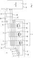
- Each compressor is followed by a gas flow path, which forms a compression stage together with the respective compressor.
- the compressor 3 the gas flow path 11 is connected downstream of the compressor 8, the gas flow path 12 is followed and the compressor 9, the gas flow path 13 is connected downstream.
- the gas flow path 11 connects the output of the compressor 3 to the input of the compressor 8
- the gas flow path 12 connects the output of the compressor 8 to the inlet of the compressor 9,
- the gas flow path 13 connects the outlet of the compressor 9 to the inlet "in" of the pressure vessel 10
- the input of the compressor 3 is open to the environment.
- the heat storage assembly 7 is connected, wherein the Heat storage 4, 5 and 6 in the flow direction of the air 1 in each of the gas flow paths 11, 12 and 13 have the same order.
Description
Die Erfindung betrifft eine Vorrichtung zum vorübergehenden Speichern von Gas und Wärme, mit wenigstens einem Druckbehälter, mehreren Verdichtern, mittels welchen ein Gas komprimierbar ist, mehreren in Reihe geschalteten Kompressionsstufen, die jeweils einen der Verdichter und einen diesem nachgeschalteten Gasströmungspfad umfassen, wobei einer reihenletzten der Kompressionsstufen der Druckbehälter nachgeschaltet ist, in welchem das mittels der Verdichter komprimierte Gas speicherbar ist, und einer mehrere Wärmespeicher umfassenden Wärmespeicheranordnung, mittels welcher durch das Komprimieren des Gases erzeugte Kompressionswärme speicherbar ist. Die Erfindung betrifft ferner ein Verfahren zum vorübergehenden Speichern von Gas und Wärme, wobei ein Gas in mehreren Kompressionsstufen nacheinander komprimiert und anschließend in wenigstens einem Druckbehälter gespeichert wird, und wobei durch das Komprimieren des Gases erzeugte Kompressionswärme nach jeder Kompression in mehreren Wärmespeichern gespeichert wird.The invention relates to a device for temporarily storing gas and heat, comprising at least one pressure vessel, a plurality of compressors, by means of which a gas is compressible, a plurality of series-connected compression stages, each comprising one of the compressor and a gas flow path downstream therefrom, one of the last Compression stages of the pressure vessel is connected downstream, in which the compressed gas by means of the compressor can be stored, and a plurality of heat storage comprising heat storage device, by means of which by the compression of the gas generated heat of compression can be stored. The invention further relates to a method for temporarily storing gas and heat, wherein a gas is sequentially compressed in a plurality of compression stages and then stored in at least one pressure vessel, and wherein compression heat generated by the compression of the gas is stored in a plurality of heat stores after each compression.
Die
Bei vielen technischen Anwendungen fällt Prozesswärme an, die abgeführt werden muss. Beispiele zu deren Nutzung sind Blockheizkraftwerke und Fernwärme. Oftmals wäre auch die Rückgewinnung der Wärme energetisch vorteilhaft. Eine direkte Rückgewinnung kann z.B. mit Wärmetauschern im Gleich- und Gegenstromverfahren erreicht werden, was dann oft hohe Energieeinsparungen ermöglicht.In many technical applications process heat is generated, which must be dissipated. Examples of their use are combined heat and power plants and district heating. Often, the recovery of heat would be energetically advantageous. Direct recovery can e.g. be achieved with heat exchangers in the DC and countercurrent process, which then often allows high energy savings.
Bei mechanischen Energiespeichern ist die Wärmerückgewinnung eine unverzichtbare Voraussetzung für akzeptable Gesamtwirkungsgrade. Ein dynamisches Verfahren als Gleich- oder Gegenstromverfahren ist hierbei jedoch nicht unbedingt zweckmäßig, weil Be- und Entladung des Energiespeichers zeitlich möglichst weit voneinander entkoppelt sein sollen. Marktübliche Wärmetauscher zeichnen sich demgegenüber aus durch ihren kontinuierlichen, gleichzeitigen parallelen oder antiparallelen Fluss. Das Fließen des Speichermediums verlangt zusätzlichen Energieaufwand für die Umwälzung, der eingespart werden kann.For mechanical energy storage, heat recovery is an indispensable prerequisite for acceptable overall efficiency. However, a dynamic method as a DC or countercurrent method is not necessarily appropriate because loading and unloading of the energy storage should be as far as possible decoupled from each other in time. Commercially available heat exchangers are characterized by their continuous, simultaneous parallel or antiparallel flow. The flow of the storage medium requires additional energy for the circulation, which can be saved.
Wenn Energie in Form von Druckluft gespeichert wird, entsteht notwendigerweise bei der Kompression Wärme (1. Hauptsatz der Thermodynamik).When energy is stored in the form of compressed air, heat necessarily arises during compression (1st law of thermodynamics).
Am einfachsten ist diese Wärme für das Beispiel eines idealen isothermen Kompressors zu berechnen. Sie beträgt theoretisch rund 1/3 der aufgewendeten Kompressionsarbeit. In der Praxis wird die Wärme meist an die Umgebung abgegeben, und die Wärmeverluste liegen meist auch noch erheblich höher, etwa bei 2/3 der aufgewendeten Kompressionsarbeit. Die Erfindung zielt daher insbesondere auf ein adiabatisches Druckluft-Speicherkraftwerk ab (engl. Adiabatic Compressed Air Energy Storage, ACAES). Dabei ist das Adjektiv adiabatisch hier nicht streng im thermodynamischen Sinne zu verstehen (gar kein Wärmeaustausch mit der Umgebung), sondern soll bedeuten, dass die bei der Kompression entstehende Wärme weitest möglich zurück gewonnen werden soll.The easiest way is to calculate this heat for the example of an ideal isothermal compressor. It is theoretically about 1/3 of the compression work done. In practice, the heat is usually released to the environment, and the heat losses are usually much higher, about 2/3 of the compression work. The invention therefore particularly aims at an adiabatic compressed air storage power plant (Adiabatic Compressed Air Energy Storage, ACAES). Here, the adjective adiabatic here is not strictly in the thermodynamic sense to understand (no heat exchange with the environment), but to mean that the resulting heat during compression should be recovered as much as possible.
Anhand der thermischen Zustandsgleichung idealer Gase p*V = n*R*T (die realistischere van-der-Waals-Gleichung bedingt lediglich eine Korrektur von circa 10%) und anhand der kalorischen Zustandsgleichung für ein zweiatomiges Gas U = 5/2*n*R*T (Luft ist zu 99% ein zweiatomiges Gas) wird ersichtlich, dass für ein Arbeitsgas in einem vorgegebenen Volumen V eine Erhöhung des Drucks p durch Erhöhung der Temperatur T oder der Stoffmenge n oder beides bewirkt wird. In jedem Fall ist dies dann gleichbedeutend mit einer Erhöhung der inneren Energie U bzw. der Enthalpie H = U + p*V des Gases. R bezeichnet die universelle Gaskonstante.Based on the equation of thermal equation of ideal gases p * V = n * R * T (the more realistic van der Waals equation requires only a correction of about 10%) and the caloric equation of state for a diatomic gas U = 5/2 * n * R * T (air is 99% diatomic gas) it will be seen that for a working gas in a given volume V, an increase in pressure p is effected by increasing the temperature T or the amount of substance n or both. In any case, this is equivalent to an increase of the internal energy U or the enthalpy H = U + p * V of the gas. R denotes the universal gas constant.
Für den Energiegewinn bzw. für den Enthalpiegewinn des Systems durch Wärmezufuhr spielt effektiv keine Rolle, ob eine solche Druckerhöhung durch Erhöhung der Molekülanzahl im Druckbehälter oder durch Temperaturerhöhung, also Erhöhung der Teilchenbewegung zustande kommt.For the energy gain or for the enthalpy gain of the system by supplying heat does not matter effectively, whether such an increase in pressure by increasing the number of molecules in the pressure vessel or by increasing the temperature, so increase the particle movement comes about.
Durch Zufuhr bzw. Rückgewinnung der Kompressionswärme werden in einem solchen quasi-adiabatischen System Gesamtwirkungsgrade möglich, die theoretisch weit über denen herkömmlicher Kompressoren und Turbinen liegen.By supplying or recovering the heat of compression in such a quasi-adiabatic system overall efficiencies are possible, which theoretically far exceed those of conventional compressors and turbines.
In der Praxis lässt sich die adiabatische Isolierung eines riesigen Hochdruckbehälters wahrscheinlich nicht verwirklichen. Denn wäre die thermische Isolierung außerhalb des Druckbehälters angebracht, dann würde sich die Behälterwand aufwärmen. Aufgrund der enormen Wärmekapazität des Druckbehälters würde dann die Kompressionswärme lediglich in einer geringfügigen Temperaturerhöhung der Behälterwand resultieren und wäre auf diesem niedrigen Temperaturniveau dann für eine praktikable, direkte Rückgewinnung weitgehend verloren. Eine innerhalb des Hochdruckbehälters angebrachte thermische Isolierung wäre dagegen enormen Druck- und Temperaturschwankungen ausgesetzt (mehrere hundert bar, mehrere hundert Kelvin), die sie auf Dauer zerstören würden. Als Konsequenz sollte sich der Hochdruckbehälter auf dem Temperaturniveau seiner Umgebung befinden.In practice, the adiabatic insulation of a huge high pressure vessel is unlikely to be realized. Because if the thermal insulation were mounted outside the pressure vessel, then the vessel wall would warm up. Due to the enormous heat capacity of the pressure vessel then the heat of compression would result only in a slight increase in temperature of the container wall and would be largely lost at this low temperature level for a practical, direct recovery. On the other hand, thermal insulation placed inside the high-pressure vessel would be subject to enormous fluctuations in pressure and temperature (several hundred bars, several hundred Kelvin), which would permanently destroy them. As a consequence, the high pressure vessel should be at the temperature level of its environment.
Dies bedingt eine notwendige Zwischenspeicherung der Kompressionswärme. Hierbei tritt nun ein anderes grundsätzliches Problem auf: Wärme lässt sich bei hohen Temperaturdifferenzen zwar gut übertragen und solche sind bei Wärmekraftmaschinen auch prinzipiell vorteilhaft (siehe Carnot-Wirkungsgrad), aber die Verluste durch Konvektion, Leitung und insbesondere Strahlung (proportional zur vierten Potenz der Temperatur, laut Stefan-Boltzmann-Gesetz) nehmen ebenfalls entsprechend zu.This requires a necessary intermediate storage of the heat of compression. Here is another fundamental problem: heat can be well transferred at high temperature differences and those are in principle also advantageous in heat engines (see Carnot efficiency), but the losses by convection, conduction and radiation (proportional to the fourth power of the temperature , according to Stefan Boltzmann law) are also increasing accordingly.
Daher sind Hochtemperatur-Wärmespeicher prinzipiell ungeeignet für längere Zeiträume, wie sie bei der Energiespeicherung aber grundsätzlich erwünscht sind. Ein bekannter Hochtemperaturspeicher leidet unter anderem auch darunter, dass die angesprochenen hohen Temperatur- und Druckdifferenzen das Speichermaterial (z.B. Stein) mechanisch zersetzen und die daraus entstehenden Partikel bei der Expansion die Turbinenschaufeln sandstrahlen können.Therefore, high-temperature heat storage are in principle unsuitable for longer periods, as they are basically desirable in energy storage. Among other things, a known high-temperature accumulator suffers from the fact that the high temperature and pressure differences mentioned above mechanically decompose the storage material (for example stone) and the resulting particles can sandblast the turbine blades during expansion.
Phasenwechselmaterialien bzw. Phase-Change-Materials (PCM) sind für die auftretenden Temperaturdifferenzen nicht geeignet bzw. befinden sich noch im Versuchsstadium. Sie degradieren mit der Zeit und wären nach derzeitigem Wissensstand nicht leistungsfähig genug. Auch die bekannten industriellen Adsorptionsspeicher Silikagel und Zeolith sind nicht geeignet, weil ein Großteil der Kompressionswärme unterhalb deren Entladungstemperaturen anfällt und die Wärmeübertragung ein kontinuierlicher und kein diskreter Vorgang ist. Mit diesen Materialien könnte also lediglich der relativ geringe Wärmeanteil wiedergewonnen werden, der oberhalb ihrer Entladungstemperaturen anfällt. Der überwiegende Restwärmeanteil auf niedrigerem Temperaturniveau wäre verloren.Phase change materials or phase change materials (PCM) are not suitable for the occurring temperature differences or are still in the experimental stage. They degrade over time and would not be powerful enough according to current knowledge. The known industrial adsorption storage silica gel and zeolite are not suitable because a large part of the heat of compression accumulates below their discharge temperatures and the heat transfer is a continuous and not a discrete process. With these materials, therefore, only the relatively small proportion of heat could be recovered be obtained above their discharge temperatures. The overwhelming residual heat content at a lower temperature level would be lost.
Ein Ausweg könnte ein mehrstufiger Niedrigtemperatur-Wärmespeicher sein. Ein derart konstruiertes adiabatisches bzw. quasi-adiabatisches Druckluft-Speicherkraftwerk könnte dann nicht an den Carnot-Wirkungsgrad gebunden sein, was sich im Gedankenversuch nachvollziehen lässt, indem der Kompressor innerhalb des adiabatisch isolierten Druckgefäßes anordnet wird. Dann müsste seine Abwärme auf das Arbeitsgas übergehen, sodass theoretisch die Energie des Kompressors vollständig nutzbar wäre.A way out could be a multi-stage low temperature heat storage. Such a constructed adiabatic or quasi-adiabatic compressed air storage power plant could then not be bound to the Carnot efficiency, which can be understood in the thought experiment by the compressor is arranged within the adiabatically insulated pressure vessel. Then its waste heat would have to be transferred to the working gas, so theoretically the energy of the compressor would be fully usable.
Der Erfindung liegt somit die Aufgabe zugrunde, eine Vorrichtung und ein Verfahren der eingangs genannten Art derart weiterzubilden, dass möglichst viel Kompressionswärme in der Wärmespeicheranordnung speicherbar ist.The invention is therefore based on the object, a device and a method of the type mentioned in such a way that as much heat of compression in the heat storage device can be stored.
Diese Aufgabe wird erfindungsgemäß durch eine Vorrichtung nach Anspruch 1 und durch ein Verfahren nach Anspruch 9 gelöst. Bevorzugte Weiterbildungen der Erfindung sind in den Unteransprüchen und in der nachfolgenden Beschreibung gegeben.This object is achieved by a device according to
Die erfindungsgemäße Vorrichtung zum vorübergehenden Speichern von Gas und Wärme weist einen oder wenigstens einen Druckbehälter, mehrere Verdichter, mittels welchen ein Gas komprimierbar ist, mehrere in Reihe geschaltete Kompressionsstufen, die jeweils einen der Verdichter und einen diesem nachgeschalteten Gasströmungspfad umfassen, wobei einer reihenletzten der Kompressionsstufen der Druckbehälter nachgeschaltet ist, in welchem das mittels der Verdichter komprimierte Gas speicherbar ist, und eine mehrere Wärmespeicher umfassende Wärmespeicheranordnung auf, mittels welcher durch das Komprimieren des Gases erzeugte Kompressionswärme speicherbar ist, wobei die Wärmespeicheranordnung in den Gasströmungspfad jeder Kompressionsstufe geschaltet ist, den Wärmespeichern eine Wärmespeicherreihenfolge zugeordnet ist und die Wärmespeicher von dem Gasströmungspfad jeder Kompressionsstufe, insbesondere bezüglich der jeweiligen Gasströmungsrichtung, in der Wärmespeicherreihenfolge nacheinander durchlaufen sind oder werden. Bevorzugt ist Kompressionswärme somit in jeder Kompressionsstufe, insbesondere stufenweise, an die Wärmespeicher abgebbar.The gas and heat storage device according to the invention comprises a or at least one pressure vessel, a plurality of compressors, by means of which a gas is compressible, a plurality of series-connected Compression stages, each comprising one of the compressor and a gas flow path downstream thereof, one of the last of the compression stages of the pressure vessel is connected downstream, in which the compressor-compressed gas can be stored, and a plurality of heat storage comprising heat storage arrangement, by means of which by compressing the gas generated heat of compression can be stored, wherein the heat storage arrangement is connected in the gas flow path of each compression stage, the heat storage is assigned a heat storage order and the heat storage are sequentially passed through the gas flow path of each compression stage, in particular with respect to the respective gas flow direction in the heat storage order. Compression heat is thus preferably in each compression stage, in particular stepwise, deliverable to the heat storage.
Gemäß der Erfindung ist in den Gasströmungspfad jeder Kompressionsstufe eine Reihenschaltung der Wärmespeicher geschaltet, wobei die Wärmespeicher in jedem dieser Gasströmungspfade in derselben Reihenfolge hintereinander geschaltet sind. Die Wärmespeicheranordnung bildet somit einen jedem Verdichter nachgeschalteten Stufenwärmespeicher, dessen Stufen durch die Wärmespeicher gebildet sind. Bevorzugt nehmen dabei die Temperaturen der Wärmespeicher in der Wärmespeicherreihenfolge ab. Durch die erfindungsgemäße Vorrichtung ist ein deutlich höherer Anteil der Kompressionswärme in der Wärmespeicheranordnung speicherbar als bei herkömmlichen Lösungen. Insbesondere ist die Wärmespeicheranordnung bei Niedrigtemperatur betreibbar und wird vorzugsweise auch bei Niedrigtemperatur betrieben.According to the invention, a series connection of the heat accumulators is connected in the gas flow path of each compression stage, wherein the heat accumulators in each of these gas flow paths are connected in series in the same sequence. The heat storage arrangement thus forms each compressor downstream step heat storage, the stages are formed by the heat storage. Preferably, the temperatures of the heat storage in the heat storage sequence decrease. By the device according to the invention is a much higher proportion of Heat of compression in the heat storage arrangement storable than in conventional solutions. In particular, the heat storage device is operable at low temperature and is preferably also operated at low temperature.
Die Anzahl der Kompressionsstufen beträgt bevorzugt zwei, wenigstens zwei, drei oder wenigstens drei. Insbesondere entspricht die Anzahl der Verdichter der Anzahl der Kompressionsstufen. Vorzugsweise umfasst jede Kompressionsstufe genau einen der Verdichter. Bevorzugt ist jeder Verdichter genau einer der Kompressionsstufen zugeordnet und/oder in dieser vorgesehen. Die Wärmespeicheranordnung und/oder die Wärmespeicher umfassen insbesondere keine Verdichter.The number of compression stages is preferably two, at least two, three or at least three. In particular, the number of compressors corresponds to the number of compression stages. Preferably, each compression stage comprises exactly one of the compressors. Preferably, each compressor is assigned to exactly one of the compression stages and / or provided in this. The heat storage arrangement and / or the heat storage in particular comprise no compressor.
Jeder Verdichter kann z.B. auch als Kompressor oder Kompressionsmaschine bezeichnet werden. Beispielsweise ist jeder Verdichter ein Turboverdichter, ein Schraubenverdichter oder ein Kolbenverdichter.Each compressor can e.g. Also referred to as a compressor or compression machine. For example, each compressor is a turbo-compressor, a screw compressor or a piston compressor.
Der Druckbehälter ist bevorzugt gegenüber der Umgebung nicht thermisch isoliert. Vorzugsweise weist das in dem Druckbehälter gespeicherte Gas Umgebungstemperatur oder näherungsweise Umgebungstemperatur auf. Der Druckbehälter kann z.B. auch mehrere hintereinander geschaltete Druckbehältnisse umfassen und/oder aus diesen zusammengesetzt sein.The pressure vessel is preferably not thermally insulated from the environment. Preferably, the gas stored in the pressure vessel has ambient temperature or approximately ambient temperature. The pressure vessel may, for example, include a plurality of pressure vessels connected in series and / or be composed of these.
Bevorzugt sind die Wärmspeicher thermisch voneinander und/oder gegenüber der Umgebung isoliert. Somit kann verhindert werden, dass sich ein thermisches Gleichgewicht unter den Wärmespeichern einstellt.The heat accumulators are preferably thermally insulated from one another and / or from the environment. Thus, it can be prevented that sets a thermal equilibrium among the heat accumulators.
Erfindungsgemäss ist jedem Wärmespeicher eine vorgegebene Mindesttemperatur zugeordnet, und die Wärmespeicheranordnung weist wenigstens eine Heizvorrichtung auf, mittels welcher jeder Wärmespeicher auf die ihm zugeordnete Mindesttemperatur erwärmbar ist, wobei die den Wärmespeichern zugeordneten Mindesttemperaturen in der Wärmespeicherreihenfolge abnehmen.According to the invention, each heat storage device is assigned a predetermined minimum temperature, and the heat storage arrangement has at least one heating device, by means of which each heat storage device can be heated to its associated minimum temperature, the minimum temperatures associated with the heat storage devices decreasing in the heat storage sequence.
Hierdurch kann sichergestellt werden, dass jeder Wärmespeicher zumindest die ihm zugeordnete Mindesttemperatur aufweist. Bevorzugt weist jeder Wärmespeicher eine Heizvorrichtung oder eine der Heizvorrichtungen auf. Insbesondere ist jeder Wärmespeicher durch seine Heizvorrichtung auf die ihm zugeordnete Mindesttemperatur erwärmbar und/oder zumindest auf dieser Mindesttemperatur haltbar. Somit ist der und/oder ein Temperaturunterschied zwischen den Wärmespeichern erzwingbar. Insbesondere stellen die Heizvorrichtungen sicher, dass die Übertragung der Kompressionswärme in die Wärmespeicher auf den oder im Bereich der gewünschten Mindesttemperaturniveaus erfolgt. Vorteilhaft weisen die Temperaturen und/oder Mindesttemperaturen der Wärmspeicher in der Wärmespeicherreihenfolge ein Gefälle auf. Die Heizvorrichtung oder jede der Heizvorrichtungen ist insbesondere als elektrische Heizvorrichtung ausgebildet.This can ensure that each heat storage has at least the minimum temperature associated with it. Each heat accumulator preferably has a heating device or one of the heating devices. In particular, each heat accumulator can be heated by its heating device to the minimum temperature assigned to it and / or can be preserved at least at this minimum temperature. Thus, the and / or a temperature difference between the heat accumulators can be forced. In particular, the heaters ensure that the transfer of the heat of compression in the heat storage on or in the area of desired minimum temperature levels takes place. Advantageously, the temperatures and / or minimum temperatures of the heat storage in the heat storage order on a slope. The heating device or each of the heating devices is designed in particular as an electrical heating device.
Bevorzugt weist jeder Wärmespeicher ein Wärmespeichermedium auf, in welchem insbesondere ein Teil der Kompressionswärme speicherbar ist. Vorzugsweise ist jedes der Wärmspeichermedien flüssig. Vorteilhaft sind die Wärmespeicher passiv. Darunter ist insbesondere zu verstehen, dass das Wärmespeichermedium jedes Wärmespeichers nicht zirkuliert und/oder umgewälzt wird. Bevorzugt erfolgt der Eintrag der Kompressionswärme in die Wärmespeichermedien, insbesondere ausschließlich oder vornehmlich, durch Konvektion.Each heat accumulator preferably has a heat storage medium in which, in particular, part of the heat of compression can be stored. Preferably, each of the heat storage media is liquid. Advantageously, the heat storage are passive. This is to be understood in particular that the heat storage medium of each heat accumulator is not circulated and / or circulated. Preferably, the entry of the heat of compression in the heat storage media, in particular exclusively or primarily, by convection.
Gemäß einer Ausgestaltung beträgt die vorgegebene Mindesttemperatur des reihenfolgenersten Wärmspeichers 100°C, näherungsweise 100°C, wenigstens 100°C und/oder mehr als 100°C. Insbesondere ist das Wärmespeichermedium des reihenfolgenersten Wärmspeichers Glycerin (auch Glycerol genannt). Bevorzugt wird ausschließlich Glycerin als Wärmespeichermedium des reihenfolgenersten Wärmspeichers verwendet. Glycerin (Summenformel: C3H8O3) fällt z.B. als Abfallprodukt bei der Herstellung von Biotreibstoff an und ist somit relativ kostengünstig erhältlich.According to one embodiment, the predetermined minimum temperature of the series-sequential heat accumulator is 100 ° C, approximately 100 ° C, at least 100 ° C and / or more than 100 ° C. In particular, the heat storage medium of the sequence-sequential heat storage glycerol (also called glycerol). Preferably, only glycerol is used as the heat storage medium of the sequence-first heat accumulator. Glycerol (empirical formula: C 3 H 8 O 3 ) is obtained, for example, as a waste product in the production of biofuel and is thus available at relatively low cost.
Entscheidend für die Eignung als Wärmespeichermedium auf Basis der grundlegenden Gleichung Q = m*cp*ΔT = ρ*cp*V *ΔT ist das Produkt cp*ρ, also Wärmekapazität mal Dichte, welches für Glycerin (3,06*106 J/m3K) mehr als doppelt so hoch ist wie für Silikonöl (1,50*106 J/m3K) und in etwa 70% des Wertes für Wasser erreicht, der außergewöhnlich hoch ist (4,40*106 J/m3K). Dabei bezeichnen Q die dem Wärmespeichermedium zugeführte oder entzogene Wärmemenge, m die Masse des Wärmespeichermediums, cp die Wärmekapazität des Wärmespeichermediums, ρ die Dichte des Wärmespeichermediums und ΔT die Differenz von Anfangs- und Endtemperatur des Wärmespeichermediums. Die Wärmeleitfähigkeit von Glycerin (0,286 W/mK) ist ebenfalls etwa doppelt so hoch wie für Silikonöl. Daher ist das vergleichsweise umweltfreundliche Glycerin ein relativ gut geeignetes Wärmespeichermedium.Decisive for the suitability as a heat storage medium on the basis of the basic equation Q = m * cp * ΔT = ρ * cp * V * ΔT is the product c p * ρ, ie heat capacity times density, which for glycerol (3.06 * 10 6 J / m 3 K) is more than twice as high as for silicone oil (1.50 * 10 6 J / m 3 K) and reaches approximately 70% of the value for water which is exceptionally high (4,40 * 10 6 J / m 3 K). Here Q denotes the amount of heat supplied to or withdrawn from the heat storage medium, m the mass of the heat storage medium, c p the heat capacity of the heat storage medium, ρ the density of the heat storage medium and ΔT the difference between the initial and final temperature of the heat storage medium. The thermal conductivity of glycerol (0.286 W / mK) is also about twice as high as for silicone oil. Therefore, the relatively environmentally friendly glycerin is a relatively well-suited heat storage medium.
Die maximale Temperatur des reihenfolgenersten Wärmspeichers und/oder des Wärmespeichermedium des reihenfolgenersten Wärmspeichers liegt insbesondere unter 200°C. Einerseits liegt diese maximale Temperatur unter dem Siedepunkt von Glycerin (Siedepunkt von Glycerin = 290°C), andererseits tritt unterhalb einer Temperatur von 200°C keine Umwandlung von Glycerin in das giftige Acrolein (auch Acrylaldehyd genannt, Summemformel: C2H4O) ein.The maximum temperature of the sequence-closest heat accumulator and / or the heat storage medium of the series-sequential heat accumulator is in particular below 200 ° C. On the one hand, this maximum temperature is below the boiling point of glycerol (boiling point of glycerol = 290 ° C), on the other hand occurs below a temperature of 200 ° C, no conversion of glycerol in the toxic acrolein (also called acrylic aldehyde, summation formula: C 2 H 4 O) one.
Gemäß einer Weiterbildung weisen die Wärmespeicher jeweils einen Wärmespeicherbehälter auf, in den das jeweilige Wärmspeichermedium eingebracht ist. Jeder der Wärmespeicherbehälter kann offen oder geschlossen ausgebildet sein.According to a development, the heat storage in each case a heat storage tank, in which the respective heat storage medium is introduced. Each of the heat storage tanks may be open or closed.
Bevorzugt ist der Wärmespeicherbehälter des reihenfolgenersten Wärmspeichers oder zumindest der Wärmespeicherbehälter des reihenfolgenersten Wärmspeichers geschlossen ausgebildet. Hierdurch kann einer ab ca. 150°C eintretenden Rauch- und/oder Dampfentwicklung von Glycerin begegnet werden. Durch die Heizvorrichtung und/oder durch das Einhalten der Mindesttemperatur des reihenfolgenersten Wärmspeichers kann insbesondere ferner sichergestellt werden, dass der relativ hohe Schmelzpunkt von Glycerin (Schmelzpunkt von Glycerin = 18°C) im Betrieb nicht unterschritten wird.Preferably, the heat storage tank of the series-sequential heat accumulator or at least the heat storage tank of the series-sequential heat accumulator is formed closed. As a result, a occurring from about 150 ° C smoke and / or vapor development of glycerol can be encountered. In particular, it can further be ensured by the heating device and / or by the maintenance of the minimum temperature of the series-stored heat accumulator that the relatively high melting point of glycerol (melting point of glycerol = 18 ° C.) is not undershot during operation.
Jeder Wärmespeicher und/oder Wärmespeicherbehälter umfasst bevorzugt eine, wenigstens eine oder genau eine Gaszuleitung je Kompressionsstufe. Vorzugsweise verlaufen die Gaszuleitungen durch den jeweiligen Wärmespeicher und/oder Wärmespeicherbehälter hindurch und sind dabei insbesondere von dem jeweiligen Wärmespeichermedium umgeben. Beispielsweise verlaufen die Gaszuleitungen in dem jeweiligen Wärmespeicher und/oder Wärmespeicherbehälter jeweils mäanderförmig, helix- oder schraubenförmig oder geradlinig. Insbesondere sind die Gaszuleitungen jeder Kompressionsstufe in Reihe geschaltet, vorzugsweise in der Wärmespeicherreihenfolge. Bevorzugt ist die Reihenschaltung aus den Gaszuleitungen jeder Kompressionsstufe in den Gasströmungspfad der jeweiligen Kompressionsstufe geschaltet. Die Gaszuleitungen jedes Wärmespeichers und/oder Wärmespeicherbehälters sind insbesondere in dem jeweiligen Wärmspeichermedium angeordnet. Durch die Gaszuleitungen jedes Wärmespeichers und/oder Wärmespeicherbehälters ist insbesondere Wärme zwischen dem Gas und dem jeweiligen Wärmespeichermedium austauschbar.Each heat storage and / or heat storage container preferably comprises one, at least one or exactly one gas supply line per compression stage. Preferably, the gas supply lines pass through the respective heat storage and / or heat storage tank and are in particular surrounded by the respective heat storage medium. For example, the gas supply lines in the respective heat storage and / or heat storage tank each meander-shaped, helical or helical or rectilinear. In particular, the gas supply lines of each compression stage are connected in series, preferably in the heat storage order. Preferably, the series connection of the gas supply lines of each compression stage is connected in the gas flow path of the respective compression stage. The Gas supply lines of each heat accumulator and / or heat storage tank are arranged in particular in the respective heat storage medium. In particular, heat between the gas and the respective heat storage medium is exchangeable by the gas supply lines of each heat accumulator and / or heat storage tank.
Bevorzugt weist die Wärmespeicheranordnung zwei, wenigstens zwei, drei oder wenigstens drei Wärmespeicher auf. Die vorgegebene Mindesttemperatur des oder jedes dem reihenfolgenersten Wärmspeicher nachgeschalteten Wärmespeichers beträgt bevorzugt weniger als 100°C. Insbesondere ist das Wärmespeichermedium des oder jedes dem reihenfolgenersten Wärmspeicher nachgeschalteten Wärmespeichers Wasser oder Glycerin.Preferably, the heat storage arrangement comprises two, at least two, three or at least three heat storage. The predetermined minimum temperature of the or each of the series-connected heat storage downstream heat storage is preferably less than 100 ° C. In particular, the heat storage medium of the or each heat storage device connected downstream of the series-connected heat accumulator is water or glycerol.
Die Wärmespeicher sind insbesondere drucklos. Darunter ist zu verstehen, dass die Wärmespeicher und/oder die Wärmespeichermedien insbesondere Umgebungsdruck aufweisen ("drucklos" im Sinne von "ohne Überdruck" gegenüber der Umgebung).The heat storage are in particular depressurized. By this is meant that the heat storage and / or the heat storage media in particular have ambient pressure ("depressurized" in the sense of "without overpressure" relative to the environment).
Jeder Wärmespeicher kann z.B. über die Menge und/oder den Füllstand seines Wärmespeichermediums in seiner Wärmekapazität auf ein gewünschtes Maß eingestellt werden. Insbesondere ist die Wärmekapazität jedes Wärmespeichers durch Zugabe und/oder Entnahme des jeweiligen Wärmespeichermediums erhöhbar und/oder verringerbar. Beispielsweise kann somit die Betriebstemperatur des jeweiligen Wärmespeichers je nach Bedarf gesenkt und/oder erhöht werden.Each heat storage can be adjusted, for example, on the amount and / or the level of its heat storage medium in its heat capacity to a desired level. In particular, the heat capacity of each heat storage by adding and / or removal of the respective heat storage medium raisable and / or reducible. For example, thus, the operating temperature of the respective heat storage can be lowered and / or increased as needed.
Gemäß einer Weiterbildung ist das Gas Luft. Luft steht auf der Erde in der Regel überall zur Verfügung. Das komprimierte Gas kann somit auch als Druckluft bezeichnet werden. Ferner können die Verdichter auch als Druckluftkompressoren und/oder der Druckbehälter auch als Druckluftbehälter bezeichnet werden.According to a development, the gas is air. Air is usually available everywhere on earth. The compressed gas can thus also be referred to as compressed air. Furthermore, the compressors may also be referred to as compressed air compressors and / or the pressure vessel as a compressed air tank.
Jeder Verdichter ist ausgangsseitig insbesondere an den Gasströmungspfad der jeweiligen Kompressionsstufe angeschlossen. Bevorzugt ist der Gasströmungspfad der reihenletzten Kompressionsstufe ausgangsseitig an den Druckbehälter und/oder an einen Eingang des Druckbehälters angeschlossen. Der Verdichter einer reihenersten der Kompressionsstufen ist eingangsseitig vorzugsweise an ein Luft- oder Gasreservoir angeschlossen oder zur Umgebung hin offen. Bevorzugt ist der reihenersten Kompressionsstufe aber wenigstens eine Gas- oder Luftaufbereitungsvorrichtung vorgeschaltet, die z.B. einen Gas- oder Luftfilter und/oder einen Entfeuchter umfasst.Each compressor is connected on the output side, in particular to the gas flow path of the respective compression stage. Preferably, the gas flow path of the last last compression stage is connected on the output side to the pressure vessel and / or to an inlet of the pressure vessel. The compressor of a row first of the compression stages is preferably connected on the input side to an air or gas reservoir or open to the environment. Preferably, however, the first-in-first compression stage is preceded by at least one gas or air treatment device, e.g. a gas or air filter and / or a dehumidifier.
Gemäß einer Ausgestaltung ist in den Gasströmungspfad der reihenletzten Kompressionsstufe zwischen die Wärmespeicheranordnung und den Druckbehälter eine Kältespeichervorrichtung geschaltet. Mittels der Kältespeichervorrichtung ist vorzugsweise das dem Druckbehälter zugeführte Gas abkühlbar, insbesondere bis unter die Umgebungstemperatur. Durch das Abkühlen des dem Druckbehälter zugeführten Gases ist diesem Feuchtigkeit entziehbar und/oder Feuchtigkeit aus diesem auskondensierbar. Dies ist vorteilhaft, da dem Druckbehälter somit möglichst wenig Feuchtigkeit zugeführt wird. Die Kältespeichervorrichtung umfasst bevorzugt ein Kühlmittel, durch welches dem dem Druckbehälter zugeführten Gas Wärme entziehbar ist. Ferner umfasst die Kältespeichervorrichtung bevorzugt eine Umwälzpumpe, mittels welcher insbesondere das Kühlmittel umwälzbar ist.According to one embodiment, a cold storage device is connected in the gas flow path of the last last compression stage between the heat storage arrangement and the pressure vessel. By means of the cold storage device preferably the gas supplied to the pressure vessel can be cooled, in particular to below the ambient temperature. By the Cooling of the gas supplied to the pressure vessel is this moisture withdrawn and / or moisture auskondensierbar from this. This is advantageous since as little moisture as possible is supplied to the pressure vessel. The cold storage device preferably comprises a coolant through which heat can be withdrawn from the gas supplied to the pressure vessel. Furthermore, the cold storage device preferably comprises a circulation pump, by means of which in particular the coolant is circulated.
Der Pfad, den das Gas durch die Verdichter hindurch, insbesondere unter Zwischenschaltung der Wärmespeicheranordnung und/oder der Wärmespeicher, bis zu dem Druckbehälter durchströmt und/oder der Pfad, der durch die Verdichter hindurch, insbesondere unter Zwischenschaltung der Wärmespeicheranordnung und/oder der Wärmespeicher, bis zu dem Druckbehälter von dem Gas durchströmbar ist, wird vorzugsweise auch als Kompressionspfad bezeichnet.The path through which the gas flows through the compressor, in particular with the interposition of the heat storage arrangement and / or the heat storage, to the pressure vessel and / or the path through the compressor, in particular with the interposition of the heat storage arrangement and / or the heat storage, is traversed by the gas to the pressure vessel is preferably also referred to as a compression path.
Gemäß einer Ausgestaltung bildet oder bilden die oder mehrere der oder wenigstens einer der Verdichter insbesondere auch eine oder jeweils auch eine Expansionsvorrichtung, mittels welcher das Gas expandierbar ist. Vorzugsweise bildet die oder jede Kompressionsstufe, deren Verdichter auch als Expansionsvorrichtung ausgebildet ist, auch eine Expansionsstufe. Ein auch als Expansionsvorrichtung ausgebildeter Verdichter wird z.B. als kombinierte Kompressions- und Expansionsmaschine bezeichnet. Eine kombinierte Kompressions- und Expansionsmaschine umfasst beispielsweise einen im Zylinderkopf umgebauten Zweitakt-Dieselmotor, der zur Speicherung bzw. Kompression von einem Elektromotor angetrieben als Kompressor arbeitet und Druckluft erzeugt. Bei der Rückspeisung bzw. Expansion arbeitet er als Druckluftmotor und der Elektromotor wird insbesondere zu einem elektrischen Generator. Dies erlaubt simple und kompakte Systeme. Auch Turbinen-Kompressoren sind realisierbar.According to one embodiment, the one or more of the or at least one of the compressors also forms or forms in particular one or in each case also an expansion device by means of which the gas is expandable. Preferably, the or each compression stage, the compressor is also designed as an expansion device, also forms an expansion stage. A trained as an expansion device compressor is referred to, for example, as a combined compression and expansion machine. A combined compression and expansion machine includes, for example, an im Cylinder head converted two-stroke diesel engine, which operates for storage or compression driven by an electric motor as a compressor and generates compressed air. When regenerating or expanding it works as a compressed air motor and the electric motor is in particular an electric generator. This allows simple and compact systems. Turbine compressors are also feasible.
Gemäß einer Weiterbildung weist die erfindungsgemäße Vorrichtung die oder wenigstens eine Expansionsvorrichtung, mittels welcher das Gas expandierbar ist, und die oder wenigstens eine Expansionsstufe auf, welche die Expansionsvorrichtung und einen dieser vorgeschalteten Gasströmungspfad umfasst, wobei der Expansionsstufe der Druckbehälter vorgeschaltet ist, die Wärmespeicheranordnung in den Gasströmungspfad der Expansionsstufe geschaltet ist und die Wärmespeicher von dem Gasströmungspfad der Expansionsstufe, insbesondere bezüglich der Gasströmungsrichtung, in der umgekehrten Wärmespeicherreihenfolge nacheinander durchlaufen sind oder werden. Bevorzugt ist das der Expansionsvorrichtung zugeführte Gas somit durch die Wärmespeicher, insbesondere stufenweise, erwärmbar.According to a development, the device according to the invention comprises the or at least one expansion device, by means of which the gas is expandable, and the or at least one expansion stage, which comprises the expansion device and a gas flow path upstream thereof, wherein the expansion stage of the pressure vessel is connected upstream, the heat storage arrangement in the Gas flow path of the expansion stage is connected and the heat storage of the gas flow path of the expansion stage, in particular with respect to the gas flow direction, in the reverse heat storage sequence are passed through successively or become. Preferably, the gas supplied to the expansion device is thus heated by the heat storage, in particular gradually, heatable.
Vorteilhaft weist die erfindungsgemäße Vorrichtung aber die oder mehrere Expansionsvorrichtungen, mittels welchen das Gas expandierbar ist, und die oder mehrere in Reihe geschaltete Expansionsstufen auf, die jeweils eine der Expansionsvorrichtungen und einen dieser vorgeschalteten Gasströmungspfad umfassen, wobei einer reihenersten der Expansionsstufen der Druckbehälter vorgeschaltet ist, die Wärmespeicheranordnung in den Gasströmungspfad jeder Expansionsstufe geschaltet ist und die Wärmespeicher von dem Gasströmungspfad jeder Expansionsstufe, insbesondere bezüglich der jeweiligen Gasströmungsrichtung, in der umgekehrten Wärmespeicherreihenfolge nacheinander durchlaufen sind oder werden. Bevorzugt ist das jeder Expansionsvorrichtung zugeführte Gas somit durch die Wärmespeicher, insbesondere stufenweise, erwärmbar.Advantageously, the device according to the invention, however, the one or more expansion devices, by means of which the gas is expandable, and the one or more series-connected expansion stages, each having one of the expansion devices and a gas flow path upstream of this comprise, wherein a row first of the expansion stages of the pressure vessel is connected upstream, the heat storage arrangement is connected in the gas flow path of each expansion stage and the heat storage from the gas flow path of each expansion stage, in particular with respect to the respective gas flow direction, in the reverse heat storage sequence are passed through successively or become. Preferably, the gas supplied to each expansion device is thus heatable by the heat storage, in particular gradually.
Gemäß einer ersten Variante bildet oder bilden die oder mehrere der oder wenigstens einer der Verdichter insbesondere auch die oder jeweils auch eine der Expansionsvorrichtungen (wie oben bereits angesprochen). Hierdurch kann Material eingespart werden. Gemäß einer zweiten Variante bilden die Verdichter und die Expansionsvorrichtung oder Expansionsvorrichtungen insbesondere voneinander getrennte und/oder unterschiedliche Vorrichtungen und/oder Maschinen. Somit können die jeweiligen Vorrichtungen und/oder Maschinen auf ihre jeweilige Aufgabe hin optimiert ausgelegt werden.According to a first variant, the one or more of the or at least one of the compressors forms or forms in particular also or in each case one of the expansion devices (as already mentioned above). This material can be saved. According to a second variant, the compressors and the expansion device or expansion devices in particular form separate and / or different devices and / or machines. Thus, the respective devices and / or machines can be designed optimized for their respective task.
Der Pfad, den das Gas von dem Druckbehälter aus, insbesondere unter Zwischenschaltung der Wärmespeicheranordnung und/oder der Wärmespeicher, bis durch die Expansionsvorrichtung oder Expansionsvorrichtungen hindurch durchströmt und/oder der Pfad, der von dem Druckbehälter aus, insbesondere unter Zwischenschaltung der Wärmespeicheranordnung und/oder der Wärmespeicher, bis durch die Expansionsvorrichtung oder Expansionsvorrichtungen hindurch von dem Gas durchströmbar ist, wird vorzugsweise auch als Expansionspfad bezeichnet.The path which flows through the gas from the pressure vessel, in particular with the interposition of the heat storage arrangement and / or the heat storage, through the expansion device or expansion device and / or the path from the pressure vessel, in particular with the interposition of the heat storage arrangement and / or of the Heat storage, until the gas can flow through the gas through the expansion device or expansion devices, is preferably also referred to as expansion path.
Gemäß einer ersten Alternative stimmt der Expansionspfad ganz oder teilweise oder zumindest teilweise mit dem Kompressionspfad überein, insbesondere wenn wenigstens einer der Verdichter als Expansionsvorrichtung ausgebildet ist. Gemäß einer zweiten Alternative ist der Expansionspfad von dem Kompressionspfad getrennt, insbesondere wenn die Verdichter und die Expansionsvorrichtung oder Expansionsvorrichtungen voneinander getrennte und/oder unterschiedliche Vorrichtungen und/oder Maschinen bilden.According to a first alternative, the expansion path agrees wholly or partly or at least partially with the compression path, in particular if at least one of the compressors is designed as an expansion device. According to a second alternative, the expansion path is separated from the compression path, in particular when the compressors and the expansion device or expansion devices form separate and / or different devices and / or machines.
Da das Gas beim Expandieren abkühlt, kann die Expansionsvorrichtung oder können die Expansionsvorrichtungen vereisen. Durch die der oder jeder Expansionsvorrichtung vorgeschaltete Wärmespeicheranordnung wird das Gas zuvor erwärmt, sodass einer Vereisung entgegen gewirkt werden kann.As the gas cools upon expansion, the expansion device or the expansion devices may freeze. By the or each expansion device upstream heat storage arrangement, the gas is previously heated so that icing can be counteracted.
Die Anzahl der Expansionsstufen beträgt bevorzugt eins, wenigstens eins, zwei oder wenigstens zwei. Insbesondere entspricht die Anzahl der Expansionsstufen der Anzahl der Expansionsvorrichtungen. Vorzugsweise umfasst jede Expansionsstufe genau eine der Expansionsvorrichtungen. Bevorzugt ist jede Expansionsvorrichtung genau einer der Expansionsstufen zugeordnet und/oder in dieser vorgesehen. Die Wärmespeicheranordnung und/oder die Wärmespeicher umfassen insbesondere keine Expansionsvorrichtungen. Vorzugsweise ist die Anzahl der Expansionsstufen kleiner oder gleich der Anzahl der Kompressionsstufen .The number of expansion stages is preferably one, at least one, two or at least two. In particular, the number of expansion stages corresponds to the number of expansion devices. Preferably, each expansion stage comprises exactly one of the expansion devices. Preferably, each expansion device is assigned to exactly one of the expansion stages and / or provided therein. The heat storage arrangement and / or the heat storage In particular, they do not include expansion devices. Preferably, the number of expansion stages is less than or equal to the number of compression stages.
Gemäß einer ersten Alternative umfasst jeder Wärmespeicher und/oder Wärmespeicherbehälter bevorzugt eine, wenigstens eine oder genau eine Gasrückleitung. Insbesondere sind die Gasrückleitungen in Reihe geschaltet, vorzugsweise in der umgekehrten Wärmspeicherreihenfolge. Bevorzugt ist die Reihenschaltung aus den Gasrückleitungen in den Gasströmungspfad der Expansionsstufe geschaltet.According to a first alternative, each heat accumulator and / or heat storage tank preferably comprises one, at least one or exactly one gas return line. In particular, the gas return lines are connected in series, preferably in the reverse heat storage order. Preferably, the series circuit is connected from the gas return lines in the gas flow path of the expansion stage.
Gemäß einer zweiten Alternative umfasst jeder Wärmespeicher und/oder Wärmespeicherbehälter bevorzugt eine, wenigstens eine oder genau eine Gasrückleitung je Expansionsstufe. Insbesondere sind die Gasrückleitungen jeder Expansionsstufe in Reihe geschaltet, vorzugsweise in der umgekehrten Wärmspeicherreihenfolge. Bevorzugt ist die Reihenschaltung aus den Gasrückleitungen jeder Expansionsstufe in den Gasströmungspfad der jeweiligen Expansionsstufe geschaltet.According to a second alternative, each heat storage and / or heat storage tank preferably comprises one, at least one or exactly one gas return per expansion stage. In particular, the gas return lines of each expansion stage are connected in series, preferably in the reverse heat storage order. Preferably, the series connection of the gas return lines of each expansion stage is connected in the gas flow path of the respective expansion stage.
Gemäß einer ersten Variante sind die Gasrückleitungen mit den Gaszuleitungen insbesondere ganz oder teilweise oder zumindest teilweise identisch. Gemäß einer zweiten Variante handelt es sich bei den Gasrückleitungen insbesondere um von den Gaszuleitungen getrennte Leitungen.According to a first variant, the gas return lines are in particular completely or partially or at least partially identical to the gas supply lines. According to a second variant, the gas return lines are, in particular, lines which are separated from the gas supply lines.
Die Gasrückleitungen verlaufen vorzugsweise durch den jeweiligen Wärmespeicher und/oder Wärmespeicherbehälter hindurch und sind dabei insbesondere von dem jeweiligen Wärmespeichermedium umgeben. Beispielsweise verlaufen die Gasrückleitungen in dem jeweiligen Wärmespeicher und/oder Wärmespeicherbehälter jeweils mäanderförmig, helix- oder schraubenförmig oder geradlinig. Die Gasrückleitung oder Gasrückleitungen jedes Wärmespeichers und/oder Wärmespeicherbehälters ist oder sind insbesondere in dem jeweiligen Wärmspeichermedium angeordnet und/oder von diesem umgeben. Durch die Gasrückleitung oder Gasrückleitungen jedes Wärmespeichers und/oder Wärmespeicherbehälters ist insbesondere Wärme zwischen dem Gas und dem jeweiligen Wärmespeichermedium austauschbar.The gas return lines preferably run through the respective heat accumulator and / or heat storage container and are in particular surrounded by the respective heat storage medium. For example, the gas return lines in the respective heat storage and / or heat storage tank each meander-shaped, helical or helical or rectilinear. The gas return or gas return lines of each heat accumulator and / or heat storage tank is or are in particular arranged in the respective heat storage medium and / or surrounded by it. In particular, heat between the gas and the respective heat storage medium is exchangeable by the gas return or gas return lines of each heat accumulator and / or heat storage tank.
Die Expansionsvorrichtung oder jeder Expansionsvorrichtung ist bevorzugt eine Expansionsmaschine. Beispielsweise ist die Expansionsvorrichtung oder jede Expansionsvorrichtung eine Turbine, ein Schraubenexpander oder eine Kolbenmaschine.The expansion device or each expansion device is preferably an expansion machine. For example, the expansion device or each expansion device is a turbine, a screw expander or a piston engine.
Jede Expansionsvorrichtung ist eingangsseitig insbesondere an den Gasströmungspfad der jeweiligen Expansionsstufe angeschlossen. Bevorzugt ist der Gasströmungspfad der reihenersten Expansionsstufe eingangsseitig insbesondere an den Druckbehälter und/oder an einen Ausgang des Druckbehälters angeschlossen. Die Expansionsvorrichtung einer reihenletzten der Expansionsstufen ist ausgangsseitig vorzugsweise an ein Luft- oder Gasreservoir angeschlossen oder zur Umgebung hin offen.Each expansion device is connected on the input side, in particular to the gas flow path of the respective expansion stage. Preferably, the gas flow path of the row first expansion stage is connected on the input side, in particular to the pressure vessel and / or to an outlet of the pressure vessel. The expansion device of a row last of the Expansion stages is the output preferably connected to an air or gas reservoir or open to the environment.
Der Eingang und der Ausgang des Druckbehälters sind insbesondere unterschiedlich. Gemäß einer Alternative ist der Eingang des Druckbehälters z.B. mit dem Ausgang des Druckbehälters identisch, insbesondere wenn wenigstens einer der Verdichter auch als Expansionsvorrichtung ausgebildet ist.The inlet and the outlet of the pressure vessel are different in particular. According to an alternative, the inlet of the pressure vessel is e.g. identical to the outlet of the pressure vessel, in particular if at least one of the compressors is also designed as an expansion device.
Bevorzugt ist die Expansionsvorrichtung oder sind die Expansionsvorrichtungen mit wenigstens einer Maschine, insbesondere mechanisch, gekoppelt. Mittels der Expansionsvorrichtung oder der Expansionsvorrichtungen ist vorzugsweise die wenigstens eine Maschine antreibbbar. Vorteilhaft ist jede der Expansionsvorrichtungen mit einer Maschine, insbesondere mechanisch, gekoppelt, die insbesondere durch die jeweilige Expansionsvorrichtung antreibbar ist. Die wenigstens eine oder die Maschinen sind oder umfassen insbesondere wenigstens einen oder mehrere elektrische Generatoren. Mittels des wenigstens einen oder der elektrischen Generatoren ist insbesondere elektrische Energie und/oder elektrischer Strom erzeugbar.Preferably, the expansion device or the expansion devices are coupled to at least one machine, in particular mechanically. By means of the expansion device or the expansion devices is preferably the at least one machine drivable. Advantageously, each of the expansion devices is coupled to a machine, in particular mechanically, which in particular can be driven by the respective expansion device. The at least one or the machines are or in particular comprise at least one or more electrical generators. By means of the at least one or the electric generators, in particular electrical energy and / or electrical current can be generated.
Die elektrische Heizvorrichtung oder die elektrischen Heizvorrichtungen können z.B. elektrisch mit dem oder den Generatoren verbunden oder verbindbar sein. Insbesondere sind die elektrische Heizvorrichtung oder die elektrischen Heizvorrichtungen von dem oder den Generatoren mit elektrischer Energie versorgbar. Bevorzugt können die elektrische Heizvorrichtung oder die elektrischen Heizvorrichtungen als Lastwiderstand oder Lastwiderstände für den oder die Generatoren dienen.For example, the electric heater or electric heaters may be electrically connected or connectable to the generator or generators. In particular, the electric heater or heaters of the generator (s) are of electrical energy supplied. The electrical heating device or the electrical heating devices may preferably serve as load resistance or load resistors for the generator or generators.
Die in der erfindungsgemäßen Vorrichtung in Form von komprimiertem Gas und Wärme gespeicherte Energie kann somit zum Verrichten von Arbeit und/oder zum Erzeugen von elektrischer Energie genutzt werden. Die erfindungsgemäße Vorrichtung ist oder bildet, insbesondere wenn sie die Expansionsvorrichtung oder die Expansionsvorrichtungen aufweist, vorzugsweise ein Druckluftspeicherkraftwerk oder einen Teil desselben.The stored in the inventive device in the form of compressed gas and heat energy can thus be used to perform work and / or to generate electrical energy. The device according to the invention is or forms, especially if it has the expansion device or the expansion devices, preferably a compressed air storage power plant or a part thereof.
Bevorzugt ist der Druckbehälter durch die Verdichter und/oder Kompressionsstufen mit dem Gas befüllbar. Insbesondere wird, vorzugsweise in einer ersten Prozessstufe, der Druckbehälter durch die Kompressionsstufen mit dem Gas befüllt. Ferner ist der Druckbehälter bevorzugt durch die Expansionsstufe oder die Expansionsstufen entleerbar. Insbesondere wird, vorzugsweise in einer zweiten Prozessstufe, der Druckbehälter durch die Expansionsstufe oder die Expansionsstufen entleert. Gemäß einer Ausgestaltung wird der Druckbehälter in der ersten Prozessstufe mit komprimiertem Gas befüllt, bevor das in dem Druckbehälter gespeicherte, komprimierte Gas in der zweiten Prozessstufe expandiert wird. Insbesondere laufen die Prozessstufen nicht gleichzeitig, sondern nacheinander ab. Beispielsweise kann zwischen den Prozessstufen ein längerer Zeitraum von z.B. mehreren Stunden liegen. Vorzugswiese sind die Kompressionsstufen nicht zeitgleich mit der Expansionsstufe oder den Expansionsstufen, sondern nacheinander im Betrieb.Preferably, the pressure vessel can be filled with the gas through the compressors and / or compression stages. In particular, preferably in a first process stage, the pressure vessel is filled with the gas through the compression stages. Furthermore, the pressure vessel is preferably emptied by the expansion stage or the expansion stages. In particular, preferably in a second process stage, the pressure vessel is emptied by the expansion stage or the expansion stages. According to one embodiment, the pressure vessel is filled with compressed gas in the first process stage before the compressed gas stored in the pressure vessel is expanded in the second process stage. In particular, the process stages do not run simultaneously, but successively. For example, there may be a longer period of, for example, several hours between the process stages. Preferably, the compression stages are not contemporaneous with the expansion stage or the expansion stages, but successively in operation.
In der ersten Prozessstufe verringert die Druckminderung des Gases durch den durch die Wärmespeicheranordnung bewirkten Wärmeentzug beim Befüllen des Druckbehälters insbesondere den Druck des Gases im Druckbehälter und somit den Widerstand, gegen den die Verdichter arbeiten müssen. In der zweiten Prozessstufe erhöht die durch die Wärmespeicheranordnung bewirkte Wärmezufuhr beim Entleeren des Wärmespeichers bei der Expansion den effektiven Druck, wodurch der Druckbehälter insbesondere langsamer entleert wird und der gespeicherte Gasvorrat länger reicht.In the first stage of the process, the pressure reduction of the gas due to the removal of heat caused by the heat accumulator assembly during filling of the pressure vessel reduces in particular the pressure of the gas in the pressure vessel and thus the resistance against which the compressors must work. In the second process stage, the heat supplied by the heat storage assembly increases when emptying the heat accumulator during the expansion of the effective pressure, whereby the pressure vessel is emptied in particular slower and the stored gas supply extends longer.
Bevorzugt ist zwischen der reihenletzten Kompressionsstufe und dem Druckbehälter ein oder ein erster Absperrhahn geschaltet, mittels welchem der Druckbehälter gegenüber den Kompressionsstufen absperrbar ist. Vorzugsweise ist zwischen den Druckbehälter und der Expansionsstufe oder der reihenersten Expansionsstufe ein oder ein zweiter Absperrhahn geschaltet, mittels welchem der Druckbehälter gegenüber der Expansionsstufe oder den Expansionsstufen absperrbar ist. Bevorzugt ist zwischen der reihenletzten Kompressionsstufe und dem Druckbehälter ein oder ein erstes Rückschlagventil geschaltet, mittels welchem ein Zurückströmen von Gas aus dem Druckbehälter in die Kompressionsstufen verhinderbar ist. Vorzugsweise ist zwischen den Druckbehälter und der Expansionsstufe oder der reihenersten Expansionsstufe ein oder ein zweites Rückschlagventil geschaltet, mittels welchem ein Ausströmen von Gas aus dem Druckbehälter zu der oder den Expansionsstufen ermöglichbar ist oder ermöglicht wird. Ist der Ausgang des Druckbehälters mit dem Eingang des Druckbehälters identisch, ist bevorzugt das erste Rückschlagventil mit dem ersten Absperrhahn in Reihe geschaltet, und das zweite Rückschlagventil ist bevorzugt mit dem zweiten Absperrhahn in Reihe geschaltet, wobei diese beiden Reihenschaltungen insbesondere zueinander parallel geschaltet sind. Dabei sind die Rückschlagventile vorzugsweise gegenläufig und/oder einander entgegengesetzt geschaltet und/oder ausgerichtet.Preferably, one or a first shut-off valve is connected between the row-last compression stage and the pressure container, by means of which the pressure container can be shut off from the compression stages. Preferably, one or a second shut-off valve is connected between the pressure vessel and the expansion stage or the row first expansion stage, by means of which the pressure vessel can be shut off from the expansion stage or the expansion stages. Preferably, one or a first check valve is connected between the last last compression stage and the pressure vessel, by means of which a backflow of gas from the pressure vessel into the compression stages can be prevented. Preferably, there is one between the pressure vessel and the expansion stage or the first expansion stage or a second check valve connected by means of which a discharge of gas from the pressure vessel to the expansion stages or is possible or made possible. If the output of the pressure vessel is identical to the inlet of the pressure vessel, the first check valve is preferably connected in series with the first stopcock, and the second check valve is preferably connected in series with the second stopcock, these two series circuits in particular being connected in parallel with one another. In this case, the check valves are preferably connected in opposite directions and / or opposite to each other and / or aligned.
Gemäß einer Weiterbildung ist die Kältespeichervorrichtung ferner jeder der Expansionsvorrichtungen nachgeschaltet und vorzugsweise durch die Kälte des expandierten Gases abkühlbar. Durch das Abkühlen der Kältespeichervorrichtung ist z.B. das dem Druckbehälter zugeführte Gas durch die Kältespeichervorrichtung abkühlbar. Insbesondere ist dem Kühlmittel durch das expandierte Gas Wärme entziehbar. Bevorzugt ist die Kältespeichervorrichtung zusätzlich in den Gasströmungspfad der reihenersten Expansionsstufe vor die Wärmespeicheranordnung geschaltet, sodass das den Expansionsstufen zugeführte Gas mittels der Kältespeichervorrichtung vorerwärmbar ist. Insbesondere ist durch das Kühlmittel dem den Expansionsstufen zugeführten Gas Wärme zuführbar. Dies ist z.B. möglich, nachdem die Kältespeichervorrichtung und/oder deren Kühlmittel durch das Kühlen des dem Druckbehälter zugeführten Gases erwärmt wurde. Somit ist die dem dem Druckbehälter zugeführten Gas entzogene Wärme zum Vorerwärmen des den Expansionsstufen zugeführten Gases nutzbar. Die Kältespeichervorrichtung weist z.B. einen Stirling-Motor auf, mittels welchem die Umwälzpumpe der Kältespeichervorrichtung antreibbar ist, insbesondere ohne zusätzliche Energie zum Betreiben der Umwälzpumpe zuführen zu müssen. Die Kältespeichervorrichtung wird z.B. auch als Hypokühler bezeichnet.According to a further development, the cold storage device is further downstream of each of the expansion devices and preferably cooled by the cold of the expanded gas. By cooling the cold storage device, for example, the gas supplied to the pressure vessel can be cooled by the cold storage device. In particular, the coolant is heat-extractable by the expanded gas. Preferably, the cold storage device is additionally connected in the gas flow path of the row first expansion stage in front of the heat storage arrangement, so that the gas supplied to the expansion stages is preheated by means of the cold storage device. In particular, heat can be supplied to the gas supplied to the expansion stages by the coolant. This is possible, for example, after the cold storage device and / or the coolant by the cooling of the Pressure vessel supplied gas was heated. Thus, the heat withdrawn from the gas supplied to the pressure vessel is usable for preheating the gas supplied to the expansion stages. The cold storage device has, for example, a Stirling engine, by means of which the circulation pump of the cold storage device can be driven, in particular without having to supply additional energy for operating the circulation pump. The cold storage device is for example also referred to as Hypokühler.
Bevorzugt nutzt die Kältespeichervorrichtung, insbesondere als Niedrigtemperatur-Wärmespeicher, die Kälte des expandierten Gases hinter den Expansionsvorrichtungen zunächst zur Temperaturerniedrigung des Kühlmittels. Dieses entzieht dem komprimierten Gas dann Wärme (insbesondere Restwärme) hinter der Wärmespeicheranordnung und kühlt das komprimierte Gas auf diese Weise ab, insbesondere bis unter die Umgebungstemperatur. Dadurch wird das komprimierte Gas noch zusätzlich entfeuchtet, bevor es in den Druckbehälter gelangt. Umgekehrt wird das komprimierte Gas bei der Expansion und/oder Rückspeisung in der Kältespeichervorrichtung, vorzugsweise in zwei Stufen, bereits vorgewärmt, bevor es die Wärmespeicheranordnung durchläuft und zu den Expansionsvorrichtungen gelangt. Bevorzugt ist das Kühlmittel der Kältespeichervorrichtung ferner zur Kühlung wenigstens einer oder mehrerer elektrischer Rückspeiseeinheiten nutzbar, die insbesondere elektrisch dem wenigstens einen oder den elektrischen Generatoren nachgeschaltet sind und z.B. wenigstens einen oder mehrere elektrische Stromumrichter umfassen. Der Einsatz der Kältespeichervorrichtung ist besonders günstig, da insbesondere die Abkälte der Expansionsvorrichtung oder Expansionsvorrichtungen ausgenutzt werden kann.Preferably, the cold storage device uses, in particular as a low-temperature heat storage, the cold of the expanded gas behind the expansion devices first to lower the temperature of the coolant. This then removes heat (in particular residual heat) from the compressed gas behind the heat storage arrangement and cools the compressed gas in this way, in particular to below the ambient temperature. As a result, the compressed gas is additionally dehumidified before it enters the pressure vessel. Conversely, the compressed gas is already preheated during expansion and / or recirculation in the cold storage device, preferably in two stages, before it passes through the heat storage assembly and passes to the expansion devices. Preferably, the coolant of the cold storage device is also used for cooling at least one or more electrical return units, which are in particular electrically downstream of the at least one or the electric generators and, for example comprise at least one or more electrical power converters. The use of the cold storage device is particularly favorable, since in particular the cooling of the expansion device or expansion devices can be exploited.
Unter dem Begriff Gasströmungspfad wird insbesondere ein Gegenstand oder eine Anordnung von Gegenständen verstanden, durch welchen oder welche Gas geleitet werden kann und/oder mittels welchem oder welcher eine gasleitende Verbindung hergestellt werden kann. Beispielsweise ist oder umfasst jeder der Gasströmungspfade eine Gasleitung oder eine Reihenschaltung von Gasleitungen.The term gas flow path is understood in particular to mean an object or an arrangement of objects through which or which gas can be passed and / or by means of which or which a gas-conducting connection can be produced. For example, each of the gas flow paths is or includes a gas line or a series of gas lines.
Gemäß einer Ausgestaltung ist es möglich, dass die oder wenigstens eine der Expansionsvorrichtungen auch einen der Verdichter bildet und/oder die oder zumindest eine der Expansionsstufen auch eine der Kompressionsstufen bildet. Ferner ist es möglich, dass jede Expansionsvorrichtung auch einen der Verdichter bildet und/oder jede Expansionsstufe auch eine der Kompressionsstufen bildet.According to one embodiment, it is possible that the or at least one of the expansion devices also forms one of the compressors and / or forms the or at least one of the expansion stages also one of the compression stages. Furthermore, it is possible that each expansion device also forms one of the compressors and / or each expansion stage also forms one of the compression stages.
Die Erfindung betrifft ferner ein Verfahren zum vorübergehenden Speichern von Gas und Wärme, wobei ein Gas in mehreren Kompressionsstufen nacheinander komprimiert und anschließend in einem oder wenigstens einem Druckbehälter gespeichert wird, durch das Komprimieren des Gases erzeugte Kompressionswärme nach jeder Kompression in mehreren Wärmespeichern gespeichert wird, und wobei den Wärmespeichern eine Wärmespeicherreihenfolge zugeordnet ist oder wird und das Gas nach jeder Kompression die Wärmespeicher in der Wärmespeicherreihenfolge nacheinander durchläuft, sodass die Kompressionswärme, insbesondere stufenweise, an die Wärmespeicher abgegeben wird.The invention further relates to a method for temporarily storing gas and heat, wherein a gas is successively compressed in a plurality of compression stages and then stored in one or at least one pressure vessel, compressive heat generated by compressing the gas after each compression in a plurality of heat accumulators is stored, and wherein the heat storage is assigned a heat storage order or is and the gas after each compression, the heat storage in the heat storage sequence successively through, so that the heat of compression, in particular gradually, is delivered to the heat storage.
Das erfindungsgemäße Verfahren wird bevorzugt mit der erfindungsgemäßen Vorrichtung durchgeführt. Vorzugsweise wird die erfindungsgemäße Vorrichtung zur Durchführung des erfindungsgemäßen Verfahrens verwendet. Das erfindungsgemäße Verfahren ist insbesondere gemäß allen im Zusammenhang mit der erfindungsgemäßen Vorrichtung erläuterten Ausgestaltungen weiterbildbar. Ferner ist die erfindungsgemäße Vorrichtung gemäß allen im Zusammenhang mit dem erfindungsgemäßen Verfahren erläuterten Ausgestaltungen weiterbildbar.The inventive method is preferably carried out with the device according to the invention. The device according to the invention is preferably used for carrying out the method according to the invention. The method according to the invention can be further developed in particular according to all embodiments explained in connection with the device according to the invention. Furthermore, the device according to the invention can be further developed according to all embodiments explained in connection with the method according to the invention.
Erfindungsgemäss wird jedem Wärmespeicher eine vorgegebene Mindesttemperatur zugeordnet und mittels wenigstens einer Heizvorrichtung wird jeder Wärmespeicher zumindest auf der ihm zugeordneten Mindesttemperatur gehalten, wobei die den Wärmespeichern zugeordneten Mindesttemperaturen in der Wärmespeicherreihenfolge abnehmen.According to the invention, each heat accumulator is assigned a predetermined minimum temperature, and by means of at least one heating device, each heat accumulator is kept at least at its associated minimum temperature, whereby the minimum temperatures associated with the heat accumulators decrease in the heat storage order.
Jede Kompressionsstufe umfasst bevorzugt einen Verdichter. Beispielsweise ist jeder Verdichter ein Turboverdichter, ein Schraubenverdichter oder ein Kolbenverdichter. Jeder Verdichter komprimiert insbesondere das Gas in der jeweiligen Kompressionsstufe.Each compression stage preferably includes a compressor. For example, each compressor is a turbo-compressor, a screw compressor or a piston compressor. Each compressor in particular compresses the gas in the respective compression stage.
Gemäß einer Ausgestaltung wird das in dem Druckbehälter gespeicherte Gas in wenigstens einer Expansionsstufe expandiert, wobei das Gas vor der Expansion die Wärmespeicher in der umgekehrten Wärmespeicherreihenfolge nacheinander durchläuft und dadurch, insbesondere stufenweise, erwärmt wird. Bevorzugt wird das in dem Druckbehälter gespeicherte Gas aber in mehreren Expansionsstufen nacheinander expandiert, wobei das Gas vor jeder Expansion die Wärmespeicher in der umgekehrten Wärmespeicherreihenfolge nacheinander durchläuft und dadurch, insbesondere stufenweise, erwärmt wird.According to one embodiment, the stored gas in the pressure vessel is expanded in at least one expansion stage, wherein the gas before the expansion, the heat storage in the reverse heat storage sequence successively through and thereby, in particular gradually, is heated. Preferably, however, the gas stored in the pressure vessel is expanded successively in several expansion stages, wherein the gas before each expansion, the heat storage in succession in the heat storage sequence successively and thereby, in particular gradually, is heated.
Die oder jede Expansionsstufe umfasst bevorzugt eine Expansionsvorrichtung. Die oder jede Expansionsvorrichtung ist z.B. eine Expansionsmaschine, beispielsweise eine Turbine oder Kolbenmaschine. Die oder jede Expansionsmaschine wird insbesondere durch das in der oder der jeweiligen Expansionsstufe expandierende Gas angetrieben.The or each expansion stage preferably comprises an expansion device. The or each expansion device is e.g. an expansion machine, such as a turbine or piston engine. The or each expansion machine is driven in particular by the gas expanding in the respective expansion stage or stages.
Gemäß einer ersten Variante bildet oder bilden die oder mehrere der oder wenigstens eine der Kompressionsstufen insbesondere auch die oder jeweils auch eine der Expansionsstufen. Gemäß einer zweiten Variante sind die Kompressionsstufen insbesondere von oder zu der Expansionsstufe oder den Expansionsstufen getrennt und/oder unterschiedlich.According to a first variant forms or form one or more of the or at least one of the compression stages in particular also or in each case one of the expansion stages. According to a second variant, the Compression levels in particular from or to the expansion stage or the expansion stages separately and / or different.
Vorzugsweise werden durch das expandierende Gas und/oder durch die Expansionsvorrichtung oder Expansionsvorrichtungen wenigstens eine oder mehrere Maschinen, insbesondere mechanisch, angetrieben. Die wenigstens eine oder die Maschinen sind oder umfassen insbesondere wenigstens einen oder mehrere elektrische Generatoren. Der wenigstens eine oder die elektrischen Generatoren erzeugen insbesondere elektrische Energie und/oder elektrischen Strom.Preferably, at least one or more machines, in particular mechanically, are driven by the expanding gas and / or by the expansion device or expansion devices. The at least one or the machines are or in particular comprise at least one or more electrical generators. The at least one or the electric generators generate in particular electrical energy and / or electrical current.
Bevorzugt wird, vorzugsweise in der oder einer ersten Prozessstufe, der Druckbehälter durch die Kompressionsstufen mit dem Gas befüllt. Ferner wird, vorzugsweise in der oder einer zweiten Prozessstufe, der Druckbehälter durch die Expansionsstufe oder die Expansionsstufen entleert. Insbesondere wird der Druckbehälter in der ersten Prozessstufe mit komprimiertem Gas befüllt, bevor das in dem Druckbehälter gespeicherte, komprimierte Gas in der zweiten Prozessstufe expandiert wird. Bevorzugt laufen die Prozessstufen nicht gleichzeitig, sondern nacheinander ab. Vorteilhaft läuft die zweite Prozessstufe nach der ersten Prozessstufe ab.Preferably, preferably in the or a first process stage, the pressure vessel is filled with the gas through the compression stages. Further, preferably in the or a second process stage, the pressure vessel is deflated by the expansion stage or stages of expansion. In particular, in the first process stage, the pressure vessel is filled with compressed gas before the compressed gas stored in the pressure vessel is expanded in the second process stage. Preferably, the process stages do not run simultaneously, but sequentially. The second process stage advantageously proceeds after the first process stage.
Gemäß einer Ausgestaltung wird das dem Druckbehälter zugeführte Gas nach dem letzten Wärmespeicherdurchlauf durch ein Kühlmittel abgekühlt, insbesondere bis unter die Umgebungstemperatur. Hierdurch kann dem dem Druckbehälter zugeführten Gas Feuchtigkeit entzogen und/oder aus diesem auskondensiert werden.According to one embodiment, the gas supplied to the pressure vessel is cooled by a coolant after the last heat storage run, especially below the ambient temperature. As a result, the gas supplied to the pressure vessel can be deprived of moisture and / or condensed out of this.
Gemäß einer Weiterbildung wird das Kühlmittel nach jeder Expansion durch die Kälte des expandierten Gases abgekühlt. Durch das Abkühlen des Kühlmittels kann z.B. das dem Druckbehälter zugeführte Gas durch das Kühlmittel abgekühlt werden. Bevorzugt wird zusätzlich das der oder der ersten Expansionsstufe zugeführte Gas vor dem oder vor dem ersten Wärmespeicherdurchlauf mittels des Kühlmittels vorerwärmt. Dies ist z.B. möglich, nachdem das Kühlmittel durch das Kühlen des dem Druckbehälter zugeführten Gases erwärmt wurde. Somit kann die dem dem Druckbehälter zugeführten Gas entzogene Wärme zum Erwärmen des der oder den Expansionsstufen zugeführten Gases genutzt werden.According to a development, the coolant is cooled after each expansion by the cold of the expanded gas. By cooling the coolant, e.g. the gas supplied to the pressure vessel is cooled by the coolant. In addition, the gas supplied to the first expansion stage is preferably preheated before or before the first heat storage cycle by means of the coolant. This is e.g. possible after the coolant has been heated by the cooling of the gas supplied to the pressure vessel. Thus, the heat removed from the gas supplied to the pressure vessel can be used to heat the gas supplied to the expansion stage (s).
Die Erfindung wird nachfolgend anhand einer bevorzugten Ausführungsform unter Bezugnahme auf die Zeichnung beschrieben. In der Zeichnung zeigt:
-
Fig. 1 eine schematische Darstellung einer Vorrichtung gemäß einer Ausführungsform der Erfindung.
-
Fig. 1 a schematic representation of a device according to an embodiment of the invention.
Aus
Jedem Kompressor ist ein Gasströmungspfad nachgeschaltet, der zusammen mit dem jeweiligen Kompressor eine Kompressionsstufe bildet. Dabei ist dem Kompressor 3 der Gasströmungspfad 11 nachgeschaltet, dem Kompressor 8 ist der Gasströmungspfad 12 nachgeschaltet und dem Kompressor 9 ist der Gasströmungspfad 13 nachgeschaltet. Der Gasströmungspfad 11 verbindet den Ausgang des Kompressors 3 mit dem Eingang des Kompressors 8, der Gasströmungspfad 12 verbindet den Ausgang des Kompressors 8 mit dem Eingang des Kompressors 9 und der Gasströmungspfad 13 verbindet den Ausgang des Kompressors 9 mit dem Eingang "in" des Druckbehälters 10. Der Eingang des Kompressors 3 ist zur Umgebung hin offen. In jeden dieser Gasströmungspfade ist die Wärmespeicheranordnung 7 geschaltet, wobei die Wärmespeicher 4, 5 und 6 in Strömungsrichtung der Luft 1 in jedem der Gasströmungspfade 11, 12 und 13 dieselbe Reihenfolge aufweisen.Each compressor is followed by a gas flow path, which forms a compression stage together with the respective compressor. In this case, the compressor 3, the
Ist der Druckbehälter 10 ausreichend gefüllt, kann die in ihm gespeicherte und unter Druck stehende Luft 1 dazu verwendet werden, eine oder mehrere Expansionsvorrichtungen in Form von Turbinen 14 und 15 anzutreiben. Dazu durchläuft die im Druckbehälter 10 gespeicherte Luft nacheinander die Wärmespeicher 6, 5 und 4 und wird der ersten Turbine 14 zugeführt. Danach durchläuft die Druckluft erneut nacheinander die Wärmespeicher 6, 5 und 4 und wird der zweiten Turbine 15 zugeführt. Nach der zweiten Turbine 15 wird die Luft 1 an die Umgebung 2 abgegeben.If the
Jeder Turbine ist ein Gasströmungspfad vorgeschaltet, der zusammen mit der jeweiligen Turbine eine Expansionsstufe bildet. Dabei ist der Turbine 14 der Gasströmungspfad 16 vorgeschaltet und der Turbine 15 ist der Gasströmungspfad 17 vorgeschaltet. Der Gasströmungspfad 16 verbindet den Ausgang "out" des Druckbehälters 10 mit dem Eingang der Turbine 14 und der Gasströmungspfad 17 verbindet den Ausgang der Turbine 14 mit dem Eingang der Turbine 15. Der Ausgang der Turbine 15 ist zur Umgebung 2 hin offen. In jeden dieser Gasströmungspfade ist die Wärmespeicheranordnung 7 geschaltet, wobei die Wärmespeicher 6, 5 und 4 in Strömungsrichtung der Luft in jedem der Gasströmungspfade 16 und 17 dieselbe Reihenfolge aufweisen. Allerdings werden die Wärmespeicher in den Expansionsstufen von der Luft 1 in der umgekehrten Reihenfolge durchströmt wie in den Kompressionsstufen.Each turbine is preceded by a gas flow path, which together with the respective turbine forms an expansion stage. In this case, the
Der erläuterte Prozess läuft zweitstufig ab. In einer ersten Prozessstufe wird der Druckbehälter 10 mit Luft gefüllt. In einer nachfolgenden zweiten Prozessstufe wird der Druckbehälter 10 entleert und die in ihm gespeicherte Luft zum Antreiben der Turbinen 14 und 15 verwendet. Ist die Luft im Druckbehälter 10 erschöpft oder unterschreitet der Druck der Luft im Druckbehälter 10 einen Grenzwert, kann wieder zur ersten Prozessstufe zurückgekehrt werden usw. Die beiden Prozessstufen laufen somit nacheinander und nicht gleichzeitig ab.The described process runs in two stages. In a first process stage, the
Die Wärmespeicher 4, 5 und 6 weisen jeweils eine Heizvorrichtung 18, 19 und 20 auf, sodass die Wärmespeicher 4, 5 und 6 durch die Heizvorrichtungen 8, 19 und 20 auf Mindesttemperaturen gehalten werden, die in der Reihenfolge 4, 5 und 6 der Wärmespeicher abnehmen. Die Wärmespeicher weisen somit in der Reihenfolge 4, 5 und 6 eine abnehmende Temperatur auf. Dabei ist die Temperatur des Wärmespeichers 4 größer als die Temperatur des Wärmespeichers 5, die wiederum größer als die Temperatur des Wärmespeichers 6 ist. Ohne die Heizvorrichtungen könnten sich die Temperaturen der Wärmespeicher 4, 5 und 6 ausgleichen, z.B. mit der Umgebung. Ferner sind die Wärmespeicher 4, 5 und 6 jeweils mit einem Wärmespeichermedium 22, 23 und 24 gefüllt. Das Wärmespeichermedium 22 des ersten Wärmespeichers 4 ist insbesondere Glycerin, da die Temperatur des ersten Wärmspeichers 4 wenigstens 100°C beträgt. Die anderen Wärmespeicher 5 und 6 weisen eine Temperatur unter 100°C auf und sind mit Wasser als Wärmespeichermedium 23 bzw. 24 gefüllt.The
Die von den Kompressoren 1, 8 und 9 verdichtete Luft wird durch das Verdichten erwärmt (Kompressionswärme). Dadurch, dass die Luft zum Befüllen des Druckbehälters 10 nach jeder Kompression nacheinander die Wärmespeicher 4, 5 und 6 durchläuft, wird die Kompressionswärme zumindest teilweise an die Wärmespeicher abgegeben und schrittweise in diesen gespeichert.The compressed by the
Bevor die in dem Druckbehälter 10 gespeicherte Luft der Turbine 14 zugeführt wird, durchläuft die Luft 1 nacheinander die Wärmespeicher 6, 5 und 4 und wird dabei schrittweise erwärmt. Anschließend wird die Druckluft der Turbine 15 zugeführt, durchläuft zuvor allerdings erneut nacheinander die Wärmespeicher 6, 5 und 4 und wird dabei schrittweise erwärmt. Die Erwärmung der Luft vor Eintritt in die Turbinen ist sinnvoll, damit die Turbinen nicht vereisen.Before the air stored in the
Zwischen den letzten Wärmespeicher 6 und den Druckbehälter 10 ist eine Kältespeichervorrichtung 21 geschaltet, die ein Kühlmittel 25 aufweist. Während des Befüllens des Druckbehälters 10 mit Luft kühlt das Kühlmittel 25 die nach der letzten Kompression aus dem Wärmespeicher 6 austretende Luft unter die Umgebungstemperatur ab, sodass Wasser aus der Luft auskondensieren kann und sich nicht im Druckbehälter 10 sammelt. Die Kältespeichervorrichtung 21 ist ferner jeder Turbine 14 und 15 nachgeschaltet, sodass im Betrieb der Turbinen 14 und 15 die aus den Turbinen ausströmende kalte Luft das Kühlmittel 25 kühlt. Das abgekühlte Kühlmittel 25 kann somit beim nächsten Befüllen des Druckbehälters 10 wieder zum Kühlen der dem Druckbehälter 10 zugeführten Luft genutzt werden. Durch dieses Kühlen des Kühlmittels 25 wird aber auch der aus den Turbinen ausströmenden Luft Wärme zugeführt, was zu einer Vorerwärmung der aus der Turbine 14 ausströmenden Luft führt. Die Kältespeichervorrichtung 21 ist ferner in den Gasströmungspfad 16 geschaltet und dabei der Wärmespeicheranordnung 7 vorgeschaltet. Somit kann das Kühlmittel 25 auch zur Vorerwärmung der aus dem Druckbehälter 10 austretenden Luft genutzt werden.Between the
Sinn und Zweck der Vorrichtung ist es, durch herkömmliche Kraftwerke, wie z.B. Windkraftanlagen, erzeugte überschüssige elektrische Energie (d.h. Energie, die zum Zeitpunkt ihrer Erzeugung nicht benötigt wird), in Form von verdichtetem Gas (hier Druckluft) und Wärme vorübergehend zu speichern. Sollte zu einem späteren Zeitpunkt ein erhöhter Energiebedarf bestehen, kann die gespeicherte Energie wieder freigesetzt und zum Antreiben der Turbinen 14 und 15 genutzt werden. Die Turbinen 14 und 15 können wiederum elektrische Generatoren zur Erzeugung elektrischer Energie antreiben.The purpose of the device is to achieve, by conventional power plants, e.g. Wind turbines generate excess electrical energy (i.e., energy that is not needed at the time of their production) temporarily in the form of compressed gas (here compressed air) and heat. Should there be an increased demand for energy at a later time, the stored energy can be released again and used to drive the
Ein Beispiel für mögliche Temperaturen und Drücke wird nachfolgend gegeben. Die Mindesttemperatur des ersten Wärmespeichers 4 beträgt 100°C. Die tatsächliche Temperatur des ersten Wärmespeichers 4 liegt zwischen 100°C und 120°C. Die Mindesttemperatur des zweiten Wärmespeichers 5 beträgt 65°C. Die tatsächliche Temperatur des zweiten Wärmespeichers 6 liegt zwischen 65°C und 90°C. Die Mindesttemperatur des dritten Wärmespeichers 6 beträgt 30°C. Die tatsächliche Temperatur des dritten Wärmespeichers 4 liegt zwischen 30°C und 60°C.An example of possible temperatures and pressures will be given below. The minimum temperature of the
Der erste Kompressor 3 komprimiert die Luft 1 aus der Umgebung auf 3,4 bar. Die komprimierte Luft weist aufgrund der Kompressionswärme dann eine Temperatur von 150°C auf. Danach durchläuft die Luft nacheinander die Wärmespeicher 4, 5 und 6. Da die Temperatur der komprimierten Luft vor Eintritt in die Wärmespeicher über den Temperaturen der Wärmespeicher liegt, gibt sie Wärme an die Wärmespeicher ab. Beim Austritt aus den Wärmespeichern liegt die Temperatur der Luft etwa um 15°C über der Umgebungstemperatur Tu.The first compressor 3 compresses the
Der zweite Kompressor 8 verdichtet die Luft weiter auf 11,6 bar, die dann eine Temperatur von 120°C aufweist. Danach durchläuft die Luft nacheinander die Wärmespeicher 4, 5 und 6 und gibt Wärme an die Wärmespeicher ab. Beim Austritt aus den Wärmespeichern, liegt die Temperatur der Luft etwa um 15°C über der Umgebungstemperatur Tu.The second compressor 8 further compresses the air to 11.6 bar, which then has a temperature of 120 ° C. Thereafter, the air passes successively through the
Der dritte Kompressor 9 verdichtet die Luft zusätzlich auf 40 bar, die dann eine Temperatur von 150°C aufweist. Danach durchläuft die Luft nacheinander die Wärmespeicher 4, 5 und 6 und gibt Wärme an die Wärmespeicher ab. Nachdem dem Austritt der Luft aus den Wärmspeichern durchläuft die Luft die Kältespeichervorrichtung 21 und wird in dieser unter die Umgebungstemperatur abgekühlt. Danach wird die Luft mit einem Druck von 40 bar in dem Druckbehälter 10 gespeichert. Da der Druckbehälter 10 gegenüber der Umgebung thermisch nicht isoliert ist, gleicht sich die Temperatur der in dem Druckbehälter gespeicherten Luft an die Umgebungstemperatur Tu an.The
Nachdem der Druckbehälter 10 gefüllt ist, weist der Wärmespeicher 4 eine Endtemperatur von 120°C, der Wärmespeicher 5 eine Endtemperatur von 90°C und der Wärmespeicher 6 eine Endtemperatur von 60°C auf.After the
Zum Betreiben der Turbinen 14 und 15 tritt die Luft aus dem Druckbehälter 10 aus, wird in der Kältespeichervorrichtung 21 vorerwärmt und durchläuft anschließend nacheinander die Wärmespeiche 6, 5 und 4. Dadurch wird die Luft auf 100°C erwärmt und der Turbine 14 zugeführt. Hinter der Turbine 14 wird die Luft in der Kältespeichervorrichtung 21 vorerwärmt und durchläuft anschließend nacheinander die Wärmespeiche 6, 5 und 4. Dadurch wird die Luft auf 100°C erwärmt und der Turbine 15 zugeführt. Anschließend wird die Luft an die Umgebung abgegeben.To operate the
- 1 Luft1 air
- 2 Umgebung2 environment
- 3 Verdichter / Kompressor3 compressor / compressor
- 4 Wärmespeicher4 heat storage
- 5 Wärmespeicher5 heat storage
- 6 Wärmespeicher6 heat storage
- 7 Wärmespeicheranordnung7 heat storage arrangement
- 8 Verdichter / Kompressor8 compressor / compressor
- 9 Verdichter / Kompressor9 compressor / compressor
- 10 Druckbehälter10 pressure vessels
- 11 Gasströmungspfad11 gas flow path
- 12 Gasströmungspfad12 gas flow path
- 13 Gasströmungspfad13 gas flow path
- 14 Expansionsvorrichtung / Turbine14 expansion device / turbine
- 15 Expansionsvorrichtung / Turbine15 expansion device / turbine
- 16 Gasströmungspfad16 gas flow path
- 17 Gasströmungspfad17 gas flow path
- 18 Heizvorrichtung18 heating device
- 19 Heizvorrichtung19 heating device
- 20 Heizvorrichtung20 heating device
- 21 Kältespeichervorrichtung21 cold storage device
- 22 Wärmespeichermedium (Glycerin)22 heat storage medium (glycerol)
- 23 Wärmespeichermedium (Wasser)23 heat storage medium (water)
- 24 Wärmespeichermedium (Wasser)24 heat storage medium (water)
- 25 Kühlmittel25 coolant
- in Eingang des Druckbehältersin the inlet of the pressure vessel
- out Ausgang des Druckbehältersout outlet of the pressure vessel
Claims (10)
- Device for temporarily storing gas and heat, with at least one pressure container (10), a plurality of compressors (3, 8, 9), by means of which a gas (1) can be compressed, a plurality of compression stages connected in series, which each comprises one of the compressors (3, 8, 9) and a gas flow path (11, 12, 13) connected downstream to said compressor, wherein the pressure container (10) is connected downstream to the last in series of the compression stages, in which the gas (1) the can be compressed by means of the compressors (3, 8, 9) can be stored, and a heat accumulator arrangement (7) comprising a plurality of heat accumulators (4, 5, 6), by means of which compression heat generated by compressing the gas (1) can be stored, characterised in that the heat accumulator arrangement (7) is connected in the gas flow path (11, 12, 13) of each compression stage, the heat accumulators (4, 5, 6) being assigned a heat accumulator sequence and the gas flow path (11, 12, 13) of each compression stage consecutively passing through the heat accumulators (4, 5, 6) in the heat accumulator sequence, wherein each heat accumulator (4, 5, 6) is assigned a predefined minimum temperature and the heat accumulator arrangement (7) has at least one heating device (18, 19, 20), by means of which each heat accumulator (4, 5, 6) can be heated to the minimum temperature assigned to it, wherein the minimum temperatures assigned to the heat accumulators (4, 5, 6) decrease in the heat accumulator sequence.
- Device according to any one of the preceding claims, characterised in that each heat accumulator (4, 5, 6) has a liquid heat accumulator medium (22, 23, 24) in which a part of the compression heat can be stored.
- Device according to claim 2, characterised in that the predefined minimum temperature of the heat accumulator (4) that is first in sequence is at least 100°C and its heat accumulator medium (22) is glycerine.
- Device according to claim 3, characterised in that the predefined minimum temperature of the or each heat accumulator (5, 6) connected downstream to the heat accumulator (4) that is first in sequence is less than 100°C and its heat accumulator medium (23, 24) is water.
- Device according to any one of the preceding claims, characterised in that the gas (1) is air.
- Device according to any one of the preceding claims, characterised by a plurality of expansion devices (14, 15), by means of which the gas can be expanded, and a plurality of expansion stages connected in series, which each comprise one of the expansion devices (14, 15) and a gas flow path (16, 17) connected upstream thereto, wherein the pressure container (10) is connected upstream of the expansion stage that is first in series, the heat accumulator arrangement (7) is connected in the gas flow path (16, 17) of each expansion stage and the gas flow path (16, 17) of each expansion stage consecutively passes through the heat accumulators (4, 5, 6) in the reverse heat accumulator sequence.
- Device according to claim 2, characterised in that a cold accumulator device (21) is connected in the gas flow path (13) of the compression stage that is last in series between the heat accumulator arrangement (7) and the pressure containers (10), said cold accumulator device is also connected downstream of each of the expansion devices (14, 15) and can be cooled by the cold of the expanded gas (1) such that the gas supplied to the pressure container (10) can be cooled by means of the cold accumulator device (21).
- Device according to claim 7, characterised in that the cold accumulator device (21) is also connected in the gas flow path (16) of the expansion stage that is first in series before the heat accumulator arrangement (7) such that the gas supplied to the expansion stages can be pre-heated by means of the cold accumulator device (21).
- Method for temporarily storing gas and heat, wherein a gas (1) is compressed consecutively in a plurality of compression stages and is subsequently stored in at least one pressure container (10) and wherein compression heat generated by compressing the gas (1) is stored following each compression in a plurality of heat accumulators (4, 5, 6), characterised in that the heat accumulators (4, 5, 6) being assigned a heat accumulator sequence and the gas (1) consecutively passes through the heat accumulators (4, 5, 6) in the heat accumulator sequence following each compression such that the compression heat is discharged to the heat accumulators (4, 5, 6), wherein each heat accumulator (4, 5, 6) is assigned a predefined minimum temperature and each heat accumulator (4, 5, 6) is held at least at the minimum temperature assigned to it by means of at least one heating device, wherein the minimum temperatures assigned to the heat accumulators decrease in the heat accumulator sequence.
- Method according to claim 9, characterised in that the gas stored in the pressure container (10) is consecutively expanded in a plurality of expansion stages, wherein the gas (1) consecutively passes through the heat accumulators (4, 5, 6) in the reversed heat accumulator sequence prior to each expansion and is heated as a result.
Applications Claiming Priority (2)
| Application Number | Priority Date | Filing Date | Title |
|---|---|---|---|
| DE102014118466.1A DE102014118466B4 (en) | 2014-12-11 | 2014-12-11 | Apparatus and method for temporarily storing gas and heat |
| PCT/EP2015/075494 WO2016091475A1 (en) | 2014-12-11 | 2015-11-02 | Device and method for temporarily storing gas and heat |
Publications (2)
| Publication Number | Publication Date |
|---|---|
| EP3230571A1 EP3230571A1 (en) | 2017-10-18 |
| EP3230571B1 true EP3230571B1 (en) | 2019-10-30 |
Family
ID=54545090
Family Applications (1)
| Application Number | Title | Priority Date | Filing Date |
|---|---|---|---|
| EP15794851.4A Active EP3230571B1 (en) | 2014-12-11 | 2015-11-02 | Device and method for temporarily storing gas and heat |
Country Status (11)
| Country | Link |
|---|---|
| US (1) | US10690053B2 (en) |
| EP (1) | EP3230571B1 (en) |
| JP (1) | JP6710700B2 (en) |
| KR (1) | KR102384815B1 (en) |
| CN (1) | CN107002559B (en) |
| AU (1) | AU2015359869C1 (en) |
| CA (1) | CA2968152C (en) |
| DE (1) | DE102014118466B4 (en) |
| DK (1) | DK3230571T3 (en) |
| RU (1) | RU2704591C2 (en) |
| WO (1) | WO2016091475A1 (en) |
Cited By (1)
| Publication number | Priority date | Publication date | Assignee | Title |
|---|---|---|---|---|
| US11591957B2 (en) | 2017-10-24 | 2023-02-28 | Tes Caes Technology Limited | Energy storage apparatus and method |
Families Citing this family (4)
| Publication number | Priority date | Publication date | Assignee | Title |
|---|---|---|---|---|
| WO2017093768A1 (en) * | 2015-12-03 | 2017-06-08 | Cheesecake Energy Ltd. | Energy storage system |
| DE102018002198A1 (en) * | 2018-03-19 | 2019-09-19 | Karl Naguib-Agha | Method and accumulator for storing and providing electrical energy |
| ES2919142T3 (en) * | 2018-04-18 | 2022-07-22 | Carbon Clean Tech Gmbh | Method for operating a regenerative heat storage arrangement and heat storage arrangement |
| FR3117167A1 (en) * | 2020-12-03 | 2022-06-10 | IFP Energies Nouvelles | energy storage and recovery process with thermal optimization on expansion |
Citations (1)
| Publication number | Priority date | Publication date | Assignee | Title |
|---|---|---|---|---|
| WO2015150104A1 (en) * | 2014-04-03 | 2015-10-08 | IFP Energies Nouvelles | System for heat storage using a fluidised bed |
Family Cites Families (18)
| Publication number | Priority date | Publication date | Assignee | Title |
|---|---|---|---|---|
| DE527794C (en) * | 1926-02-07 | 1931-06-22 | Dinsing Geb | Electrical heat storage |
| SU383859A1 (en) * | 1970-12-11 | 1973-05-23 | METHOD OF OBTAINING PEAK ELECTRIC ENERGY | |
| US3841064A (en) * | 1972-10-27 | 1974-10-15 | Edgcomb Steel Co | Aftercooler |
| DE2636417A1 (en) * | 1976-08-13 | 1978-02-16 | Bbc Brown Boveri & Cie | Multi:stage compressor and turbine installation - has heat accumulator with liquid storage medium through which air passes to air accumulator |
| JPH01212892A (en) * | 1988-02-22 | 1989-08-25 | Kawasaki Heavy Ind Ltd | Heat storage device |
| RU2053398C1 (en) * | 1992-06-16 | 1996-01-27 | Сибирский энергетический институт СО РАН | Air accumulating plant |
| JP2004108761A (en) * | 2002-08-29 | 2004-04-08 | Kuraray Engineering Co Ltd | Heat storage tank, heat storage system and heating or cooling method |
| US7086231B2 (en) * | 2003-02-05 | 2006-08-08 | Active Power, Inc. | Thermal and compressed air storage system |
| DE102008033527A1 (en) * | 2008-07-17 | 2010-01-21 | Leithner, Reinhard, Prof. Dr. techn. | Heat reservoir, has endothermic fluid flowing through latent heat reservoir sections in opposite direction, where exothermic fluid and endothermic fluid flow in same tubes or channels, and sections are designed in pressure-resistant manner |
| RU2435050C2 (en) * | 2009-03-13 | 2011-11-27 | Общество С Ограниченной Ответственностью "Центр Кортэс" | Energy storage plant |
| US20110094229A1 (en) * | 2009-10-27 | 2011-04-28 | Freund Sebastian W | Adiabatic compressed air energy storage system with combustor |
| US20110094231A1 (en) * | 2009-10-28 | 2011-04-28 | Freund Sebastian W | Adiabatic compressed air energy storage system with multi-stage thermal energy storage |
| US20110100010A1 (en) * | 2009-10-30 | 2011-05-05 | Freund Sebastian W | Adiabatic compressed air energy storage system with liquid thermal energy storage |
| DE102010050428A1 (en) * | 2010-11-04 | 2012-05-10 | Theo Tietjen | Pressure stage heat storage power plant or energy storage method for temporary storage of energy in the form of pressure energy in a compressible medium and in the form of heat energy |
| DE102011118105A1 (en) * | 2011-11-10 | 2013-05-16 | Westinghouse Electric Germany Gmbh | Heat storage module for arranging in pressure-loadable container in thermal power plant, has heat storage containers arranged adjacent to each other in axial direction, and insulated against each other by thermal isolation units |
| WO2013186822A1 (en) * | 2012-06-15 | 2013-12-19 | 三菱電機株式会社 | Heat-storage-exchange-heating device |
| US9816378B1 (en) * | 2013-03-15 | 2017-11-14 | Harris Corporation | Pneumatic compressor/motor |
| FR3014182B1 (en) | 2013-11-29 | 2018-11-16 | IFP Energies Nouvelles | ADVANCED SYSTEM FOR ENERGY STORAGE BY COMPRESSED AIR |
-
2014
- 2014-12-11 DE DE102014118466.1A patent/DE102014118466B4/en active Active
-
2015
- 2015-11-02 CN CN201580067083.9A patent/CN107002559B/en active Active
- 2015-11-02 RU RU2017120389A patent/RU2704591C2/en active
- 2015-11-02 US US15/534,425 patent/US10690053B2/en active Active
- 2015-11-02 KR KR1020177018771A patent/KR102384815B1/en active IP Right Grant
- 2015-11-02 EP EP15794851.4A patent/EP3230571B1/en active Active
- 2015-11-02 AU AU2015359869A patent/AU2015359869C1/en active Active
- 2015-11-02 JP JP2017549584A patent/JP6710700B2/en active Active
- 2015-11-02 WO PCT/EP2015/075494 patent/WO2016091475A1/en active Application Filing
- 2015-11-02 DK DK15794851.4T patent/DK3230571T3/en active
- 2015-11-02 CA CA2968152A patent/CA2968152C/en active Active
Patent Citations (1)
| Publication number | Priority date | Publication date | Assignee | Title |
|---|---|---|---|---|
| WO2015150104A1 (en) * | 2014-04-03 | 2015-10-08 | IFP Energies Nouvelles | System for heat storage using a fluidised bed |
Cited By (1)
| Publication number | Priority date | Publication date | Assignee | Title |
|---|---|---|---|---|
| US11591957B2 (en) | 2017-10-24 | 2023-02-28 | Tes Caes Technology Limited | Energy storage apparatus and method |
Also Published As
| Publication number | Publication date |
|---|---|
| KR20170093921A (en) | 2017-08-16 |
| CA2968152C (en) | 2023-09-19 |
| RU2017120389A (en) | 2019-01-11 |
| JP6710700B2 (en) | 2020-06-17 |
| RU2704591C2 (en) | 2019-10-29 |
| RU2017120389A3 (en) | 2019-03-19 |
| EP3230571A1 (en) | 2017-10-18 |
| AU2015359869B2 (en) | 2019-03-14 |
| CN107002559B (en) | 2019-07-09 |
| DE102014118466A1 (en) | 2016-06-16 |
| WO2016091475A1 (en) | 2016-06-16 |
| AU2015359869A1 (en) | 2017-06-29 |
| JP2018508703A (en) | 2018-03-29 |
| DE102014118466B4 (en) | 2017-01-12 |
| US10690053B2 (en) | 2020-06-23 |
| US20180258849A1 (en) | 2018-09-13 |
| DK3230571T3 (en) | 2020-02-03 |
| AU2015359869C1 (en) | 2019-06-27 |
| CA2968152A1 (en) | 2016-06-16 |
| KR102384815B1 (en) | 2022-04-07 |
| CN107002559A (en) | 2017-08-01 |
Similar Documents
| Publication | Publication Date | Title |
|---|---|---|
| EP3230571B1 (en) | Device and method for temporarily storing gas and heat | |
| EP2748434B1 (en) | Assembly for storing thermal energy | |
| EP2698505A1 (en) | Method for loading and discharging a heat exchanger and assembly for storing and discharging thermal energy suitable for this method | |
| EP2574756B1 (en) | Method for operating an adiabatic compressed air storage power plant and adiabatic compressed air storage power plant | |
| EP2823156B1 (en) | System for storing and outputting thermal energy | |
| EP3186506B1 (en) | Device and method for storing energy | |
| EP2622289A1 (en) | Heat pump | |
| DE202005003611U1 (en) | Thermal electric station for producing and storing electrical energy comprises a compressed air storage unit with heat exchangers for thermally coupling the station and the compressed air storage unit | |
| WO2013110375A2 (en) | Device and method for generating electrical energy | |
| DE102011108970A1 (en) | Low-temperature power plant has pressure equalizing valve and control valve that are arranged on relaxation side of turbine | |
| DE102013205266A1 (en) | Heat engine and method for operating a heat engine | |
| WO2013156284A1 (en) | System for storing and outputting thermal energy having a heat accumulator and a cold accumulator and method for the operation thereof | |
| DE102004041108B3 (en) | Organic Rankine Cycle performing device e.g. for transformation of energy, has compressor for condensator and internal heat-transfer agent for heat transfer between steam and condensation | |
| EP2599980A2 (en) | Power station with pressurised gas storage | |
| DE102012217142A1 (en) | A method for loading and unloading a storage medium in a heat storage and installation for carrying out this method | |
| WO2022101348A1 (en) | Thermal energy store for storing electrical energy | |
| EP2902604A1 (en) | Method and device for storing of energy | |
| WO2018029371A1 (en) | Heat exchanger for use in a heating part of a liquid-air energy storage power plant, heating part, and method for operating such a heat exchanger in such a heating part | |
| DE102020131706A1 (en) | System and method for storing and delivering electrical energy with its storage as thermal energy | |
| EP3293475A1 (en) | Method and system for storing and regaining energy | |
| AT413734B (en) | METHOD FOR REMOVING HEAT AT AMBIENT TEMPERATURE | |
| EP2577002B1 (en) | Method and device for storing and releasing energy | |
| DE102009030146A1 (en) | Energy storage has a compressor to give compressed air for conversion into mechanical energy to drive an electricity generator | |
| EP3599440A1 (en) | Device and method for compression of a gas | |
| WO2017220529A1 (en) | Method for storing a storage fluid and system for storing a storage fluid |
Legal Events
| Date | Code | Title | Description |
|---|---|---|---|
| STAA | Information on the status of an ep patent application or granted ep patent |
Free format text: STATUS: THE INTERNATIONAL PUBLICATION HAS BEEN MADE |
|
| PUAI | Public reference made under article 153(3) epc to a published international application that has entered the european phase |
Free format text: ORIGINAL CODE: 0009012 |
|
| STAA | Information on the status of an ep patent application or granted ep patent |
Free format text: STATUS: REQUEST FOR EXAMINATION WAS MADE |
|
| 17P | Request for examination filed |
Effective date: 20170705 |
|
| AK | Designated contracting states |
Kind code of ref document: A1 Designated state(s): AL AT BE BG CH CY CZ DE DK EE ES FI FR GB GR HR HU IE IS IT LI LT LU LV MC MK MT NL NO PL PT RO RS SE SI SK SM TR |
|
| AX | Request for extension of the european patent |
Extension state: BA ME |
|
| DAV | Request for validation of the european patent (deleted) | ||
| DAX | Request for extension of the european patent (deleted) | ||
| GRAP | Despatch of communication of intention to grant a patent |
Free format text: ORIGINAL CODE: EPIDOSNIGR1 |
|
| STAA | Information on the status of an ep patent application or granted ep patent |
Free format text: STATUS: GRANT OF PATENT IS INTENDED |
|
| INTG | Intention to grant announced |
Effective date: 20190104 |
|
| GRAJ | Information related to disapproval of communication of intention to grant by the applicant or resumption of examination proceedings by the epo deleted |
Free format text: ORIGINAL CODE: EPIDOSDIGR1 |
|
| STAA | Information on the status of an ep patent application or granted ep patent |
Free format text: STATUS: REQUEST FOR EXAMINATION WAS MADE |
|
| GRAP | Despatch of communication of intention to grant a patent |
Free format text: ORIGINAL CODE: EPIDOSNIGR1 |
|
| STAA | Information on the status of an ep patent application or granted ep patent |
Free format text: STATUS: GRANT OF PATENT IS INTENDED |
|
| INTC | Intention to grant announced (deleted) | ||
| INTG | Intention to grant announced |
Effective date: 20190517 |
|
| GRAS | Grant fee paid |
Free format text: ORIGINAL CODE: EPIDOSNIGR3 |
|
| GRAA | (expected) grant |
Free format text: ORIGINAL CODE: 0009210 |
|
| STAA | Information on the status of an ep patent application or granted ep patent |
Free format text: STATUS: THE PATENT HAS BEEN GRANTED |
|
| AK | Designated contracting states |
Kind code of ref document: B1 Designated state(s): AL AT BE BG CH CY CZ DE DK EE ES FI FR GB GR HR HU IE IS IT LI LT LU LV MC MK MT NL NO PL PT RO RS SE SI SK SM TR |
|
| REG | Reference to a national code |
Ref country code: GB Ref legal event code: FG4D Free format text: NOT ENGLISH |
|
| REG | Reference to a national code |
Ref country code: CH Ref legal event code: EP |
|
| REG | Reference to a national code |
Ref country code: DE Ref legal event code: R096 Ref document number: 502015010816 Country of ref document: DE |
|
| REG | Reference to a national code |
Ref country code: AT Ref legal event code: REF Ref document number: 1196388 Country of ref document: AT Kind code of ref document: T Effective date: 20191115 |
|
| REG | Reference to a national code |
Ref country code: IE Ref legal event code: FG4D Free format text: LANGUAGE OF EP DOCUMENT: GERMAN |
|
| REG | Reference to a national code |
Ref country code: CH Ref legal event code: NV Representative=s name: LUCHS AND PARTNER AG PATENTANWAELTE, CH |
|
| REG | Reference to a national code |
Ref country code: DK Ref legal event code: T3 Effective date: 20200127 |
|
| REG | Reference to a national code |
Ref country code: NL Ref legal event code: FP |
|
| REG | Reference to a national code |
Ref country code: LT Ref legal event code: MG4D |
|
| PG25 | Lapsed in a contracting state [announced via postgrant information from national office to epo] |
Ref country code: LV Free format text: LAPSE BECAUSE OF FAILURE TO SUBMIT A TRANSLATION OF THE DESCRIPTION OR TO PAY THE FEE WITHIN THE PRESCRIBED TIME-LIMIT Effective date: 20191030 Ref country code: SE Free format text: LAPSE BECAUSE OF FAILURE TO SUBMIT A TRANSLATION OF THE DESCRIPTION OR TO PAY THE FEE WITHIN THE PRESCRIBED TIME-LIMIT Effective date: 20191030 Ref country code: LT Free format text: LAPSE BECAUSE OF FAILURE TO SUBMIT A TRANSLATION OF THE DESCRIPTION OR TO PAY THE FEE WITHIN THE PRESCRIBED TIME-LIMIT Effective date: 20191030 Ref country code: PL Free format text: LAPSE BECAUSE OF FAILURE TO SUBMIT A TRANSLATION OF THE DESCRIPTION OR TO PAY THE FEE WITHIN THE PRESCRIBED TIME-LIMIT Effective date: 20191030 Ref country code: NO Free format text: LAPSE BECAUSE OF FAILURE TO SUBMIT A TRANSLATION OF THE DESCRIPTION OR TO PAY THE FEE WITHIN THE PRESCRIBED TIME-LIMIT Effective date: 20200130 Ref country code: GR Free format text: LAPSE BECAUSE OF FAILURE TO SUBMIT A TRANSLATION OF THE DESCRIPTION OR TO PAY THE FEE WITHIN THE PRESCRIBED TIME-LIMIT Effective date: 20200131 Ref country code: FI Free format text: LAPSE BECAUSE OF FAILURE TO SUBMIT A TRANSLATION OF THE DESCRIPTION OR TO PAY THE FEE WITHIN THE PRESCRIBED TIME-LIMIT Effective date: 20191030 Ref country code: BG Free format text: LAPSE BECAUSE OF FAILURE TO SUBMIT A TRANSLATION OF THE DESCRIPTION OR TO PAY THE FEE WITHIN THE PRESCRIBED TIME-LIMIT Effective date: 20200130 Ref country code: PT Free format text: LAPSE BECAUSE OF FAILURE TO SUBMIT A TRANSLATION OF THE DESCRIPTION OR TO PAY THE FEE WITHIN THE PRESCRIBED TIME-LIMIT Effective date: 20200302 |
|
| PG25 | Lapsed in a contracting state [announced via postgrant information from national office to epo] |
Ref country code: HR Free format text: LAPSE BECAUSE OF FAILURE TO SUBMIT A TRANSLATION OF THE DESCRIPTION OR TO PAY THE FEE WITHIN THE PRESCRIBED TIME-LIMIT Effective date: 20191030 Ref country code: RS Free format text: LAPSE BECAUSE OF FAILURE TO SUBMIT A TRANSLATION OF THE DESCRIPTION OR TO PAY THE FEE WITHIN THE PRESCRIBED TIME-LIMIT Effective date: 20191030 Ref country code: IS Free format text: LAPSE BECAUSE OF FAILURE TO SUBMIT A TRANSLATION OF THE DESCRIPTION OR TO PAY THE FEE WITHIN THE PRESCRIBED TIME-LIMIT Effective date: 20200229 |
|
| PG25 | Lapsed in a contracting state [announced via postgrant information from national office to epo] |
Ref country code: AL Free format text: LAPSE BECAUSE OF FAILURE TO SUBMIT A TRANSLATION OF THE DESCRIPTION OR TO PAY THE FEE WITHIN THE PRESCRIBED TIME-LIMIT Effective date: 20191030 |
|
| PG25 | Lapsed in a contracting state [announced via postgrant information from national office to epo] |
Ref country code: RO Free format text: LAPSE BECAUSE OF FAILURE TO SUBMIT A TRANSLATION OF THE DESCRIPTION OR TO PAY THE FEE WITHIN THE PRESCRIBED TIME-LIMIT Effective date: 20191030 Ref country code: LU Free format text: LAPSE BECAUSE OF NON-PAYMENT OF DUE FEES Effective date: 20191102 Ref country code: EE Free format text: LAPSE BECAUSE OF FAILURE TO SUBMIT A TRANSLATION OF THE DESCRIPTION OR TO PAY THE FEE WITHIN THE PRESCRIBED TIME-LIMIT Effective date: 20191030 Ref country code: MC Free format text: LAPSE BECAUSE OF FAILURE TO SUBMIT A TRANSLATION OF THE DESCRIPTION OR TO PAY THE FEE WITHIN THE PRESCRIBED TIME-LIMIT Effective date: 20191030 Ref country code: CZ Free format text: LAPSE BECAUSE OF FAILURE TO SUBMIT A TRANSLATION OF THE DESCRIPTION OR TO PAY THE FEE WITHIN THE PRESCRIBED TIME-LIMIT Effective date: 20191030 Ref country code: ES Free format text: LAPSE BECAUSE OF FAILURE TO SUBMIT A TRANSLATION OF THE DESCRIPTION OR TO PAY THE FEE WITHIN THE PRESCRIBED TIME-LIMIT Effective date: 20191030 |
|
| REG | Reference to a national code |
Ref country code: DE Ref legal event code: R097 Ref document number: 502015010816 Country of ref document: DE |
|
| REG | Reference to a national code |
Ref country code: BE Ref legal event code: MM Effective date: 20191130 |
|
| PG25 | Lapsed in a contracting state [announced via postgrant information from national office to epo] |
Ref country code: SK Free format text: LAPSE BECAUSE OF FAILURE TO SUBMIT A TRANSLATION OF THE DESCRIPTION OR TO PAY THE FEE WITHIN THE PRESCRIBED TIME-LIMIT Effective date: 20191030 Ref country code: IT Free format text: LAPSE BECAUSE OF FAILURE TO SUBMIT A TRANSLATION OF THE DESCRIPTION OR TO PAY THE FEE WITHIN THE PRESCRIBED TIME-LIMIT Effective date: 20191030 Ref country code: SM Free format text: LAPSE BECAUSE OF FAILURE TO SUBMIT A TRANSLATION OF THE DESCRIPTION OR TO PAY THE FEE WITHIN THE PRESCRIBED TIME-LIMIT Effective date: 20191030 |
|
| PLBE | No opposition filed within time limit |
Free format text: ORIGINAL CODE: 0009261 |
|
| STAA | Information on the status of an ep patent application or granted ep patent |
Free format text: STATUS: NO OPPOSITION FILED WITHIN TIME LIMIT |
|
| 26N | No opposition filed |
Effective date: 20200731 |
|
| PG25 | Lapsed in a contracting state [announced via postgrant information from national office to epo] |
Ref country code: IE Free format text: LAPSE BECAUSE OF NON-PAYMENT OF DUE FEES Effective date: 20191102 |
|
| PG25 | Lapsed in a contracting state [announced via postgrant information from national office to epo] |
Ref country code: SI Free format text: LAPSE BECAUSE OF FAILURE TO SUBMIT A TRANSLATION OF THE DESCRIPTION OR TO PAY THE FEE WITHIN THE PRESCRIBED TIME-LIMIT Effective date: 20191030 Ref country code: BE Free format text: LAPSE BECAUSE OF NON-PAYMENT OF DUE FEES Effective date: 20191130 |
|
| PG25 | Lapsed in a contracting state [announced via postgrant information from national office to epo] |
Ref country code: CY Free format text: LAPSE BECAUSE OF FAILURE TO SUBMIT A TRANSLATION OF THE DESCRIPTION OR TO PAY THE FEE WITHIN THE PRESCRIBED TIME-LIMIT Effective date: 20191030 |
|
| PG25 | Lapsed in a contracting state [announced via postgrant information from national office to epo] |
Ref country code: MT Free format text: LAPSE BECAUSE OF FAILURE TO SUBMIT A TRANSLATION OF THE DESCRIPTION OR TO PAY THE FEE WITHIN THE PRESCRIBED TIME-LIMIT Effective date: 20191030 Ref country code: HU Free format text: LAPSE BECAUSE OF FAILURE TO SUBMIT A TRANSLATION OF THE DESCRIPTION OR TO PAY THE FEE WITHIN THE PRESCRIBED TIME-LIMIT; INVALID AB INITIO Effective date: 20151102 |
|
| PG25 | Lapsed in a contracting state [announced via postgrant information from national office to epo] |
Ref country code: TR Free format text: LAPSE BECAUSE OF FAILURE TO SUBMIT A TRANSLATION OF THE DESCRIPTION OR TO PAY THE FEE WITHIN THE PRESCRIBED TIME-LIMIT Effective date: 20191030 |
|
| PG25 | Lapsed in a contracting state [announced via postgrant information from national office to epo] |
Ref country code: MK Free format text: LAPSE BECAUSE OF FAILURE TO SUBMIT A TRANSLATION OF THE DESCRIPTION OR TO PAY THE FEE WITHIN THE PRESCRIBED TIME-LIMIT Effective date: 20191030 |
|
| PGFP | Annual fee paid to national office [announced via postgrant information from national office to epo] |
Ref country code: NL Payment date: 20221118 Year of fee payment: 8 Ref country code: GB Payment date: 20221110 Year of fee payment: 8 Ref country code: FR Payment date: 20221110 Year of fee payment: 8 Ref country code: DK Payment date: 20221122 Year of fee payment: 8 Ref country code: AT Payment date: 20221110 Year of fee payment: 8 |
|
| PGFP | Annual fee paid to national office [announced via postgrant information from national office to epo] |
Ref country code: CH Payment date: 20221124 Year of fee payment: 8 |
|
| PGFP | Annual fee paid to national office [announced via postgrant information from national office to epo] |
Ref country code: DE Payment date: 20221129 Year of fee payment: 8 |