EP3229367B1 - Convertisseur de puissance et procédé de commande de convertisseur de puissance - Google Patents
Convertisseur de puissance et procédé de commande de convertisseur de puissance Download PDFInfo
- Publication number
- EP3229367B1 EP3229367B1 EP14905548.5A EP14905548A EP3229367B1 EP 3229367 B1 EP3229367 B1 EP 3229367B1 EP 14905548 A EP14905548 A EP 14905548A EP 3229367 B1 EP3229367 B1 EP 3229367B1
- Authority
- EP
- European Patent Office
- Prior art keywords
- braking
- power converter
- voltage
- current
- electric motor
- Prior art date
- Legal status (The legal status is an assumption and is not a legal conclusion. Google has not performed a legal analysis and makes no representation as to the accuracy of the status listed.)
- Active
Links
- 238000000034 method Methods 0.000 title claims description 44
- 238000006243 chemical reaction Methods 0.000 claims description 41
- 230000001360 synchronised effect Effects 0.000 claims description 39
- 238000001514 detection method Methods 0.000 claims description 18
- 230000002441 reversible effect Effects 0.000 description 10
- 239000003990 capacitor Substances 0.000 description 8
- 238000009499 grossing Methods 0.000 description 8
- 238000010586 diagram Methods 0.000 description 5
- 230000006870 function Effects 0.000 description 5
- 238000012986 modification Methods 0.000 description 4
- 230000004048 modification Effects 0.000 description 4
- 230000000694 effects Effects 0.000 description 2
- 230000020169 heat generation Effects 0.000 description 2
- 238000012544 monitoring process Methods 0.000 description 2
- 238000012545 processing Methods 0.000 description 2
- 238000012935 Averaging Methods 0.000 description 1
- 230000001419 dependent effect Effects 0.000 description 1
- 238000001914 filtration Methods 0.000 description 1
- 230000007774 longterm Effects 0.000 description 1
- 238000012806 monitoring device Methods 0.000 description 1
- 230000003287 optical effect Effects 0.000 description 1
- 239000007787 solid Substances 0.000 description 1
- 238000012546 transfer Methods 0.000 description 1
Images


Classifications
-
- H—ELECTRICITY
- H02—GENERATION; CONVERSION OR DISTRIBUTION OF ELECTRIC POWER
- H02P—CONTROL OR REGULATION OF ELECTRIC MOTORS, ELECTRIC GENERATORS OR DYNAMO-ELECTRIC CONVERTERS; CONTROLLING TRANSFORMERS, REACTORS OR CHOKE COILS
- H02P3/00—Arrangements for stopping or slowing electric motors, generators, or dynamo-electric converters
- H02P3/06—Arrangements for stopping or slowing electric motors, generators, or dynamo-electric converters for stopping or slowing an individual dynamo-electric motor or dynamo-electric converter
- H02P3/18—Arrangements for stopping or slowing electric motors, generators, or dynamo-electric converters for stopping or slowing an individual dynamo-electric motor or dynamo-electric converter for stopping or slowing an ac motor
-
- H—ELECTRICITY
- H02—GENERATION; CONVERSION OR DISTRIBUTION OF ELECTRIC POWER
- H02P—CONTROL OR REGULATION OF ELECTRIC MOTORS, ELECTRIC GENERATORS OR DYNAMO-ELECTRIC CONVERTERS; CONTROLLING TRANSFORMERS, REACTORS OR CHOKE COILS
- H02P6/00—Arrangements for controlling synchronous motors or other dynamo-electric motors using electronic commutation dependent on the rotor position; Electronic commutators therefor
- H02P6/24—Arrangements for stopping
Definitions
- the present invention relates to a power converter and a control method of the power converter.
- Patent Literature 1 JP-A-2013-188000
- the control unit 16 when a rotation indication of the motor 3 is not received from the switch 4 and the rotation speed detected by the speed detection unit 14 is less than the predetermined value, the control unit 16 short-circuits between the terminals of the motor 3 by turning on the respective FETs 31, 33, and 35.
- the control unit 16 applies the pulse voltage corresponding to the AC voltage generating torque in a direction in which the rotation of the motor 3 is hindered to the terminals of the motor 3 from the inverter 13" (see Abstract).
- Patent Literature 2 JP-A-2000-217388
- braking is performed by a short-circuit braking method in which the deceleration efficiency is low and heat is not generated and during the period where the speed is reduced from the braking method switching speed to the deceleration target speed, braking is performed by the reverse rotation braking method in which heat generation occurs in the transistors Q1 to Q6 and the deceleration rate is high.
- the length of the short-circuit braking period is not necessarily the same as the length of the reverse rotation braking period, by choosing the short-circuit braking method and the reverse rotation braking method in the first half and second half of the braking period, merits of both the methods can be utilized so that the deceleration period can be reduced while heat generation is suppressed" (see Abstract).
- EP 2 320 556 A2 disclosed a power converter with a DC braking function and PWM controller means with zero vector output.
- Patent Literature 1 describes a method in which the lagging phase control where braking of the rotation of the motor 3 is performed by applying the voltage having the phase lagging with respect to the phase of the induced voltage to the terminals of the motor 3 and generating torque in a direction in which the rotation of the motor 3 is hindered is switched to short-circuit braking where short-circuit is performed between the terminals of the motor 3 when the speed becomes low.
- Patent Literature 2 describes a method in which braking is performed by the short-circuit braking method in which the potentials of the field coils L1 to L3 are set to the same and the short-circuit braking method is switched to the reverse rotation braking method in which the field coils L1 to L3 are excited in the reverse rotation direction when the speed of the motor is less than the predetermined speed.
- the reverse rotation voltage having the same cycle as that of the phase of the induced voltage is applied, the induced voltage becomes small in a low-speed area, and thus, when the voltage in the reverse rotation direction is applied, reverse rotation can occur by the voltage.
- a motor and an electric motor are synonymous and an inverter and a power converter are synonymous.
- an object of the present invention is to provide a power converter which can quickly brake an electric motor connected with a load having high inertia without the reverse rotation of the electric motor and a control method of the power converter.
- the present invention suggests the power converter and its control method as defined in the respective independent claims. Further advantageous features are set out in the dependent claims.
- the deceleration mode is a mode in which the rotation speed of the AC electric motor is reduced when the AC electric motor is stopped and is a state in which a command for decelerating the AC electric motor is applied to the power converter.
- the deceleration mode includes operations such as DC braking and short-circuit braking in addition to a case of outputting a three-phase AC voltage for decelerating the power converter.
- AC braking In short-circuit braking, braking is performed by turning on an element connected to, for example, an N line of an AC conversion unit 104 and short-circuiting the three lines of the AC electric motor.
- DC braking braking is performed by applying DC current in a decided phase direction of the AC electric motor.
- AC braking is characterized in that AC voltage is applied, and thus it will be referred to as AC braking in the present invention.
- AC braking is an operation in which braking is performed by applying AC voltage of a high frequency to the AC electric motor. The detail of the operation of AC braking is illustrated in FIG. 3 .
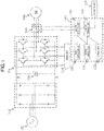
- FIG. 1 is an example of a configuration diagram of the power converter in Embodiments 1, 2, and 3.
- the configuration diagram in which a three-phase AC power source 101 and an AC electric motor 105 are connected to the power converter of this embodiment is illustrated.
- the power converter has a DC conversion unit 102, a smoothing capacitor 103, the AC conversion unit 104, a current detector 106, a control calculation unit 107, a current detection unit 108, an output control unit 110, a braking command unit 109, an output generation unit 111, a storage unit 112, an operation unit 113, and a driving unit 114.
- the three-phase AC power source 101 is, for example, three-phase AC voltage supplied from an electric power company or AC voltage supplied from a power generator and is output to the DC conversion unit 102.
- the DC conversion unit 102 includes, for example, a DC conversion circuit including diodes or a DC conversion circuit using an IGBT and a flywheel diode.
- the DC conversion unit 102 converts the AC voltage input from the three-phase AC power source 101 into DC voltage and outputs the DC voltage to the smoothing capacitor 103.
- DC conversion unit including diodes is illustrated in FIG. 1 .
- the smoothing capacitor 103 smoothes the DC voltage input from the DC conversion 102 and outputs the DC voltage to the AC conversion unit 104. For example, when the output from the electric motor is DC voltage, the DC voltage can be input to the smoothing capacitor 103 directly from the electric motor not via the DC conversion unit 106.
- the AC conversion unit 104 includes, for example, an AC conversion circuit using an IGBT and a flywheel diode and the DC voltage of the smoothing capacitor 103 is input to the AC conversion unit 104.
- the AC conversion unit 104 uses a PWM output waveform input from the driving unit 114, converts the DC voltage into the AC voltage using the PWM, and outputs the AC voltage to the AC electric motor 105.
- the PWM output being output from the AC conversion unit 104 is input to the AC electric motor 105 and the AC electric motor 105 drives a load. Specifically, the case of a synchronous electric motor will be described in Embodiment 1.
- the current detector 106 includes, for example, a hall CT and a shunt resistor, detects current flowing between the AC conversion unit 104 and the AC electric motor 105, and outputs the detected result to the current detection unit 108.
- the control calculation unit 107 includes, for example, a microcomputer, an ASIC, and a memory.
- the current signal from the current detector 106 or the operation command from the operation unit 113 is input to the control calculation unit 107 and the control calculation unit 107 performs various calculations and outputs the calculation results to the operation unit 113 or the AC conversion unit 104.
- the current detection unit 108 converts the acquired AC current value of each phase into an effective current value as an effective value. Furthermore, the current detection unit 108 averages or filters the acquired AC current value of each phase and uses the value as the AC average current value, and then the current detection unit 108 converts the AC average current value into the average effective current value as an effective value. Then, the current detection unit 108 outputs the respective current data to the output control unit 110.
- the AC current value of each phase and the effective current value, the AC average current value of each phase, and the average effective current value from the current detection unit 108, and the braking command from the braking command unit 109 are input to the output control unit 110.
- the output control unit 110 calculates an output command or an AC braking command and outputs the command to the output generation unit 111.
- the output control unit 110 calculates an output phase command and an output voltage command as an output command from the output frequency command, the acquired current, and various electric motor constants.
- the output control unit 110 detects the number of rotation of the electric motor from the AC current phase of each phase input from the current detection unit 108 and the AC average current phase of each phase during AC braking and uses the number of rotation of the electric motor for determining the start and stop operations of AC braking.
- the stop command output from the operation unit 113, the AC current value of each phase, the effective current value, the AC average current value of each phase, and the average effective current value from the current detection unit 108, and the braking time stored in the storage unit 112 are input to the braking command unit 109.
- the braking command unit 109 calculates a braking command and outputs the braking command to the output control unit 110.
- the output command information output from the output control unit 110 is input to the output generation unit 111.
- the output generation unit 111 generates PWM output waveform data and outputs the data to the driving unit 114.
- the storage unit 112 includes, for example, a magnetic disk, an optical disk, a flash memory, or an EEPROM.
- Various data from the operation unit 113 is input to the storage unit 112 and the storage unit 112 stores the data.
- a data acquisition request from the output control unit 110 or the braking command unit 109 is input to the storage unit 112 and the storage unit 112 outputs the data corresponding to the acquisition request to each requestor.
- the operation unit 113 has, for example, an output terminal portion sending a signal to the outside.
- the braking command information from the braking command unit 109 is input to the operation unit 113 and the operation unit 113 outputs a signal to an external device connected thereto.
- the operation unit 113 has, for example, an input terminal portion through which a signal is input from the outside. When a signal is input to the input terminal portion, the operation unit 113 outputs a braking command to the braking command unit 109.
- the PWM data output from the output generation unit 111 is input to the driving unit 114 and the driving unit 114 outputs a PWM output waveform to each element of the AC conversion unit 104.
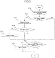
- FIG. 2 is a flowchart of the output control unit 110 for commanding AC braking in Embodiment 1.
- the output control unit 110 outputs a command for driving the synchronous electric motor connected thereto and monitors the braking command input from the braking command unit 109 at the same time (S201).
- the output control unit 110 determines whether the AC braking command is present or absent (S202). When there is no AC braking command allowance signal, the output control unit 110 continuously commands driving of the synchronous electric motor and, when there is an AC braking command allowance signal, the output control unit 110 outputs the AC braking command to the output generation unit 111 (S203).
- the output control unit 110 monitors failure in a power monitoring device, for example, failure in the current effective value detected by the current detection unit 108, by setting, for example, a current value necessary for protection in advance (S204). When there is no failure, the AC braking command is continuously performed and, when there is failure, the output control unit 110 turns off outputting and restarts AC braking (S205).
- a threshold value whether to restart is stored in the storage unit 112 in advance and whether to restart may be determined by reading the data at the time of restarting.
- the output control unit 110 calculates the number of rotation of the electric motor from the AC average current phase of each phase input from the current detection unit and determines whether the calculated rotation frequency is less than the frequency, for example, a value set as a start frequency of the power converter, at which it can be determined as stop in advance or a fixed value of rotation as low as 0.1 Hz (S206).
- the output control unit 110 determines that the rotation of the electric motor is stopped and finishes AC braking (S207).
- the power converter may be restarted or stopped after AC braking is finished.
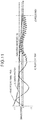
- FIG. 3 is an example of a view illustrating the relationship between a braking force and braking current in AC braking of Embodiment 1.
- FIG. 3 illustrates an example of the current which flows at the time of braking when AC single axis voltage is applied at the frequency higher than the rotation frequency of the shaft of the synchronous electric motor.
- the braking current includes the current (illustrated by the broken line) flowing by the induced voltage generated by the rotation of the synchronous electric motor and the current (illustrated by the dotted line) flowing by the AC voltage output of the power converter and the synthetic current(illustrated by the solid line) actually flows to the AC conversion unit.
- FIG. 3
- the current (illustrated by the broken line) flowing by the induced voltage generated by the rotation of the synchronous electric motor flows according to the relationship between the direction of the magnetic field emitted by the magnet of the synchronous electric motor and the rotation direction of the magnet depending on the general Fleming's left hand rule.
- the braking force by the rotation of the magnet is applied to be opposite to the rotation direction of the magnet from the directions of the flowing current and the magnetic field emitted by the magnet depending on the Fleming's left hand rule. Since the AC voltage is applied at the frequency higher than the rotation frequency of the synchronous electric motor, the current (illustrated by the dotted line) flowing by the AC voltage output of the power converter becomes AC current.
- the maximum frequency driving the synchronous electric motor is stored in the storage unit 112 and the cycle of five times mechanical constant calculated from, for example, an inertial load or the frequency of five times of the maximum frequency is set to the frequency of the single-axis AC voltage output, in such a manner that the output control unit 110 applies AC voltage without generation of a rotation force which can lead the synchronous electric motor to failure.
- the frequency of the applied AC voltage may be based on the present frequency of the synchronous electric motor and is set to any frequency as long as the synchronous electric motor steps out and the rotation cannot be continued.
- the forces applied to the synchronous electric motor are instantaneously offset by, for example, the pair of (A) and (E) or (B) and (D) in FIG. 3 and only the braking force by the rotation of the motor shaft remains.
- the synthetic current of the braking current corresponds to the AC current of each phase and only the braking current by the rotation of the motor shaft, that is, the AC average current, can be detected by using averaging or low-pass filtering.
- the number of rotation of the electric motor can be detected from the cycle of the AC average current which is the braking current by the rotation of the motor shaft. In this way, the power converter performs braking of synchronous electric motor.
- FIG. 4 is a view illustrating an example of the braking force and a current flow path when short-circuit braking is applied.
- FIG. 4 illustrates a state in which, when the voltage level is less than a predetermined voltage level when the number of rotation of the synchronous electric motor is reduced, the braking force is reduced.
- the elements of the AC conversion unit 104 are subjected to switching so that the potential becomes the same as that of the N line of, for example, the smoothing capacitor 103, and thus the current flows in short-circuit braking according to the voltage generated by the synchronous electric motor.
- the voltage generated by the synchronous electric motor is less than the voltage drop determined by each element by the voltage drop of each element, such as an IGBT or a diode, of the AC conversion unit 104, the current is prevented from flowing, and thus the braking force disappears.
- the inertial load is large, the synchronous electric motor continuously rotates by the inertia.
- AC braking is performed to avoid reduction in the braking force by the voltage drop.
- FIG. 5 is a view illustrating an example of the braking force and the current flow path when AC braking is applied.
- FIG. 5 illustrates a state in which, even when the voltage level is less than a predetermined voltage level when the number of rotation of the synchronous electric motor is reduced, the braking force follows the number of rotation of the synchronous electric motor. Since the DC voltage stored in the smoothing capacitor 103 instantaneously flows in AC braking, as illustrated in the lower side of FIG. 5 , the extent of the influence of the voltage drop in each element, such as an IGBT or a diode, of the AC conversion unit 104 is reduced, and thus current continuously flows and the braking force can be ensured.
- the power converter of this embodiment provides a mechanism in which the braking force is applied only in a stopping direction until the power converter stops, in such a manner that the power converter can be stopped in such a method described above even when the inertial load is large.
- Embodiment 1 a modification example of Embodiment 1 will be described.
- the same reference numerals and characters are given to parts which are used in common in Embodiment 1 and the detail of parts different from those of Embodiment 1 will be described.
- Embodiment 2 the configuration of the intermediate transfer belt 1 of Embodiment 1 is used.
- FIG. 6 is a flowchart relating to control switching of a braking command unit in Embodiment 2.
- the braking command unit 109 monitors the average effective current value input from the current detection unit 108 (S601) and determines whether the average effective current value is equal to or less than the predetermined AC braking threshold (S602).
- the AC braking threshold is set from, for example, the resistance value and inductance of the synchronous electric motor and the voltage obtained by subtracting the voltage drop of the elements of the AC conversion unit 104 from the induced voltage generated by the rotation so that current of equal to or more than, for example, 10% of the rated current of the 10 synchronous electric motor flows as output.
- the voltage of equal to or more than the voltage drop is instantaneously applied to each element by applying the AC voltage of the high frequency even when the number of rotation of the synchronous electric motor is reduced and the induced voltage is reduced, and thus current continuously flows.
- the AC current by applying AC voltage also includes the 15 braking current by rotation, and thus the braking force can be maintained.
- FIG. 7 illustrates a state in which AC braking is started by the AC braking threshold.
- AC current flowing to a U phase of the synchronous electric motor is illustrated as an example of the braking current.
- the current effective value calculated from three-phase AC current is illustrated.
- MATH. 1 shows the conversion of U-phase current (Iu) and W-phase current (Iw) 25 of three-phase AC current into a current value (I ⁇ ) in a U-phase direction and a current value (I ⁇ ) in an axial direction perpendicular to the U phase.
- I output I ⁇ 2 + I ⁇ 2
- MATH. 2 calculates the amount of effective current (Ioutput) from the current in the two-axis directions calculated in MATH. 1.
- Average effective current can be calculated in the same way as calculating the effective current by replacing the AC current (MATH. 1) (MATH. 2) with AC average current.
- the amount of the AC voltage applied during AC braking is controlled so that the amount of the effective current maintains a constant value in accordance with reduction in the number of rotation of the synchronous electric motor so that the amount of the braking current is prevented from becoming extremely small.
- the power converter of this embodiment provides a mechanism in which, even when an inertial load is large, the power converter can be stopped in such a method described above by applying the braking force only in the stopping direction until the power converter stops.
- Embodiment 2 A modification example of Embodiment 2 will be described in this embodiment.
- the same reference numerals and characters are given to parts which are used in common in Embodiment 1 and the detail of parts different from those of Embodiment 1 will be described.
- Embodiment 3 The configuration of the configuration diagram 1 of Embodiment 1 is used in Embodiment 3.
- FIG. 8 is a flowchart relating to a finish determination of the output control unit 110 by a time.
- Embodiment 3 is an example in which parts of finish determination (S207) (S208) of FIG. 2 illustrated in Embodiment 1 are replaced with parts of (S801) to (S803) illustrated in FIG. 8 .
- the output control unit 110 updates the braking time of AC braking when AC braking is started (S801).
- the output control unit 110 compares a braking stop time which is stored in the storage unit 112 in advance and the undated braking time (S802). When the updated braking time is within the period of the braking stop time, braking is continued and, when the updated braking time is out of the braking stop time, AC braking is finished (S803).
- the power converter may be restarted or stopped after AC braking is finished. Setting the braking stop time is effective when braking is necessary even after the AC electric motor is stopped.
- FIG. 9 is an example of a view illustrating the relationship between the state of braking and a time.
- AC current and effective current flowing to the U phase of the synchronous electric motor are illustrated as an example of braking current.
- FIG. 9 a state in which the output is cut off after a predetermined time elapses from the start of AC braking as illustrated in FIG. 8 .
- a braking time of completely stopping the power converter by AC braking is set in advance.
- the power converter of this embodiment provides a mechanism in which the braking force is applied only in a stopping direction until the power converter stops, in such a manner that the power converter can be stopped with monitoring a time in such a method described above even when the inertial load is large.
- Embodiment 2 A modification example of Embodiment 2 is illustrated in this embodiment.
- the same reference numerals and characters are given to parts which are used in common in Embodiment 1 and the detail of parts different from those of Embodiment 1 will be described.
- Embodiment 4 The configuration of the configuration diagram 1 of Embodiment 1 is used in Embodiment 4.
- FIG. 10 is a flowchart relating to a finish determination of the output control unit 110 by an average current.
- Embodiment 3 is an example in which parts of finish determination (S207) (S208) of FIG. 2 illustrated in Embodiment 1 are replaced with parts of (S1001) to (S1003) illustrated in FIG. 8 .
- the output control unit 110 acquires the average effective current when AC braking is started (S1001).
- the output control unit 110 compares a specific value of stop determination current which is stored in the storage unit 112 in advance and the acquired average effective current value (S1002). When the acquired average effective current value is equal to or greater than the specific value, braking is continued and, when the acquired average effective current value is equal to or less than the specific value, AC braking is finished (S803).
- the power converter may be restarted or stopped after AC braking is finished. Setting the stop determination current can reduce the wear of component elements of the AC conversion unit 104 because the stop of the power converter can be determined using the value of the average effective current flowing by the rotation, and thus AC voltage is prevented from being applied for an unnecessarily long time.
- FIG. 11 is an example of a view illustrating the relationship between the state of braking and the time.
- current flowing to a U phase of the synchronous electric motor and the average effective current value are illustrated as an example of the braking current.
- FIG. 11 a state in which the output is cut off when the average effective current value is smaller than a finish determination threshold after AC braking is started as illustrated in FIG. 10 is illustrated.
- a current value where it is considered that the synchronous electric motor is stopped is set in advance.
- the power converter of this embodiment provides a mechanism in which, even when an inertial load is large, the power converter can be stopped with monitoring output current in such a method described above by applying the braking force only in the stopping direction until the power converter stops.
- the power converter includes an AC conversion unit which converts DC power into predetermined AC power, a current detector which detects current flowing in the AC conversion unit, and a control unit which controls output of the AC conversion unit and the power converter is characterized in that the control unit performs AC braking so that braking is performed by allowing AC current of a condition not applying a rotation force to an AC electric motor to flow in a deceleration mode of the AC electric motor connected to the power converter.
- the power converter is characterized in that AC braking by the control unit is performed by applying AC voltage of a frequency higher than the rotation frequency of the AC electric motor.
- the power converter is characterized in that the application of AC voltage in the control unit is performed by fixing a phase in a certain axis direction and applying AC voltage in one axis direction.
- the power converter is characterized in that the control unit performs AC voltage control on the basis of the comparison of an output current value obtained by converting current detected by the current detector and a predetermined value set in advance.
- the power converter is characterized in that the control unit performs AC voltage control on the basis of a predetermined voltage value decided in association with elements of the AC conversion unit.
- the power converter is characterized in that the control unit performs short-circuit braking so that braking is applied by short-circuiting three phases and performs AC braking when a speed is equal to or less than a predetermined speed.
- the power converter is characterized in that the control unit performs AC braking for a predetermined time set in advance and finishes braking.
- the power converter is characterized in that the control unit finishes a braking operation on the basis of an AC average current value set in advance.
- each of above-described configurations functions, processing units, processing means, and the likes, part or all thereof may be realized by hardware by, for example, designing them with an integrated circuit pr the like.
- each of the above-described configurations, functions, and the likes may be realized by software by interpreting and executing a program with which the processor realizes each function.
- Information on such as a program, a table, and a file for realizing each function can be stored in a recording device such as a memory, a hard disk, and a Solid State Drive (SSD) or a recording medium such as an IC card, an SD card, and a DVD.
- SSD Solid State Drive
- control line and an information line indicate what is considered to be necessary for the explanation and are not intended to be limited to necessarily indicate the entirety of the control line and the information line of a product. In practice, it can be considered that almost all the configurations are connected to one another.
Landscapes
- Engineering & Computer Science (AREA)
- Power Engineering (AREA)
- Stopping Of Electric Motors (AREA)
- Control Of Ac Motors In General (AREA)
Claims (13)
- Convertisseur de puissance comprenant :une unité de conversion CA (104) conçue pour convertir une puissance CC en une puissance CA prédéterminée ;un détecteur de courant (106) conçu pour détecter le courant circulant vers l'unité de conversion CA ; etune unité de commande (110) conçue pour commander la sortie de l'unité de conversion CA,dans lequel l'unité de commande est conçue pour effectuer un freinage à courant alternatif d'un moteur électrique synchrone (105) connecté au convertisseur de puissance par application d'une tension alternative d'une fréquence supérieure à la fréquence de rotation du moteur électrique synchrone dans un mode de décélération au moteur électrique synchrone sans générer de force de rotation sur le moteur électrique synchrone.
- Convertisseur de puissance selon la revendication 1, dans lequel l'unité de commande (110) est conçue pour effectuer l'application d'une tension alternative en fixant une phase dans une direction d'axe optionnelle et en appliquant une tension alternative dans une direction d'axe.
- Convertisseur de puissance selon la revendication 1, dans lequel l'unité de commande (110) est conçue pour effectuer une commande de tension alternative sur la base de la comparaison d'une valeur de courant de sortie obtenue par conversion d'un courant détecté par le détecteur de courant (106) et d'une valeur prédéterminée définie à l'avance.
- Convertisseur de puissance selon la revendication 1, dans lequel l'unité de commande (110) est conçue pour effectuer une commande de tension alternative sur la base d'une valeur de tension prédéterminée déterminée en association avec des éléments de l'unité de conversion CA (104).
- Convertisseur de puissance selon la revendication 1, dans lequel l'unité de commande (110) est conçue pour effectuer un freinage par court-circuit de sorte que le freinage soit appliqué en court-circuitant trois phases et pour effectuer un freinage à courant alternatif lorsqu'une vitesse est inférieure ou égale à une vitesse prédéterminée.
- Convertisseur de puissance selon la revendication 1, dans lequel l'unité de commande (110) est conçue pour effectuer un freinage à courant alternatif pendant une durée prédéterminée fixée à l'avance et pour terminer le freinage.
- Convertisseur de puissance selon la revendication 1, dans lequel l'unité de commande (110) est conçue pour terminer une opération de freinage sur la base d'une valeur de courant alternatif moyenne réglée à l'avance.
- Procédé de commande d'un convertisseur de puissance, comprenant :un processus de conversion CA pour convertir une puissance CC en une puissance CA prédéterminée ;un processus de détection de courant pour détecter un courant qui est converti pour circuler par le processus de conversion CA ; etun processus de commande pour commander la sortie vers le processus de conversion CA,dans lequel le processus de commande effectue un freinage à courant alternatif d'un moteur électrique synchrone connecté au convertisseur de puissance par application d'une tension alternative d'une fréquence supérieure à la fréquence de rotation du moteur électrique synchrone dans un mode de décélération au moteur électrique synchrone sans générer de force de rotation sur le moteur électrique synchrone.
- Procédé de commande du convertisseur de puissance selon la revendication 8,
dans lequel l'application d'une tension alternative dans le processus de commande est effectuée en fixant une phase dans une direction d'axe optionnelle et en appliquant une tension alternative dans une direction d'axe. - Procédé de commande du convertisseur de puissance selon la revendication 8,
dans lequel le processus de commande effectue une commande de tension alternative sur la base de la comparaison d'une valeur de courant de sortie obtenue par conversion du courant détecté dans le processus de détection de courant et d'une valeur prédéterminée définie à l'avance. - Procédé de commande du convertisseur de puissance selon la revendication 8,
dans lequel le processus de commande effectue une commande de tension alternative sur la base d'une valeur de tension prédéterminée déterminée en association avec des éléments de l'unité de conversion CA. - Procédé de commande du convertisseur de puissance selon la revendication 8,
dans lequel le processus de commande effectue un freinage par court-circuit de sorte que le freinage est appliqué en court-circuitant trois phases, et effectue un freinage à courant alternatif lorsqu'une vitesse est inférieure ou égale à une vitesse prédéterminée. - Procédé de commande du convertisseur de puissance selon la revendication 8,
dans lequel le processus de commande effectue un freinage à courant alternatif pendant une durée prédéterminée définie à l'avance et termine le freinage.
Applications Claiming Priority (1)
| Application Number | Priority Date | Filing Date | Title |
|---|---|---|---|
| PCT/JP2014/079519 WO2016072003A1 (fr) | 2014-11-07 | 2014-11-07 | Convertisseur de puissance et procédé de commande de convertisseur de puissance |
Publications (3)
| Publication Number | Publication Date |
|---|---|
| EP3229367A1 EP3229367A1 (fr) | 2017-10-11 |
| EP3229367A4 EP3229367A4 (fr) | 2018-07-11 |
| EP3229367B1 true EP3229367B1 (fr) | 2020-10-07 |
Family
ID=55908755
Family Applications (1)
| Application Number | Title | Priority Date | Filing Date |
|---|---|---|---|
| EP14905548.5A Active EP3229367B1 (fr) | 2014-11-07 | 2014-11-07 | Convertisseur de puissance et procédé de commande de convertisseur de puissance |
Country Status (4)
| Country | Link |
|---|---|
| EP (1) | EP3229367B1 (fr) |
| JP (1) | JP6353925B2 (fr) |
| CN (1) | CN107078679B (fr) |
| WO (1) | WO2016072003A1 (fr) |
Families Citing this family (2)
| Publication number | Priority date | Publication date | Assignee | Title |
|---|---|---|---|---|
| GB2565059A (en) * | 2017-07-28 | 2019-02-06 | Edwards Ltd | Induction motor control |
| CN107317527B (zh) * | 2017-08-11 | 2019-05-03 | 常州机电职业技术学院 | 无刷直流电机、无刷直流电机制动控制方法及装置 |
Family Cites Families (8)
| Publication number | Priority date | Publication date | Assignee | Title |
|---|---|---|---|---|
| JPS59117477A (ja) * | 1982-12-24 | 1984-07-06 | Toshiba Corp | 電動機の制御装置 |
| JPH0647040B2 (ja) * | 1986-05-09 | 1994-06-22 | 株式会社東芝 | 脱水用モ−タの制動装置 |
| US6262555B1 (en) * | 1998-10-02 | 2001-07-17 | Robicon Corporation | Apparatus and method to generate braking torque in an AC drive |
| US6831432B2 (en) * | 2001-12-05 | 2004-12-14 | Matsushita Electric Industrial Co., Ltd. | Motor driving device and motor driving method |
| JP5168536B2 (ja) * | 2007-03-06 | 2013-03-21 | 株式会社ジェイテクト | モータ制御装置 |
| JP5372705B2 (ja) * | 2009-11-04 | 2013-12-18 | 株式会社日立産機システム | 電力変換装置 |
| JP5545359B2 (ja) * | 2010-07-22 | 2014-07-09 | トヨタ自動車株式会社 | 車両制御システム |
| JP5804984B2 (ja) * | 2012-03-07 | 2015-11-04 | 株式会社ツバキE&M | モータ駆動装置 |
-
2014
- 2014-11-07 CN CN201480081055.8A patent/CN107078679B/zh active Active
- 2014-11-07 JP JP2016557412A patent/JP6353925B2/ja active Active
- 2014-11-07 WO PCT/JP2014/079519 patent/WO2016072003A1/fr active Application Filing
- 2014-11-07 EP EP14905548.5A patent/EP3229367B1/fr active Active
Non-Patent Citations (1)
| Title |
|---|
| None * |
Also Published As
| Publication number | Publication date |
|---|---|
| JPWO2016072003A1 (ja) | 2017-06-29 |
| JP6353925B2 (ja) | 2018-07-04 |
| CN107078679A (zh) | 2017-08-18 |
| WO2016072003A1 (fr) | 2016-05-12 |
| EP3229367A1 (fr) | 2017-10-11 |
| EP3229367A4 (fr) | 2018-07-11 |
| CN107078679B (zh) | 2020-03-31 |
Similar Documents
| Publication | Publication Date | Title |
|---|---|---|
| JP6277288B2 (ja) | 監視装置と監視方法およびそれらを備える制御装置と制御方法 | |
| US10158318B2 (en) | Control device for in-vehicle electric motor | |
| JP5954313B2 (ja) | モータ制御システム、制御装置及び制御方法 | |
| JP2013115994A (ja) | 停電の有無を判定する停電判定部を有するモータ駆動装置 | |
| TW201424246A (zh) | 馬達控制裝置 | |
| JP6286450B2 (ja) | 電力変換装置 | |
| JP6420405B1 (ja) | 異常診断装置および異常診断方法 | |
| JP6282338B2 (ja) | 電力変換装置及び電力変換方法 | |
| CN111656669B (zh) | 控制装置 | |
| EP3229367B1 (fr) | Convertisseur de puissance et procédé de commande de convertisseur de puissance | |
| JP6420381B2 (ja) | モータ駆動装置 | |
| CN113454902A (zh) | 马达驱动装置以及空调机 | |
| JP7205176B2 (ja) | モータ駆動システム | |
| JP6304401B2 (ja) | 電動機の制御装置及び制御方法 | |
| US11296625B2 (en) | Control device and control method for synchronous electric motor | |
| JP5631200B2 (ja) | 同期電動機の制御装置、及び同期発電機の制御装置 | |
| JP2014143839A (ja) | 電動機の制御装置 | |
| JP2009148065A (ja) | 電動機制御装置及びこれを搭載した空気調和機 | |
| KR101620853B1 (ko) | 유도전동기 구동 제어 장치 | |
| JP6520111B2 (ja) | ロック検出装置 | |
| JP4265395B2 (ja) | インバータ装置 | |
| KR20140141502A (ko) | 모터 제어 장치 및 그것을 구비한 건설 기계 | |
| WO2017085820A1 (fr) | Dispositif de conversion de puissance | |
| JP2012178900A (ja) | 電力変換装置 |
Legal Events
| Date | Code | Title | Description |
|---|---|---|---|
| STAA | Information on the status of an ep patent application or granted ep patent |
Free format text: STATUS: THE INTERNATIONAL PUBLICATION HAS BEEN MADE |
|
| PUAI | Public reference made under article 153(3) epc to a published international application that has entered the european phase |
Free format text: ORIGINAL CODE: 0009012 |
|
| STAA | Information on the status of an ep patent application or granted ep patent |
Free format text: STATUS: REQUEST FOR EXAMINATION WAS MADE |
|
| PUAB | Information related to the publication of an a document modified or deleted |
Free format text: ORIGINAL CODE: 0009199EPPU |
|
| PUAI | Public reference made under article 153(3) epc to a published international application that has entered the european phase |
Free format text: ORIGINAL CODE: 0009012 |
|
| 17P | Request for examination filed |
Effective date: 20170606 |
|
| AK | Designated contracting states |
Kind code of ref document: A1 Designated state(s): AL AT BE BG CH CY CZ DE DK EE ES FI FR GB GR HR HU IE IS IT LI LT LU LV MC MK MT NL NO PL PT RO RS SE SI SK SM TR |
|
| AX | Request for extension of the european patent |
Extension state: BA ME |
|
| DAX | Request for extension of the european patent (deleted) | ||
| A4 | Supplementary search report drawn up and despatched |
Effective date: 20180607 |
|
| RIC1 | Information provided on ipc code assigned before grant |
Ipc: H02P 27/06 20060101AFI20180601BHEP Ipc: H02P 3/18 20060101ALI20180601BHEP |
|
| GRAP | Despatch of communication of intention to grant a patent |
Free format text: ORIGINAL CODE: EPIDOSNIGR1 |
|
| STAA | Information on the status of an ep patent application or granted ep patent |
Free format text: STATUS: GRANT OF PATENT IS INTENDED |
|
| INTG | Intention to grant announced |
Effective date: 20200525 |
|
| GRAS | Grant fee paid |
Free format text: ORIGINAL CODE: EPIDOSNIGR3 |
|
| GRAA | (expected) grant |
Free format text: ORIGINAL CODE: 0009210 |
|
| STAA | Information on the status of an ep patent application or granted ep patent |
Free format text: STATUS: THE PATENT HAS BEEN GRANTED |
|
| AK | Designated contracting states |
Kind code of ref document: B1 Designated state(s): AL AT BE BG CH CY CZ DE DK EE ES FI FR GB GR HR HU IE IS IT LI LT LU LV MC MK MT NL NO PL PT RO RS SE SI SK SM TR |
|
| REG | Reference to a national code |
Ref country code: GB Ref legal event code: FG4D |
|
| REG | Reference to a national code |
Ref country code: AT Ref legal event code: REF Ref document number: 1322239 Country of ref document: AT Kind code of ref document: T Effective date: 20201015 Ref country code: CH Ref legal event code: EP |
|
| REG | Reference to a national code |
Ref country code: IE Ref legal event code: FG4D |
|
| REG | Reference to a national code |
Ref country code: DE Ref legal event code: R096 Ref document number: 602014071132 Country of ref document: DE |
|
| REG | Reference to a national code |
Ref country code: NL Ref legal event code: MP Effective date: 20201007 |
|
| REG | Reference to a national code |
Ref country code: AT Ref legal event code: MK05 Ref document number: 1322239 Country of ref document: AT Kind code of ref document: T Effective date: 20201007 |
|
| PG25 | Lapsed in a contracting state [announced via postgrant information from national office to epo] |
Ref country code: FI Free format text: LAPSE BECAUSE OF FAILURE TO SUBMIT A TRANSLATION OF THE DESCRIPTION OR TO PAY THE FEE WITHIN THE PRESCRIBED TIME-LIMIT Effective date: 20201007 Ref country code: RS Free format text: LAPSE BECAUSE OF FAILURE TO SUBMIT A TRANSLATION OF THE DESCRIPTION OR TO PAY THE FEE WITHIN THE PRESCRIBED TIME-LIMIT Effective date: 20201007 Ref country code: NL Free format text: LAPSE BECAUSE OF FAILURE TO SUBMIT A TRANSLATION OF THE DESCRIPTION OR TO PAY THE FEE WITHIN THE PRESCRIBED TIME-LIMIT Effective date: 20201007 Ref country code: NO Free format text: LAPSE BECAUSE OF FAILURE TO SUBMIT A TRANSLATION OF THE DESCRIPTION OR TO PAY THE FEE WITHIN THE PRESCRIBED TIME-LIMIT Effective date: 20210107 Ref country code: PT Free format text: LAPSE BECAUSE OF FAILURE TO SUBMIT A TRANSLATION OF THE DESCRIPTION OR TO PAY THE FEE WITHIN THE PRESCRIBED TIME-LIMIT Effective date: 20210208 Ref country code: GR Free format text: LAPSE BECAUSE OF FAILURE TO SUBMIT A TRANSLATION OF THE DESCRIPTION OR TO PAY THE FEE WITHIN THE PRESCRIBED TIME-LIMIT Effective date: 20210108 |
|
| REG | Reference to a national code |
Ref country code: LT Ref legal event code: MG4D |
|
| PG25 | Lapsed in a contracting state [announced via postgrant information from national office to epo] |
Ref country code: IS Free format text: LAPSE BECAUSE OF FAILURE TO SUBMIT A TRANSLATION OF THE DESCRIPTION OR TO PAY THE FEE WITHIN THE PRESCRIBED TIME-LIMIT Effective date: 20210207 Ref country code: PL Free format text: LAPSE BECAUSE OF FAILURE TO SUBMIT A TRANSLATION OF THE DESCRIPTION OR TO PAY THE FEE WITHIN THE PRESCRIBED TIME-LIMIT Effective date: 20201007 Ref country code: LV Free format text: LAPSE BECAUSE OF FAILURE TO SUBMIT A TRANSLATION OF THE DESCRIPTION OR TO PAY THE FEE WITHIN THE PRESCRIBED TIME-LIMIT Effective date: 20201007 Ref country code: SE Free format text: LAPSE BECAUSE OF FAILURE TO SUBMIT A TRANSLATION OF THE DESCRIPTION OR TO PAY THE FEE WITHIN THE PRESCRIBED TIME-LIMIT Effective date: 20201007 Ref country code: BG Free format text: LAPSE BECAUSE OF FAILURE TO SUBMIT A TRANSLATION OF THE DESCRIPTION OR TO PAY THE FEE WITHIN THE PRESCRIBED TIME-LIMIT Effective date: 20210107 Ref country code: AT Free format text: LAPSE BECAUSE OF FAILURE TO SUBMIT A TRANSLATION OF THE DESCRIPTION OR TO PAY THE FEE WITHIN THE PRESCRIBED TIME-LIMIT Effective date: 20201007 Ref country code: ES Free format text: LAPSE BECAUSE OF FAILURE TO SUBMIT A TRANSLATION OF THE DESCRIPTION OR TO PAY THE FEE WITHIN THE PRESCRIBED TIME-LIMIT Effective date: 20201007 |
|
| PG25 | Lapsed in a contracting state [announced via postgrant information from national office to epo] |
Ref country code: HR Free format text: LAPSE BECAUSE OF FAILURE TO SUBMIT A TRANSLATION OF THE DESCRIPTION OR TO PAY THE FEE WITHIN THE PRESCRIBED TIME-LIMIT Effective date: 20201007 |
|
| REG | Reference to a national code |
Ref country code: CH Ref legal event code: PL |
|
| REG | Reference to a national code |
Ref country code: DE Ref legal event code: R097 Ref document number: 602014071132 Country of ref document: DE |
|
| PG25 | Lapsed in a contracting state [announced via postgrant information from national office to epo] |
Ref country code: SK Free format text: LAPSE BECAUSE OF FAILURE TO SUBMIT A TRANSLATION OF THE DESCRIPTION OR TO PAY THE FEE WITHIN THE PRESCRIBED TIME-LIMIT Effective date: 20201007 Ref country code: RO Free format text: LAPSE BECAUSE OF FAILURE TO SUBMIT A TRANSLATION OF THE DESCRIPTION OR TO PAY THE FEE WITHIN THE PRESCRIBED TIME-LIMIT Effective date: 20201007 Ref country code: LU Free format text: LAPSE BECAUSE OF NON-PAYMENT OF DUE FEES Effective date: 20201107 Ref country code: LT Free format text: LAPSE BECAUSE OF FAILURE TO SUBMIT A TRANSLATION OF THE DESCRIPTION OR TO PAY THE FEE WITHIN THE PRESCRIBED TIME-LIMIT Effective date: 20201007 Ref country code: MC Free format text: LAPSE BECAUSE OF FAILURE TO SUBMIT A TRANSLATION OF THE DESCRIPTION OR TO PAY THE FEE WITHIN THE PRESCRIBED TIME-LIMIT Effective date: 20201007 Ref country code: SM Free format text: LAPSE BECAUSE OF FAILURE TO SUBMIT A TRANSLATION OF THE DESCRIPTION OR TO PAY THE FEE WITHIN THE PRESCRIBED TIME-LIMIT Effective date: 20201007 Ref country code: CZ Free format text: LAPSE BECAUSE OF FAILURE TO SUBMIT A TRANSLATION OF THE DESCRIPTION OR TO PAY THE FEE WITHIN THE PRESCRIBED TIME-LIMIT Effective date: 20201007 Ref country code: EE Free format text: LAPSE BECAUSE OF FAILURE TO SUBMIT A TRANSLATION OF THE DESCRIPTION OR TO PAY THE FEE WITHIN THE PRESCRIBED TIME-LIMIT Effective date: 20201007 |
|
| REG | Reference to a national code |
Ref country code: BE Ref legal event code: MM Effective date: 20201130 |
|
| PLBE | No opposition filed within time limit |
Free format text: ORIGINAL CODE: 0009261 |
|
| STAA | Information on the status of an ep patent application or granted ep patent |
Free format text: STATUS: NO OPPOSITION FILED WITHIN TIME LIMIT |
|
| PG25 | Lapsed in a contracting state [announced via postgrant information from national office to epo] |
Ref country code: LI Free format text: LAPSE BECAUSE OF NON-PAYMENT OF DUE FEES Effective date: 20201130 Ref country code: DK Free format text: LAPSE BECAUSE OF FAILURE TO SUBMIT A TRANSLATION OF THE DESCRIPTION OR TO PAY THE FEE WITHIN THE PRESCRIBED TIME-LIMIT Effective date: 20201007 Ref country code: CH Free format text: LAPSE BECAUSE OF NON-PAYMENT OF DUE FEES Effective date: 20201130 |
|
| 26N | No opposition filed |
Effective date: 20210708 |
|
| GBPC | Gb: european patent ceased through non-payment of renewal fee |
Effective date: 20210107 |
|
| PG25 | Lapsed in a contracting state [announced via postgrant information from national office to epo] |
Ref country code: IE Free format text: LAPSE BECAUSE OF NON-PAYMENT OF DUE FEES Effective date: 20201107 Ref country code: AL Free format text: LAPSE BECAUSE OF FAILURE TO SUBMIT A TRANSLATION OF THE DESCRIPTION OR TO PAY THE FEE WITHIN THE PRESCRIBED TIME-LIMIT Effective date: 20201007 |
|
| PG25 | Lapsed in a contracting state [announced via postgrant information from national office to epo] |
Ref country code: GB Free format text: LAPSE BECAUSE OF NON-PAYMENT OF DUE FEES Effective date: 20210107 Ref country code: SI Free format text: LAPSE BECAUSE OF FAILURE TO SUBMIT A TRANSLATION OF THE DESCRIPTION OR TO PAY THE FEE WITHIN THE PRESCRIBED TIME-LIMIT Effective date: 20201007 |
|
| PG25 | Lapsed in a contracting state [announced via postgrant information from national office to epo] |
Ref country code: IS Free format text: LAPSE BECAUSE OF FAILURE TO SUBMIT A TRANSLATION OF THE DESCRIPTION OR TO PAY THE FEE WITHIN THE PRESCRIBED TIME-LIMIT Effective date: 20210207 Ref country code: TR Free format text: LAPSE BECAUSE OF FAILURE TO SUBMIT A TRANSLATION OF THE DESCRIPTION OR TO PAY THE FEE WITHIN THE PRESCRIBED TIME-LIMIT Effective date: 20201007 Ref country code: MT Free format text: LAPSE BECAUSE OF FAILURE TO SUBMIT A TRANSLATION OF THE DESCRIPTION OR TO PAY THE FEE WITHIN THE PRESCRIBED TIME-LIMIT Effective date: 20201007 Ref country code: CY Free format text: LAPSE BECAUSE OF FAILURE TO SUBMIT A TRANSLATION OF THE DESCRIPTION OR TO PAY THE FEE WITHIN THE PRESCRIBED TIME-LIMIT Effective date: 20201007 |
|
| PG25 | Lapsed in a contracting state [announced via postgrant information from national office to epo] |
Ref country code: MK Free format text: LAPSE BECAUSE OF FAILURE TO SUBMIT A TRANSLATION OF THE DESCRIPTION OR TO PAY THE FEE WITHIN THE PRESCRIBED TIME-LIMIT Effective date: 20201007 |
|
| PG25 | Lapsed in a contracting state [announced via postgrant information from national office to epo] |
Ref country code: BE Free format text: LAPSE BECAUSE OF NON-PAYMENT OF DUE FEES Effective date: 20201130 |
|
| PGFP | Annual fee paid to national office [announced via postgrant information from national office to epo] |
Ref country code: FR Payment date: 20230929 Year of fee payment: 10 |
|
| PGFP | Annual fee paid to national office [announced via postgrant information from national office to epo] |
Ref country code: IT Payment date: 20231010 Year of fee payment: 10 Ref country code: DE Payment date: 20230929 Year of fee payment: 10 |