EP3228765A1 - Leitungsstückanordnung - Google Patents
Leitungsstückanordnung Download PDFInfo
- Publication number
- EP3228765A1 EP3228765A1 EP16164230.1A EP16164230A EP3228765A1 EP 3228765 A1 EP3228765 A1 EP 3228765A1 EP 16164230 A EP16164230 A EP 16164230A EP 3228765 A1 EP3228765 A1 EP 3228765A1
- Authority
- EP
- European Patent Office
- Prior art keywords
- throttle
- closure element
- line piece
- line
- section
- Prior art date
- Legal status (The legal status is an assumption and is not a legal conclusion. Google has not performed a legal analysis and makes no representation as to the accuracy of the status listed.)
- Granted
Links
Images
Classifications
-
- E—FIXED CONSTRUCTIONS
- E03—WATER SUPPLY; SEWERAGE
- E03D—WATER-CLOSETS OR URINALS WITH FLUSHING DEVICES; FLUSHING VALVES THEREFOR
- E03D9/00—Sanitary or other accessories for lavatories ; Devices for cleaning or disinfecting the toilet room or the toilet bowl; Devices for eliminating smells
- E03D9/16—Water pressure regulating means in flushing pipes
-
- E—FIXED CONSTRUCTIONS
- E03—WATER SUPPLY; SEWERAGE
- E03B—INSTALLATIONS OR METHODS FOR OBTAINING, COLLECTING, OR DISTRIBUTING WATER
- E03B7/00—Water main or service pipe systems
- E03B7/07—Arrangement of devices, e.g. filters, flow controls, measuring devices, siphons or valves, in the pipe systems
- E03B7/075—Arrangement of devices for control of pressure or flow rate
Definitions
- a tubing assembly for a sanitary article comprises one extending along a central axis extending conduit piece with a wall and with an inlet and an outlet, and arranged in the line piece throttle element with which the cross section of the line piece can be changed. Water is supplied to the pipe section via the inlet. The outlet opens towards the sanitary article.
- the wall extends substantially completely around the central axis.
- the throttle element comprises at least one throttle web fixedly arranged in the line piece, wherein the at least one throttle web protrudes into the cross section of the line piece.
- the throttle element further comprises at least one closure element which can be arranged in contact with the at least one throttle web in the line section to increase the throttling.
- the at least one closure element extends over a circular sector surface, which circular sector surface is smaller than the cross section of the line piece.
- the at least one closure element comprises latching means with which the at least one closure element is clamped to the throttle bars.
- the closure element can be used particularly well in the intermediate space.
- the Locking means are preferably in the space a latching or clamping connection with the throttle bar.
- the at least one closure element extends substantially over a surface, in particular a circular surface.
- the area or circular area is smaller than the cross section of the pipe section.
- the closure element comprises in the center a bearing opening for mounting the closure element on the bearing rod. The closure element can then be pushed over the bearing rod.
- the oriented against the direction of flow surface of the closure element according to the second embodiment is oriented at right angles or at an angle inclined to the central axis.
- the closure element is frusto-conical.
- the first embodiment is combined with the second embodiment. Consequently, the throttle element comprises the at least one throttle web fixedly arranged in the line piece and the bearing rod protruding from the at least one throttle web in the direction of the central axis. At least one throttle web, the closure element according to the first embodiment and on the bearing rod, the closure element is mounted according to the second embodiment.
- the at least one throttle bar extends substantially from the middle of the line piece at right angles to the central axis of the line piece up to the wall of the line piece.
- a plurality of throttle webs are arranged at the same angular distance from each other, wherein the throttle webs are preferably arranged distributed uniformly over the entire cross section of the pipe section.
- the at least one throttle web is firmly formed on the pipe section.
- the at least one throttle web and the line piece are thus integrally connected to each other.
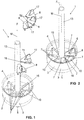
- a line piece assembly 1 is shown.
- the line piece arrangement 1 comprises a line piece 2 extending along a central axis M with a wall 3 and with an inlet 4 and an outlet 5.
- a throttle element 6, which likewise leads to the line piece arrangement 1, is arranged in the line piece 2. With the throttle element 6, the cross section of the pipe section 2 can be changed.
- the throttle element 6, which in the FIG. 1 is shown in an exploded perspective view and which in the FIG. 2 is shown in the mounted position, comprises at least one fixedly arranged in the line piece 2 choke web 7.
- eight fixed throttle web 7 are arranged.
- the at least one fixed throttle ridge 7 is fixed in the line piece 2.
- the at least one fixed throttle ridge 7 is integrally formed on the wall 3 of the line piece 2.
- the fixed throttle web 7 extends from the wall 3 in the direction of the interior of the pipe section 2 substantially up to the central axis M.
- the fixed throttle web 7 is oriented substantially perpendicular to the central axis M of the pipe section 2.
- the throttle element 6 comprises at least one closure element 8, 9 which can be arranged in contact with the at least one throttle web 7 in the line section 2 to increase the throttling.
- the closure element 8, 9 can be designed in various ways be and serves essentially to increase the cross-section of the throttle element 6 in its entirety.
- a first embodiment of the throttle element 8 is shown.
- a second embodiment of the throttle element 9 is shown.
- the two embodiments can also be combined with each other in a third embodiment.
- eight fixed throttle webs 7 are arranged, which are each at the same angular distance ⁇ to each other. It can also be arranged more or less throttle webs 7.
- the throttle webs 7 extend in the embodiment shown from a midpoint M radially to the central axis M to the wall 3.
- the angular spacing of the throttle webs 7 also defines the intermediate space 10 between the throttle webs 7, which is to be closed by the closure element 8. In this respect, it is preferred that the angle of the circular segment surface substantially corresponds to the angular distance ⁇ between two throttle webs 7.
- the closure element 8 in addition to or as an alternative to the latching means 11, has guide pins 18 which guide the closure element 8 with respect to the throttle ribs 7.
- the closure elements 8 are with respect to the flow direction F in front of the throttle bars. 7 arranged so that the closure elements 8 are pressed by the flowing through the line piece of water against the throttle web 7.
- the closure elements 8 shown are preferably connected to one another via a predetermined breaking point 12, as shown in FIG FIG. 1 is symbolized.
- the installer can then cancel the desired number of closure elements 8 at the predetermined breaking point 12 accordingly. After canceling the desired number, the installer can then use the closure elements 8 in the gap 10 between the two adjacent throttle webs 7.
- the closure element 8 comprises a tab 17.
- the tab 17 essentially serves as a grip tab, so that the closure element can be easily gripped by the installer.
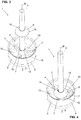
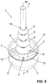
- FIGS. 3 to 5 a further embodiment of the closure element 9 is shown.
- the closure element 9 extends from the bearing eye 16 of the throttle webs 7, a bearing rod 13 in the direction of the central axis M away.
- the at least one closure element 9 is mounted.
- the closure element 9 has the outer shape of a circular area which is smaller than the cross section of the conduit section 2.
- the at least one closure element 9 comprises a bearing opening 14 centrally, which serves to mount the closure element 9 on the bearing bar 13. The closure element 9 can therefore be pushed along the bearing rod 13 as far as the throttle webs 7, where it rests on the throttle webs 7 accordingly.
- three fixed throttle webs 7 are present.
- the number of fixed throttle land 7 may also be greater or less than three.
- the surface 15 of the closure element 9 may be oriented at right angles to the central axis M. Alternatively, as shown in the figures, the surface 15 may be oriented angularly inclined with respect to the central axis M when viewed in cross-section, resulting in a kind of truncated cone. By forming the surface 15 of the throttle resistance can be influenced.
- FIGS. 3 and 4 a single closure element 9 is arranged.
- the throttle effect can be changed by the closure element 9 is used with different diameters. Consequently, it is advantageous if a plurality of closure elements 9 are present in a set and the installer then selects the closure element 9 with the desired diameter.
- closure elements 8 according to the Figures 1 and 2 and the closure elements 9 according to the FIGS. 3 to 5 used. It is a combined arrangement.
Landscapes
- Health & Medical Sciences (AREA)
- Public Health (AREA)
- Life Sciences & Earth Sciences (AREA)
- Engineering & Computer Science (AREA)
- Hydrology & Water Resources (AREA)
- Water Supply & Treatment (AREA)
- Physics & Mathematics (AREA)
- Fluid Mechanics (AREA)
- Epidemiology (AREA)
- Sanitary Device For Flush Toilet (AREA)
Abstract
Description
- Die vorliegende Erfindung betrifft eine Leitungsstückanordnung für einen Sanitärartikel nach dem Oberbegriff von Anspruch 1.
- Aus dem Stand der Technik sind Wasserklosettbecken mit Spülstromdrosseln bekannt.
- Die
DE 31 28 525 zeigt ein Wasserklosettbecken mit einem Einsatz. Der Einsatz weist einen Kanal mit einer Eintrittsöffnung und mehrere Austrittsöffnungen auf. Der Querschnitt der Austrittsöffnungen kann durch ein in den Einsatz einschiebbaren Innenteil dem Spülwasserdruck angepasst werden. - Nachteilig an der in
DE 31 28 525 offenbarten technischer Lehre ist die Tatsache, dass eine Feineinstellung des Spülwasserstromes nicht möglich ist. - Ausgehend von diesem Stand der Technik liegt der Erfindung insbesondere eine Aufgabe zugrunde, eine Leitungsstückanordnung, insbesondere für einen Sanitärartikel, anzugeben, die die Nachteile des Standes der Technik überwindet. Insbesondere soll eine verfeinerte Drosselung des durch die Leitungsstückanordnung hindurchfliessenden Wassers erreicht werden.
- Diese Aufgabe löst der Gegenstand von Anspruch 1. Demgemäss umfasst eine Leitungsstückanordnung für einen Sanitärartikel, ein sich entlang einer Mittelachse erstreckendes Leitungsstück mit einer Wandung sowie mit einem Einlass und einem Auslass, und ein im Leitungsstück angeordnetes Drosselelement, mit welchem der Querschnitt des Leitungsstücks verändert werden kann. Über den Einlass wird dem Leitungsstück Wasser zugeführt. Der Auslass mündet in Richtung des Sanitärartikels. Die Wandung erstreckt sich im Wesentlichen vollständig um die Mittelachse. Das Drosselelement umfasst mindestens ein fest im Leitungsstück angeordneter Drosselsteg, wobei der mindestens eine Drosselsteg in den Querschnitt des Leitungsstücks einragt. Das Drosselelement umfasst weiterhin mindestens ein Verschlusselement, welches in Kontakt mit dem mindestens einen Drosselsteg im Leitungsstück zur Erhöhung der Drosselung anordbar ist.
- Der mindestens eine Drosselsteg stellt einen entsprechenden Drosselwiderstand bereit. Durch die Anordnung des mindestens einen Verschlusselementes kann der Drosselwiderstand weiter, insbesondere in kleinen Schritten, erhöht werden.
- Das Verschlusselement ist vorzugsweise als separates Teil vom Drosselsteg und vom Leitungsstück ausgebildet und ist in das Leitungsstück einsetzbar.
- In einer ersten Ausführungsform erstreckt sich das mindestens eine Verschlusselement über eine Kreissektor-Fläche, welche Kreissektor-Fläche kleiner ist als der Querschnitt des Leitungsstücks.
- Besonders bevorzugt sind mindestens zwei Drosselstege angeordnet, wobei das Verschlusselement nach der ersten Ausführungsform mindestens teilweise in den Zwischenraum von zwei benachbart zueinander liegenden Drosselstegen einsetzbar ist.
- Die Kreissektor-Fläche entspricht in ihren Ausmassen vorzugsweise im Wesentlichen dem Zwischenraum zwischen zwei benachbarten Drosselstegen, so dass dieser Zwischenraum durch das Verschlusselement verschlossen werden kann.
- Vorzugsweise umfasst das mindestens eine Verschlusselement Rastmittel, mit welchen das mindestens eine Verschlusselement zu den Drosselstegen geklemmt wird. Hierdurch kann das Verschlusselement besonders gut in den Zwischenraum eingesetzt werden. Die Rastmittel gehen vorzugsweise im Zwischenraum eine Rast- oder Klemmverbindung mit dem Drosselsteg ein.
- Alternativ oder zusätzlich zu den Rastmitteln umfasst das Verschlusselement Führungszapfen, welche das Verschlusselement bezüglich der Drosselstege führen.
- Vorzugsweise stehen mindestens zwei der Verschlusselemente miteinander über eine Sollbruchstelle in Verbindung. Hierdurch kann ein Set bereitgestellt werden und der Installateur kann entsprechend der gewünschten Drosselung die entsprechende Zahl der Verschlusselemente abbrechen.
- In einer zweiten Ausführungsform steht vom mindestens einen Drosselsteg eine Lagerstange in Richtung der Mittelachse weg, an welcher das mindestens eine Verschlusselement gemäss der zweiten Ausführungsform gelagert ist. Mit der Lagerstange wird das Verschlusselement in Querrichtung zur Mittelachse gelagert. In Längsrichtung wird das Verschlusselement vorzugsweise durch den Drosselsteg gelagert.
- Nach der zweiten Ausführungsform erstreckt sich das mindestens eine Verschlusselement im Wesentlichen über eine Fläche, insbesondere eine Kreisfläche. Die Fläche bzw. Kreisfläche ist kleiner als der Querschnitt des Leitungsstücks. Weiter umfasst das Verschlusselement mittig eine Lageröffnung zur Lagerung des Verschlusselementes an der Lagerstange. Das Verschlusselement kann dann über die Lagerstange hinweg geschoben werden.
- Vorzugsweise ist die gegen die Fliessrichtung orientierte Oberfläche des Verschlusselementes nach der zweiten Ausführungsform rechtwinklig oder winklig geneigt zur Mittelachse orientiert. Besonders bevorzugt ist das Verschlusselement kegelstumpfförmig ausgebildet.
- Besonders bevorzugt sind mehrere Verschlusselemente nach der zweiten Ausführungsform auf der Lagerstange in Richtung der Mittelachse beabstandet zueinander angeordnet. Die Verschlusselemente können aber auch in Kontakt miteinander stehen.
- Besonders bevorzugt weisen die besagten mehreren Verschlusselemente unterschiedliche Durchmesser auf.
- In einer dritten Ausführungsform wird die erste Ausführungsform mit der zweiten Ausführungsform kombiniert. Folglich umfasst das Drosselelement den mindestens einen fest im Leitungsstück angeordneten Drosselsteg und die vom mindestens einen Drosselsteg in Richtung der Mittelachse abstehende Lagerstange. Am mindestens einen Drosselsteg wird das Verschlusselement nach der ersten Ausführungsform und an der Lagerstange wird das Verschlusselement nach der zweiten Ausführungsform gelagert. Es wird auf die obige Beschreibung bezüglich der Einzelmerkmale der beiden Ausführungsformen der Verschlusselemente verwiesen.
- In allen Ausführungsformen ist das mindestens eine Verschlusselement bezüglich der Fliessrichtung des Wassers vorzugsweise vor den Drosselstegen angeordnet, so dass das mindestens eine Verschlusselement durch das Wasser an die Drosselstege gedrückt wird.
- Vorzugsweise erstreckt sich der mindestens eine Drosselsteg im Wesentlichen von der Mitte des Leitungsstücks rechtwinklig zur Mittelachse des Leitungsstücks bis hin zur Wandung des Leitungsstücks.
- Vorzugsweise sind mehrere Drosselstege im gleichen Winkelabstand zueinander angeordnet, wobei die Drosselstege vorzugsweise gleichmässig über den gesamten Querschnitt des Leitungsstückes verteilt angeordnet sind.
- In einer ersten Variante ist der mindestens eine Drosselsteg dem Leitungsstück fest angeformt. Der mindestens eine Drosselsteg und das Leitungsstück stehen also einstückig miteinander in Verbindung.
- In einer zweiten Variante ist das Leitungsstück als Einsatz ausgebildet ist, an welchem der mindestens eine Drosselsteg angeformt ist, wobei der Einsatz in eine Leitung einsetzbar ist.
- Eine Sanitärartikelanordnung umfasst eine Leitungsstückanordnung nach obiger Beschreibung und einen Sanitärartikel, insbesondere eine Toilette oder ein Urinal, mit einer Zuleitung, wobei die Leitungsstückanordnung einen Teil der Zuleitung bildet.
- Vorzugsweise umfasst der Sanitärartikel ein Auffangbecken, in welches der Auslass mündet, wobei das Auffangbecken des Sanitärartikels spülrandlos ausgebildet ist. Das heisst, dass das Auffangbecken im Randbereich keinen übergreifenden Rand aufweist.
- Weitere Ausführungsformen sind in den abhängigen Ansprüchen angegeben.
- Bevorzugte Ausführungsformen der Erfindung werden im Folgenden anhand der Zeichnungen beschrieben, die lediglich zur Erläuterung dienen und nicht einschränkend auszulegen sind. In den Zeichnungen zeigen:
- Fig. 1
- eine perspektivische Ansicht einer Leitungsstückanordnung mit einem Verschlusselement nach einer ersten Ausführungsform;
- Fig. 2
- eine perspektivische Ansicht der Leitungsstückanordnung nach
Figur 1 ; - Fig. 3
- eine perspektivische Ansicht einer Leitungsstückanordnung mit einem Verschlusselement nach einer zweiten Ausführungsform;
- Fig. 4
- eine perspektivische Ansicht der Leitungsstückanordnung nach
Figur 2 ; und - Fig. 5
- eine Variante der zweiten Ausführungsform.
- In den Figuren wird eine Leitungsstückanordnung 1 gezeigt. Die Leitungsstückanordnung 1 umfasst ein sich entlang einer Mittelachse M erstreckendes Leitungsstück 2 mit einer Wandung 3 sowie mit einem Einlass 4 und einem Auslass 5. Weiter ist im Leitungsstück 2 ein Drosselelement 6, welches ebenfalls zur Leitungsstückanordnung 1 führt, angeordnet. Mit dem Drosselelement 6 kann der Querschnitt des Leitungsstückes 2 verändert werden.
- Das Leitungsstück 2 kann Teil einer Leitung sein oder es kann als Einsatz ausgebildet sein, der in eine Leitung einsetzbar ist. Mit anderen Worten ist in einer ersten Variante das Leitungsstück integraler Teil einer Leitung. In einer zweiten Variante ist das Leitungsstück ein Einsatz, welcher in einen Leitung einsetzbar ist. Dabei wird das Leitungsstück beispielsweise über die Aussenseite der Wandung 3 in der Leitung gelagert. Der Einsatz wird mit seiner Wandung 3 in ein entsprechendes Gegenstück in einer Leitung eingesetzt.
- Bevorzugt wird das Leitungsstück 2 im Zusammenhang mit Sanitärartikeln eingesetzt. Beispielsweise in der Spülwasserleitung eines Urinals oder einer Toilette.
- Über den Einlass 4 strömt Wasser in das Leitungsstück 2. Im bzw. durch das Leitungsstück 2 wird durch das Drosselelement 6 ein Widerstand gegen das durchströmende Wasser bereitgestellt. Über den Auslass 5 verlässt das Wasser dann das Leitungsstück 2. Der Auslass 5 mündet in Richtung eines Sanitärartikels, wie beispielsweise eine Klosettschüssel oder ein Urinal.
- Das Drosselelement 6, welches in der
Figur 1 in einer perspektivischen Explosionsansicht dargestellt ist und welches in derFigur 2 in der montierten Lage dargestellt ist, umfasst mindestens ein fest im Leitungsstück 2 angeordneten Drosselsteg 7. In der gezeigten Ausführungsform sind acht feste Drosselsteg 7 angeordnet. Der mindestens eine feste Drosselsteg 7 steht fest im Leitungsstück 2. Hier ist der mindestens eine feste Drosselsteg 7 fest an der Wandung 3 des Leitungsstücks 2 angeformt. Der feste Drosselsteg 7 erstreckt sich von der Wandung 3 in Richtung des Innenraums des Leitungsstückes 2 im Wesentlichen bis hin zur Mittelachse M. Der feste Drosselsteg 7 ist im Wesentlichen rechtwinklig zur Mittelachse M des Leitungsstücks 2 orientiert. - Im Endpunkt des mindestens einen festen Drosselsteges 7 bzw. im Schnittpunkt von mehreren festen Drosselstegen 7 kann ein festes Lagerauge 16 angeordnet sein. Vorzugsweise ist das feste Lagerauge 16 mittig im Leitungsstück 2 angeordnet. Die durch das Lagerauge 16 bereitgestellte Lageröffnung 19 ist mit ihrer Mittelachse in Richtung der Mittelachse M orientiert. Je nach Ausbildung kann auch auf das Lagerauge verzichtet werden.
- Weiter umfasst das Drosselelement 6 mindestens ein Verschlusselement 8, 9, welches in Kontakt mit dem mindestens einem Drosselsteg 7 im Leitungsstück 2 zur Erhöhung der Drosselung anordbar ist. Das Verschlusselement 8, 9 kann verschiedenartig ausgebildet sein und dient im Wesentlichen der Erhöhung des Querschnittes des Drosselelementes 6 in seiner Gesamtheit.
- In den
Figuren 1 und 2 wird eine erste Ausführungsform des Drosselelementes 8 gezeigt. In denFiguren 3 bis 5 wird eine zweite Ausführungsform des Drosselelementes 9 gezeigt. Die beiden Ausführungsformen können auch miteinander in einer dritten Ausführungsform kombiniert werden. - In den
Figuren 1 und 2 wird eine erste Ausführungsform des Verschlusselementes 8 gezeigt. Das Verschlusselement 8 erstreckt sich hier über eine Kreissektor-Fläche. Die Kreissektor-Fläche ist dabei kleiner als der Querschnitt des Leitungsstückes 2. Von oben betrachtet hat das Verschlusselement 8 die Form eines Tortenstückes. - In der gezeigten Ausführungsform sind acht feste Drosselstege 7 angeordnet, welche jeweils im gleichen Winkelabstand α zueinander stehen. Es können auch mehr oder weniger Drosselstege 7 angeordnet sein. Die Drosselstege 7 erstrecken sich in der gezeigten Ausführungsform von einem Mittelpunkt M radial zur Mittelachse M zur Wandung 3 hin. Der Winkelabstand der Drosselstege 7 definiert auch den Zwischenraum 10 zwischen den Drosselstegen 7, welcher durch das Verschlusselement 8 verschlossen werden soll. Insofern ist es bevorzugt, dass der Winkel der Kreissegment-Fläche im Wesentlichen dem Winkelabstand α zwischen zwei Drosselstegen 7 entspricht.
- Unterseitig umfasst das Verschlusselement 8 gemäss den
Figuren 1 und 2 Rastmittel 11. Über diese Rastmittel 11 wird das Verschlusselement 8 zu den Drosselstegen 7 geklemmt. Die Rastmittel 11 liegen hier im Wesentlichen an den Drosselstegen 7 an. Alternativ könnte in einer zusätzlichen Ausführungsform auch ein entsprechendes Gegenstück an die Drosselstege 7 angeformt sein. - Unterseitig umfasst das Verschlusselement 8 nebst den oder alternativ zu den Rastmittel 11 Führungszapfen 18 auf, welche das Verschlusselement 8 bezüglich der Drosselstege 7 führen.
- Die Verschlusselemente 8 werden bezüglich der Fliessrichtung F vor den Drosselstegen 7 angeordnet, so dass die Verschlusselemente 8 durch das durch das Leitungsstück hindurchfliessende Wasser gegen den Drosselsteg 7 gedrückt werden.
- Die gezeigten Verschlusselemente 8 stehen vorzugsweise über eine Sollbruchstelle 12 miteinander in Verbindung, so wie dies in der
Figur 1 symbolisiert wird. Der Installateur kann dann die gewünschte Anzahl von Verschlusselementen 8 an der Sollbruchstelle 12 entsprechend abbrechen. Nach dem Abbrechen der gewünschten Anzahl kann dann der Installateur die Verschlusselemente 8 in den Zwischenraum 10 zwischen den zwei benachbarten Drosselstegen 7 einsetzen. - Oberseitig umfasst das Verschlusselement 8 eine Lasche 17. Die Lasche 17 dient im Wesentlichen als Grifflasche, so dass das Verschlusselement durch den Installateur gut ergriffen werden kann.
- In den
Figuren 3 bis 5 wird eine weitere Ausführungsform des Verschlusselementes 9 gezeigt. Hier erstreckt sich vom Lagerauge 16 der Drosselstege 7 eine Lagerstange 13 in Richtung der Mittelachse M weg. An dieser Lagerstange 13 ist das mindestens eine Verschlusselement 9 gelagert. Das Verschlusselement 9 hat in der gezeigten Ausführungsform die Aussenform einer Kreisfläche, welche kleiner ist als der Querschnitt des Leitungsstückes 2. Mittig umfasst das mindestens eine Verschlusselement 9 eine Lageröffnung 14, welche der Lagerung des Verschlusselementes 9 an der Lagerstange 13 dient. Das Verschlusselement 9 kann daher entlang der Lagerstange 13 bis hin zu den Drosselstegen 7 geschoben werden, wo es entsprechend auf den Drosselstegen 7 aufliegt. - In der gezeigten Ausführungsform sind drei feste Drosselstege 7 vorhanden. Die Zahl der festen Drosselsteg 7 kann aber auch grösser oder kleiner als drei sein.
- Die Oberfläche 15 des Verschlusselementes 9 kann rechtwinklig zur Mittelachse M orientiert sein. Alternativ kann die Oberfläche 15, so wie in den Figuren gezeigt, im Querschnitt gesehen winklig geneigt zur Mittelachse M orientiert sein, sodass eine Art Kegelstumpf resultiert. Durch die Ausbildung der Oberfläche 15 kann der Drosselwiderstand beeinflusst werden.
- In den
Figuren 3 und 4 ist ein einziges Verschlusselement 9 angeordnet. Die Drosselwirkung kann dadurch verändert werden, indem das Verschlusselement 9 mit unterschiedlichen Durchmessern eingesetzt wird. Folglich ist es vorteilhaft, wenn in einem Set mehrere Verschlusselemente 9 vorhanden sind und der Installateur dann das Verschlusselement 9 mit dem gewünschten Durchmesser aussucht. - Wie in der
Figur 5 gezeigt können mehrere Verschlusselemente 9 unterschiedlichen Durchmessers übereinander angeordnet sein. Hierdurch kann eine weitere Drosselung erzielt werden. - In einer dritten Ausführungsform, welche in den Figuren nicht gezeigt wird, werden die Verschlusselemente 8 gemäss den
Figuren 1 und 2 und die Verschlusselemente 9 gemäss denFiguren 3 bis 5 eingesetzt. Es handelt sich hierbei um eine kombinierte Anordnung. -
- 1
- Leitungsstückanordnung
- 2
- Leitungsstück
- 3
- Wandung
- 4
- Einlass
- 5
- Auslass
- 6
- Drosselelement
- 7
- Drosselsteg
- 8
- Verschlusselement
- 9
- Verschlusselement
- 10
- Zwischenraum
- 11
- Rastmittel
- 12
- Sollbruchstelle
- 13
- Lagerstange
- 14
- Lageröffnung
- 15
- Oberfläche
- 16
- Lagerauge
- 17
- Lasche
- 18
- Führungszapfen
- 19
- Lageröffnung
- M
- Mittelachse
- F
- Fliessrichtung
Claims (15)
- Leitungsstückanordnung (1) für einen Sanitärartikel, umfassend
ein sich entlang einer Mittelachse (M) erstreckendes Leitungsstück (2) mit einer Wandung (3) sowie mit einem Einlass (4) und einem Auslass (5), und
ein im Leitungsstück (2) angeordnetes Drosselelement (6), mit welchem der Querschnitt des Leitungsstücks (2) verändert werden kann,
dadurch gekennzeichnet,
dass das Drosselelement (6) mindestens ein fest im Leitungsstück (2) angeordneter Drosselsteg (7) umfasst, wobei der mindestens eine Drosselsteg (7) in den Querschnitt des Leitungsstücks (2) einragt und
dass das Drosselelement (6) weiterhin mindestens ein Verschlusselement (8, 9) umfasst, welches in Kontakt mit dem mindestens einem Drosselsteg (7) im Leitungsstück zur Erhöhung der Drosselung anordbar ist - Leitungsstückanordnung (1) nach einem der vorhergehenden Ansprüche, dadurch gekennzeichnet, dass das mindestens eine Verschlusselement (8) sich über eine Kreissektor-Fläche erstreckt, welche Kreissektor-Fläche kleiner ist als der Querschnitt des Leitungsstücks (2).
- Leitungsstückanordnung (1) nach Anspruch 1 oder 2, dadurch gekennzeichnet, dass mindestens zwei Drosselstege (7) angeordnet sind, und dass das Verschlusselement (8) mindestens teilweise in den Zwischenraum (10) von zwei benachbart zueinander liegenden Drosselstegen (7) einsetzbar ist.
- Leitungsstückanordnung (1) nach Anspruch 2 oder 3, dadurch gekennzeichnet, dass das mindestens eine Verschlusselement (8) Rastmittel (11) umfasst, mit welchen das mindestens eine Verschlusselement (8) zu den Drosselstegen (7) geklemmt wird und/oder das Verschlusselement (8) Führungszapfen (18) umfasst, welche das Verschlusselement (8) bezüglich der Drosselstege (7) führen.
- Leitungsstückanordnung (1) nach einem der vorhergehenden Ansprüche 2 bis 4, dadurch gekennzeichnet, dass mindestens zwei der Verschlusselemente (8) miteinander über eine Sollbruchstelle (12) in Verbindung stehen.
- Leitungsstückanordnung (1) nach Anspruch 1, dadurch gekennzeichnet, dass vom mindestens einen Drosselsteg (7) eine Lagerstange (13) in Richtung der Mittelachse (M) wegsteht, an welcher das mindestens eine Verschlusselement (9) gelagert ist.
- Leitungsstückanordnung (1) nach Anspruch 6, dadurch gekennzeichnet, dass das mindestens eine Verschlusselement (9) sich im Wesentlichen über eine Fläche, insbesondere eine Kreisfläche erstreckt, welche Fläche bzw. Kreisfläche kleiner ist als der Querschnitt des Leitungsstücks, und dass das mindestens eine Verschlusselement (9) mittig eine Lageröffnung (14) zur Lagerung des Verschlusselement (9) an der Lagerstange (13) umfasst.
- Leitungsstückanordnung (1) nach einem der vorhergehenden Ansprüche 6 bis 7, dadurch gekennzeichnet, dass die gegen die Fliessrichtung (F) orientierte Oberfläche (15) des Verschlusselementes (9) rechtwinklig zur Mittelachse (M) orientiert ist; oder dass die gegen die Fliessrichtung (F) orientierte Oberfläche (15) des Verschlusselementes (9) winklig geneigt zur Mittelachse (M) orientiert ist.
- Leitungsstückanordnung (1) nach einem der vorhergehenden Ansprüche 6 bis 8, dadurch gekennzeichnet, dass mehrere Verschlusselemente (9) auf der Lagerstange (13) in Richtung der Mittelachse (M) beabstandet zueinander angeordnet sind.
- Leitungsstückanordnung (1) nach Anspruch 9, dadurch gekennzeichnet, dass die besagten Verschlusselemente (9) unterschiedliche Durchmesser aufweisen.
- Leitungsstückanordnung mit mindestens einem Verschlusselement nach einem der Ansprüche 2 bis 5 und mindestens einem Verschlusselement nach einem der Ansprüche 6 bis 10.
- Leitungsstückanordnung (1) nach einem der vorhergehenden Ansprüche, dadurch gekennzeichnet, dass sich der mindestens eine Drosselstege (7) im Wesentlichen von der Mitte des Leitungsstücks (2) rechtwinklig zur Mittelachse (M) des Leitungsstücks (2) bis hin zur Wandung des Leitungsstücks (2) erstrecken.
- Leitungsstückanordnung (1) nach einem der vorhergehenden Ansprüche, dadurch gekennzeichnet, dass mehrere Drosselstege (7) im gleichen Winkelabstand zueinander angeordnet sind, wobei die Drosselstege vorzugsweise gleichmässig über den gesamten Querschnitt des Leitungsstückes verteilt angeordnet sind.
- Leitungsstückanordnung (1) nach einem der vorhergehenden Ansprüche, dadurch gekennzeichnet, dass der mindestens eine Drosselsteg (7) dem Leitungsstück (2) angeformt ist; oder dass das Leitungsstück als Einsatz ausgebildet ist, an welchem der mindestens eine Drosselsteg (7) angeformt ist, wobei der Einsatz in eine Leitung einsetzbar ist.
- Sanitärartikelanordnung umfassend ein Leitungsstückanordnung (1) nach einem der vorhergehenden Ansprüche und einen Sanitärartikel, insbesondere eine Toilette oder ein Urinal, mit einer Zuleitung, wobei in der Zuleitung die Leitungsstückanordnung angeordnet ist, oder wobei die Leitungsstückanordnung einen integralen Teil der Zuleitung bildet.
Priority Applications (1)
| Application Number | Priority Date | Filing Date | Title |
|---|---|---|---|
| EP16164230.1A EP3228765B1 (de) | 2016-04-07 | 2016-04-07 | Leitungsstückanordnung |
Applications Claiming Priority (1)
| Application Number | Priority Date | Filing Date | Title |
|---|---|---|---|
| EP16164230.1A EP3228765B1 (de) | 2016-04-07 | 2016-04-07 | Leitungsstückanordnung |
Publications (2)
| Publication Number | Publication Date |
|---|---|
| EP3228765A1 true EP3228765A1 (de) | 2017-10-11 |
| EP3228765B1 EP3228765B1 (de) | 2020-03-11 |
Family
ID=55745583
Family Applications (1)
| Application Number | Title | Priority Date | Filing Date |
|---|---|---|---|
| EP16164230.1A Active EP3228765B1 (de) | 2016-04-07 | 2016-04-07 | Leitungsstückanordnung |
Country Status (1)
| Country | Link |
|---|---|
| EP (1) | EP3228765B1 (de) |
Citations (7)
| Publication number | Priority date | Publication date | Assignee | Title |
|---|---|---|---|---|
| DE3128525A1 (de) | 1980-08-01 | 1982-06-09 | Ifö Sanitär AB, 29500 Bromölla | Vorrichtung an wasserklosettbecken |
| US5204999A (en) * | 1989-03-30 | 1993-04-27 | Toto Ltd. | Flush water supply system for toilet stool |
| WO1998021419A1 (en) * | 1996-11-12 | 1998-05-22 | Star Bright Pty. Limited | Flow regulator |
| US20050257315A1 (en) * | 2004-05-24 | 2005-11-24 | Den-Lu Hung | Bugproof and odorproof sealing ring structure of a sinkhole screen |
| DE102007010618A1 (de) * | 2006-12-06 | 2008-06-19 | Neoperl Gmbh | Sanitäres Einbauelement |
| DE202011108603U1 (de) * | 2011-03-11 | 2012-06-12 | Neoperl Gmbh | Durchflussmengenregler-Einheit |
| US20120167295A1 (en) * | 2007-06-01 | 2012-07-05 | Giovanni Fima | Drain Valve Core |
-
2016
- 2016-04-07 EP EP16164230.1A patent/EP3228765B1/de active Active
Patent Citations (7)
| Publication number | Priority date | Publication date | Assignee | Title |
|---|---|---|---|---|
| DE3128525A1 (de) | 1980-08-01 | 1982-06-09 | Ifö Sanitär AB, 29500 Bromölla | Vorrichtung an wasserklosettbecken |
| US5204999A (en) * | 1989-03-30 | 1993-04-27 | Toto Ltd. | Flush water supply system for toilet stool |
| WO1998021419A1 (en) * | 1996-11-12 | 1998-05-22 | Star Bright Pty. Limited | Flow regulator |
| US20050257315A1 (en) * | 2004-05-24 | 2005-11-24 | Den-Lu Hung | Bugproof and odorproof sealing ring structure of a sinkhole screen |
| DE102007010618A1 (de) * | 2006-12-06 | 2008-06-19 | Neoperl Gmbh | Sanitäres Einbauelement |
| US20120167295A1 (en) * | 2007-06-01 | 2012-07-05 | Giovanni Fima | Drain Valve Core |
| DE202011108603U1 (de) * | 2011-03-11 | 2012-06-12 | Neoperl Gmbh | Durchflussmengenregler-Einheit |
Also Published As
| Publication number | Publication date |
|---|---|
| EP3228765B1 (de) | 2020-03-11 |
Similar Documents
| Publication | Publication Date | Title |
|---|---|---|
| EP3596277B1 (de) | Sanitäre einsetzeinheit | |
| EP2180102B1 (de) | Strahlregler | |
| DE102005010550B4 (de) | Sanitärer Wasserauslauf | |
| EP3054058B1 (de) | Sanitäre einsetzeinheit | |
| DE10292792B4 (de) | Klimatisierungskanal für ein Fahrzeug | |
| DE102008012388B4 (de) | Sanitäre Funktionseinheit | |
| EP3054060A1 (de) | Sanitäres auslaufelement | |
| EP3276095A1 (de) | Vorrichtung zum drosseln des spülstroms aus einem sanitären spülkasten, ablaufventil und sanitärer spülkasten mit einer solchen vorrichtung | |
| EP3138969B1 (de) | Ablaufventil mit spülstrom-drosselelement | |
| EP3228765B1 (de) | Leitungsstückanordnung | |
| EP1812167B1 (de) | Strahlaustrittselement für sanitärarmaturen | |
| EP3228766B1 (de) | Leitungsstückanordnung | |
| EP4499928A1 (de) | Sanitäranordnung | |
| WO2015165591A1 (de) | Strahlregler | |
| DE202012103312U1 (de) | Ablaufgarnitur für eine sanitäre Wanne oder Duschtasse und dafür hergerichtete sanitäre Wanne oder Duschtasse | |
| EP3647504B1 (de) | Sanitärartikelanordnung | |
| DE102016003010B4 (de) | Strahlregler | |
| EP2481856A1 (de) | Füllventileinheit | |
| EP4069910A1 (de) | Ablaufvorrichtung | |
| DE60127365T2 (de) | Geräuscharmes Füllventil eines Toilettenspülkastens | |
| EP3828352A1 (de) | Siphon für einen ablauf | |
| CH716365B1 (de) | Spülwasserverteiler für einen Sanitärartikel. | |
| EP3964655B1 (de) | Befestigungselement | |
| DE10141158A1 (de) | Vorrichtung zum Einstellen eines Gasvolumenstroms | |
| EP3719225B1 (de) | Abgabevorrichtung zur abgabe von reinigungsmittel |
Legal Events
| Date | Code | Title | Description |
|---|---|---|---|
| PUAI | Public reference made under article 153(3) epc to a published international application that has entered the european phase |
Free format text: ORIGINAL CODE: 0009012 |
|
| STAA | Information on the status of an ep patent application or granted ep patent |
Free format text: STATUS: THE APPLICATION HAS BEEN PUBLISHED |
|
| AK | Designated contracting states |
Kind code of ref document: A1 Designated state(s): AL AT BE BG CH CY CZ DE DK EE ES FI FR GB GR HR HU IE IS IT LI LT LU LV MC MK MT NL NO PL PT RO RS SE SI SK SM TR |
|
| AX | Request for extension of the european patent |
Extension state: BA ME |
|
| STAA | Information on the status of an ep patent application or granted ep patent |
Free format text: STATUS: REQUEST FOR EXAMINATION WAS MADE |
|
| 17P | Request for examination filed |
Effective date: 20180307 |
|
| RBV | Designated contracting states (corrected) |
Designated state(s): AL AT BE BG CH CY CZ DE DK EE ES FI FR GB GR HR HU IE IS IT LI LT LU LV MC MK MT NL NO PL PT RO RS SE SI SK SM TR |
|
| GRAP | Despatch of communication of intention to grant a patent |
Free format text: ORIGINAL CODE: EPIDOSNIGR1 |
|
| STAA | Information on the status of an ep patent application or granted ep patent |
Free format text: STATUS: GRANT OF PATENT IS INTENDED |
|
| INTG | Intention to grant announced |
Effective date: 20191025 |
|
| GRAS | Grant fee paid |
Free format text: ORIGINAL CODE: EPIDOSNIGR3 |
|
| GRAA | (expected) grant |
Free format text: ORIGINAL CODE: 0009210 |
|
| STAA | Information on the status of an ep patent application or granted ep patent |
Free format text: STATUS: THE PATENT HAS BEEN GRANTED |
|
| AK | Designated contracting states |
Kind code of ref document: B1 Designated state(s): AL AT BE BG CH CY CZ DE DK EE ES FI FR GB GR HR HU IE IS IT LI LT LU LV MC MK MT NL NO PL PT RO RS SE SI SK SM TR |
|
| REG | Reference to a national code |
Ref country code: GB Ref legal event code: FG4D Free format text: NOT ENGLISH |
|
| REG | Reference to a national code |
Ref country code: CH Ref legal event code: EP |
|
| REG | Reference to a national code |
Ref country code: AT Ref legal event code: REF Ref document number: 1243300 Country of ref document: AT Kind code of ref document: T Effective date: 20200315 |
|
| REG | Reference to a national code |
Ref country code: IE Ref legal event code: FG4D Free format text: LANGUAGE OF EP DOCUMENT: GERMAN |
|
| REG | Reference to a national code |
Ref country code: DE Ref legal event code: R096 Ref document number: 502016009086 Country of ref document: DE |
|
| REG | Reference to a national code |
Ref country code: NL Ref legal event code: FP |
|
| PG25 | Lapsed in a contracting state [announced via postgrant information from national office to epo] |
Ref country code: FI Free format text: LAPSE BECAUSE OF FAILURE TO SUBMIT A TRANSLATION OF THE DESCRIPTION OR TO PAY THE FEE WITHIN THE PRESCRIBED TIME-LIMIT Effective date: 20200311 Ref country code: NO Free format text: LAPSE BECAUSE OF FAILURE TO SUBMIT A TRANSLATION OF THE DESCRIPTION OR TO PAY THE FEE WITHIN THE PRESCRIBED TIME-LIMIT Effective date: 20200611 Ref country code: RS Free format text: LAPSE BECAUSE OF FAILURE TO SUBMIT A TRANSLATION OF THE DESCRIPTION OR TO PAY THE FEE WITHIN THE PRESCRIBED TIME-LIMIT Effective date: 20200311 |
|
| PG25 | Lapsed in a contracting state [announced via postgrant information from national office to epo] |
Ref country code: BG Free format text: LAPSE BECAUSE OF FAILURE TO SUBMIT A TRANSLATION OF THE DESCRIPTION OR TO PAY THE FEE WITHIN THE PRESCRIBED TIME-LIMIT Effective date: 20200611 Ref country code: SE Free format text: LAPSE BECAUSE OF FAILURE TO SUBMIT A TRANSLATION OF THE DESCRIPTION OR TO PAY THE FEE WITHIN THE PRESCRIBED TIME-LIMIT Effective date: 20200311 Ref country code: LV Free format text: LAPSE BECAUSE OF FAILURE TO SUBMIT A TRANSLATION OF THE DESCRIPTION OR TO PAY THE FEE WITHIN THE PRESCRIBED TIME-LIMIT Effective date: 20200311 Ref country code: HR Free format text: LAPSE BECAUSE OF FAILURE TO SUBMIT A TRANSLATION OF THE DESCRIPTION OR TO PAY THE FEE WITHIN THE PRESCRIBED TIME-LIMIT Effective date: 20200311 Ref country code: GR Free format text: LAPSE BECAUSE OF FAILURE TO SUBMIT A TRANSLATION OF THE DESCRIPTION OR TO PAY THE FEE WITHIN THE PRESCRIBED TIME-LIMIT Effective date: 20200612 |
|
| REG | Reference to a national code |
Ref country code: LT Ref legal event code: MG4D |
|
| PG25 | Lapsed in a contracting state [announced via postgrant information from national office to epo] |
Ref country code: IS Free format text: LAPSE BECAUSE OF FAILURE TO SUBMIT A TRANSLATION OF THE DESCRIPTION OR TO PAY THE FEE WITHIN THE PRESCRIBED TIME-LIMIT Effective date: 20200711 Ref country code: PT Free format text: LAPSE BECAUSE OF FAILURE TO SUBMIT A TRANSLATION OF THE DESCRIPTION OR TO PAY THE FEE WITHIN THE PRESCRIBED TIME-LIMIT Effective date: 20200805 Ref country code: RO Free format text: LAPSE BECAUSE OF FAILURE TO SUBMIT A TRANSLATION OF THE DESCRIPTION OR TO PAY THE FEE WITHIN THE PRESCRIBED TIME-LIMIT Effective date: 20200311 Ref country code: CZ Free format text: LAPSE BECAUSE OF FAILURE TO SUBMIT A TRANSLATION OF THE DESCRIPTION OR TO PAY THE FEE WITHIN THE PRESCRIBED TIME-LIMIT Effective date: 20200311 Ref country code: SM Free format text: LAPSE BECAUSE OF FAILURE TO SUBMIT A TRANSLATION OF THE DESCRIPTION OR TO PAY THE FEE WITHIN THE PRESCRIBED TIME-LIMIT Effective date: 20200311 Ref country code: LT Free format text: LAPSE BECAUSE OF FAILURE TO SUBMIT A TRANSLATION OF THE DESCRIPTION OR TO PAY THE FEE WITHIN THE PRESCRIBED TIME-LIMIT Effective date: 20200311 Ref country code: EE Free format text: LAPSE BECAUSE OF FAILURE TO SUBMIT A TRANSLATION OF THE DESCRIPTION OR TO PAY THE FEE WITHIN THE PRESCRIBED TIME-LIMIT Effective date: 20200311 Ref country code: SK Free format text: LAPSE BECAUSE OF FAILURE TO SUBMIT A TRANSLATION OF THE DESCRIPTION OR TO PAY THE FEE WITHIN THE PRESCRIBED TIME-LIMIT Effective date: 20200311 |
|
| REG | Reference to a national code |
Ref country code: DE Ref legal event code: R097 Ref document number: 502016009086 Country of ref document: DE |
|
| PG25 | Lapsed in a contracting state [announced via postgrant information from national office to epo] |
Ref country code: MC Free format text: LAPSE BECAUSE OF FAILURE TO SUBMIT A TRANSLATION OF THE DESCRIPTION OR TO PAY THE FEE WITHIN THE PRESCRIBED TIME-LIMIT Effective date: 20200311 |
|
| PLBE | No opposition filed within time limit |
Free format text: ORIGINAL CODE: 0009261 |
|
| STAA | Information on the status of an ep patent application or granted ep patent |
Free format text: STATUS: NO OPPOSITION FILED WITHIN TIME LIMIT |
|
| PG25 | Lapsed in a contracting state [announced via postgrant information from national office to epo] |
Ref country code: ES Free format text: LAPSE BECAUSE OF FAILURE TO SUBMIT A TRANSLATION OF THE DESCRIPTION OR TO PAY THE FEE WITHIN THE PRESCRIBED TIME-LIMIT Effective date: 20200311 Ref country code: LU Free format text: LAPSE BECAUSE OF NON-PAYMENT OF DUE FEES Effective date: 20200407 Ref country code: DK Free format text: LAPSE BECAUSE OF FAILURE TO SUBMIT A TRANSLATION OF THE DESCRIPTION OR TO PAY THE FEE WITHIN THE PRESCRIBED TIME-LIMIT Effective date: 20200311 |
|
| REG | Reference to a national code |
Ref country code: BE Ref legal event code: MM Effective date: 20200430 |
|
| 26N | No opposition filed |
Effective date: 20201214 |
|
| PG25 | Lapsed in a contracting state [announced via postgrant information from national office to epo] |
Ref country code: PL Free format text: LAPSE BECAUSE OF FAILURE TO SUBMIT A TRANSLATION OF THE DESCRIPTION OR TO PAY THE FEE WITHIN THE PRESCRIBED TIME-LIMIT Effective date: 20200311 Ref country code: SI Free format text: LAPSE BECAUSE OF FAILURE TO SUBMIT A TRANSLATION OF THE DESCRIPTION OR TO PAY THE FEE WITHIN THE PRESCRIBED TIME-LIMIT Effective date: 20200311 Ref country code: BE Free format text: LAPSE BECAUSE OF NON-PAYMENT OF DUE FEES Effective date: 20200430 |
|
| GBPC | Gb: european patent ceased through non-payment of renewal fee |
Effective date: 20200611 |
|
| PG25 | Lapsed in a contracting state [announced via postgrant information from national office to epo] |
Ref country code: IE Free format text: LAPSE BECAUSE OF NON-PAYMENT OF DUE FEES Effective date: 20200407 Ref country code: GB Free format text: LAPSE BECAUSE OF NON-PAYMENT OF DUE FEES Effective date: 20200611 |
|
| PGFP | Annual fee paid to national office [announced via postgrant information from national office to epo] |
Ref country code: AT Payment date: 20210421 Year of fee payment: 6 Ref country code: CH Payment date: 20210412 Year of fee payment: 6 |
|
| PGFP | Annual fee paid to national office [announced via postgrant information from national office to epo] |
Ref country code: NL Payment date: 20210420 Year of fee payment: 6 |
|
| PG25 | Lapsed in a contracting state [announced via postgrant information from national office to epo] |
Ref country code: TR Free format text: LAPSE BECAUSE OF FAILURE TO SUBMIT A TRANSLATION OF THE DESCRIPTION OR TO PAY THE FEE WITHIN THE PRESCRIBED TIME-LIMIT Effective date: 20200311 Ref country code: MT Free format text: LAPSE BECAUSE OF FAILURE TO SUBMIT A TRANSLATION OF THE DESCRIPTION OR TO PAY THE FEE WITHIN THE PRESCRIBED TIME-LIMIT Effective date: 20200311 Ref country code: CY Free format text: LAPSE BECAUSE OF FAILURE TO SUBMIT A TRANSLATION OF THE DESCRIPTION OR TO PAY THE FEE WITHIN THE PRESCRIBED TIME-LIMIT Effective date: 20200311 |
|
| PG25 | Lapsed in a contracting state [announced via postgrant information from national office to epo] |
Ref country code: MK Free format text: LAPSE BECAUSE OF FAILURE TO SUBMIT A TRANSLATION OF THE DESCRIPTION OR TO PAY THE FEE WITHIN THE PRESCRIBED TIME-LIMIT Effective date: 20200311 Ref country code: AL Free format text: LAPSE BECAUSE OF FAILURE TO SUBMIT A TRANSLATION OF THE DESCRIPTION OR TO PAY THE FEE WITHIN THE PRESCRIBED TIME-LIMIT Effective date: 20200311 |
|
| REG | Reference to a national code |
Ref country code: CH Ref legal event code: PL |
|
| REG | Reference to a national code |
Ref country code: NL Ref legal event code: MM Effective date: 20220501 |
|
| REG | Reference to a national code |
Ref country code: AT Ref legal event code: MM01 Ref document number: 1243300 Country of ref document: AT Kind code of ref document: T Effective date: 20220407 |
|
| PG25 | Lapsed in a contracting state [announced via postgrant information from national office to epo] |
Ref country code: NL Free format text: LAPSE BECAUSE OF NON-PAYMENT OF DUE FEES Effective date: 20220501 Ref country code: LI Free format text: LAPSE BECAUSE OF NON-PAYMENT OF DUE FEES Effective date: 20220430 Ref country code: CH Free format text: LAPSE BECAUSE OF NON-PAYMENT OF DUE FEES Effective date: 20220430 Ref country code: AT Free format text: LAPSE BECAUSE OF NON-PAYMENT OF DUE FEES Effective date: 20220407 |
|
| P01 | Opt-out of the competence of the unified patent court (upc) registered |
Effective date: 20230516 |
|
| PGFP | Annual fee paid to national office [announced via postgrant information from national office to epo] |
Ref country code: DE Payment date: 20250422 Year of fee payment: 10 |
|
| PGFP | Annual fee paid to national office [announced via postgrant information from national office to epo] |
Ref country code: IT Payment date: 20250422 Year of fee payment: 10 |
|
| PGFP | Annual fee paid to national office [announced via postgrant information from national office to epo] |
Ref country code: FR Payment date: 20250425 Year of fee payment: 10 |