EP3228516A1 - Hybridfahrzeug. kooperationssystem und steuerungsverfahren für ein hybridfahrzeug - Google Patents
Hybridfahrzeug. kooperationssystem und steuerungsverfahren für ein hybridfahrzeug Download PDFInfo
- Publication number
- EP3228516A1 EP3228516A1 EP17163207.8A EP17163207A EP3228516A1 EP 3228516 A1 EP3228516 A1 EP 3228516A1 EP 17163207 A EP17163207 A EP 17163207A EP 3228516 A1 EP3228516 A1 EP 3228516A1
- Authority
- EP
- European Patent Office
- Prior art keywords
- charging
- external
- battery
- hybrid vehicle
- charger
- Prior art date
- Legal status (The legal status is an assumption and is not a legal conclusion. Google has not performed a legal analysis and makes no representation as to the accuracy of the status listed.)
- Pending
Links
Images


Classifications
-
- B—PERFORMING OPERATIONS; TRANSPORTING
- B60—VEHICLES IN GENERAL
- B60L—PROPULSION OF ELECTRICALLY-PROPELLED VEHICLES; SUPPLYING ELECTRIC POWER FOR AUXILIARY EQUIPMENT OF ELECTRICALLY-PROPELLED VEHICLES; ELECTRODYNAMIC BRAKE SYSTEMS FOR VEHICLES IN GENERAL; MAGNETIC SUSPENSION OR LEVITATION FOR VEHICLES; MONITORING OPERATING VARIABLES OF ELECTRICALLY-PROPELLED VEHICLES; ELECTRIC SAFETY DEVICES FOR ELECTRICALLY-PROPELLED VEHICLES
- B60L53/00—Methods of charging batteries, specially adapted for electric vehicles; Charging stations or on-board charging equipment therefor; Exchange of energy storage elements in electric vehicles
- B60L53/10—Methods of charging batteries, specially adapted for electric vehicles; Charging stations or on-board charging equipment therefor; Exchange of energy storage elements in electric vehicles characterised by the energy transfer between the charging station and the vehicle
- B60L53/14—Conductive energy transfer
-
- B—PERFORMING OPERATIONS; TRANSPORTING
- B60—VEHICLES IN GENERAL
- B60H—ARRANGEMENTS OF HEATING, COOLING, VENTILATING OR OTHER AIR-TREATING DEVICES SPECIALLY ADAPTED FOR PASSENGER OR GOODS SPACES OF VEHICLES
- B60H1/00—Heating, cooling or ventilating [HVAC] devices
- B60H1/00642—Control systems or circuits; Control members or indication devices for heating, cooling or ventilating devices
-
- B—PERFORMING OPERATIONS; TRANSPORTING
- B60—VEHICLES IN GENERAL
- B60K—ARRANGEMENT OR MOUNTING OF PROPULSION UNITS OR OF TRANSMISSIONS IN VEHICLES; ARRANGEMENT OR MOUNTING OF PLURAL DIVERSE PRIME-MOVERS IN VEHICLES; AUXILIARY DRIVES FOR VEHICLES; INSTRUMENTATION OR DASHBOARDS FOR VEHICLES; ARRANGEMENTS IN CONNECTION WITH COOLING, AIR INTAKE, GAS EXHAUST OR FUEL SUPPLY OF PROPULSION UNITS IN VEHICLES
- B60K35/00—Arrangement of adaptations of instruments
-
- B—PERFORMING OPERATIONS; TRANSPORTING
- B60—VEHICLES IN GENERAL
- B60L—PROPULSION OF ELECTRICALLY-PROPELLED VEHICLES; SUPPLYING ELECTRIC POWER FOR AUXILIARY EQUIPMENT OF ELECTRICALLY-PROPELLED VEHICLES; ELECTRODYNAMIC BRAKE SYSTEMS FOR VEHICLES IN GENERAL; MAGNETIC SUSPENSION OR LEVITATION FOR VEHICLES; MONITORING OPERATING VARIABLES OF ELECTRICALLY-PROPELLED VEHICLES; ELECTRIC SAFETY DEVICES FOR ELECTRICALLY-PROPELLED VEHICLES
- B60L1/00—Supplying electric power to auxiliary equipment of vehicles
- B60L1/02—Supplying electric power to auxiliary equipment of vehicles to electric heating circuits
-
- B—PERFORMING OPERATIONS; TRANSPORTING
- B60—VEHICLES IN GENERAL
- B60L—PROPULSION OF ELECTRICALLY-PROPELLED VEHICLES; SUPPLYING ELECTRIC POWER FOR AUXILIARY EQUIPMENT OF ELECTRICALLY-PROPELLED VEHICLES; ELECTRODYNAMIC BRAKE SYSTEMS FOR VEHICLES IN GENERAL; MAGNETIC SUSPENSION OR LEVITATION FOR VEHICLES; MONITORING OPERATING VARIABLES OF ELECTRICALLY-PROPELLED VEHICLES; ELECTRIC SAFETY DEVICES FOR ELECTRICALLY-PROPELLED VEHICLES
- B60L50/00—Electric propulsion with power supplied within the vehicle
- B60L50/10—Electric propulsion with power supplied within the vehicle using propulsion power supplied by engine-driven generators, e.g. generators driven by combustion engines
- B60L50/14—Electric propulsion with power supplied within the vehicle using propulsion power supplied by engine-driven generators, e.g. generators driven by combustion engines using DC generators and AC motors
-
- B—PERFORMING OPERATIONS; TRANSPORTING
- B60—VEHICLES IN GENERAL
- B60L—PROPULSION OF ELECTRICALLY-PROPELLED VEHICLES; SUPPLYING ELECTRIC POWER FOR AUXILIARY EQUIPMENT OF ELECTRICALLY-PROPELLED VEHICLES; ELECTRODYNAMIC BRAKE SYSTEMS FOR VEHICLES IN GENERAL; MAGNETIC SUSPENSION OR LEVITATION FOR VEHICLES; MONITORING OPERATING VARIABLES OF ELECTRICALLY-PROPELLED VEHICLES; ELECTRIC SAFETY DEVICES FOR ELECTRICALLY-PROPELLED VEHICLES
- B60L50/00—Electric propulsion with power supplied within the vehicle
- B60L50/10—Electric propulsion with power supplied within the vehicle using propulsion power supplied by engine-driven generators, e.g. generators driven by combustion engines
- B60L50/15—Electric propulsion with power supplied within the vehicle using propulsion power supplied by engine-driven generators, e.g. generators driven by combustion engines with additional electric power supply
-
- B—PERFORMING OPERATIONS; TRANSPORTING
- B60—VEHICLES IN GENERAL
- B60L—PROPULSION OF ELECTRICALLY-PROPELLED VEHICLES; SUPPLYING ELECTRIC POWER FOR AUXILIARY EQUIPMENT OF ELECTRICALLY-PROPELLED VEHICLES; ELECTRODYNAMIC BRAKE SYSTEMS FOR VEHICLES IN GENERAL; MAGNETIC SUSPENSION OR LEVITATION FOR VEHICLES; MONITORING OPERATING VARIABLES OF ELECTRICALLY-PROPELLED VEHICLES; ELECTRIC SAFETY DEVICES FOR ELECTRICALLY-PROPELLED VEHICLES
- B60L53/00—Methods of charging batteries, specially adapted for electric vehicles; Charging stations or on-board charging equipment therefor; Exchange of energy storage elements in electric vehicles
- B60L53/20—Methods of charging batteries, specially adapted for electric vehicles; Charging stations or on-board charging equipment therefor; Exchange of energy storage elements in electric vehicles characterised by converters located in the vehicle
-
- B—PERFORMING OPERATIONS; TRANSPORTING
- B60—VEHICLES IN GENERAL
- B60L—PROPULSION OF ELECTRICALLY-PROPELLED VEHICLES; SUPPLYING ELECTRIC POWER FOR AUXILIARY EQUIPMENT OF ELECTRICALLY-PROPELLED VEHICLES; ELECTRODYNAMIC BRAKE SYSTEMS FOR VEHICLES IN GENERAL; MAGNETIC SUSPENSION OR LEVITATION FOR VEHICLES; MONITORING OPERATING VARIABLES OF ELECTRICALLY-PROPELLED VEHICLES; ELECTRIC SAFETY DEVICES FOR ELECTRICALLY-PROPELLED VEHICLES
- B60L58/00—Methods or circuit arrangements for monitoring or controlling batteries or fuel cells, specially adapted for electric vehicles
- B60L58/10—Methods or circuit arrangements for monitoring or controlling batteries or fuel cells, specially adapted for electric vehicles for monitoring or controlling batteries
- B60L58/12—Methods or circuit arrangements for monitoring or controlling batteries or fuel cells, specially adapted for electric vehicles for monitoring or controlling batteries responding to state of charge [SoC]
-
- B—PERFORMING OPERATIONS; TRANSPORTING
- B60—VEHICLES IN GENERAL
- B60Q—ARRANGEMENT OF SIGNALLING OR LIGHTING DEVICES, THE MOUNTING OR SUPPORTING THEREOF OR CIRCUITS THEREFOR, FOR VEHICLES IN GENERAL
- B60Q9/00—Arrangement or adaptation of signal devices not provided for in one of main groups B60Q1/00 - B60Q7/00, e.g. haptic signalling
-
- B—PERFORMING OPERATIONS; TRANSPORTING
- B60—VEHICLES IN GENERAL
- B60W—CONJOINT CONTROL OF VEHICLE SUB-UNITS OF DIFFERENT TYPE OR DIFFERENT FUNCTION; CONTROL SYSTEMS SPECIALLY ADAPTED FOR HYBRID VEHICLES; ROAD VEHICLE DRIVE CONTROL SYSTEMS FOR PURPOSES NOT RELATED TO THE CONTROL OF A PARTICULAR SUB-UNIT
- B60W20/00—Control systems specially adapted for hybrid vehicles
-
- B—PERFORMING OPERATIONS; TRANSPORTING
- B60—VEHICLES IN GENERAL
- B60W—CONJOINT CONTROL OF VEHICLE SUB-UNITS OF DIFFERENT TYPE OR DIFFERENT FUNCTION; CONTROL SYSTEMS SPECIALLY ADAPTED FOR HYBRID VEHICLES; ROAD VEHICLE DRIVE CONTROL SYSTEMS FOR PURPOSES NOT RELATED TO THE CONTROL OF A PARTICULAR SUB-UNIT
- B60W50/00—Details of control systems for road vehicle drive control not related to the control of a particular sub-unit, e.g. process diagnostic or vehicle driver interfaces
- B60W50/08—Interaction between the driver and the control system
- B60W50/14—Means for informing the driver, warning the driver or prompting a driver intervention
-
- H—ELECTRICITY
- H02—GENERATION; CONVERSION OR DISTRIBUTION OF ELECTRIC POWER
- H02J—CIRCUIT ARRANGEMENTS OR SYSTEMS FOR SUPPLYING OR DISTRIBUTING ELECTRIC POWER; SYSTEMS FOR STORING ELECTRIC ENERGY
- H02J7/00—Circuit arrangements for charging or depolarising batteries or for supplying loads from batteries
- H02J7/0042—Circuit arrangements for charging or depolarising batteries or for supplying loads from batteries characterised by the mechanical construction
- H02J7/0045—Circuit arrangements for charging or depolarising batteries or for supplying loads from batteries characterised by the mechanical construction concerning the insertion or the connection of the batteries
-
- B—PERFORMING OPERATIONS; TRANSPORTING
- B60—VEHICLES IN GENERAL
- B60K—ARRANGEMENT OR MOUNTING OF PROPULSION UNITS OR OF TRANSMISSIONS IN VEHICLES; ARRANGEMENT OR MOUNTING OF PLURAL DIVERSE PRIME-MOVERS IN VEHICLES; AUXILIARY DRIVES FOR VEHICLES; INSTRUMENTATION OR DASHBOARDS FOR VEHICLES; ARRANGEMENTS IN CONNECTION WITH COOLING, AIR INTAKE, GAS EXHAUST OR FUEL SUPPLY OF PROPULSION UNITS IN VEHICLES
- B60K6/00—Arrangement or mounting of plural diverse prime-movers for mutual or common propulsion, e.g. hybrid propulsion systems comprising electric motors and internal combustion engines ; Control systems therefor, i.e. systems controlling two or more prime movers, or controlling one of these prime movers and any of the transmission, drive or drive units Informative references: mechanical gearings with secondary electric drive F16H3/72; arrangements for handling mechanical energy structurally associated with the dynamo-electric machine H02K7/00; machines comprising structurally interrelated motor and generator parts H02K51/00; dynamo-electric machines not otherwise provided for in H02K see H02K99/00
- B60K6/20—Arrangement or mounting of plural diverse prime-movers for mutual or common propulsion, e.g. hybrid propulsion systems comprising electric motors and internal combustion engines ; Control systems therefor, i.e. systems controlling two or more prime movers, or controlling one of these prime movers and any of the transmission, drive or drive units Informative references: mechanical gearings with secondary electric drive F16H3/72; arrangements for handling mechanical energy structurally associated with the dynamo-electric machine H02K7/00; machines comprising structurally interrelated motor and generator parts H02K51/00; dynamo-electric machines not otherwise provided for in H02K see H02K99/00 the prime-movers consisting of electric motors and internal combustion engines, e.g. HEVs
- B60K6/42—Arrangement or mounting of plural diverse prime-movers for mutual or common propulsion, e.g. hybrid propulsion systems comprising electric motors and internal combustion engines ; Control systems therefor, i.e. systems controlling two or more prime movers, or controlling one of these prime movers and any of the transmission, drive or drive units Informative references: mechanical gearings with secondary electric drive F16H3/72; arrangements for handling mechanical energy structurally associated with the dynamo-electric machine H02K7/00; machines comprising structurally interrelated motor and generator parts H02K51/00; dynamo-electric machines not otherwise provided for in H02K see H02K99/00 the prime-movers consisting of electric motors and internal combustion engines, e.g. HEVs characterised by the architecture of the hybrid electric vehicle
- B60K6/44—Series-parallel type
- B60K6/445—Differential gearing distribution type
-
- B—PERFORMING OPERATIONS; TRANSPORTING
- B60—VEHICLES IN GENERAL
- B60L—PROPULSION OF ELECTRICALLY-PROPELLED VEHICLES; SUPPLYING ELECTRIC POWER FOR AUXILIARY EQUIPMENT OF ELECTRICALLY-PROPELLED VEHICLES; ELECTRODYNAMIC BRAKE SYSTEMS FOR VEHICLES IN GENERAL; MAGNETIC SUSPENSION OR LEVITATION FOR VEHICLES; MONITORING OPERATING VARIABLES OF ELECTRICALLY-PROPELLED VEHICLES; ELECTRIC SAFETY DEVICES FOR ELECTRICALLY-PROPELLED VEHICLES
- B60L2240/00—Control parameters of input or output; Target parameters
- B60L2240/80—Time limits
-
- B—PERFORMING OPERATIONS; TRANSPORTING
- B60—VEHICLES IN GENERAL
- B60L—PROPULSION OF ELECTRICALLY-PROPELLED VEHICLES; SUPPLYING ELECTRIC POWER FOR AUXILIARY EQUIPMENT OF ELECTRICALLY-PROPELLED VEHICLES; ELECTRODYNAMIC BRAKE SYSTEMS FOR VEHICLES IN GENERAL; MAGNETIC SUSPENSION OR LEVITATION FOR VEHICLES; MONITORING OPERATING VARIABLES OF ELECTRICALLY-PROPELLED VEHICLES; ELECTRIC SAFETY DEVICES FOR ELECTRICALLY-PROPELLED VEHICLES
- B60L2250/00—Driver interactions
- B60L2250/16—Driver interactions by display
-
- B—PERFORMING OPERATIONS; TRANSPORTING
- B60—VEHICLES IN GENERAL
- B60W—CONJOINT CONTROL OF VEHICLE SUB-UNITS OF DIFFERENT TYPE OR DIFFERENT FUNCTION; CONTROL SYSTEMS SPECIALLY ADAPTED FOR HYBRID VEHICLES; ROAD VEHICLE DRIVE CONTROL SYSTEMS FOR PURPOSES NOT RELATED TO THE CONTROL OF A PARTICULAR SUB-UNIT
- B60W50/00—Details of control systems for road vehicle drive control not related to the control of a particular sub-unit, e.g. process diagnostic or vehicle driver interfaces
- B60W50/08—Interaction between the driver and the control system
- B60W50/14—Means for informing the driver, warning the driver or prompting a driver intervention
- B60W2050/143—Alarm means
-
- B—PERFORMING OPERATIONS; TRANSPORTING
- B60—VEHICLES IN GENERAL
- B60W—CONJOINT CONTROL OF VEHICLE SUB-UNITS OF DIFFERENT TYPE OR DIFFERENT FUNCTION; CONTROL SYSTEMS SPECIALLY ADAPTED FOR HYBRID VEHICLES; ROAD VEHICLE DRIVE CONTROL SYSTEMS FOR PURPOSES NOT RELATED TO THE CONTROL OF A PARTICULAR SUB-UNIT
- B60W50/00—Details of control systems for road vehicle drive control not related to the control of a particular sub-unit, e.g. process diagnostic or vehicle driver interfaces
- B60W50/08—Interaction between the driver and the control system
- B60W50/14—Means for informing the driver, warning the driver or prompting a driver intervention
- B60W2050/146—Display means
-
- B—PERFORMING OPERATIONS; TRANSPORTING
- B60—VEHICLES IN GENERAL
- B60W—CONJOINT CONTROL OF VEHICLE SUB-UNITS OF DIFFERENT TYPE OR DIFFERENT FUNCTION; CONTROL SYSTEMS SPECIALLY ADAPTED FOR HYBRID VEHICLES; ROAD VEHICLE DRIVE CONTROL SYSTEMS FOR PURPOSES NOT RELATED TO THE CONTROL OF A PARTICULAR SUB-UNIT
- B60W2510/00—Input parameters relating to a particular sub-units
- B60W2510/24—Energy storage means
- B60W2510/242—Energy storage means for electrical energy
-
- B—PERFORMING OPERATIONS; TRANSPORTING
- B60—VEHICLES IN GENERAL
- B60W—CONJOINT CONTROL OF VEHICLE SUB-UNITS OF DIFFERENT TYPE OR DIFFERENT FUNCTION; CONTROL SYSTEMS SPECIALLY ADAPTED FOR HYBRID VEHICLES; ROAD VEHICLE DRIVE CONTROL SYSTEMS FOR PURPOSES NOT RELATED TO THE CONTROL OF A PARTICULAR SUB-UNIT
- B60W2520/00—Input parameters relating to overall vehicle dynamics
- B60W2520/04—Vehicle stop
-
- B—PERFORMING OPERATIONS; TRANSPORTING
- B60—VEHICLES IN GENERAL
- B60W—CONJOINT CONTROL OF VEHICLE SUB-UNITS OF DIFFERENT TYPE OR DIFFERENT FUNCTION; CONTROL SYSTEMS SPECIALLY ADAPTED FOR HYBRID VEHICLES; ROAD VEHICLE DRIVE CONTROL SYSTEMS FOR PURPOSES NOT RELATED TO THE CONTROL OF A PARTICULAR SUB-UNIT
- B60W2520/00—Input parameters relating to overall vehicle dynamics
- B60W2520/10—Longitudinal speed
-
- B—PERFORMING OPERATIONS; TRANSPORTING
- B60—VEHICLES IN GENERAL
- B60W—CONJOINT CONTROL OF VEHICLE SUB-UNITS OF DIFFERENT TYPE OR DIFFERENT FUNCTION; CONTROL SYSTEMS SPECIALLY ADAPTED FOR HYBRID VEHICLES; ROAD VEHICLE DRIVE CONTROL SYSTEMS FOR PURPOSES NOT RELATED TO THE CONTROL OF A PARTICULAR SUB-UNIT
- B60W2556/00—Input parameters relating to data
- B60W2556/10—Historical data
-
- B—PERFORMING OPERATIONS; TRANSPORTING
- B60—VEHICLES IN GENERAL
- B60W—CONJOINT CONTROL OF VEHICLE SUB-UNITS OF DIFFERENT TYPE OR DIFFERENT FUNCTION; CONTROL SYSTEMS SPECIALLY ADAPTED FOR HYBRID VEHICLES; ROAD VEHICLE DRIVE CONTROL SYSTEMS FOR PURPOSES NOT RELATED TO THE CONTROL OF A PARTICULAR SUB-UNIT
- B60W2556/00—Input parameters relating to data
- B60W2556/45—External transmission of data to or from the vehicle
- B60W2556/50—External transmission of data to or from the vehicle for navigation systems
-
- B—PERFORMING OPERATIONS; TRANSPORTING
- B60—VEHICLES IN GENERAL
- B60W—CONJOINT CONTROL OF VEHICLE SUB-UNITS OF DIFFERENT TYPE OR DIFFERENT FUNCTION; CONTROL SYSTEMS SPECIALLY ADAPTED FOR HYBRID VEHICLES; ROAD VEHICLE DRIVE CONTROL SYSTEMS FOR PURPOSES NOT RELATED TO THE CONTROL OF A PARTICULAR SUB-UNIT
- B60W40/00—Estimation or calculation of non-directly measurable driving parameters for road vehicle drive control systems not related to the control of a particular sub unit, e.g. by using mathematical models
- B60W40/08—Estimation or calculation of non-directly measurable driving parameters for road vehicle drive control systems not related to the control of a particular sub unit, e.g. by using mathematical models related to drivers or passengers
- B60W40/09—Driving style or behaviour
-
- B—PERFORMING OPERATIONS; TRANSPORTING
- B60—VEHICLES IN GENERAL
- B60W—CONJOINT CONTROL OF VEHICLE SUB-UNITS OF DIFFERENT TYPE OR DIFFERENT FUNCTION; CONTROL SYSTEMS SPECIALLY ADAPTED FOR HYBRID VEHICLES; ROAD VEHICLE DRIVE CONTROL SYSTEMS FOR PURPOSES NOT RELATED TO THE CONTROL OF A PARTICULAR SUB-UNIT
- B60W50/00—Details of control systems for road vehicle drive control not related to the control of a particular sub-unit, e.g. process diagnostic or vehicle driver interfaces
- B60W50/08—Interaction between the driver and the control system
- B60W50/12—Limiting control by the driver depending on vehicle state, e.g. interlocking means for the control input for preventing unsafe operation
-
- Y—GENERAL TAGGING OF NEW TECHNOLOGICAL DEVELOPMENTS; GENERAL TAGGING OF CROSS-SECTIONAL TECHNOLOGIES SPANNING OVER SEVERAL SECTIONS OF THE IPC; TECHNICAL SUBJECTS COVERED BY FORMER USPC CROSS-REFERENCE ART COLLECTIONS [XRACs] AND DIGESTS
- Y02—TECHNOLOGIES OR APPLICATIONS FOR MITIGATION OR ADAPTATION AGAINST CLIMATE CHANGE
- Y02T—CLIMATE CHANGE MITIGATION TECHNOLOGIES RELATED TO TRANSPORTATION
- Y02T10/00—Road transport of goods or passengers
- Y02T10/60—Other road transportation technologies with climate change mitigation effect
- Y02T10/62—Hybrid vehicles
-
- Y—GENERAL TAGGING OF NEW TECHNOLOGICAL DEVELOPMENTS; GENERAL TAGGING OF CROSS-SECTIONAL TECHNOLOGIES SPANNING OVER SEVERAL SECTIONS OF THE IPC; TECHNICAL SUBJECTS COVERED BY FORMER USPC CROSS-REFERENCE ART COLLECTIONS [XRACs] AND DIGESTS
- Y02—TECHNOLOGIES OR APPLICATIONS FOR MITIGATION OR ADAPTATION AGAINST CLIMATE CHANGE
- Y02T—CLIMATE CHANGE MITIGATION TECHNOLOGIES RELATED TO TRANSPORTATION
- Y02T10/00—Road transport of goods or passengers
- Y02T10/60—Other road transportation technologies with climate change mitigation effect
- Y02T10/70—Energy storage systems for electromobility, e.g. batteries
-
- Y—GENERAL TAGGING OF NEW TECHNOLOGICAL DEVELOPMENTS; GENERAL TAGGING OF CROSS-SECTIONAL TECHNOLOGIES SPANNING OVER SEVERAL SECTIONS OF THE IPC; TECHNICAL SUBJECTS COVERED BY FORMER USPC CROSS-REFERENCE ART COLLECTIONS [XRACs] AND DIGESTS
- Y02—TECHNOLOGIES OR APPLICATIONS FOR MITIGATION OR ADAPTATION AGAINST CLIMATE CHANGE
- Y02T—CLIMATE CHANGE MITIGATION TECHNOLOGIES RELATED TO TRANSPORTATION
- Y02T10/00—Road transport of goods or passengers
- Y02T10/60—Other road transportation technologies with climate change mitigation effect
- Y02T10/7072—Electromobility specific charging systems or methods for batteries, ultracapacitors, supercapacitors or double-layer capacitors
-
- Y—GENERAL TAGGING OF NEW TECHNOLOGICAL DEVELOPMENTS; GENERAL TAGGING OF CROSS-SECTIONAL TECHNOLOGIES SPANNING OVER SEVERAL SECTIONS OF THE IPC; TECHNICAL SUBJECTS COVERED BY FORMER USPC CROSS-REFERENCE ART COLLECTIONS [XRACs] AND DIGESTS
- Y02—TECHNOLOGIES OR APPLICATIONS FOR MITIGATION OR ADAPTATION AGAINST CLIMATE CHANGE
- Y02T—CLIMATE CHANGE MITIGATION TECHNOLOGIES RELATED TO TRANSPORTATION
- Y02T90/00—Enabling technologies or technologies with a potential or indirect contribution to GHG emissions mitigation
- Y02T90/10—Technologies relating to charging of electric vehicles
- Y02T90/12—Electric charging stations
-
- Y—GENERAL TAGGING OF NEW TECHNOLOGICAL DEVELOPMENTS; GENERAL TAGGING OF CROSS-SECTIONAL TECHNOLOGIES SPANNING OVER SEVERAL SECTIONS OF THE IPC; TECHNICAL SUBJECTS COVERED BY FORMER USPC CROSS-REFERENCE ART COLLECTIONS [XRACs] AND DIGESTS
- Y02—TECHNOLOGIES OR APPLICATIONS FOR MITIGATION OR ADAPTATION AGAINST CLIMATE CHANGE
- Y02T—CLIMATE CHANGE MITIGATION TECHNOLOGIES RELATED TO TRANSPORTATION
- Y02T90/00—Enabling technologies or technologies with a potential or indirect contribution to GHG emissions mitigation
- Y02T90/10—Technologies relating to charging of electric vehicles
- Y02T90/14—Plug-in electric vehicles
-
- Y—GENERAL TAGGING OF NEW TECHNOLOGICAL DEVELOPMENTS; GENERAL TAGGING OF CROSS-SECTIONAL TECHNOLOGIES SPANNING OVER SEVERAL SECTIONS OF THE IPC; TECHNICAL SUBJECTS COVERED BY FORMER USPC CROSS-REFERENCE ART COLLECTIONS [XRACs] AND DIGESTS
- Y10—TECHNICAL SUBJECTS COVERED BY FORMER USPC
- Y10S—TECHNICAL SUBJECTS COVERED BY FORMER USPC CROSS-REFERENCE ART COLLECTIONS [XRACs] AND DIGESTS
- Y10S903/00—Hybrid electric vehicles, HEVS
- Y10S903/902—Prime movers comprising electrical and internal combustion motors
- Y10S903/903—Prime movers comprising electrical and internal combustion motors having energy storing means, e.g. battery, capacitor
Definitions
- the invention is a hybrid vehicle, a cooperation system, and a control method for a hybrid vehicle. More specifically, the invention relates to a hybrid vehicle that is configured such that charging of a battery by a charger and refueling of a fuel tank are carried out, a cooperation system between the hybrid vehicle and a vehicle external device, and a control method for a hybrid vehicle.
- JP 8-19114 A proposes a hybrid vehicle in which at least one of the output of an electric motor and the output of an internal combustion engine is limited when the change in parameter that depends on the quantity of fuel use by the internal combustion engine after external charging of a battery has reached a predetermined value.
- a driver is urged to carry out external charging of the battery by the limitation of at least one of the output of the electric motor and the output of the internal combustion engine when the change in parameter has reached the predetermined value, thereby facilitating the travel of the vehicle not relying on the internal combustion engine. Consequently, the effect of suppressing air pollution, which is the primary purpose of an electric vehicle, can be sufficiently obtained while leaving a margin such that the vehicle can travel by the internal combustion engine in an emergency.
- a hybrid vehicle, a cooperation system, and a control method for a hybrid vehicle according to the invention are intended to promote use of external charging.
- a first aspect of the invention relates to a hybrid vehicle.
- the hybrid vehicle includes an engine, a fuel tank, a motor, a battery, a charger, and an electronic control unit.
- the fuel tank stores fuel to be supplied to the engine.
- the battery is configured to supply electric power to the motor.
- the charger is configured to carry out external charging that charges the battery by use of electric power from an external power source.
- the electronic control unit is configured to execute a charging guide control to promote use of external charging during parking at a battery charging point when a use index is less than or equal to a predetermined threshold value.
- the use index is an index to indicate a degree of use of external charging in a predetermined time period.
- the battery charging point is point where the external charging is performable.
- the electronic control unit executes the charging guide control to promote the use of external charging during parking at the battery charging point where the external charging is performable. That is, when the use index is less than or equal to a threshold value, the electronic control unit promotes a driver to use the external charging during parking at the battery charging point.
- the use of external charging can be promoted. This accordingly makes it possible to achieve a reduction in environment load.
- the hybrid vehicle may further include a display device.
- the electronic control unit may be configured to execute a control to display information to promote the use of external charging on the display device when the electronic control unit executing the charging guide control.
- the hybrid vehicle may further include a speaker.
- the electronic control unit may be configured to execute at least one of an audio outputting control and an alarm outputting control when the electronic control unit executes the charging guide control, the audio outputting control is a control to output an audio from the speaker.
- the alarm outputting control is a control to output an alarm from the speaker until the charger is connected to the external power source.
- the charger may include a charging inlet and a charging inlet lid.
- the charging inlet may be configured to be connected to a charger cable of the external power source, and the charging inlet lid may be configured to cover the charging inlet.
- the electronic control unit may be configured to execute a control to open the charging inlet lid such that the charging inlet is connected to the charger cable when the electronic control unit executes the charging guide control.
- the hybrid vehicle may further include an air-conditioning device.
- the electronic control unit may be configured to execute a control to permit setting of pre-air conditioning by the air-conditioning device when the charger is connected to the external power source during executing the charging guide control by the electronic control unit.
- the electronic control unit performs display or audio output of information that promotes the use of external charging, thereby making it possible to promote a driver to use external charging.
- the electronic control unit may be configured not to execute the charging guide control at least one of a time when the external charging is unnecessary to carry out and a time when the external charging is not performable during parking at the battery charging point with the use index being less than or equal to the predetermined threshold value, at least when it is not necessary to carry out the external charging or when the external charging is not performable, the electronic control unit does not execute the charging guide control.
- the time when the external charging is unnecessary to carry out may be at least one of a time when the battery is fully charged and a time when a current battery charging point is not a predetermined battery charging point.
- the time when the external charging is not performable may be at least one of a time when a charging facility including the external power source at the battery charging point is during a power failure, a time when the external power source has an abnormality, and a time when a connection with the external power source is occupied by another vehicle.
- a second aspect of the present invention relates to a cooperation system.
- the cooperation system includes a hybrid vehicle, and a vehicle external device including a control device.
- the hybrid vehicle includes an engine, a fuel tank, a motor, a battery, a charger, a communication device, and an electronic control unit.
- the fuel tank stores fuel to be supplied to the engine.
- the battery is configured to supply electric power to the motor.
- the charger is configured to carry out external charging that charges the battery by use of electric power from an external power source.
- the communication device is configured to transmit information to the vehicle external device.
- the electronic control unit is configured to transmit at least one of information of a use index and information of a request of a charging guide control to the vehicle external device by the communication device during parking at a battery charging point when the use index is less than or equal to a predetermined threshold value.
- the use index is an index to indicate a degree of use of the external charging in a predetermined time period.
- the battery charging point is a point where the external charging is performable, the charging guide control being a control to promote use of the external charging.
- the control device of the vehicle external device is configured to execute the charging guide control when the control device receives the information that is transmitted from the hybrid vehicle.
- the hybrid vehicle transmits, to the vehicle external device, the use index or a request of the charging guide control to promote the use of external charging during parking at the battery charging point where the external charging is performable.
- the vehicle external device receives the use index or the request of the charging guide control from the hybrid vehicle, the vehicle external device executes the charging guide control. That is, when a use index is less than or equal to the threshold value.
- the electronic control unit promotes a driver to use external charging at the time of parking at the battery charging point.
- the use of external charging can be promoted. This accordingly makes it possible to achieve a reduction in environment load.
- a third aspect of the invention relates to a control method for a hybrid vehicle.
- the hybrid vehicle includes an engine, a fuel tank, a motor, a battery, a charger, and an electronic control unit.
- the fuel tank stores fuel to be supplied to the engine.
- the battery is configured to supply electric power to the motor.
- the charger is configured to carry out external charging that charges the battery by use of electric power from an external power source.
- the electronic control unit is configured to execute a charging guide control to promote the use of external charging during parking at a battery charging point when a use index less than or equal to a predetermined threshold value.
- the use index is an index to indicate a degree of use of external charging in a predetermined time period.
- the battery charging point being a point where the external charging is performable.
- the electronic control unit executes the charging guide control to promote the use of external charging during parking at the battery charging point where the external charging is performable. That is, when the use index is less than or equal to a threshold value, the electronic control unit promotes a driver to use external charging during parking at the battery charging point. Hereby, the use of external charging can be promoted. This accordingly makes it possible to achieve a reduction in environment load.
- FIG. 1 is a configuration diagram schematically illustrating a configuration of a hybrid vehicle 20 according to an embodiment of the present invention.
- the hybrid vehicle 20 of the embodiment includes an engine 22, a planetary gear 30, motors MG1 and MG2, inverters 41 and 42, a battery 50, a charger 60, a navigation device 90, an air-conditioning device 91, a display device 92, a speaker 93, a communication device 94, and a hybrid electronic control unit (hereinafter referred to as an "HVECU”) 70.
- HVECU hybrid electronic control unit
- the engine 22 is configured as an internal combustion engine that uses fuel such as gasoline or diesel fuel from a fuel tank 25 to output power.
- the operation of the engine 22 is controlled by an engine electronic control unit (hereinafter referred to as an "engine ECU") 24.
- engine ECU engine electronic control unit
- the engine ECU 24 is configured as a microprocessor including a CPU as its main component and, in addition to the CPU, includes a ROM that stores processing programs, a RAM that temporarily stores data, input and output ports, and a communication port. Signals from various sensors that are necessary for controlling the operation of the engine 22, such as, for example, a crank angle ⁇ cr from a crank position sensor 23 that detects a rotational position of a crankshaft 26 of the engine 22, are input to the engine ECU 24 via the input port. Various control signals for controlling the operation of the engine 22 are output from the engine ECU 24 via the output port.
- the engine ECU 24 is connected to the HVECU 70 via the communication port.
- the engine ECU 24 calculates a rotational speed Ne of the engine 22 based on the crank angle ⁇ cr from the crank position sensor 23.
- the planetary gear 30 is configured as a single-pinion type planetary gear mechanism.
- a rotor of the motor MG1 is connected to a sun gear of the planetary gear 30.
- a drive shaft 36 coupled to drive wheels 38a and 38b via a differential gear 37 is connected to a ring gear of the planetary gear 30.
- the crankshaft 26 of the engine 22 is connected to a carrier of the planetary gear 30 via a damper 28.
- the motor MG1 is configured as, for example, a synchronous generator motor, and as described above, the rotor of the motor MG1 is connected to the sun gear of the planetary gear 30.
- the motor MG2 is configured as, for example, a synchronous generator motor, and a rotor of the motor MG2 is connected to the drive shaft 36.
- the inverters 41 and 42 are connected to the battery 50 via an electric power line 54.
- the motors MG1 and MG2 are rotationally driven by the inverters 41 and 42, respectively, when a plurality of switching elements (not shown) of the inverters 41 and 42 are switching-controlled by a motor electronic control unit (hereinafter referred to as a "motor ECU") 40.
- a motor electronic control unit hereinafter referred to as a "motor ECU" 40.
- the motor ECU 40 is configured as a microprocessor including a CPU as its main component and, in addition to the CPU, includes a ROM that stores processing programs, a RAM that temporarily stores data, input and output ports, and a communication port.
- Signals from various sensors that are necessary for drivingly controlling the motors MG1 and MG2, such as, for example, rotational positions ⁇ m1 and ⁇ m2 from rotational position detection sensors 43 and 44 that respectively detect rotational positions of the rotors of the motors MG1 and MG2, are input to the motor ECU 40 via the input port.
- Switching control signals for the switching elements (not shown) of the inverters 41 and 42 and so on are output from the motor ECU 40 via the output port.
- the motor ECU 40 is connected to the HVECU 70 via the communication port.
- the motor ECU 40 calculates rotational speeds Nm1 and Nm2 of the motors MG1 and MG2 based on the rotational positions ⁇ m1 and ⁇ m2 of the rotors of the motors MG1 and MG2 from the rotational position detection sensors 43 and 44.
- the battery 50 is configured as, for example, a lithium-ion secondary battery or a nickel-hydrogen secondary battery. As described above, the battery 50 is connected to the inverters 41 and 42 via the electric power line 54. The battery 50 is managed by a battery electronic control unit (hereinafter referred to as a "battery ECU") 52.
- a battery ECU battery electronic control unit
- the battery ECU 52 is configured as a microprocessor including a CPU as its main component and, in addition to the CPU, includes a ROM that stores processing programs, a RAM that temporarily stores data, a flash memory, input and output ports, and a communication port.
- Signals from various sensors that are necessary for managing the battery 50 such as, for example, a battery voltage Vb from a voltage sensor 51a disposed between terminals of the battery 50 and a battery current Ib from a current sensor 51b attached to the output terminal of the battery 50, are input to the battery ECU 52 via the input port.
- the battery ECU 52 is connected to the HVECU 70 via the communication port.
- the battery ECU 52 calculates a state of charge SOC based on an integrated value of the battery current Ib from the current sensor 51b.
- the state of charge SOC is a ratio of the capacity of electric power, that can be discharged from the battery 50, to the full capacity of the battery 50.
- the charger 60 is connected to the electric power line 54, and a charging inlet lid 63 covering a charging inlet 61 connected to the charger 60 is opened at a battery charging point such as at home or a battery charging station.
- a charging inlet lid 63 covering a charging inlet 61 connected to the charger 60 is opened at a battery charging point such as at home or a battery charging station.
- the charger 60 can carry out external charging that charges the battery 50 using electric power from the external power source 69.
- the navigation device 90 includes a body incorporating a control unit having a storage medium such as a hard disk that stores map information and so on, input and output ports, a communication port, and so on, a GPS antenna that receives information on the current position of the vehicle, and a touch-panel display that displays various information such as information on the current position of the vehicle and a travel route to a destination and that allows an operator to input various instructions.
- a control unit having a storage medium such as a hard disk that stores map information and so on, input and output ports, a communication port, and so on, a GPS antenna that receives information on the current position of the vehicle, and a touch-panel display that displays various information such as information on the current position of the vehicle and a travel route to a destination and that allows an operator to input various instructions.
- map information e.g. sightseeing information, parking lots, battery charging stations, etc.
- road information per travel section determined in advance e.g. between traffic lights, between intersections, etc.
- the road information includes distance information, width information, area information (urban area, suburban area), type information (general road, expressway), gradient information, legal speed limit, the number of traffic lights, and so on.
- a parking lot at home and a desired spot can be point-registered as service information.
- the navigation device 90 searches for a travel route from a current position of the vehicle to the destination based on the map information, the current position of the vehicle, and the destination and outputs the retrieved travel route to the display to perform route guidance.
- the navigation device 90 also calculates route information in the travel route (e.g. a remaining distance Ln to the destination, a direction Dn of the destination, etc.).
- the navigation device 90 is connected to the HVECU 70 via the communication port.
- the HVECU 70 is configured as a microprocessor including a CPU as its main component and, in addition to the CPU, includes a ROM that stores processing programs, a RAM that temporarily stores data, a flash memory 72, input and output ports, and a communication port. Signals from various sensors are input to the HVECU 70 via the input port.
- signals that are input to the HVECU 70 there can be cited, for example, an ignition signal from an ignition switch 80, a shift position SP from a shift position sensor 82, an accelerator opening degree Acc from an accelerator pedal position sensor 84, a brake pedal position BP from a brake pedal position sensor 86, a vehicle speed V from a vehicle speed sensor 88; and the like signals.
- a fuel quantity Qf from a fuel gauge 25a attached to the fuel tank 25, a connection signal SWC from a connection switch 62 that is attached to the charging inlet 61 and determines whether or not the charging inlet 61 (the charger 60) is connected to the charger cable 69a (the external power source 69), and so on.
- the following signals are output from the HVECU 70 via the output port: a control signal to the charger 60; an opening/closing control signal to the charging inlet lid 63; a control signal to the air-conditioning device 91; a display control signal to the display device 92 attached to an instrument panel; an audio control signal to the speaker 93; and the like signals.
- the HVECU 70 is connected to the engine ECU 24, the motor ECU 40, the battery ECU 52, and the navigation device 90 via the communication port.
- the HVECU 70 transmits information to a vehicle external device such as the charging facility 68 at the battery charging point and receives information from the vehicle external device via the communication device 94.
- the HVECU 70 calculates a refueled quantity based on a fuel quantity Qf from the fuel gauge 25 a.
- the hybrid vehicle 20 of the embodiment configured as described above performs hybrid travel (HV travel) or electric travel (EV travel) in a Charge Depleting (CD) mode or a Charge Sustaining (CS) mode.
- the CD mode is a mode that gives priority to the EV travel as compared to the CS mode.
- the HV travel is a mode of traveling with the operation of the engine 22.
- the EV travel is a mode of traveling without the operation of the engine 22.
- the HVECU 70 controls the charger 60 to charge the battery 50 using electric power from the external power source 69.
- a threshold value Shv1 e.g., 45%, 50%, or 55%) upon turning on the system (upon starting the system
- the vehicle travels in the CD mode until the state of charge SOC of the battery 50 reaches a threshold value Shv2 (e.g., 25%, 30%, or 35%) or less
- a threshold value Shv2 e.g., 25%, 30%, or 35%) or less
- the vehicle travels in the CS mode until the system is turned off.
- the state of charge SOC of the battery 50 is less than or equal to the threshold value Shv1 upon turning on the system
- the vehicle travels in the CS mode until the system is turned off.
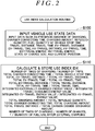
- FIG. 2 is a flowchart illustrating an example of a use index calculation routine that is executed by the HVECU 70.
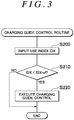
- FIG. 3 is a flowchart illustrating an example of a charging guide control routine that is executed by the HVECU 70.
- the routine is executed at a predetermined start timing.
- the predetermined start timing is a timing when the system is turned on (the system is started), a timing when the system is turned off (the system is stopped), a timing when charging of the battery 50 is completed by connecting the charging inlet 61 (the charger 60) to the charger cable 69a (the external power source 69), or a timing when the fuel tank 25 is refueled.
- this routine is executed when the system is turned on (the system is started).
- the HVECU 70 When the use index calculation routine is executed, the HVECU 70 first performs a process of inputting data that reflect vehicle use states and are necessary for calculating a use index IDX in a predetermined time period (step S100).
- a predetermined time period it is possible to use a time period that is determined in advance in terms of time, such as one month or two months, a time period that is determined in advance in terms of occasion, such as during 20 trips or during 30 trips, or the like.
- the "trip” is defined as follows: one trip is a period from when the system of the hybrid vehicle is turned on (the system is started) to when the system is turned off (the system is stopped).
- data that reflect vehicle use states there can be cited, as data from the system-off timing of the last trip to the system-on timing of the current trip, the presence/absence of charging of the battery 50 by the charger 60 (the presence/absence of external charging), a charging time (a charger connecting time) for which the charging inlet 61 (the charger 60) is connected to the charger cable 69a (the external power source 69), and a charging amount of the battery 50 by the charger 60.
- a refueled quantity a fuel quantity Qf
- a vehicle stop time from the system-off timing of the last trip to the system-on timing of the current trip a travel distance in the last trip, and a travel time in the last trip.
- an EV-travel distance in the last trip an EV-travel time in the last trip, an HV-travel distance in the last trip, and an HV-travel time in the last trip.
- an energy (an EV-travel energy) consumed by EV travel in the last trip an energy (an HV-travel energy) consumed by HV travel in the last trip, a state of charge SOC, a current position of the vehicle, and so on.
- the HVECU 70 calculates a use index IDX using the input data and stores the calculated use index IDX in the RAM (not shown) and the flash memory 72 of the HVECU 70 (step S110), and ends this routine.
- the use index IDX is calculated such that the greater the use index IDX, the better the use of charging (external charging) of the battery 50 by the charger 60.
- the use index IDX is calculated as one of (1) to (14) given below or is calculated based on one or a plurality of (1) to (14).
- the use index IDX is calculated as a ratio of the number of times of charging to the number of trips (the number of times of charging / the number of trips), or is calculated based on the ratio.
- the number of times of charging can be obtained by counting based on the presence/absence of external charging in the predetermined time period.
- the presence/absence of external charging can be detected by determining whether or not the charging inlet 61 (the charger 60) is connected to the charger cable 69a (the external power source 69) based on a connection signal SWC from the connection switch 62, or by determining an increase in the state of charge SOC of the battery 50.
- the number of trips can be obtained by counting every time the system is turned on in the predetermined time period.
- the use index IDX is calculated as a ratio (total charger connecting time / total vehicle stop time) of a total time for which the charger 60 is connected to the external power source 69 to a total time for which the vehicle is stopped with system off, or is calculated based on the ratio.
- the total charger connecting time can be obtained by integrating the charging time for which the charging inlet 61 (the charger 60) is connected to the charger cable 69a (the external power source 69) in the predetermined time period.
- the total vehicle stop time can be obtained by integrating the vehicle stop time between the trips in the predetermined time period.
- the use index IDX is calculated as a ratio (total EV-travel distance / total HV-travel distance) of a total distance of EV travel to a total distance of HV travel, or is calculated based on the ratio.
- the total EV-travel distance can be obtained by integrating the EV-travel distances in the trips in the predetermined time period.
- the total HV-travel distance can be obtained by integrating the HV-travel distances in the trips in the predetermined time period.
- the use index IDX is calculated as a ratio (total EV-travel time / total HV-travel time) of a total time of EV travel to a total time of HV travel or is calculated based on the ratio.
- the total EV-travel time can be obtained by integrating the EV-travel time in the trips in the predetermined time period.
- the total HV-travel time can be obtained by integrating the HV-travel time in the trips in the predetermined time period.
- the use index IDX is calculated as a ratio (total EV-travel distance / total travel distance) of a total distance of EV travel to a total travel distance or is calculated based on the ratio.
- the total travel distance can be obtained by integrating the travel distances in the trips in the predetermined time period.
- the use index IDX is calculated as a ratio (total EV-travel time / total travel time) of a total time of EV travel to a total travel time or is calculated based on the ratio.
- the total travel time can be obtained by integrating the travel time in the trips in the predetermined time period.
- the use index IDX is calculated as a ratio (total charging amount / total refueled quantity) of a total charging amount of charging of the battery 50 by the charger 60 to a total refueled quantity to the fuel tank 25 or is calculated based on the ratio.
- the total charging amount can be obtained by integrating the charging amounts by external charging in the predetermined time period.
- the total refueled quantity can be obtained by integrating the refueled quantities in the predetermined time period.
- the use index IDX is calculated as a ratio (integrated externally-charged energy value / integrated travel-consumed energy value) of an integrated value of an energy charged to the battery 50 by electric power from the external power source 69 to an integrated value of an energy consumed by travel.
- the integrated externally-charged energy value can be obtained by integrating the charging amounts by external charging in the predetermined time period.
- the integrated travel-consumed energy value can be obtained as an integrated value of EV-travel energy and HV-travel energy.
- the EV-travel energy or the HV-travel energy can be obtained by time-integrating the product of a vehicle weight M and a vehicle speed V ( ⁇ M ⁇ Vdt) during EV travel or HV travel.
- the use index IDX is calculated as a ratio (integrated EV-travel energy value / integrated HV-travel energy value) of an integrated value of an energy consumed by EV travel to an integrated value of an energy consumed by HV travel or is calculated based on the ratio.
- the integrated EV-travel energy value can be obtained by integrating the EV-travel energy.
- the integrated HV-travel energy value can be obtained by integrating the HV-travel energy.
- the use index IDX is calculated as a total time (total charger connecting time) for which the charger 60 is connected to the external power source 69 or is calculated based on the total time.
- the total charger connecting time can be obtained by integrating the time for which the charging inlet 61 (the charger 60) is connected to the charger cable 69a (the external power source 69) in the predetermined time period.
- the use index IDX is calculated as a total charging amount of the battery 50 by the charger 60 or is calculated based on the total charging amount. T The total charging amount can be obtained by integrating the charging amounts by external charging in the predetermined time period.
- the use index IDX is used as a ratio (total travel distance / total carbon dioxide discharge amount) of a traveled total travel distance to a total discharge amount of carbon dioxide or is calculated based on the ratio.
- the total carbon dioxide discharge amount can be calculated as the sum of the product of the total refueled quantity and a fuel coefficient and the product of the total charging amount and an external charging coefficient.
- the use index IDX is calculated as a ratio (the number of times of charging in chance / the number of chances) of, to the number of charging chances (the number of chances) in a state where the vehicle can be externally charged, the number of times of carrying out external charging in that state (the number of times of charging in chance), or is calculated based on the ratio.
- the number of chances can be obtained by counting the number of times in which the vehicle was parked in a parking lot at home or in a battery charging station in the predetermined time period. Whether or not the vehicle is parked in the parking lot at home or in the battery charging station can be determined by determining whether or not the current position of the vehicle from the navigation device 90 is the parking lot at home or the battery charging station. The number of times of charging can be obtained by counting the number of times in which the vehicle was parked in the parking lot at home or in the battery charging station and charged in the predetermined time period.
- the use index IDX is calculated as an inverse (1 / quantity of fuel use after external charging) of a quantity of fuel use by the internal combustion engine after external charging or is calculated based on the ratio. The quantity of fuel use after external charging can be calculated based on a fuel quantity Qf when the external charging was carried out, a refueled quantity, and a current fuel quantity Qf.
- the routine is performed when the hybrid vehicle 20 is pared at a battery charging point.
- the HVECU 70 inputs the use index IDX (step S200) and compares the use index IDX thus input with a threshold Iref (step S210).
- the threshold value Iref is determined in advance as a threshold value for determining that the degree of use of external charging is low (the use of external charging is not performed preferably).
- step S220 When the use index IDX is the threshold Iref or more, it is determined that the degree of use of external charging is not low, and this routine is finished. In the meantime, when the use index IDX is less than the threshold Iref, it is determined that the degree of use of external charging is low, and a charging guide control to promote the use of external charging is executed (step S220). Here, the routine is finished.
- the charging guide control at least one of the following is performed in the present embodiment: displaying of a message "please carry out external charging” or the like (information to promote the use of external charging) on the display device 92; an audio output from the speaker 93; automatic opening of the charging inlet lid 63; permission (preorder) of setting of pre-air conditioning by the air-conditioning device 91 at the time when the charging inlet 61 (the charger 60) is connected to the charger cable 69a (the external power source 69); and output of an alarm from the speaker 93 until the charging inlet 61 (the charger 60) is connected to the charger cable 69a (the external power source 69).
- the charging guide control is executed at the time of parking at a battery charging point, thereby making it possible to promote a driver to use external charging. As a result, the use of external charging can be promoted.
- the charging guide control in addition to or instead of the above process, the following control is conceivable: when the charging inlet 61 (the charger 60) is connected to the charger cable 69a (the external power source 69), ready-off, that is, system off (system stop) is permitted or executed; or when the charging inlet 61 (the charger 60) is connected to the charger cable 69a (the external power source 69), key lock is enabled.
- the charging guide control to promote the use of external charging is executed at the time of parking at a battery charging point, such as at home or in a charging stand, where the external charging is performable.
- a battery charging point such as at home or in a charging stand
- the external charging is performable.
- the charging guide control is executed at the time of parking at the battery charging point where the external charging is performable.
- the home 96 is provided with a locking release device 97 that prohibits unlocking of an entrance, a lamp 98a, a speaker 98b, a control device 99, and the like.
- the control device 99 controls the locking release device 97, the lamp 98a, and the speaker 98b and can communicate with the HVECU 70 via the communication device 94.
- the hybrid vehicle 20 transmits the use index IDX or a request of the charging guide control to the control device 99.
- the control device 99 receives the use index IDX or the request of the charging guide control, the control device 99 performs, as the charging guide control, prohibition of unlocking of the entrance by the locking release device 97, lighting of the lamp 98a, or output of an alarm from the speaker 98b until the charging inlet 61 (the charger 60) is connected to the charger cable 69a (the external power source 69).
- the control device 99 performs, as the charging guide control, prohibition of unlocking of the entrance by the locking release device 97, lighting of the lamp 98a, or output of an alarm from the speaker 98b until the charging inlet 61 (the charger 60) is connected to the charger cable 69a (the external power source 69).
- the vehicle external device is not limited to the home 96 provided with the locking release device 97, the lamp 98a, the speaker 98b, the control device 99, and the like. Accordingly, the same configuration as above is applicable even at the time of parking at a battery charging point except the home 96.
- the HVECU 70 executes the use index calculation routine of FIG. 2 and the charging guide control routine of FIG. 3 .
- the HVECU 70 may execute the use index calculation routine of FIG. 2 and a charging guide control routine of FIG. 5 instead of the charging guide control routine of FIG. 3 .
- the HVECU 70 inputs an use index IDX (step S300), similarly to the processes of steps S200 and S210 of the charging guide control routine of FIG. 3 , and compares the use index IDX thus input with the threshold Iref (step S310).
- the use index IDX is the threshold Iref or more, it is determined that the degree of use of external charging is not low, and this routine is finished.
- the HVECU 70 determines that the degree of use of external charging is low and determines whether or not a prohibition condition of the charging guide control is established (step S320).
- the prohibition condition it is possible to use at least one of a condition that does not require execution of external charging and a condition that cannot carry out external charging.
- At least one of the following conditions can be used: a condition that the battery 50 is fully charged; and a condition that a current battery charging point is not a predetermined battery charging point including the home. It is possible to determine whether or not the battery 50 is fully charged by use of the state of charge SOC of the battery 50 from the battery ECU 52. It is possible to determine whether or not the current battery charging point is the predetermined (registered) battery charging point including the home, by use of data from the navigation device 90.
- At least one of the following conditions can be used: a condition that the charging facility 68 of the battery charging point is during a power failure; a condition that the external power source 69 has an abnormality; and a condition that a connection with the external power source 69 is occupied by another vehicle. It is possible to determine, by use of a result of a communication with the charging facility 68, whether or not the charging facility 68 of the battery charging point is during a power failure, whether or not the external power source 69 has an abnormality, and whether or not the connection (the charger cable 69a) with the external power source 69 is occupied by another vehicle.
- step S330 When the prohibition condition of the charging guide control is not established, the charging guide control is executed (step S330), and the routine is finished. In the meantime, when the prohibition condition of the charging guide control is established, the charging guide control is not executed, and the routine is finished.
- the charging guide control is not executed, and the routine is finished.
- the hybrid vehicle 20 of the embodiment includes the charger 60 that charges the battery 50 by connecting the charging inlet 61 (the charger 60) to the charger cable 69a (the external power source 69), but may include a charger that charges the battery 50 by receiving electric power from the external power source 69 in a non-contact manner.
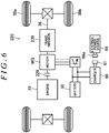
- the engine 22, the motor MG1, and the drive shaft 36 are connected to the planetary gear 30, and the motor MG2 is connected to the drive shaft 36.
- a motor MG may be connected to a drive shaft 36 connected to driving wheels 38a, 38b via a transmission 230
- an engine 22 may be connected to a rotating shaft of the motor MG via a clutch 229, so that power from the engine 22 is output to the drive shaft 36 via the rotating shaft of the motor MG and the transmission 230, and power from the motor MG is output to the drive shaft via the transmission 230.
- a configuration of what is called a series hybrid vehicle may be employed. That is, any configuration may be employed, provided that the vehicle is a hybrid vehicle including an engine, a motor, a battery, and a charger that charges the battery by being connected to an external power source.
- the engine 22 corresponds to an "engine”
- the fuel tank 25 corresponds to a "fuel tank”
- the motor MG2 corresponds to a "motor”
- the battery 50 corresponds to a "battery”
- the charger 60 corresponds to a “charger”
- the HVECU 70 that executes the use index calculation routine of FIG. 2 and the charging guide control routine of FIG. 3
- the engine ECU 24, the motor ECU 40, and the battery ECU 52 correspond to an "electronic control unit.”
- the HVECU 70, the engine ECU 24, the motor ECU 40, and the battery ECU 52 may be included in one electronic control unit.
- the present invention is usable in a manufacture industry of the hybrid vehicle 20, and the like.
- an electronic control unit determines that the degree of use of external charging is low, and executes a charging guide control to promote the use of external charging at the time of parking at a battery charging point, such as at home (96) or in a battery charging station, where the external charging is performable.
- a battery charging point such as at home (96) or in a battery charging station, where the external charging is performable.
Applications Claiming Priority (1)
| Application Number | Priority Date | Filing Date | Title |
|---|---|---|---|
| JP2016069249A JP6399026B2 (ja) | 2016-03-30 | 2016-03-30 | ハイブリッド自動車および連携システム |
Publications (1)
| Publication Number | Publication Date |
|---|---|
| EP3228516A1 true EP3228516A1 (de) | 2017-10-11 |
Family
ID=58448421
Family Applications (1)
| Application Number | Title | Priority Date | Filing Date |
|---|---|---|---|
| EP17163207.8A Pending EP3228516A1 (de) | 2016-03-30 | 2017-03-28 | Hybridfahrzeug. kooperationssystem und steuerungsverfahren für ein hybridfahrzeug |
Country Status (4)
| Country | Link |
|---|---|
| US (1) | US10328816B2 (de) |
| EP (1) | EP3228516A1 (de) |
| JP (1) | JP6399026B2 (de) |
| CN (1) | CN107415711B (de) |
Families Citing this family (17)
| Publication number | Priority date | Publication date | Assignee | Title |
|---|---|---|---|---|
| JP6361132B2 (ja) * | 2013-12-24 | 2018-07-25 | トヨタ自動車株式会社 | 非接触電力伝送システム、充電ステーション、および車両 |
| JP6060195B2 (ja) * | 2015-03-06 | 2017-01-11 | 本田技研工業株式会社 | 車両駐車制御装置 |
| JP6489054B2 (ja) * | 2016-03-30 | 2019-03-27 | トヨタ自動車株式会社 | ハイブリッド自動車 |
| JP2017178083A (ja) * | 2016-03-30 | 2017-10-05 | トヨタ自動車株式会社 | ハイブリッド自動車 |
| JP6758879B2 (ja) * | 2016-03-31 | 2020-09-23 | 株式会社東芝 | 切換制御装置および切換制御方法 |
| KR20180004388A (ko) * | 2016-07-03 | 2018-01-11 | 삼성전자주식회사 | 단말장치, 입력장치 및 그 전원 제어방법 |
| US10439427B2 (en) * | 2017-08-03 | 2019-10-08 | Ford Global Technologies, Llc | Determining a fuel quantity to charge a vehicle battery |
| JP6992459B2 (ja) * | 2017-12-05 | 2022-01-13 | トヨタ自動車株式会社 | ハイブリッド自動車およびこれに搭載される制御装置 |
| JP6984555B2 (ja) * | 2018-07-10 | 2021-12-22 | トヨタ自動車株式会社 | サーバ、車両および充電情報提供方法 |
| KR102586460B1 (ko) * | 2019-03-07 | 2023-10-06 | 현대자동차주식회사 | 배터리 사용 습관 및 배터리 방전 경향 예측 시스템 |
| JP7196719B2 (ja) * | 2019-03-26 | 2022-12-27 | トヨタ自動車株式会社 | 電動車両用の制御装置 |
| JP7164494B2 (ja) * | 2019-07-26 | 2022-11-01 | トヨタ自動車株式会社 | 充放電マネージメントシステム |
| JP7347396B2 (ja) * | 2020-10-27 | 2023-09-20 | トヨタ自動車株式会社 | ハイブリッド車両 |
| US20220258642A1 (en) * | 2021-02-15 | 2022-08-18 | Ford Global Technologies, Llc | Systems and methods for providing in-flight charging of electrified vehicles |
| US20220379743A1 (en) * | 2021-05-28 | 2022-12-01 | Ford Global Technologies, Llc | Systems and methods for providing bidirectional charging between electrified vehicles and electrified recreational vehicles |
| JP7459844B2 (ja) | 2021-06-17 | 2024-04-02 | トヨタ自動車株式会社 | 設定装置、表示制御装置及び車両制御システム |
| CN114312793B (zh) * | 2021-12-31 | 2023-07-21 | 上汽大众汽车有限公司 | 一种轨迹模式的匹配方法、匹配系统及计算机可读存储介质 |
Citations (5)
| Publication number | Priority date | Publication date | Assignee | Title |
|---|---|---|---|---|
| JPH0819114A (ja) | 1994-04-28 | 1996-01-19 | Mitsubishi Motors Corp | 燃料使用制限式ハイブリッド電気自動車 |
| DE102010003887A1 (de) * | 2010-04-13 | 2011-10-13 | Bayerische Motoren Werke Aktiengesellschaft | Verfahren und Vorrichtung zum Erzeugen eines Informationssignals für ein Kraftfahrzeug |
| US20120007554A1 (en) * | 2010-07-08 | 2012-01-12 | Denso Corporation | Vehicular charge apparatus |
| WO2012049559A2 (en) * | 2010-10-14 | 2012-04-19 | Toyota Jidosha Kabushiki Kaisha | Electromotive vehicle |
| US20130226379A1 (en) * | 2012-02-28 | 2013-08-29 | Makoto Hirai | Hybrid vehicle |
Family Cites Families (16)
| Publication number | Priority date | Publication date | Assignee | Title |
|---|---|---|---|---|
| JP3632634B2 (ja) * | 2001-07-18 | 2005-03-23 | 日産自動車株式会社 | ハイブリッド車両の制御装置 |
| JP4742749B2 (ja) | 2005-08-29 | 2011-08-10 | ソニー株式会社 | ディスク駆動装置及びその制御方法 |
| JP2007068358A (ja) * | 2005-09-01 | 2007-03-15 | Toyota Motor Corp | 電動車両 |
| JP2009126456A (ja) * | 2007-11-27 | 2009-06-11 | Fujitsu Ten Ltd | ハイブリッド車両の制御装置 |
| JP4466726B2 (ja) * | 2007-11-29 | 2010-05-26 | トヨタ自動車株式会社 | エコポイント管理システム |
| JP2009214668A (ja) * | 2008-03-10 | 2009-09-24 | Toyota Motor Corp | 料金決定システム、サーバおよびハイブリッド車 |
| US7999665B2 (en) * | 2009-08-18 | 2011-08-16 | Ford Global Technologies, Llc | Plug-in vehicle having a recharging port with a state of charge indicator |
| JP5498201B2 (ja) * | 2010-02-26 | 2014-05-21 | 本田技研工業株式会社 | 電気自動車用の情報制御装置、電気自動車、及び充電時期案内方法 |
| JP5212548B2 (ja) * | 2010-08-10 | 2013-06-19 | トヨタ自動車株式会社 | 電力情報報知装置 |
| DE112011104788T5 (de) | 2011-01-28 | 2013-10-31 | Mitsubishi Electric Corporation | Ladeberatungsvorrichtung und fahrzeugeigenes Navigationssystem |
| JP2012244768A (ja) * | 2011-05-19 | 2012-12-10 | Suzuki Motor Corp | 車載充電システム |
| US8483899B2 (en) * | 2011-10-06 | 2013-07-09 | Ford Global Technologies, Llc | Vehicle guidance system |
| JP2013106504A (ja) * | 2011-11-17 | 2013-05-30 | Mitsubishi Electric Corp | 電動車両充電システムおよび車載警報装置 |
| US20140081490A1 (en) * | 2012-09-14 | 2014-03-20 | Plug-In Conversions Corporation | System and method of converting a standard hybrid vehicle into a plug-in hybrid electric vehicle (phev) |
| JP2014117066A (ja) * | 2012-12-10 | 2014-06-26 | Nippon Sharyo Seizo Kaisha Ltd | 大型搬送車両 |
| DE102013215208A1 (de) * | 2013-08-02 | 2015-02-05 | Ford Global Technologies, Llc | Verfahren und Vorrichtung zur Einparkunterstützung eines Fahrzeuges |
-
2016
- 2016-03-30 JP JP2016069249A patent/JP6399026B2/ja active Active
-
2017
- 2017-03-23 US US15/467,296 patent/US10328816B2/en active Active
- 2017-03-28 EP EP17163207.8A patent/EP3228516A1/de active Pending
- 2017-03-28 CN CN201710191551.4A patent/CN107415711B/zh active Active
Patent Citations (5)
| Publication number | Priority date | Publication date | Assignee | Title |
|---|---|---|---|---|
| JPH0819114A (ja) | 1994-04-28 | 1996-01-19 | Mitsubishi Motors Corp | 燃料使用制限式ハイブリッド電気自動車 |
| DE102010003887A1 (de) * | 2010-04-13 | 2011-10-13 | Bayerische Motoren Werke Aktiengesellschaft | Verfahren und Vorrichtung zum Erzeugen eines Informationssignals für ein Kraftfahrzeug |
| US20120007554A1 (en) * | 2010-07-08 | 2012-01-12 | Denso Corporation | Vehicular charge apparatus |
| WO2012049559A2 (en) * | 2010-10-14 | 2012-04-19 | Toyota Jidosha Kabushiki Kaisha | Electromotive vehicle |
| US20130226379A1 (en) * | 2012-02-28 | 2013-08-29 | Makoto Hirai | Hybrid vehicle |
Also Published As
| Publication number | Publication date |
|---|---|
| JP6399026B2 (ja) | 2018-10-03 |
| JP2017178079A (ja) | 2017-10-05 |
| CN107415711A (zh) | 2017-12-01 |
| US10328816B2 (en) | 2019-06-25 |
| CN107415711B (zh) | 2020-08-07 |
| US20170282740A1 (en) | 2017-10-05 |
Similar Documents
| Publication | Publication Date | Title |
|---|---|---|
| US10328816B2 (en) | Hybrid vehicle, cooperation system, and control method for hybrid vehicle | |
| US10336251B2 (en) | Hybrid vehicle | |
| US10328930B2 (en) | Hybrid vehicle | |
| EP3225490B1 (de) | Hybridfahrzeug | |
| US10946752B2 (en) | Hybrid vehicle | |
| CN111483454A (zh) | 车辆 | |
| EP3225485A1 (de) | Hybridfahrzeug | |
| JP7010039B2 (ja) | ハイブリッド自動車 | |
| JP6512151B2 (ja) | ハイブリッド自動車 | |
| CN109941267B (zh) | 混合动力汽车及其所搭载的控制装置 | |
| JP6642206B2 (ja) | ハイブリッド自動車 | |
| JP7010043B2 (ja) | ハイブリッド自動車 | |
| JP7067004B2 (ja) | ハイブリッド自動車 | |
| JP6939628B2 (ja) | 車両の制御装置 | |
| JP6969419B2 (ja) | ハイブリッド自動車 | |
| JP2017178081A (ja) | ハイブリッド自動車 | |
| JP2023021199A (ja) | ハイブリッド車の制御装置 |
Legal Events
| Date | Code | Title | Description |
|---|---|---|---|
| PUAI | Public reference made under article 153(3) epc to a published international application that has entered the european phase |
Free format text: ORIGINAL CODE: 0009012 |
|
| STAA | Information on the status of an ep patent application or granted ep patent |
Free format text: STATUS: REQUEST FOR EXAMINATION WAS MADE |
|
| 17P | Request for examination filed |
Effective date: 20170328 |
|
| AK | Designated contracting states |
Kind code of ref document: A1 Designated state(s): AL AT BE BG CH CY CZ DE DK EE ES FI FR GB GR HR HU IE IS IT LI LT LU LV MC MK MT NL NO PL PT RO RS SE SI SK SM TR |
|
| AX | Request for extension of the european patent |
Extension state: BA ME |
|
| STAA | Information on the status of an ep patent application or granted ep patent |
Free format text: STATUS: EXAMINATION IS IN PROGRESS |
|
| 17Q | First examination report despatched |
Effective date: 20210226 |
|
| STAA | Information on the status of an ep patent application or granted ep patent |
Free format text: STATUS: EXAMINATION IS IN PROGRESS |