EP3228376B1 - Filtermodul mit einem filterelement und einem befestigungsrahmen und luftfilteranlage mit einem filtermodul - Google Patents
Filtermodul mit einem filterelement und einem befestigungsrahmen und luftfilteranlage mit einem filtermodul Download PDFInfo
- Publication number
- EP3228376B1 EP3228376B1 EP17159282.7A EP17159282A EP3228376B1 EP 3228376 B1 EP3228376 B1 EP 3228376B1 EP 17159282 A EP17159282 A EP 17159282A EP 3228376 B1 EP3228376 B1 EP 3228376B1
- Authority
- EP
- European Patent Office
- Prior art keywords
- filter
- filter module
- sealing element
- sealing
- mounting frame
- Prior art date
- Legal status (The legal status is an assumption and is not a legal conclusion. Google has not performed a legal analysis and makes no representation as to the accuracy of the status listed.)
- Active
Links
Images


Classifications
-
- B—PERFORMING OPERATIONS; TRANSPORTING
- B01—PHYSICAL OR CHEMICAL PROCESSES OR APPARATUS IN GENERAL
- B01D—SEPARATION
- B01D46/00—Filters or filtering processes specially modified for separating dispersed particles from gases or vapours
- B01D46/0002—Casings; Housings; Frame constructions
- B01D46/0004—Details of removable closures, lids, caps or filter heads
-
- B—PERFORMING OPERATIONS; TRANSPORTING
- B01—PHYSICAL OR CHEMICAL PROCESSES OR APPARATUS IN GENERAL
- B01D—SEPARATION
- B01D46/00—Filters or filtering processes specially modified for separating dispersed particles from gases or vapours
- B01D46/0002—Casings; Housings; Frame constructions
- B01D46/0005—Mounting of filtering elements within casings, housings or frames
-
- B—PERFORMING OPERATIONS; TRANSPORTING
- B01—PHYSICAL OR CHEMICAL PROCESSES OR APPARATUS IN GENERAL
- B01D—SEPARATION
- B01D46/00—Filters or filtering processes specially modified for separating dispersed particles from gases or vapours
- B01D46/10—Particle separators, e.g. dust precipitators, using filter plates, sheets or pads having plane surfaces
-
- B—PERFORMING OPERATIONS; TRANSPORTING
- B01—PHYSICAL OR CHEMICAL PROCESSES OR APPARATUS IN GENERAL
- B01D—SEPARATION
- B01D46/00—Filters or filtering processes specially modified for separating dispersed particles from gases or vapours
- B01D46/52—Particle separators, e.g. dust precipitators, using filters embodying folded corrugated or wound sheet material
- B01D46/521—Particle separators, e.g. dust precipitators, using filters embodying folded corrugated or wound sheet material using folded, pleated material
- B01D46/522—Particle separators, e.g. dust precipitators, using filters embodying folded corrugated or wound sheet material using folded, pleated material with specific folds, e.g. having different lengths
-
- B—PERFORMING OPERATIONS; TRANSPORTING
- B60—VEHICLES IN GENERAL
- B60H—ARRANGEMENTS OF HEATING, COOLING, VENTILATING OR OTHER AIR-TREATING DEVICES SPECIALLY ADAPTED FOR PASSENGER OR GOODS SPACES OF VEHICLES
- B60H3/00—Other air-treating devices
- B60H3/06—Filtering
-
- F—MECHANICAL ENGINEERING; LIGHTING; HEATING; WEAPONS; BLASTING
- F24—HEATING; RANGES; VENTILATING
- F24F—AIR-CONDITIONING; AIR-HUMIDIFICATION; VENTILATION; USE OF AIR CURRENTS FOR SCREENING
- F24F13/00—Details common to, or for air-conditioning, air-humidification, ventilation or use of air currents for screening
- F24F13/28—Arrangement or mounting of filters
-
- B—PERFORMING OPERATIONS; TRANSPORTING
- B01—PHYSICAL OR CHEMICAL PROCESSES OR APPARATUS IN GENERAL
- B01D—SEPARATION
- B01D2265/00—Casings, housings or mounting for filters specially adapted for separating dispersed particles from gases or vapours
- B01D2265/02—Non-permanent measures for connecting different parts of the filter
- B01D2265/028—Snap, latch or clip connecting means
-
- B—PERFORMING OPERATIONS; TRANSPORTING
- B01—PHYSICAL OR CHEMICAL PROCESSES OR APPARATUS IN GENERAL
- B01D—SEPARATION
- B01D2271/00—Sealings for filters specially adapted for separating dispersed particles from gases or vapours
- B01D2271/02—Gaskets, sealings
-
- B—PERFORMING OPERATIONS; TRANSPORTING
- B01—PHYSICAL OR CHEMICAL PROCESSES OR APPARATUS IN GENERAL
- B01D—SEPARATION
- B01D2271/00—Sealings for filters specially adapted for separating dispersed particles from gases or vapours
- B01D2271/02—Gaskets, sealings
- B01D2271/022—Axial sealings
-
- B—PERFORMING OPERATIONS; TRANSPORTING
- B01—PHYSICAL OR CHEMICAL PROCESSES OR APPARATUS IN GENERAL
- B01D—SEPARATION
- B01D2271/00—Sealings for filters specially adapted for separating dispersed particles from gases or vapours
- B01D2271/02—Gaskets, sealings
- B01D2271/027—Radial sealings
-
- B—PERFORMING OPERATIONS; TRANSPORTING
- B01—PHYSICAL OR CHEMICAL PROCESSES OR APPARATUS IN GENERAL
- B01D—SEPARATION
- B01D2279/00—Filters adapted for separating dispersed particles from gases or vapours specially modified for specific uses
- B01D2279/40—Filters adapted for separating dispersed particles from gases or vapours specially modified for specific uses for cleaning of environmental air, e.g. by filters installed on vehicles or on streets
-
- B—PERFORMING OPERATIONS; TRANSPORTING
- B01—PHYSICAL OR CHEMICAL PROCESSES OR APPARATUS IN GENERAL
- B01D—SEPARATION
- B01D46/00—Filters or filtering processes specially modified for separating dispersed particles from gases or vapours
-
- B—PERFORMING OPERATIONS; TRANSPORTING
- B01—PHYSICAL OR CHEMICAL PROCESSES OR APPARATUS IN GENERAL
- B01D—SEPARATION
- B01D46/00—Filters or filtering processes specially modified for separating dispersed particles from gases or vapours
- B01D46/42—Auxiliary equipment or operation thereof
-
- F—MECHANICAL ENGINEERING; LIGHTING; HEATING; WEAPONS; BLASTING
- F02—COMBUSTION ENGINES; HOT-GAS OR COMBUSTION-PRODUCT ENGINE PLANTS
- F02M—SUPPLYING COMBUSTION ENGINES IN GENERAL WITH COMBUSTIBLE MIXTURES OR CONSTITUENTS THEREOF
- F02M35/00—Combustion-air cleaners, air intakes, intake silencers, or induction systems specially adapted for, or arranged on, internal-combustion engines
- F02M35/02—Air cleaners
Definitions
- the invention relates to a filter module with a filter element for filtering a fluid and a mounting frame and an air filter system with a filter module, in particular for cabin air filtration, in particular of a vehicle.
- a filter element which is used, for example, as an automotive interior air filter or filter element for a motor vehicle air conditioning system, serves to filter the outside of the interior of the vehicle conducted and treated air by means of a suitable filter.
- a suitable filter for example, particle or odor filters are used or combinations thereof, which filter out the particles contained in the air and inherent odors from the ambient air.
- the effectiveness of a filter or of such a filter system also depends on the fact that the filter system is mounted in the correct position in the filter housing or an associated filter receptacle of the filter housing.
- a flat filter which comprises a housing section, which forms part of the air line.
- An object of the invention is to provide a filter module with a mounting frame and a filter element for filtering a fluid, in particular for air filtering, in particular for cabin air filtration, which allows reliably insert the filter element tightly in an air filter system and remove again.
- Another object is to provide an air filter system for filtering a fluid to receive such a replaceable filter module.
- a filter module for filtering a fluid having at least one filter element and a preferably fixedly connected to the filter element mounting frame having a circumferential first sealing element, which is arranged on an outer side of the frame wall of the mounting frame, wherein the mounting frame has on its outer side at least one latching element, and wherein a second sealing element for sealing between the raw side and clean side of the filter element or on the mounting frame is arranged, which is guided with locking the at least one latching element in its sealing position, wherein the first sealing element as Axialêtlement and the second sealing element is designed as a radial sealing element.
- the further object is achieved by an air filter system which is provided for receiving such a replaceable filter module.
- a filter module for filtering a fluid comprising at least one filter element with a filter bellows from a filter medium with a designated raw side and one of these opposite intended clean side, a mounting frame which is connected to the filter element and the one edge of the filter element with a frame wall surrounding at least partially surrounds, a circumferential first sealing element, which is arranged on an outer side of the frame wall of the mounting frame, wherein the mounting frame has on its outer side at least one latching element, wherein a second sealing element for sealing between the raw side and clean side of the filter element is arranged with the locking of the at least one locking element in its sealing position can be guided.
- the filter module when installed in an air filter system compensate for component tolerances and at the same time seal the raw side of the filter element against the clean side.
- the first sealing element on the mounting frame is used for tolerance compensation and a vibration-proof attachment in its installed position in an air filter system, while the second sealing element is provided for sealing the raw side against the clean side.
- the filter module can be locked in its installed position and sealed at the same time.
- the filter module can be locked directly to a sheet metal part of the air filter system.
- the first sealing element may be a foam material.
- the filter bellows are preferably a flat filter bellows, i. H. the filter bellows has mutually parallel, planar inflow and outflow surfaces on the raw side and the clean side, which are formed by the inflow or outflow-side fold edges. The flow takes place substantially perpendicular to the inlet and outlet surface.
- the mounting frame encloses the inlet and outlet surfaces and / or the raw side and the clean side of the filter bellows.
- the at least one latching element may preferably be located within the first sealing element, i. H. be seen perpendicular to the flow direction between the filter bellows and the first sealing element.
- the first sealing element according to the invention is an axial sealing element.
- axial is meant a direction which is parallel to the installation direction.
- the installation direction for the preferred embodiments corresponds to the direction of flow through the filter element, in particular the flat filter bellows.
- the first sealing element is preferably designed to be in the axial direction, d. H.
- d. H Preferably in the installation direction or in the flow direction and / or seal perpendicular to the arrival and downstream surfaces, d. H.
- the first sealing element is axially compressed by the movement of the filter element or the filter module.
- the second sealing element according to the invention is a radial sealing element.
- radial is meant a direction which runs in a plane perpendicular to the installation direction.
- the second sealing element is preferably designed to seal in the radial direction, ie preferably perpendicular to the installation direction or to the flow direction and / or parallel to the arrival and downstream surfaces, ie sealingly applied in the radial direction and elastically deformable.
- the second sealing element is carried out in excess in relation to a radial sealing seat, so that a particularly elastic deformation takes place perpendicular to the installation direction, when the second sealing element is transferred to the sealing position.
- a radial sealing element is independent of the axial position, so that installation tolerances can be compensated, which occur in particular to a greater extent when the contact surfaces of the first and second sealing element are arranged on different opposing parts, which have a positional tolerance to each other.
- the second sealing element is arranged on the side facing away from the first sealing element side of the at least one locking element and preferably spaced therefrom. It is also independent of the o. G. Characteristics particularly advantageous if the second sealing element does not project beyond the latching elements in order not to interfere with the installation of the corresponding latching devices of a housing, in particular the edge of an installation opening. In other words, the at least one latching element preferably projects beyond the second sealing device in the radial direction. Accordingly, it is further advantageous, on the housing side, to set back radially a sealing seat for contacting the second sealing device with respect to the installation opening, ie. H. smaller than the installation opening.
- At least one handle may be provided on the mounting frame of the filter module, with which the at least one locking element for removal from an installation position is detachable by the mounting frame on the handle from the installation position is removable.
- the filter module can be performed in its installed position in an air filter system and locked there and removed from the mounting position again.
- the first sealing element may be circumferentially closed on the frame wall of the mounting frame and does not have to be on the Locking element, or on the locking elements, if several locking elements are provided, be interrupted. This simplifies the assembly and disassembly of the filter module.
- a plurality of locking elements may be provided on the frame wall.
- the mounting frame may be glued to the filter element.
- a polyurethane adhesive or the like is advantageous.
- the filter element may be preassembled with the mounting frame and replaced with the mounting frame. It is essential and preferred that the filter element with the mounting frame firmly, d. H. captive and preferably sealingly connected to the mounting frame, so that they can be installed and removed as a unit position independent and not the filter element, in particular not in the installation direction and / or flow direction, can fall out of the mounting frame.
- the frame wall may be formed as a double wall, with a closed inner wall and the outside as the outer wall with the at least one locking element.
- the inner wall of the frame wall tightly closed circumferentially abut the sides of the filter element, while the outer wall can be suitably interrupted for the at least one latching element or for a plurality of latching elements.
- the at least one latching element may have a latching nose with two obliquely opposite in the axial direction inclined surfaces, which is arranged on a flexible tab in the outside of the frame wall.
- an inclination of the mutually opposite in the axial direction inclined surfaces can be chosen so that with the one inclined surface a reliable locking of the locking elements and with the other, opposite inclined surface releasing the locking is possible if the filter module on the handle of the mounting frame from his Installation position is pulled.
- the two inclined surfaces each enclose with the frame wall an angle of at most 90 °, preferably of at most 85 °, more preferably of at most 80 °.
- the angle is chosen so that a secure locking is possible.
- a disassembly force for disassembly of the filter module and a mounting force for mounting the filter module is dependent on the number of locking elements, of one Inclination angle of the corresponding inclined surface relative to the frame wall, the width of the locking elements and the thickness of the locking element.
- the elements for the desired forces can be adjusted accordingly.
- the frame wall may be spaced with its lower edge from an upper edge of the second sealing element at a distance. This allows compensation of component tolerances.
- a laterally applied sideband may be arranged peripherally on the filter bellows surrounding lateral end faces, wherein the second sealing element is further preferably arranged on one outer side of the sideband as a circumferential sealing ring, and wherein the sideband has a tab projecting beyond the clean side of the filter bellows, which tab is folded back on the front sides V-shaped over the second sealing element.
- the tab is advantageously used for centering the filter module and as an insertion aid for the second sealing element in its sealing seat in the installed position.
- a part of the lateral sealing of the filter bellows in particular in a zigzag folded filter medium arranged sidebands, which projects beyond a lower edge of the filter bellows, which limits the clean side, be folded back and so V-shaped projecting to the attached side edges sideband , partially protrude over the sealing element.
- a sealing seat e.g. a filter housing or the like
- this V-shaped tab may be pressed against the sealing element and at least partially clamped between the sealing element and the sealing seat, so that the tab is thus firmly fixed to the seal seat.
- the second sealing element which may for example be formed from sponge rubber or cellular rubber and may be designed as a rectangular profile, is expediently glued to the sideband.
- the sealing element may have an adhesive layer, with which it may be glued to the sideband.
- the sealing element can also be applied directly to the sideband as a sealant bead. Since the cross section (width / length) of the filter element of the filter module is favorably chosen larger than the cross section of the sealing seat in the installed position, an overlap occurs and the sealing element is pressed into the sealing seat during insertion of the filter module. By overlapping the tab with the sealing element, the sealing element is pre-compressed and the compression achieved when inserting the filter module in the sealing seat without detachment of the sealing element.
- the tab can at least partially cover the second sealing element on an outer side. This ensures that when inserting the filter module in a sealing seat, the tab between the sealing element and the wall of the sealing seat is clamped and thus facilitates both the onset of the filter module by a pre-compression of the sealing element and an additional sealing effect can be done via the tab.
- an air filter system in particular an interior air filter system, in particular a vehicle, with a filter module according to the invention and a clean air duct, wherein the filter module is arranged interchangeable in an installed position and which filter module has a filter element in a mounting frame.
- the filter module can be locked with at least one locking element on its frame wall directly with a sheet metal component and again easily released from its installed position.
- the filter module can provide a tolerance compensation when installed in its installed position.
- An additional component for tolerance compensation can be dispensed with
- a first sealing element sealingly rest against a sheet metal frame, if at least one locking element on the mounting frame and at the same time a second sealing element on Filter element for sealing the raw side against the clean side sealingly against a sealing seat of an air inlet.
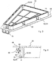
- FIG. 1 shows an exploded view of a filter module 100 for filtering a fluid with a filter element 10 and a mounting frame 60 according to an embodiment of the invention in an isometric view.
- FIG. 2 shows the filter module 100 in the assembled state for installation in its installed position.
- the filter module 100 comprises a filter element 10 with a filter bellows 12 made of a filter medium 14 with a designated raw side 52 and one of these opposite intended clean side 50.
- the mounting frame 60 is fixedly connected to the filter element 10, for example, glued, and circumferentially enclosing an edge 22 of the filter element 10 with a frame wall 62.
- the mounting frame 60 On its upper side, which forms the roßuft Organic File top of the filter module 100, the mounting frame 60 has a circumferential protruding edge 68th on, from which the frame wall 62 projects axially. Within the edge 68 of the mounting frame 60 has a grid with a large grid, which covers the filter element 10 in the assembled state.
- a circumferential first sealing element 40 is disposed on an outer side 64 of the frame wall 62 of the mounting frame 60 below the edge 68.
- the mounting frame 60 has on its outer side 64 a plurality of locking elements 80.
- the edge 68 is above the locking elements 80 via.
- the edge 68 is intended to abut against an installation opening, for example in a mounting plate, of the filter module 100.
- the locking elements 80 are hidden in the final installation position.
- a handle 70 is provided, with which the locking elements 80 can be removed for removal from an installation position by the mounting frame 60 on the handle 70 is removable from the installed position.
- a further grip element 72 may be provided which is opposite to the grip 70 Side of the mounting frame 60 may be arranged.
- the mounting frame 60 has a trapezoidal cross-section, with the handle 70 being located at the smallest side of the trapezoidal cross-section so that the filter module 70 can be easily pulled out of the mounting position.
- the filter element 10 comprises a flat filter bellows 12 made of a filter medium 14 with a designated raw side 52 and one of these opposite intended clean side 50.
- the filter bellows 12 has erected folds so that each fold edges lie in the clean side surface and the raw air side surface of the filter element 10.
- the lateral end faces of the filter element 10 are sealed with a circumferential sideband 28.
- a circumferential second sealing element 32 is arranged on the outside of the side band 28 .
- the sideband 28 has a tab 36 protruding beyond the clean side 50 of the filter bellows 12, which tab 36 is arranged folded over the sealing element 32 at the lateral end sides in a V-shaped manner.
- the sealing element 32 may consist of sponge rubber or cellular rubber, which has proven to be a particularly favorable sealing material with suitable elastic properties.
- the tab 36 covers the sealing element 32 on the outside slightly, since the tab 36 is formed to reach the pure side 50 facing edge of the sealing element 32 zoom.
- the side band 28 is expediently recessed or stamped to form the tab 36 on a circumference of the clean side 50 so as to be able to reliably fold back the tab.
- the side band 28 and the tab 36 comprise a non-woven fabric or a similar textile fabric, since these materials seal well and can be processed easily.
- the mounting frame 60 is connected to the filter element 10, wherein between the lower edge of the frame wall 62 and the upper edge of the second sealing element 32, a distance 46 is formed, which allows for installation in an installed position of the filter module 100, a compensation of component tolerances in the axial direction.
- FIG. 3 shows a bottom view of the mounting frame 60 of the filter module 100 after FIG. 1 .
- the frame wall 62 is formed as a double wall and has an outer wall as the outer side 64 and an inner wall 66.
- the inner wall is closed, while the outer wall is interrupted by the latching elements 80, in this example seven latching elements 80 which are arranged distributed on the circumference of the frame wall 62.
- FIG. 4 shows a detailed view of a locking element 80 of the mounting frame 60 FIG. 1 .
- the latching element 80 has a latching nose 82 with two inclined surfaces 86, 88, which is arranged on a flexible tab 84 in the outer side 64 of the frame wall 62.
- the upper inclined surface 86 has an angle ⁇ with respect to the axial direction perpendicular to the edge 68 of the mounting frame 60.
- the angle ⁇ together with the number of locking elements 80, their width and the thickness d of the tab 84 determines the disassembly force for the filter module 100 for removing the filter module 100 from its installed position.
- the lower inclined surface 88 has an angle ⁇ with respect to the axial direction.
- the angle ⁇ determines, together with the number of locking elements 80, the width and the thickness d of the tab 84, the mounting force for inserting the filter module 100 in its installed position.
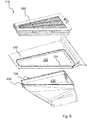
- FIG. 5 shows an exploded view of a filter module 100 and a section of an air filter system 110 with mounting plate 120 and clean air duct 130 into which the filter module 100 is to be inserted.
- the FIGS. 6 to 8 illustrate various stages when inserting the filter module 100 FIG. 1 in its installation position in the air filter system 110 on the basis of detailed views.
- the mounting plate 120 of the air filter system 110 has an opening 122 with a downwardly offset edge 124, at which the first sealing element 40 of the filter module 100 should come to rest.
- a trained as a hose clean air duct 130 has a sealing seat 134 for the second filter element 32 of the filter module 100.
- the clean air duct 130 is fixed with a fastening element (not shown) on the mounting plate 120 and with its opening 132 spaced therefrom.
- the filter module 100 is inserted with its clean air end with the second sealing element 32 ahead of the edge 124 in the opening 122 ( FIG. 6 ).
- the V-shaped tab 36 on the underside of the filter module 100 serves as an insertion aid.
- the respective latching element 80 comes with its latching nose 82 in contact with the edge 124 of the mounting plate 120 (FIG. FIG. 7 ) and deviates according to its insertion bevel (inclined surface 88, FIG. 4 ) elastically to the inner wall 66 of the frame wall 62 of the mounting frame 60.
- the filter module 100 can be further inserted into the opening 122 of the mounting plate 120.
- the lower end of the filter module 100 gets in contact with the opening 132 of the clean air duct 130, and is centered by means of the V-shaped folded tabs 36, which also serve as an insertion aid for the second sealing element 32 in the sealing seat 134.
- the tabs 36 cause a compression of the second sealing element 32, so that it can safely slide into the sealing seat 134.
- the latching nose 82 snaps with further insertion of the filter module 100 under the edge 124 of the mounting plate 120, while the second sealing element 32 further slides in the sealing seat 134 of the clean air duct 130 and the clean air duct 130 tightly seals ( FIG. 8 ).
- the first sealing element 40 is clamped between the edge 68 of the mounting frame and the mounting plate 120 and can generate in this way a bias voltage so that the filter module 100 is held vibration-proof in its final installed position.
Description
- Die Erfindung betrifft ein Filtermodul mit einem Filterelement zum Filtern eines Fluids und einem Befestigungsrahmen sowie eine Luftfilteranlage mit einem Filtermodul, insbesondere zur Innenraumluftfilterung, insbesondere eines Fahrzeugs.
- Ein Filterelement, das beispielsweise als Kfz-Innenraum-Luftfilter bzw. Filterelement für eine Kraftfahrzeugklimaanlage eingesetzt wird, dient dazu, die von außen in den Innenraum des Fahrzeugs geleitete und aufbereitete Luft mittels eines geeigneten Filters zu filtern. Dabei kommen beispielsweise Partikel- oder Geruchsfilter zum Einsatz oder Kombinationen davon, welche die in der Luft enthaltenen Partikel und inhärenten Gerüche aus der Umgebungsluft herausfiltern. Dabei hängt die Wirksamkeit eines Filters bzw. eines solchen Filtersystems auch davon ab, dass das Filtersystem in der richtigen Position in dem Filtergehäuse bzw. einer zugeordneten Filteraufnahme des Filtergehäuses montiert wird.
- Aus der
US 2006/0021932 A1 ist ein flacher Filter bekannt, welcher einen Gehäuseabschnitt umfasst, der einen Teil der Luftleitung mitbildet. Aus derDE 102013020382 A1 ist ein Filterelement mit einem Filtermedium und einem Rahmen zur Befestigung des Filterelements an oder in einem Filtergehäuse bekannt, wobei der Rahmen Rastelemente aufweist, mit denen der Rahmen zusammen mit dem Filterelement im Gehäuse verrastet werden kann. - Eine Aufgabe der Erfindung ist es, ein Filtermodul mit einem Befestigungsrahmen und einem Filterelement zum Filtern eines Fluids, insbesondere zur Luftfilterung, insbesondere zur Innenraumluftfilterung, zu schaffen, das es erlaubt, das Filterelement zuverlässig dicht in eine Luftfilteranlage einzusetzen und wieder zu entfernen.
- Eine weitere Aufgabe ist es, eine Luftfilteranlage zum Filtern eines Fluids zur Aufnahme eines solchen austauschbaren Filtermoduls zu schaffen.
- Die vorgenannte Aufgabe wird nach einem Aspekt der Erfindung gelöst von einem Filtermodul zum Filtern eines Fluids, mit wenigstens einem Filterelement und einem mit dem Filterelement bevorzugt fest verbundenen Befestigungsrahmen, das ein umlaufendes erstes Dichtelement aufweist, welches an einer Außenseite der Rahmenwand des Befestigungsrahmens angeordnet ist, wobei der Befestigungsrahmen an seiner Außenseite wenigstens ein Rastelement aufweist, und wobei ein zweites Dichtelement zum Dichten zwischen Rohseite und Reinseite am Filterelement oder am Befestigungsrahmen angeordnet ist, das mit Verrasten des wenigstens einen Rastelements in seine Dichtposition geführt ist, wobei das erste Dichtelement als Axialdichtelement und das zweite Dichtelement als Radialdichtelement ausgeführt ist.
- Nach einem anderen Aspekt der Erfindung wird die weitere Aufgabe durch eine Luftfilteranlage gelöst, die zur Aufnahme eines solchen auswechselbaren Filtermoduls vorgesehen ist.
- Günstige Ausgestaltungen und Vorteile der Erfindung ergeben sich aus den weiteren Ansprüchen, der Beschreibung und der Zeichnung.
- Es wird ein Filtermodul zum Filtern eines Fluids vorgeschlagen, umfassend wenigstens ein Filterelement mit einem Filterbalg aus einem Filtermedium mit einer bestimmungsgemäßen Rohseite und einer dieser gegenüberliegenden bestimmungsgemäßen Reinseite, einen Befestigungsrahmen, der mit dem Filterelement verbunden ist und der einen Rand des Filterelements mit einer Rahmenwand umlaufend wenigstens teilweise umschließt, ein umlaufendes erstes Dichtelement, welches an einer Außenseite der Rahmenwand des Befestigungsrahmens angeordnet ist, wobei der Befestigungsrahmen an seiner Außenseite wenigstens ein Rastelement aufweist, wobei ein zweites Dichtelement zum Dichten zwischen Rohseite und Reinseite am Filterelement angeordnet ist, das mit Verrasten des wenigstens einen Rastelements in seine Dichtposition führbar ist. Dadurch, dass der Befestigungsrahmen zwei Dichtelemente aufweist, kann das Filtermodul beim Einbau in eine Luftfilteranlage Bauteiltoleranzen ausgleichen und gleichzeitig die Rohseite des Filterelements gegen die Reinseite abdichten. Dabei dient das erste Dichtelement am Befestigungsrahmen dem Toleranzausgleich sowie einer vibrationsfesten Befestigung in seiner Einbauposition in einer Luftfilteranlage, während das zweite Dichtelement zum Abdichten von Rohseite gegen Reinseite vorgesehen ist. Das Filtermodul kann an seiner Einbauposition verrastet und gleichzeitig abgedichtet sein. Das Filtermodul kann direkt mit einem Blechbauteil der Luftfilteranlage verrastet sein. Beispielsweise kann das erste Dichtelement ein Schaummaterial sein.
- Bei dem Filterbalg handelt es sich bevorzugt um einen Flachfilterbalg, d. h. der Filterbalg hat zueinander parallele, ebene An- und Abströmflächen auf Rohseite und Reinseite, die durch die an- bzw. abströmseitigen Faltkanten gebildet werden. Die Durchströmung erfolgt dabei im Wesentlichen senkrecht zu An- und Abströmfläche. Der Befestigungsrahmen umschließt dabei die An- und Abströmflächen und/oder die Rohseite und die Reinseite des Filterbalgs.
- Das wenigstens eine Rastelement kann bevorzugt innerhalb des ersten Dichtelements, d. h. senkrecht zur Durchströmungsrichtung gesehen zwischen Filterbalg und erstem Dichtelement angeordnet sein.
- Das erste Dichtelement ist erfindungsgemäß ein Axialdichtelement. Als axial wird eine Richtung verstanden, die parallel zur Einbaurichtung ist. Vorliegend entspricht die Einbaurichtung für die bevorzugten Ausführungsformen der Durchströmungsrichtung des Filterelements, insbesondere des Flachfilterbalges. Somit ist das erste Dichtelement bevorzugt ausgelegt, um in Axialrichtung, d. h. bevorzugt in Einbaurichtung bzw. in Durchströmungsrichtung und/oder senkrecht zu den An- und Abströmflächen abzudichten, d. h. in Axialrichtung dichtend anleg- und elastisch verformbar zu sein. Das erste Dichtelement wird dabei durch die Bewegung des Filterelements bzw. des Filtermoduls axial verpresst.
- Das zweite Dichtelement ist erfindungsgemäß ein Radialdichtelement. Als radial wird eine Richtung verstanden, die in einer Ebene senkrecht zur Einbaurichtung verläuft. Somit ist das zweite Dichtelement bevorzugt ausgelegt, um in Radialrichtung, d. h. bevorzugt senkrecht zur Einbaurichtung bzw. zur Durchströmungsrichtung und/oder parallel zu den An- und Abströmflächen abzudichten, d. h. in Radialrichtung dichtend anleg- und elastisch verformbar zu sein. Das zweite Dichtelement wird dabei in Relation zu einem Radialdichtsitz im Übermaß ausgeführt, so dass eine insbesondere elastische Verformung senkrecht zur Einbaurichtung erfolgt, wenn das zweite Dichtelement in die Dichtposition überführt wird. Ein Radialdichtelement ist unabhängig von der Axialposition, so dass Einbautoleranzen ausgeglichen werden können, die insbesondere dann in größerem Maße auftreten, wenn die Anlageflächen des ersten und zweiten Dichtelements an unterschiedlichen Gegenteilen angeordnet sind, welche zueinander eine Lagetoleranz aufweisen.
- Hierbei, aber auch unabhängig von den o. g. Merkmalen, ist es besonders vorteilhaft, wenn das zweite Dichtelement auf der von dem ersten Dichtelement abgewandten Seite des mindestens einen Rastelements und bevorzugt beabstandet von diesen angeordnet ist. Ebenfalls ist es auch unabhängig von den o. g. Merkmalen besonders vorteilhaft, wenn das zweite Dichtelement die Rastelemente nicht überragt, um beim Einbau nicht mit den korrespondierenden Rasteinrichtungen eines Gehäuses, insbesondere die Kante einer Einbauöffnung, zu kollidieren. In anderen Worten überragt bevorzugt das mindestens eine Rastelement die zweite Dichteinrichtung in radialer Richtung. Dem folgend ist es weiter vorteilhaft, gehäuseseitig einen Dichtsitz zur Anlage der zweiten Dichteinrichtung bezüglich der Einbauöffnung radial zurückzuversetzen, d. h. kleiner als die Einbauöffnung auszuführen.
- Nach einer günstigen Ausgestaltung kann am Befestigungsrahmen des Filtermoduls wenigstens ein Haltegriff vorgesehen sein, mit dem das wenigstens eine Rastelement zum Entfernen aus einer Einbauposition lösbar ist, indem der Befestigungsrahmen am Haltegriff aus der Einbauposition entfernbar ist. Durch den Haltegriff kann das Filtermodul in seine Einbauposition in einer Luftfilteranlage geführt und dort verrastet werden und aus der Einbauposition wieder entfernt werden. Dadurch, dass die Verrastung des Filtermoduls an seiner Einbauposition durch den Haltegriff und nicht am wenigstens einen Rastelement selbst gelöst werden muss, kann das erste Dichtelement an der Rahmenwand des Befestigungsrahmens umlaufend geschlossen sein und muss nicht an dem Rastelement, oder an den Rastelementen, falls mehrere Rastelemente vorgesehen sind, unterbrochen sein. Dies vereinfacht die Montage und Demontage des Filtermoduls. Vorteilhafterweise können mehrere Rastelemente an der Rahmenwand vorgesehen sein.
- Nach einer günstigen Ausgestaltung kann der Befestigungsrahmen mit dem Filterelement verklebt sein. Vorteilhaft ist beispielsweise ein Polyurethan-Kleber oder dergleichen. Das Filterelement kann mit dem Befestigungsrahmen vormontiert sein und zusammen mit dem Befestigungsrahmen ausgewechselt werden. Hierbei ist es wesentlich und bevorzugt, dass das Filterelement mit dem Befestigungsrahmen fest, d. h. unverlierbar und bevorzugt dichtend mit dem Befestigungsrahmen verbunden ist, so dass sie als Einheit lageunabhängig ein- und ausbaubar sind und das Filterelement nicht, insbesondere nicht in Einbaurichtung und/oder Durchströmungsrichtung, aus dem Befestigungsrahmen fallen kann.
- Nach einer günstigen Ausgestaltung kann die Rahmenwand als Doppelwand ausgebildet sein, mit einer geschlossenen Innenwand und der Außenseite als Außenwand mit dem wenigstens einen Rastelement. Vorteilhaft kann die Innenwand der Rahmenwand dicht geschlossen umlaufend an den Seiten des Filterelements anliegen, während die Außenwand geeignet für das wenigstens eine Rastelement oder für mehrere Rastelemente unterbrochen sein kann.
Nach einer günstigen Ausgestaltung kann das wenigstens eine Rastelement eine Rastnase mit zwei sich in axialer Richtung gegenüberliegenden Schrägflächen aufweisen, die an einer flexiblen Lasche in der Außenseite der Rahmenwand angeordnet ist. Günstigerweise kann eine Neigung der einander in axialer Richtung gegenüberliegenden Schrägflächen so gewählt sein, dass mit der einen Schrägfläche eine zuverlässige Verrastung des oder der Rastelemente und mit der anderen, gegenüberliegenden Schrägfläche ein Lösen der Verrastung möglich ist, wenn das Filtermodul am Haltegriff des Befestigungsrahmens aus seiner Einbauposition gezogen wird. Vorteilhaft schließen die beiden Schrägflächen jeweils mit der Rahmenwand einen Winkel von höchstens 90°, vorzugsweise von höchstens 85°, besonders bevorzugt von höchstens 80° ein. Vorteilhaft ist der Winkel so gewählt, dass eine sichere Verrastung möglich ist. Eine Demontagekraft zur Demontage des Filtermoduls und eine Montagekraft zur Montage des Filtermoduls ist jeweils abhängig von der Anzahl der Rastelemente, von einem Neigungswinkel der entsprechenden Schrägfläche gegenüber der Rahmenwand, der Breite der Rastelemente und der Dicke des Rastelements. Für den jeweiligen Einsatzzweck können die Elemente für die gewünschten Kräfte entsprechend angepasst sein. - Nach einer günstigen Ausgestaltung kann die Rahmenwand mit ihrer Unterkante von einer Oberkante des zweiten Dichtelements mit einem Abstand beabstandet sein. Dies erlaubt einen Ausgleich von Bauteiltoleranzen.
- Nach einer günstigen Ausgestaltung kann an den Filterbalg umgebenden seitlichen Stirnseiten umlaufend ein flächig aufgebrachtes Seitenband angeordnet sein, wobei weiter bevorzugt an einer Außenseite des Seitenbandes das zweite Dichtelement als umlaufender Dichtungsring angeordnet ist, und wobei das Seitenband eine über die Reinseite des Filterbalgs überstehende Lasche aufweist, welche Lasche an den Stirnseiten V-förmig zurückgeklappt über dem zweiten Dichtelement angeordnet ist. Die Lasche dient vorteilhaft zum Zentrieren des Filtermoduls und als Einführhilfe für das zweite Dichtelement in seinen Dichtsitz in der Einbauposition. Vorteilhaft kann ein Teil des zur seitlichen Abdichtung des Filterbalgs, insbesondere bei einem zickzackförmig gefalteten Filtermedium, angeordneten Seitenbands, der über eine untere Kante des Filterbalgs, der die Reinseite begrenzt, übersteht, zurückgeklappt sein und so V-förmig zum an den Stirnseiten angebrachten Seitenband abstehend, teilweise über das Dichtelement ragen. Beim Einführen in einen Dichtsitz, z.B. eines Filtergehäuses oder dergleichen, kann diese V-förmige Lasche an das Dichtelement angepresst und zumindest teilweise zwischen Dichtelement und Dichtungssitz eingeklemmt sein, sodass die Lasche damit am Dichtungssitz fest fixiert ist. Damit wird bei der Kombination aus der V-förmig zurückgeklappten Lasche und dem Dichtelement eine Abdichtung des Filtermoduls bei Einbau in eine Einbauposition, sowohl von der Lasche als auch von dem Dichtelement bewirkt. Auf diese Weise ist ein vereinfachter Einschub des Filtermoduls in ein Filtergehäuse oder dergleichen möglich, wodurch der Kraftaufwand zum Einführen des Filtermoduls in seine Einbauposition reduziert wird.
- Das zweite Dichtelement, das beispielsweise aus Moosgummi oder Zellkautschuk ausgebildet sein kann und als Rechteckprofil ausgeführt sein kann, wird zweckmäßigerweise auf das Seitenband aufgeklebt. Dafür kann das Dichtelement eine Klebeschicht aufweisen, mit der es auf das Seitenband aufgeklebt sein kann. Alternativ kann das Dichtelement auch direkt als Dichtmittelraupe auf das Seitenband aufgebracht werden. Da der Querschnitt (Breite/Länge) des Filterelementes des Filtermoduls günstigerweise größer als der Querschnitt des Dichtsitzes in der Einbauposition gewählt wird, entsteht eine Überdeckung und das Dichtelement wird beim Einsetzen des Filtermoduls in den Dichtsitz verpresst. Durch das Überlappen der Lasche mit dem Dichtelement wird das Dichtelement vorverpresst und die Kompression beim Einsetzen des Filtermoduls in den Dichtsitz ohne Ablösen des Dichtelements erreicht.
- Nach einer günstigen Ausgestaltung kann die Lasche das zweite Dichtelement an einer Außenseite wenigstens teilweise überdecken. Dadurch ist gewährleistet, dass beim Einsetzen des Filtermoduls in einen Dichtsitz die Lasche zwischen Dichtelement und Wand des Dichtsitzes eingeklemmt wird und so sowohl das Einsetzen des Filtermoduls durch eine Vorverpressung des Dichtelements erleichtert als auch eine zusätzliche Dichtwirkung über die Lasche erfolgen kann.
- Nach einem weiteren Aspekt der Erfindung wird eine Luftfilteranlage vorgeschlagen, insbesondere eine Innenraumluftfilteranlage, insbesondere eines Fahrzeugs, mit einem erfindungsgemäßen Filtermodul und einem Reinluftkanal, wobei das Filtermodul austauschbar in einer Einbauposition angeordnet ist und welches Filtermodul ein Filterelement in einem Befestigungsrahmen aufweist. Vorteilhaft kann das Filtermodul mit wenigstens einem Rastelement an seiner Rahmenwand direkt mit einem Blechbauteil verrastet werden und wieder leicht aus seiner Einbauposition gelöst werden.
- Nach einer günstigen Ausgestaltung kann das Filtermodul beim Einbau in seine Einbauposition einen Toleranzausgleich bereitstellen. Auf ein zusätzliches Bauteil zum Toleranzausgleich kann verzichtet werden
- Nach einer günstigen Ausgestaltung kann im eingebauten Zustand des Filtermoduls ein erstes Dichtelement an einem Blechrahmen dichtend anliegen, wenn wenigstens ein Rastelement am Befestigungsrahmen und gleichzeitig ein zweites Dichtelement am Filterelement zur Abdichtung von Rohseite gegen Reinseite an einem Dichtsitz eines Lufteinlasses dichtend anliegt.
- Weitere Vorteile ergeben sich aus der folgenden Zeichnungsbeschreibung. In den Zeichnungen sind Ausführungsbeispiele der Erfindung dargestellt. Die Zeichnungen, die Beschreibung und die Ansprüche enthalten zahlreiche Merkmale in Kombination. Der Fachmann wird die Merkmale zweckmäßigerweise auch einzeln betrachten und zu sinnvollen weiteren Kombinationen zusammenfassen.
-
- Fig. 1
- eine Explosionsdarstellung eines Filtermoduls mit Befestigungsrahmen und Filterelement nach einem Ausführungsbeispiel der Erfindung in isometrischer Darstellung;
- Fig. 2
- das Filtermodul nach
Figur 1 im zusammengesetzten Zustand in isometrische Darstellung; - Fig. 3
- der Befestigungsrahmen des Filtermoduls nach
Figur 1 mit Blick auf dessen Unterseite; - Fig. 4
- eine Detailansicht eines Rastelements des Befestigungsrahmens aus
Figur 1 ; - Fig. 5
- in Explosionsdarstellung das Filtermodul aus
Figur 1 an einer Luftfilteranlage; - Fig. 6 bis 8
- das Einsetzen des Filtermoduls aus
Figur 1 in seine Einbauposition in verschiedenen Stadien als Ausschnitt. - In den Figuren sind gleiche oder gleichartige Komponenten mit gleichen Bezugszeichen beziffert. Die Figuren zeigen lediglich Beispiele und sind nicht beschränkend zu verstehen.
-
Figur 1 zeigt eine Explosionsdarstellung eines Filtermoduls 100 zum Filtern eines Fluids mit einem Filterelement 10 und einem Befestigungsrahmen 60 nach einem Ausführungsbeispiel der Erfindung in isometrischer Darstellung.Figur 2 zeigt das Filtermodul 100 im zusammengesetzten Zustand für den Einbau in seine Einbauposition. Das Filtermodul 100 umfasst ein Filterelement 10 mit einem Filterbalg 12 aus einem Filtermedium 14 mit einer bestimmungsgemäßen Rohseite 52 und einer dieser gegenüberliegenden bestimmungsgemäßen Reinseite 50. - Der Befestigungsrahmen 60 ist mit dem Filterelement 10 fest verbunden, beispielsweise verklebt, und umschließt umlaufend einen Rand 22 des Filterelements 10 mit einer Rahmenwand 62. An seiner Oberseite, welche die rohluftseitige Oberseite des Filtermoduls 100 bildet, weist der Befestigungsrahmen 60 einen umlaufenden überstehenden Rand 68 auf, von dem die Rahmenwand 62 axial absteht. Innerhalb des Randes 68 weist der Befestigungsrahmen 60 ein Gitter mit großem Raster auf, das im zusammengebauten Zustand das Filterelement 10 überdeckt.
- Ein umlaufendes erstes Dichtelement 40 ist an einer Außenseite 64 der Rahmenwand 62 des Befestigungsrahmens 60 unterhalb des Randes 68 angeordnet.
Der Befestigungsrahmen 60 weist an seiner Außenseite 64 mehrere Rastelemente 80 auf. Der Rand 68 steht über die Rastelemente 80 über. Der Rand 68 ist dazu vorgesehen, an einer Einbauöffnung, etwa in einem Montageblech, des Filtermoduls 100 anzuliegen. Die Rastelemente 80 sind in der endgültigen Einbauposition verdeckt. - Am Befestigungsrahmen 60 ist ein Haltegriff 70 vorgesehen, mit dem die Rastelemente 80 zum Entfernen aus einer Einbauposition lösbar sind, indem der Befestigungsrahmen 60 am Haltegriff 70 aus der Einbauposition entfernbar ist. Zur einfacheren Handhabung kann ein weiteres Griffelement 72 vorgesehen sein, der an einer dem Haltegriff 70 gegenüberliegenden Seite des Befestigungsrahmens 60 angeordnet sein kann. Der Befestigungsrahmen 60 weist einen trapezförmigen Querschnitt auf, wobei der Haltegriff 70 an der kleinsten Seite des trapezförmigen Querschnitts angeordnet ist, so dass das Filtermodul 70 leicht aus der Einbauposition herausgezogen werden kann.
- Das Filterelement 10 umfasst einen flachen Filterbalg 12 aus einem Filtermedium 14 mit einer bestimmungsgemäßen Rohseite 52 und einer dieser gegenüberliegenden bestimmungsgemäßen Reinseite 50. Der Filterbalg 12 weist aufgestellte Falten so auf, dass jeweils Faltenkanten in der reinseitigen Oberfläche und der rohluftseitigen Oberfläche des Filterelements 10 liegen. Die seitlichen Stirnseiten des Filterelements 10 sind mit einem umlaufenden Seitenband 28 abgedichtet.
- An der Außenseite des Seitenbandes 28 ist ein umlaufendes zweites Dichtelement 32 angeordnet. Das Seitenband 28 weist eine über die Reinseite 50 des Filterbalgs 12 überstehende Lasche 36 auf, welche Lasche 36 an den seitlichen Stirnseiten V-förmig zurückgeklappt über das Dichtelement 32 angeordnet ist.
- Das Dichtelement 32 kann aus Moosgummi oder Zellkautschuk bestehen, was sich als besonders günstiges Dichtungsmaterial mit geeigneten elastischen Eigenschaften erwiesen hat. Die Lasche 36 überdeckt das Dichtelement 32 an der Außenseite geringfügig, da die Lasche 36 bis zu der der Reinseite 50 zugewandten Kante des Dichtelements 32 heranreichend ausgebildet ist. Das Seitenband 28 ist zweckmäßig zur Bildung der Lasche 36 an einem Umfang der Reinseite 50 umlaufend eingeschnitten oder gestanzt ausgebildet, um so die Lasche zuverlässig zurückklappen zu können. Das Seitenband 28 und die Lasche 36 umfassen ein Vlies oder ein ähnliches textiles Gewebe, da diese Materialien gut dichten und sich leicht verarbeiten lassen.
- Im zusammengesetzten Zustand (
Figur 2 ) ist der Befestigungsrahmen 60 mit dem Filterelement 10 verbunden, wobei zwischen der Unterkante der Rahmenwand 62 und der Oberkante des zweiten Dichtelements 32 ein Abstand 46 ausgebildet ist, der beim Einbau in eine Einbauposition des Filtermoduls 100 einen Ausgleich von Bauteiltoleranzen in axialer Richtung ermöglicht. -
Figur 3 zeigt eine Untersicht des Befestigungsrahmens 60 des Filtermoduls 100 nachFigur 1 . Die Rahmenwand 62 ist als Doppelwand ausgebildet und weist eine Außenwand als Außenseite 64 und eine Innenwand 66 auf. Die Innenwand ist geschlossen, während die Außenwand durch die Rastelemente 80, in diesem Beispiel sieben Rastelemente 80, die am Umfang der Rahmenwand 62 verteilt angeordnet sind, unterbrochen ist. -
Figur 4 zeigt eine Detailansicht eines Rastelements 80 des Befestigungsrahmens 60 ausFigur 1 . Das Rastelement 80 weist eine Rastnase 82 mit zwei Schrägflächen 86, 88 auf, die an einer flexiblen Lasche 84 in der Außenseite 64 der Rahmenwand 62 angeordnet ist. Die obere Schrägfläche 86 weist einen Winkel β gegenüber der axialen Richtung senkrecht zum Rand 68 des Befestigungsrahmens 60 auf. Der Winkel β bestimmt zusammen mit der Zahl der Rastelemente 80, deren Breite und der Dicke d der Lasche 84 die Demontagekraft für das Filtermodul 100 zum Entfernen des Filtermoduls 100 aus seiner Einbauposition. - Die untere Schrägfläche 88 weist einen Winkel α gegenüber der axialen Richtung auf. Der Winkel α bestimmt zusammen mit der Zahl der Rastelemente 80, deren Breite und der Dicke d der Lasche 84 die Montagekraft zum Einsetzen des Filtermoduls 100 in seine Einbauposition.
-
Figur 5 zeigt in Explosionsdarstellung ein Filtermodul 100 und einen Ausschnitt einer Luftfilteranlage 110 mit Montageblech 120 und Reinluftkanal 130, in welche das Filtermodul 100 einzusetzen ist. DieFiguren 6 bis 8 illustrieren verschiedene Stadien beim Einsetzen des Filtermoduls 100 ausFigur 1 in seine Einbauposition in der Luftfilteranlage 110 anhand von Detailansichten. - Das Montageblech 120 der Luftfilteranlage 110 weist eine Öffnung 122 mit einer nach unten abgesetzten Kante 124 auf, an der das erste Dichtelement 40 des Filtermoduls 100 zur Anlage kommen soll. Ein als Schlauch ausgebildeter Reinluftkanal 130 weist einen Dichtsitz 134 für das zweite Filterelement 32 des Filtermoduls 100 auf. Der Reinluftkanal 130 ist mit einem Befestigungselement (nicht dargestellt) am Montageblech 120 festgelegt und mit seiner Öffnung 132 von diesem beabstandet.
- Zunächst wird das Filtermodul 100 mit seinem reinluftseitigen Ende mit dem zweiten Dichtelement 32 voran vorbei an der Kante 124 in die Öffnung 122 eingeführt (
Figur 6 ). Die V-förmige Lasche 36 an der Unterseite des Filtermoduls 100 dient dabei als Einführhilfe. - Beim weiterem Einführen des Filtermoduls 100 gelangt das jeweilige Rastelement 80 mit seiner Rastnase 82 in Kontakt mit der Kante 124 des Montageblechs 120 (
Figur 7 ) und weicht entsprechend seiner Einführschräge (Schrägfläche 88,Figur 4 ) elastisch zur Innenwand 66 der Rahmenwand 62 des Befestigungsrahmens 60 aus. Dadurch kann das Filtermodul 100 weiter in die Öffnung 122 des Montageblechs 120 eingeführt werden. Das untere Ende des Filtermoduls 100 gerät dabei in Kontakt mit der Öffnung 132 des Reinluftkanals 130, und wird mittels der V-förmig umgeschlagenen Laschen 36 zentriert, welche auch als Einführhilfe für das zweite Dichtelement 32 in den Dichtsitz 134 dienen. Die Laschen 36 bewirken eine Verpressung des zweiten Dichtelements 32, so dass dieses sicher in den Dichtsitz 134 gleiten kann. - Die Rastnase 82 schnappt bei weiterem Einführen des Filtermoduls 100 unter die Kante 124 des Montageblechs 120, während das zweite Dichtelement 32 weiter in den Dichtsitz 134 des Reinluftkanals 130 gleitet und den Reinluftkanal 130 dicht abschließt (
Figur 8 ). Das erste Dichtelement 40 wird zwischen dem Rand 68 des Befestigungsrahmens und dem Montageblech 120 eingeklemmt und kann auf diese Weise eine Vorspannung erzeugen, so dass das Filtermodul 100 vibrationssicher in seiner endgültigen Einbauposition gehalten ist.
Claims (10)
- Filtermodul (100) zum Filtern eines Fluids, umfassend- wenigstens ein Filterelement (10) mit einem Filterbalg (12) aus einem Filtermedium (14) mit einer bestimmungsgemäßen Rohseite (52) und einer dieser gegenüberliegenden bestimmungsgemäßen Reinseite (50),- einen Befestigungsrahmen (60), der mit dem Filterelement (10) verbunden ist und der einen Rand (22) des Filterelements (10) mit einer Rahmenwand (62) umlaufend wenigstens teilweise umschließt,- ein umlaufendes erstes Dichtelement (40), welches an einer Außenseite (64) der Rahmenwand (62) des Befestigungsrahmen (60) angeordnet ist,- wobei der Befestigungsrahmen (60) an seiner Außenseite (64) wenigstens ein Rastelement (80) aufweist,wobei ein zweites Dichtelement (32) zum Dichten zwischen Rohseite (50) und Reinseite (52) am Filterelement (10) angeordnet ist, das mit Verrasten des wenigstens einen Rastelements (80) in seine Dichtposition führbar ist und wobei das erste Dichtelement (40) als Axialdichtelement und das zweite Dichtelement (32) als Radialdichtelement ausgeführt ist.
- Filtermodul nach Anspruch 1, wobei am Befestigungsrahmen (60) wenigstens ein Haltegriff (70) vorgesehen ist, mit dem das wenigstens eine Rastelement (80) zum Entfernen aus einer Einbauposition lösbar ist, indem der Befestigungsrahmen (60) am Haltegriff (70) aus der Einbauposition entfernbar ist.
- Filtermodul nach Anspruch 1 oder 2, wobei der Befestigungsrahmen (60) mit dem Filterelement (10) fest verbunden, insbesondere verklebt ist.
- Filtermodul nach einem der vorhergehenden Ansprüche, wobei die Rahmenwand (62) als Doppelwand ausgebildet ist, mit einer geschlossenen Innenwand (62) und der Außenseite (64) als Außenwand mit wenigstens einem Rastelement (80).
- Filtermodul nach einem der vorhergehenden Ansprüche, wobei das Rastelement (80) eine Rastnase (82) mit zwei sich in axialer Richtung gegenüberliegenden Schrägflächen (86, 88) aufweist, die an einer flexiblen Lasche (84) in der Außenseite (64) der Rahmenwand (62) angeordnet ist.
- Filtermodul nach einem der vorhergehenden Ansprüche, wobei die Rahmenwand (62) mit ihrer Unterkante von einer Oberkante des zweiten Dichtelements (32) mit einem Abstand (46) beabstandet ist.
- Filtermodul nach einem der vorhergehenden Ansprüche, wobei an den Filterbalg (12) umgebenden seitlichen Stirnseiten umlaufend ein flächig aufgebrachtes Seitenband (28) angeordnet ist, wobei an einer Außenseite des Seitenbandes (28) das zweite Dichtelement (32) umlaufend angeordnet ist, und wobei das Seitenband (28) eine über die Reinseite (50) des Filterbalgs (12) überstehende Lasche (36) aufweist, welche Lasche (36) an den Stirnseiten V-förmig zurückgeklappt über dem zweiten Dichtelement (32) angeordnet ist.
- Filtermodul nach Anspruch 7, wobei die Lasche (36) das Dichtelement (32) an einer Außenseite wenigstens teilweise überdeckt.
- Luftfilteranlage (110), insbesondere Innenraumluftfilteranlage, mit einem Filtermodul (100) nach einem der vorhergehenden Ansprüche und einer Reinluftversorgung (130), wobei das Filtermodul (100) austauschbar in einer Einbauposition angeordnet ist und welches Filtermodul (100) ein Filterelement (10) in einem Befestigungsrahmen (60) vorsieht.
- Luftfilteranlage nach Anspruch 9, wobei im eingebauten Zustand des Filtermoduls (100) ein erstes Dichtelement (40) an einem Blechrahmen (120) dichtend anliegt, wenn Rastelemente (80) am Befestigungsrahmen (60) und gleichzeitig ein zweites Dichtelement (32) am Filterelement (10) zur Abdichtung von Rohseite (52) gegen Reinseite (50) an einem Dichtsitz eines Lufteinlasses (132) dichtend anliegen.
Applications Claiming Priority (1)
| Application Number | Priority Date | Filing Date | Title |
|---|---|---|---|
| DE102016004063 | 2016-04-08 |
Publications (2)
| Publication Number | Publication Date |
|---|---|
| EP3228376A1 EP3228376A1 (de) | 2017-10-11 |
| EP3228376B1 true EP3228376B1 (de) | 2019-11-27 |
Family
ID=58231490
Family Applications (1)
| Application Number | Title | Priority Date | Filing Date |
|---|---|---|---|
| EP17159282.7A Active EP3228376B1 (de) | 2016-04-08 | 2017-03-06 | Filtermodul mit einem filterelement und einem befestigungsrahmen und luftfilteranlage mit einem filtermodul |
Country Status (4)
| Country | Link |
|---|---|
| US (1) | US10493391B2 (de) |
| EP (1) | EP3228376B1 (de) |
| CN (1) | CN107261687B (de) |
| DE (1) | DE102017002282A1 (de) |
Families Citing this family (11)
| Publication number | Priority date | Publication date | Assignee | Title |
|---|---|---|---|---|
| DE102015004336B4 (de) * | 2015-04-09 | 2023-05-04 | Mann+Hummel Gmbh | Filterelement mit Lasche und Filtersystem |
| DE102016015062A1 (de) * | 2016-12-19 | 2018-06-21 | Mann + Hummel Gmbh | Filterelement, insbesondere zur Gasfiltration |
| WO2018134315A1 (de) * | 2017-01-18 | 2018-07-26 | Mann+Hummel Gmbh | UMGEBUNGSLUFTREINIGUNGSVORRICHTUNG, STRAßENFAHRZEUG MIT UMGEBUNGSLUFTREINIGUNGSVORRICHTUNG UND FILTERELEMENT |
| CN108407575A (zh) * | 2018-05-11 | 2018-08-17 | 黄准 | 一种车载被动式空气调节器 |
| DE102018217022A1 (de) * | 2018-10-04 | 2020-04-09 | Robert Bosch Gmbh | Batteriemodul |
| CN113678577B (zh) * | 2019-04-04 | 2023-07-21 | 索尤若驱动有限及两合公司 | 具有壳体件和盖件的电气设备 |
| DE102019134881B4 (de) * | 2019-12-18 | 2022-10-27 | Dr. Ing. H.C. F. Porsche Aktiengesellschaft | Personenkraftwagen |
| CN112704968B (zh) * | 2020-12-29 | 2022-08-05 | 南京华士电子科技有限公司 | 一种按压滑动卡接式通风滤网板固定结构和方法 |
| JP2023014945A (ja) * | 2021-07-19 | 2023-01-31 | 株式会社Subaru | 気体濾過装置 |
| WO2023059816A1 (en) * | 2021-10-06 | 2023-04-13 | RZ Industries LLC | Filter apparatus |
| CN114288767B (zh) * | 2021-12-15 | 2023-03-14 | 蚌埠中光电科技有限公司 | 一种可更换过滤棉重复使用的板式初效除尘过滤器 |
Family Cites Families (20)
| Publication number | Priority date | Publication date | Assignee | Title |
|---|---|---|---|---|
| US5100445A (en) * | 1991-10-04 | 1992-03-31 | Johnson Howard C | Air register filter/cover |
| US5472380A (en) * | 1994-05-26 | 1995-12-05 | Sarazen, Jr.; Paul M. | Modular forced-air floor register with filter |
| DE4424805C1 (de) * | 1994-07-14 | 1995-08-24 | Daimler Benz Ag | Filteraufnahme in einem Kraftwagen |
| DE19638790A1 (de) * | 1996-09-21 | 1998-03-26 | Mann & Hummel Filter | Luftfilter |
| US6866578B2 (en) * | 2002-05-23 | 2005-03-15 | Classic Manufacturing Nw Llc | Wooden vent cover |
| JP2004060600A (ja) * | 2002-07-31 | 2004-02-26 | Toyo Roki Mfg Co Ltd | エアクリーナ |
| US7294161B2 (en) * | 2003-10-21 | 2007-11-13 | Fleetguard, Inc. | Filter with rotational end cap base retention |
| WO2005079954A1 (en) * | 2004-02-17 | 2005-09-01 | Donaldson Company, Inc. | Air cleaner arrangements; serviceable filter elements; and, methods |
| US20060021932A1 (en) * | 2004-07-26 | 2006-02-02 | Darnell Justin R | Integrated flat panel filter and housing |
| US7691165B1 (en) * | 2006-06-12 | 2010-04-06 | Frank Hammes | Fluid filter frame system and method |
| FR2908159B1 (fr) * | 2006-11-07 | 2009-01-23 | Mark Iv Systemes Moteurs Soc P | Dispositif de filtre a air a tiroir et ensemble d'admission comprenant un tel dispositif |
| US7950988B2 (en) * | 2006-11-22 | 2011-05-31 | Airfixture Llc | Variable volume floor diffuser with attachment means |
| JP4697158B2 (ja) * | 2007-03-08 | 2011-06-08 | トヨタ紡織株式会社 | エアクリーナ |
| DE102010024093A1 (de) * | 2010-06-17 | 2011-12-22 | Mann + Hummel Gmbh | Innenraumluftfilterelement, Filteraufnahme, Filteranordnung und Verfahren zum Herstellen des Innenraumluftfilterelements |
| US20120129445A1 (en) * | 2010-11-19 | 2012-05-24 | Gleason Ryan A | Flow Stop Prevention of Air Leakage at Ventilation Registers |
| US8784528B2 (en) * | 2011-11-22 | 2014-07-22 | Camfil Usa, Inc. | Holding frame |
| US8926725B2 (en) * | 2012-07-31 | 2015-01-06 | Cummins Filtration Ip, Inc. | V-shaped filter with serviceable frames and cartridges |
| DE102013015495A1 (de) * | 2013-09-19 | 2015-03-19 | Mann + Hummel Gmbh | Filteranordnung |
| DE102013020382A1 (de) | 2013-12-10 | 2015-06-11 | Mann + Hummel Gmbh | Innenraumfilter und Filteranordnung |
| US20160216001A1 (en) * | 2015-01-23 | 2016-07-28 | Kenneth Alan Szarek | Single piece register cover |
-
2017
- 2017-03-06 EP EP17159282.7A patent/EP3228376B1/de active Active
- 2017-03-10 DE DE102017002282.8A patent/DE102017002282A1/de not_active Withdrawn
- 2017-04-07 CN CN201710224416.5A patent/CN107261687B/zh active Active
- 2017-04-07 US US15/481,717 patent/US10493391B2/en active Active
Non-Patent Citations (1)
| Title |
|---|
| None * |
Also Published As
| Publication number | Publication date |
|---|---|
| US10493391B2 (en) | 2019-12-03 |
| CN107261687B (zh) | 2022-01-04 |
| DE102017002282A1 (de) | 2017-10-12 |
| CN107261687A (zh) | 2017-10-20 |
| US20170291128A1 (en) | 2017-10-12 |
| EP3228376A1 (de) | 2017-10-11 |
Similar Documents
| Publication | Publication Date | Title |
|---|---|---|
| EP3228376B1 (de) | Filtermodul mit einem filterelement und einem befestigungsrahmen und luftfilteranlage mit einem filtermodul | |
| DE102011120387B4 (de) | Luftfilteranordnung und Filtervorrichtung mit einer Luftfilteranordnung | |
| EP3078408B1 (de) | Filterelement mit lasche und filtersystem | |
| DE19520921A1 (de) | Filtersystem | |
| DE102015011339B4 (de) | Filterelement mit einer umlaufenden Dichtung und Verfahren zu seiner Herstellung | |
| EP1569735B1 (de) | Abscheider zur reiningung eines fluidstromes | |
| EP2463009A1 (de) | Filterelement und Gehäuse zur Aufnahme des Filterelements | |
| EP2094370B1 (de) | Filtermodul mit einem kompressiblen und selbstausdehnenden filterelement, halterung und verfahren | |
| EP3454973A1 (de) | Druckluftaufbereitungssystem, insbesondere für eine druckluftaufbereitungsanlage eines nutzfahrzeugs | |
| DE102017011876A1 (de) | Luftfilter mit integriertem Schneeschutz und Filterelement | |
| DE102017219009A1 (de) | Filterverbund zum Verbau in einem Fahrzeug | |
| EP3159231A1 (de) | Vorrichtung zur lösbaren befestigung einer trockenmittelpatrone an einem gehäuse einer druckluftaufbereitungsanlage eines fahrzeugs | |
| WO2016206855A1 (de) | Filterelement mit vorabscheider und filtersystem | |
| EP2165067B1 (de) | Filteranordnung für ein luftansaugsystem | |
| EP2452739B1 (de) | Innenraumluftfilter und Filteranordnung | |
| WO2017102755A1 (de) | Lufttrocknerpatrone und druckluftaufbereitungsvorrichtung | |
| WO2023179968A1 (de) | Filterelement und filtersystem | |
| WO2016058778A1 (de) | Filterelement, insbesondere zur gasfiltration | |
| DE102021126857A1 (de) | Filterelement und Filtersystem | |
| DE102021126855A1 (de) | Filterelement und Filtersystem | |
| DE102020121710A1 (de) | Filtersystem und Filterelement | |
| WO2021089577A1 (de) | Absauganlage für verunreinigte luft | |
| DE102018130511A1 (de) | Flachfilterelement, insbesondere zur Gasfiltration | |
| DE102017206120A1 (de) | Filteraufnahme mit einem Filterdeckel | |
| DE202012102737U1 (de) | System mit einem Elektro-Heißlufthandgerät sowie Staubfiltermittel |
Legal Events
| Date | Code | Title | Description |
|---|---|---|---|
| PUAI | Public reference made under article 153(3) epc to a published international application that has entered the european phase |
Free format text: ORIGINAL CODE: 0009012 |
|
| STAA | Information on the status of an ep patent application or granted ep patent |
Free format text: STATUS: THE APPLICATION HAS BEEN PUBLISHED |
|
| AK | Designated contracting states |
Kind code of ref document: A1 Designated state(s): AL AT BE BG CH CY CZ DE DK EE ES FI FR GB GR HR HU IE IS IT LI LT LU LV MC MK MT NL NO PL PT RO RS SE SI SK SM TR |
|
| AX | Request for extension of the european patent |
Extension state: BA ME |
|
| STAA | Information on the status of an ep patent application or granted ep patent |
Free format text: STATUS: REQUEST FOR EXAMINATION WAS MADE |
|
| 17P | Request for examination filed |
Effective date: 20180312 |
|
| RBV | Designated contracting states (corrected) |
Designated state(s): AL AT BE BG CH CY CZ DE DK EE ES FI FR GB GR HR HU IE IS IT LI LT LU LV MC MK MT NL NO PL PT RO RS SE SI SK SM TR |
|
| GRAP | Despatch of communication of intention to grant a patent |
Free format text: ORIGINAL CODE: EPIDOSNIGR1 |
|
| STAA | Information on the status of an ep patent application or granted ep patent |
Free format text: STATUS: GRANT OF PATENT IS INTENDED |
|
| INTG | Intention to grant announced |
Effective date: 20190716 |
|
| GRAS | Grant fee paid |
Free format text: ORIGINAL CODE: EPIDOSNIGR3 |
|
| GRAA | (expected) grant |
Free format text: ORIGINAL CODE: 0009210 |
|
| STAA | Information on the status of an ep patent application or granted ep patent |
Free format text: STATUS: THE PATENT HAS BEEN GRANTED |
|
| AK | Designated contracting states |
Kind code of ref document: B1 Designated state(s): AL AT BE BG CH CY CZ DE DK EE ES FI FR GB GR HR HU IE IS IT LI LT LU LV MC MK MT NL NO PL PT RO RS SE SI SK SM TR |
|
| RAP1 | Party data changed (applicant data changed or rights of an application transferred) |
Owner name: MANN+HUMMEL GMBH |
|
| REG | Reference to a national code |
Ref country code: GB Ref legal event code: FG4D Free format text: NOT ENGLISH |
|
| RIN1 | Information on inventor provided before grant (corrected) |
Inventor name: STARK, DENNIS Inventor name: KLOSS, ANDREAS Inventor name: LULEY, OLIVER |
|
| REG | Reference to a national code |
Ref country code: CH Ref legal event code: EP |
|
| REG | Reference to a national code |
Ref country code: AT Ref legal event code: REF Ref document number: 1206059 Country of ref document: AT Kind code of ref document: T Effective date: 20191215 |
|
| REG | Reference to a national code |
Ref country code: DE Ref legal event code: R096 Ref document number: 502017002959 Country of ref document: DE |
|
| REG | Reference to a national code |
Ref country code: IE Ref legal event code: FG4D Free format text: LANGUAGE OF EP DOCUMENT: GERMAN |
|
| REG | Reference to a national code |
Ref country code: NL Ref legal event code: MP Effective date: 20191127 |
|
| REG | Reference to a national code |
Ref country code: LT Ref legal event code: MG4D |
|
| PG25 | Lapsed in a contracting state [announced via postgrant information from national office to epo] |
Ref country code: SE Free format text: LAPSE BECAUSE OF FAILURE TO SUBMIT A TRANSLATION OF THE DESCRIPTION OR TO PAY THE FEE WITHIN THE PRESCRIBED TIME-LIMIT Effective date: 20191127 Ref country code: LV Free format text: LAPSE BECAUSE OF FAILURE TO SUBMIT A TRANSLATION OF THE DESCRIPTION OR TO PAY THE FEE WITHIN THE PRESCRIBED TIME-LIMIT Effective date: 20191127 Ref country code: NL Free format text: LAPSE BECAUSE OF FAILURE TO SUBMIT A TRANSLATION OF THE DESCRIPTION OR TO PAY THE FEE WITHIN THE PRESCRIBED TIME-LIMIT Effective date: 20191127 Ref country code: LT Free format text: LAPSE BECAUSE OF FAILURE TO SUBMIT A TRANSLATION OF THE DESCRIPTION OR TO PAY THE FEE WITHIN THE PRESCRIBED TIME-LIMIT Effective date: 20191127 Ref country code: GR Free format text: LAPSE BECAUSE OF FAILURE TO SUBMIT A TRANSLATION OF THE DESCRIPTION OR TO PAY THE FEE WITHIN THE PRESCRIBED TIME-LIMIT Effective date: 20200228 Ref country code: NO Free format text: LAPSE BECAUSE OF FAILURE TO SUBMIT A TRANSLATION OF THE DESCRIPTION OR TO PAY THE FEE WITHIN THE PRESCRIBED TIME-LIMIT Effective date: 20200227 Ref country code: BG Free format text: LAPSE BECAUSE OF FAILURE TO SUBMIT A TRANSLATION OF THE DESCRIPTION OR TO PAY THE FEE WITHIN THE PRESCRIBED TIME-LIMIT Effective date: 20200227 Ref country code: FI Free format text: LAPSE BECAUSE OF FAILURE TO SUBMIT A TRANSLATION OF THE DESCRIPTION OR TO PAY THE FEE WITHIN THE PRESCRIBED TIME-LIMIT Effective date: 20191127 |
|
| PG25 | Lapsed in a contracting state [announced via postgrant information from national office to epo] |
Ref country code: RS Free format text: LAPSE BECAUSE OF FAILURE TO SUBMIT A TRANSLATION OF THE DESCRIPTION OR TO PAY THE FEE WITHIN THE PRESCRIBED TIME-LIMIT Effective date: 20191127 Ref country code: HR Free format text: LAPSE BECAUSE OF FAILURE TO SUBMIT A TRANSLATION OF THE DESCRIPTION OR TO PAY THE FEE WITHIN THE PRESCRIBED TIME-LIMIT Effective date: 20191127 Ref country code: IS Free format text: LAPSE BECAUSE OF FAILURE TO SUBMIT A TRANSLATION OF THE DESCRIPTION OR TO PAY THE FEE WITHIN THE PRESCRIBED TIME-LIMIT Effective date: 20200327 |
|
| PG25 | Lapsed in a contracting state [announced via postgrant information from national office to epo] |
Ref country code: AL Free format text: LAPSE BECAUSE OF FAILURE TO SUBMIT A TRANSLATION OF THE DESCRIPTION OR TO PAY THE FEE WITHIN THE PRESCRIBED TIME-LIMIT Effective date: 20191127 |
|
| PG25 | Lapsed in a contracting state [announced via postgrant information from national office to epo] |
Ref country code: RO Free format text: LAPSE BECAUSE OF FAILURE TO SUBMIT A TRANSLATION OF THE DESCRIPTION OR TO PAY THE FEE WITHIN THE PRESCRIBED TIME-LIMIT Effective date: 20191127 Ref country code: CZ Free format text: LAPSE BECAUSE OF FAILURE TO SUBMIT A TRANSLATION OF THE DESCRIPTION OR TO PAY THE FEE WITHIN THE PRESCRIBED TIME-LIMIT Effective date: 20191127 Ref country code: PT Free format text: LAPSE BECAUSE OF FAILURE TO SUBMIT A TRANSLATION OF THE DESCRIPTION OR TO PAY THE FEE WITHIN THE PRESCRIBED TIME-LIMIT Effective date: 20200419 Ref country code: EE Free format text: LAPSE BECAUSE OF FAILURE TO SUBMIT A TRANSLATION OF THE DESCRIPTION OR TO PAY THE FEE WITHIN THE PRESCRIBED TIME-LIMIT Effective date: 20191127 Ref country code: DK Free format text: LAPSE BECAUSE OF FAILURE TO SUBMIT A TRANSLATION OF THE DESCRIPTION OR TO PAY THE FEE WITHIN THE PRESCRIBED TIME-LIMIT Effective date: 20191127 |
|
| REG | Reference to a national code |
Ref country code: DE Ref legal event code: R097 Ref document number: 502017002959 Country of ref document: DE |
|
| PG25 | Lapsed in a contracting state [announced via postgrant information from national office to epo] |
Ref country code: SK Free format text: LAPSE BECAUSE OF FAILURE TO SUBMIT A TRANSLATION OF THE DESCRIPTION OR TO PAY THE FEE WITHIN THE PRESCRIBED TIME-LIMIT Effective date: 20191127 Ref country code: SM Free format text: LAPSE BECAUSE OF FAILURE TO SUBMIT A TRANSLATION OF THE DESCRIPTION OR TO PAY THE FEE WITHIN THE PRESCRIBED TIME-LIMIT Effective date: 20191127 |
|
| PLBE | No opposition filed within time limit |
Free format text: ORIGINAL CODE: 0009261 |
|
| STAA | Information on the status of an ep patent application or granted ep patent |
Free format text: STATUS: NO OPPOSITION FILED WITHIN TIME LIMIT |
|
| PG25 | Lapsed in a contracting state [announced via postgrant information from national office to epo] |
Ref country code: MC Free format text: LAPSE BECAUSE OF FAILURE TO SUBMIT A TRANSLATION OF THE DESCRIPTION OR TO PAY THE FEE WITHIN THE PRESCRIBED TIME-LIMIT Effective date: 20191127 Ref country code: ES Free format text: LAPSE BECAUSE OF FAILURE TO SUBMIT A TRANSLATION OF THE DESCRIPTION OR TO PAY THE FEE WITHIN THE PRESCRIBED TIME-LIMIT Effective date: 20191127 |
|
| REG | Reference to a national code |
Ref country code: CH Ref legal event code: PL |
|
| 26N | No opposition filed |
Effective date: 20200828 |
|
| PG25 | Lapsed in a contracting state [announced via postgrant information from national office to epo] |
Ref country code: PL Free format text: LAPSE BECAUSE OF FAILURE TO SUBMIT A TRANSLATION OF THE DESCRIPTION OR TO PAY THE FEE WITHIN THE PRESCRIBED TIME-LIMIT Effective date: 20191127 Ref country code: SI Free format text: LAPSE BECAUSE OF FAILURE TO SUBMIT A TRANSLATION OF THE DESCRIPTION OR TO PAY THE FEE WITHIN THE PRESCRIBED TIME-LIMIT Effective date: 20191127 |
|
| REG | Reference to a national code |
Ref country code: BE Ref legal event code: MM Effective date: 20200331 |
|
| PG25 | Lapsed in a contracting state [announced via postgrant information from national office to epo] |
Ref country code: LU Free format text: LAPSE BECAUSE OF NON-PAYMENT OF DUE FEES Effective date: 20200306 |
|
| PG25 | Lapsed in a contracting state [announced via postgrant information from national office to epo] |
Ref country code: IT Free format text: LAPSE BECAUSE OF FAILURE TO SUBMIT A TRANSLATION OF THE DESCRIPTION OR TO PAY THE FEE WITHIN THE PRESCRIBED TIME-LIMIT Effective date: 20191127 Ref country code: IE Free format text: LAPSE BECAUSE OF NON-PAYMENT OF DUE FEES Effective date: 20200306 Ref country code: LI Free format text: LAPSE BECAUSE OF NON-PAYMENT OF DUE FEES Effective date: 20200331 Ref country code: CH Free format text: LAPSE BECAUSE OF NON-PAYMENT OF DUE FEES Effective date: 20200331 Ref country code: FR Free format text: LAPSE BECAUSE OF NON-PAYMENT OF DUE FEES Effective date: 20200331 |
|
| PG25 | Lapsed in a contracting state [announced via postgrant information from national office to epo] |
Ref country code: BE Free format text: LAPSE BECAUSE OF NON-PAYMENT OF DUE FEES Effective date: 20200331 |
|
| GBPC | Gb: european patent ceased through non-payment of renewal fee |
Effective date: 20210306 |
|
| PG25 | Lapsed in a contracting state [announced via postgrant information from national office to epo] |
Ref country code: GB Free format text: LAPSE BECAUSE OF NON-PAYMENT OF DUE FEES Effective date: 20210306 |
|
| PG25 | Lapsed in a contracting state [announced via postgrant information from national office to epo] |
Ref country code: TR Free format text: LAPSE BECAUSE OF FAILURE TO SUBMIT A TRANSLATION OF THE DESCRIPTION OR TO PAY THE FEE WITHIN THE PRESCRIBED TIME-LIMIT Effective date: 20191127 Ref country code: MT Free format text: LAPSE BECAUSE OF FAILURE TO SUBMIT A TRANSLATION OF THE DESCRIPTION OR TO PAY THE FEE WITHIN THE PRESCRIBED TIME-LIMIT Effective date: 20191127 Ref country code: CY Free format text: LAPSE BECAUSE OF FAILURE TO SUBMIT A TRANSLATION OF THE DESCRIPTION OR TO PAY THE FEE WITHIN THE PRESCRIBED TIME-LIMIT Effective date: 20191127 |
|
| PG25 | Lapsed in a contracting state [announced via postgrant information from national office to epo] |
Ref country code: MK Free format text: LAPSE BECAUSE OF FAILURE TO SUBMIT A TRANSLATION OF THE DESCRIPTION OR TO PAY THE FEE WITHIN THE PRESCRIBED TIME-LIMIT Effective date: 20191127 |
|
| REG | Reference to a national code |
Ref country code: AT Ref legal event code: MM01 Ref document number: 1206059 Country of ref document: AT Kind code of ref document: T Effective date: 20220306 |
|
| PGFP | Annual fee paid to national office [announced via postgrant information from national office to epo] |
Ref country code: DE Payment date: 20220620 Year of fee payment: 7 |
|
| PG25 | Lapsed in a contracting state [announced via postgrant information from national office to epo] |
Ref country code: AT Free format text: LAPSE BECAUSE OF NON-PAYMENT OF DUE FEES Effective date: 20220306 |
|
| P01 | Opt-out of the competence of the unified patent court (upc) registered |
Effective date: 20230803 |