EP3228250A1 - Vorrichtung und verfahren zur erstellung einer röntgenpanoramaaufnahme - Google Patents
Vorrichtung und verfahren zur erstellung einer röntgenpanoramaaufnahme Download PDFInfo
- Publication number
- EP3228250A1 EP3228250A1 EP17161235.1A EP17161235A EP3228250A1 EP 3228250 A1 EP3228250 A1 EP 3228250A1 EP 17161235 A EP17161235 A EP 17161235A EP 3228250 A1 EP3228250 A1 EP 3228250A1
- Authority
- EP
- European Patent Office
- Prior art keywords
- ray
- rbn
- partial
- images
- rpa
- Prior art date
- Legal status (The legal status is an assumption and is not a legal conclusion. Google has not performed a legal analysis and makes no representation as to the accuracy of the status listed.)
- Granted
Links
Images

Classifications
-
- A—HUMAN NECESSITIES
- A61—MEDICAL OR VETERINARY SCIENCE; HYGIENE
- A61B—DIAGNOSIS; SURGERY; IDENTIFICATION
- A61B6/00—Apparatus or devices for radiation diagnosis; Apparatus or devices for radiation diagnosis combined with radiation therapy equipment
- A61B6/52—Devices using data or image processing specially adapted for radiation diagnosis
- A61B6/5211—Devices using data or image processing specially adapted for radiation diagnosis involving processing of medical diagnostic data
- A61B6/5229—Devices using data or image processing specially adapted for radiation diagnosis involving processing of medical diagnostic data combining image data of a patient, e.g. combining a functional image with an anatomical image
- A61B6/5235—Devices using data or image processing specially adapted for radiation diagnosis involving processing of medical diagnostic data combining image data of a patient, e.g. combining a functional image with an anatomical image combining images from the same or different ionising radiation imaging techniques, e.g. PET and CT
- A61B6/5241—Devices using data or image processing specially adapted for radiation diagnosis involving processing of medical diagnostic data combining image data of a patient, e.g. combining a functional image with an anatomical image combining images from the same or different ionising radiation imaging techniques, e.g. PET and CT combining overlapping images of the same imaging modality, e.g. by stitching
-
- G—PHYSICS
- G03—PHOTOGRAPHY; CINEMATOGRAPHY; ANALOGOUS TECHNIQUES USING WAVES OTHER THAN OPTICAL WAVES; ELECTROGRAPHY; HOLOGRAPHY
- G03B—APPARATUS OR ARRANGEMENTS FOR TAKING PHOTOGRAPHS OR FOR PROJECTING OR VIEWING THEM; APPARATUS OR ARRANGEMENTS EMPLOYING ANALOGOUS TECHNIQUES USING WAVES OTHER THAN OPTICAL WAVES; ACCESSORIES THEREFOR
- G03B37/00—Panoramic or wide-screen photography; Photographing extended surfaces, e.g. for surveying; Photographing internal surfaces, e.g. of pipe
- G03B37/04—Panoramic or wide-screen photography; Photographing extended surfaces, e.g. for surveying; Photographing internal surfaces, e.g. of pipe with cameras or projectors providing touching or overlapping fields of view
-
- A—HUMAN NECESSITIES
- A61—MEDICAL OR VETERINARY SCIENCE; HYGIENE
- A61B—DIAGNOSIS; SURGERY; IDENTIFICATION
- A61B6/00—Apparatus or devices for radiation diagnosis; Apparatus or devices for radiation diagnosis combined with radiation therapy equipment
- A61B6/46—Arrangements for interfacing with the operator or the patient
- A61B6/467—Arrangements for interfacing with the operator or the patient characterised by special input means
- A61B6/469—Arrangements for interfacing with the operator or the patient characterised by special input means for selecting a region of interest [ROI]
-
- A—HUMAN NECESSITIES
- A61—MEDICAL OR VETERINARY SCIENCE; HYGIENE
- A61B—DIAGNOSIS; SURGERY; IDENTIFICATION
- A61B6/00—Apparatus or devices for radiation diagnosis; Apparatus or devices for radiation diagnosis combined with radiation therapy equipment
- A61B6/04—Positioning of patients; Tiltable beds or the like
-
- A—HUMAN NECESSITIES
- A61—MEDICAL OR VETERINARY SCIENCE; HYGIENE
- A61B—DIAGNOSIS; SURGERY; IDENTIFICATION
- A61B6/00—Apparatus or devices for radiation diagnosis; Apparatus or devices for radiation diagnosis combined with radiation therapy equipment
- A61B6/04—Positioning of patients; Tiltable beds or the like
- A61B6/0407—Supports, e.g. tables or beds, for the body or parts of the body
-
- A—HUMAN NECESSITIES
- A61—MEDICAL OR VETERINARY SCIENCE; HYGIENE
- A61B—DIAGNOSIS; SURGERY; IDENTIFICATION
- A61B6/00—Apparatus or devices for radiation diagnosis; Apparatus or devices for radiation diagnosis combined with radiation therapy equipment
- A61B6/04—Positioning of patients; Tiltable beds or the like
- A61B6/0487—Motor-assisted positioning
-
- A—HUMAN NECESSITIES
- A61—MEDICAL OR VETERINARY SCIENCE; HYGIENE
- A61B—DIAGNOSIS; SURGERY; IDENTIFICATION
- A61B6/00—Apparatus or devices for radiation diagnosis; Apparatus or devices for radiation diagnosis combined with radiation therapy equipment
- A61B6/06—Diaphragms
-
- A—HUMAN NECESSITIES
- A61—MEDICAL OR VETERINARY SCIENCE; HYGIENE
- A61B—DIAGNOSIS; SURGERY; IDENTIFICATION
- A61B6/00—Apparatus or devices for radiation diagnosis; Apparatus or devices for radiation diagnosis combined with radiation therapy equipment
- A61B6/40—Arrangements for generating radiation specially adapted for radiation diagnosis
-
- A—HUMAN NECESSITIES
- A61—MEDICAL OR VETERINARY SCIENCE; HYGIENE
- A61B—DIAGNOSIS; SURGERY; IDENTIFICATION
- A61B6/00—Apparatus or devices for radiation diagnosis; Apparatus or devices for radiation diagnosis combined with radiation therapy equipment
- A61B6/40—Arrangements for generating radiation specially adapted for radiation diagnosis
- A61B6/4035—Arrangements for generating radiation specially adapted for radiation diagnosis the source being combined with a filter or grating
-
- A—HUMAN NECESSITIES
- A61—MEDICAL OR VETERINARY SCIENCE; HYGIENE
- A61B—DIAGNOSIS; SURGERY; IDENTIFICATION
- A61B6/00—Apparatus or devices for radiation diagnosis; Apparatus or devices for radiation diagnosis combined with radiation therapy equipment
- A61B6/40—Arrangements for generating radiation specially adapted for radiation diagnosis
- A61B6/4035—Arrangements for generating radiation specially adapted for radiation diagnosis the source being combined with a filter or grating
- A61B6/4042—K-edge filters
-
- A—HUMAN NECESSITIES
- A61—MEDICAL OR VETERINARY SCIENCE; HYGIENE
- A61B—DIAGNOSIS; SURGERY; IDENTIFICATION
- A61B6/00—Apparatus or devices for radiation diagnosis; Apparatus or devices for radiation diagnosis combined with radiation therapy equipment
- A61B6/40—Arrangements for generating radiation specially adapted for radiation diagnosis
- A61B6/4064—Arrangements for generating radiation specially adapted for radiation diagnosis specially adapted for producing a particular type of beam
- A61B6/4085—Cone-beams
-
- A—HUMAN NECESSITIES
- A61—MEDICAL OR VETERINARY SCIENCE; HYGIENE
- A61B—DIAGNOSIS; SURGERY; IDENTIFICATION
- A61B6/00—Apparatus or devices for radiation diagnosis; Apparatus or devices for radiation diagnosis combined with radiation therapy equipment
- A61B6/42—Arrangements for detecting radiation specially adapted for radiation diagnosis
-
- A—HUMAN NECESSITIES
- A61—MEDICAL OR VETERINARY SCIENCE; HYGIENE
- A61B—DIAGNOSIS; SURGERY; IDENTIFICATION
- A61B6/00—Apparatus or devices for radiation diagnosis; Apparatus or devices for radiation diagnosis combined with radiation therapy equipment
- A61B6/42—Arrangements for detecting radiation specially adapted for radiation diagnosis
- A61B6/4208—Arrangements for detecting radiation specially adapted for radiation diagnosis characterised by using a particular type of detector
-
- A—HUMAN NECESSITIES
- A61—MEDICAL OR VETERINARY SCIENCE; HYGIENE
- A61B—DIAGNOSIS; SURGERY; IDENTIFICATION
- A61B6/00—Apparatus or devices for radiation diagnosis; Apparatus or devices for radiation diagnosis combined with radiation therapy equipment
- A61B6/42—Arrangements for detecting radiation specially adapted for radiation diagnosis
- A61B6/4208—Arrangements for detecting radiation specially adapted for radiation diagnosis characterised by using a particular type of detector
- A61B6/4258—Arrangements for detecting radiation specially adapted for radiation diagnosis characterised by using a particular type of detector for detecting non x-ray radiation, e.g. gamma radiation
-
- A—HUMAN NECESSITIES
- A61—MEDICAL OR VETERINARY SCIENCE; HYGIENE
- A61B—DIAGNOSIS; SURGERY; IDENTIFICATION
- A61B6/00—Apparatus or devices for radiation diagnosis; Apparatus or devices for radiation diagnosis combined with radiation therapy equipment
- A61B6/44—Constructional features of apparatus for radiation diagnosis
-
- A—HUMAN NECESSITIES
- A61—MEDICAL OR VETERINARY SCIENCE; HYGIENE
- A61B—DIAGNOSIS; SURGERY; IDENTIFICATION
- A61B6/00—Apparatus or devices for radiation diagnosis; Apparatus or devices for radiation diagnosis combined with radiation therapy equipment
- A61B6/44—Constructional features of apparatus for radiation diagnosis
- A61B6/4429—Constructional features of apparatus for radiation diagnosis related to the mounting of source units and detector units
-
- A—HUMAN NECESSITIES
- A61—MEDICAL OR VETERINARY SCIENCE; HYGIENE
- A61B—DIAGNOSIS; SURGERY; IDENTIFICATION
- A61B6/00—Apparatus or devices for radiation diagnosis; Apparatus or devices for radiation diagnosis combined with radiation therapy equipment
- A61B6/44—Constructional features of apparatus for radiation diagnosis
- A61B6/4429—Constructional features of apparatus for radiation diagnosis related to the mounting of source units and detector units
- A61B6/4435—Constructional features of apparatus for radiation diagnosis related to the mounting of source units and detector units the source unit and the detector unit being coupled by a rigid structure
-
- A—HUMAN NECESSITIES
- A61—MEDICAL OR VETERINARY SCIENCE; HYGIENE
- A61B—DIAGNOSIS; SURGERY; IDENTIFICATION
- A61B6/00—Apparatus or devices for radiation diagnosis; Apparatus or devices for radiation diagnosis combined with radiation therapy equipment
- A61B6/46—Arrangements for interfacing with the operator or the patient
-
- A—HUMAN NECESSITIES
- A61—MEDICAL OR VETERINARY SCIENCE; HYGIENE
- A61B—DIAGNOSIS; SURGERY; IDENTIFICATION
- A61B6/00—Apparatus or devices for radiation diagnosis; Apparatus or devices for radiation diagnosis combined with radiation therapy equipment
- A61B6/46—Arrangements for interfacing with the operator or the patient
- A61B6/461—Displaying means of special interest
-
- A—HUMAN NECESSITIES
- A61—MEDICAL OR VETERINARY SCIENCE; HYGIENE
- A61B—DIAGNOSIS; SURGERY; IDENTIFICATION
- A61B6/00—Apparatus or devices for radiation diagnosis; Apparatus or devices for radiation diagnosis combined with radiation therapy equipment
- A61B6/46—Arrangements for interfacing with the operator or the patient
- A61B6/467—Arrangements for interfacing with the operator or the patient characterised by special input means
-
- A—HUMAN NECESSITIES
- A61—MEDICAL OR VETERINARY SCIENCE; HYGIENE
- A61B—DIAGNOSIS; SURGERY; IDENTIFICATION
- A61B6/00—Apparatus or devices for radiation diagnosis; Apparatus or devices for radiation diagnosis combined with radiation therapy equipment
- A61B6/52—Devices using data or image processing specially adapted for radiation diagnosis
-
- A—HUMAN NECESSITIES
- A61—MEDICAL OR VETERINARY SCIENCE; HYGIENE
- A61B—DIAGNOSIS; SURGERY; IDENTIFICATION
- A61B6/00—Apparatus or devices for radiation diagnosis; Apparatus or devices for radiation diagnosis combined with radiation therapy equipment
- A61B6/52—Devices using data or image processing specially adapted for radiation diagnosis
- A61B6/5205—Devices using data or image processing specially adapted for radiation diagnosis involving processing of raw data to produce diagnostic data
-
- A—HUMAN NECESSITIES
- A61—MEDICAL OR VETERINARY SCIENCE; HYGIENE
- A61B—DIAGNOSIS; SURGERY; IDENTIFICATION
- A61B6/00—Apparatus or devices for radiation diagnosis; Apparatus or devices for radiation diagnosis combined with radiation therapy equipment
- A61B6/52—Devices using data or image processing specially adapted for radiation diagnosis
- A61B6/5211—Devices using data or image processing specially adapted for radiation diagnosis involving processing of medical diagnostic data
-
- A—HUMAN NECESSITIES
- A61—MEDICAL OR VETERINARY SCIENCE; HYGIENE
- A61B—DIAGNOSIS; SURGERY; IDENTIFICATION
- A61B6/00—Apparatus or devices for radiation diagnosis; Apparatus or devices for radiation diagnosis combined with radiation therapy equipment
- A61B6/52—Devices using data or image processing specially adapted for radiation diagnosis
- A61B6/5211—Devices using data or image processing specially adapted for radiation diagnosis involving processing of medical diagnostic data
- A61B6/5229—Devices using data or image processing specially adapted for radiation diagnosis involving processing of medical diagnostic data combining image data of a patient, e.g. combining a functional image with an anatomical image
-
- A—HUMAN NECESSITIES
- A61—MEDICAL OR VETERINARY SCIENCE; HYGIENE
- A61B—DIAGNOSIS; SURGERY; IDENTIFICATION
- A61B6/00—Apparatus or devices for radiation diagnosis; Apparatus or devices for radiation diagnosis combined with radiation therapy equipment
- A61B6/52—Devices using data or image processing specially adapted for radiation diagnosis
- A61B6/5211—Devices using data or image processing specially adapted for radiation diagnosis involving processing of medical diagnostic data
- A61B6/5229—Devices using data or image processing specially adapted for radiation diagnosis involving processing of medical diagnostic data combining image data of a patient, e.g. combining a functional image with an anatomical image
- A61B6/5235—Devices using data or image processing specially adapted for radiation diagnosis involving processing of medical diagnostic data combining image data of a patient, e.g. combining a functional image with an anatomical image combining images from the same or different ionising radiation imaging techniques, e.g. PET and CT
-
- A—HUMAN NECESSITIES
- A61—MEDICAL OR VETERINARY SCIENCE; HYGIENE
- A61B—DIAGNOSIS; SURGERY; IDENTIFICATION
- A61B6/00—Apparatus or devices for radiation diagnosis; Apparatus or devices for radiation diagnosis combined with radiation therapy equipment
- A61B6/54—Control of apparatus or devices for radiation diagnosis
-
- A—HUMAN NECESSITIES
- A61—MEDICAL OR VETERINARY SCIENCE; HYGIENE
- A61B—DIAGNOSIS; SURGERY; IDENTIFICATION
- A61B6/00—Apparatus or devices for radiation diagnosis; Apparatus or devices for radiation diagnosis combined with radiation therapy equipment
- A61B6/54—Control of apparatus or devices for radiation diagnosis
- A61B6/542—Control of apparatus or devices for radiation diagnosis involving control of exposure
-
- A—HUMAN NECESSITIES
- A61—MEDICAL OR VETERINARY SCIENCE; HYGIENE
- A61B—DIAGNOSIS; SURGERY; IDENTIFICATION
- A61B6/00—Apparatus or devices for radiation diagnosis; Apparatus or devices for radiation diagnosis combined with radiation therapy equipment
- A61B6/54—Control of apparatus or devices for radiation diagnosis
- A61B6/542—Control of apparatus or devices for radiation diagnosis involving control of exposure
- A61B6/544—Control of apparatus or devices for radiation diagnosis involving control of exposure dependent on patient size
-
- A—HUMAN NECESSITIES
- A61—MEDICAL OR VETERINARY SCIENCE; HYGIENE
- A61B—DIAGNOSIS; SURGERY; IDENTIFICATION
- A61B6/00—Apparatus or devices for radiation diagnosis; Apparatus or devices for radiation diagnosis combined with radiation therapy equipment
- A61B6/54—Control of apparatus or devices for radiation diagnosis
- A61B6/545—Control of apparatus or devices for radiation diagnosis involving automatic set-up of acquisition parameters
-
- G—PHYSICS
- G03—PHOTOGRAPHY; CINEMATOGRAPHY; ANALOGOUS TECHNIQUES USING WAVES OTHER THAN OPTICAL WAVES; ELECTROGRAPHY; HOLOGRAPHY
- G03B—APPARATUS OR ARRANGEMENTS FOR TAKING PHOTOGRAPHS OR FOR PROJECTING OR VIEWING THEM; APPARATUS OR ARRANGEMENTS EMPLOYING ANALOGOUS TECHNIQUES USING WAVES OTHER THAN OPTICAL WAVES; ACCESSORIES THEREFOR
- G03B42/00—Obtaining records using waves other than optical waves; Visualisation of such records by using optical means
- G03B42/02—Obtaining records using waves other than optical waves; Visualisation of such records by using optical means using X-rays
Definitions
- the invention relates to a device or a method for the composition of a total or X-ray panorama recording consisting of a plurality of single X-ray images.
- X-ray images can be created.
- the x-ray images can be used to visualize vascular and bone structures as well as alignments of the spine or legs.
- Long tubular bones, the entire spine or the image of a hip-jointed leg including the femur, knee and ankle, eg for determining a leg axis, are very difficult to determine with a single X-ray image because of a detector size which limits the X-ray image size.
- a large number of X-ray images to be consecutive also referred to below as partial X-ray images, are applied by the body section to be considered.
- overlapping regions are provided in each case for the partial X-ray images to be joined to one another, in order to join on the basis of matching distinctive structures in the overlapping regions of the adjacent partial X-ray images. If these distinctive structures are present only to a limited extent, then correlations can be calculated by means of correlation methods and the adjacent X-ray images can be aligned with one another. For example, to successfully perform correlation methods, there must be suitably large overlapping areas. However, wide overlapping areas have the disadvantage that the patient is exposed to an increased x-ray dose. In addition, time-consuming arithmetic operations are required in order to determine match probabilities in overlapping image portions.
- the invention has for its object to provide a further device and an associated method for creating a partial X-ray images to be joined together X-ray panoramic recording.
- the device and the associated method has an X-ray system for applying partial X-ray images for an X-ray panorama recording.
- This X-ray system is equipped with an X-ray aperture unit with a first and / or second semitransparent collimator.
- the first and / or second semitransparent collimator can be controlled during the application of partial X-ray images for an X-ray panorama recording such that the collimators are moved in the X-ray cone emanating from the X-ray source such that at least parts of the overlapping regions can be applied by the partial X-ray images to be joined with a reduced X-ray dose are.
- the invention has the advantage that the X-ray exposure for generating an X-ray panoramic image for the patient is considerably reduced.
- the invention has the advantage that the X-ray panorama recording can be created quickly, precisely and reproducibly.
- the invention has the advantage that the overlapping parts of adjoining partial X-ray images can be applied with a significantly reduced X-ray dose and areas with high significance with an X-ray dose optimized for this purpose.
- the invention has the advantage that the individual partial radiographs can be joined together without visible transitions.
- the invention has the advantage that the alignment of the individual partial X-ray images of an X-ray panoramic image is carried out on the basis of features in parallax-free regions in the individual partial X-ray images.
- the X-ray exposure for the patient is reduced in the creation of an X-ray panorama recording despite larger overlapping areas when applying partial X-ray images by using semi-transparent X-ray apertures.
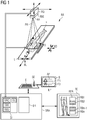
- FIG. 1 is a simplified X-ray system RA shown.
- This figure schematically shows a patient P placed on a couch L. From this patient P, for example, an X-ray panoramic photograph should be taken of the hip with the legs.
- an X-ray source RQ with an X-ray aperture unit RBE and below the couch a detector D is arranged above the couch L.
- a recording unit for example a camera KA, is fastened to the X-ray screen unit RBE.
- this arrangement is moved to the ceiling or floor-supported for applying an X-ray panoramic image RPA along the patient P as intended.
- the couch L can be moved with the patient P positioned on it.
- the directions of movement of the individual components are indicated.
- each with individual guide systems for the X-ray source RQ and the detector D these can be coordinated and the X-ray source RQ and the detector D are aligned with each other along the patient P procedure.
- Combined or corresponding movements between the X-ray source RQ, the detector D and the couch L are likewise possible in order to create an X-ray panoramic image RPA of the patient P.
- the respective positions of the X-ray source RQ, the detector D and the couch L and the patient P are known, inter alia, to the image computer BR for producing the overview image or the X-ray panorama image.
- the individual components depicted here such as the X-ray source RQ, X-ray diaphragm unit RBE, camera KA, detector D, couch L and patient P, are designed such that their positions in each X-ray image or partial X-ray image are forwarded to the X-ray system control unit SRA for an X-ray panorama recording.
- the image computer BR arranged in the X-ray system control unit SRA can access this position data.
- the orientation or the method of the individual components can be done with a control unit SE associated with an input unit E.
- a control unit SE associated with an input unit E.
- individual processor-controlled control units such as an X-ray control unit SRQ, an aperture control unit SBE, a detector control unit SBD and a couch control unit SL are arranged.
- the X-ray source RQ is coordinated with the other components of the X-ray system RA by means of an X-ray source control unit SRQ arranged in the X-ray system control unit SRA.
- the X-ray diaphragm unit RBE can be controlled via the diaphragm control unit SBE such that at least one first and / or second semitransparent X-ray diaphragm ERB, ZRB within the X-ray diaphragm unit RBE can be controlled such that, in accordance with the position of a partial X-ray image RB1,..., RBn within the X-ray panoramic image RPA, they can be moved into the X-ray cone RK emanating from the X-ray source RQ.
- An X-ray panorama recording RPA can, as in the Figures 3 or 2 shown, are combined with partial X-ray images RB1, ..., RBn using a uniform or different X-ray dose, especially in the overlapping areas.
- the creation of an X-ray panorama recording RPA can be menu-controlled, for example displayed on a screen B or via input aids of a touchscreen unit TE.
- a first boundary line AP for the beginning and a second boundary line EP for the end of the X-ray panoramic image RPA are input to a patient P shown schematically or by means of a video camera.
- so-called focus areas FB can be defined in which the respective partial X-ray image RBx is to be created with the best possible X-ray image quality.
- the image computer BR arranged in the X-ray system control unit SRA determines the number of partial X-ray images RB1,..., RBn between the first and second boundary lines AP, EP taking into account focal areas FB when using a selectable detector D of a specific size.
- the width of the possible overlapping areas UB of the edge regions of the partial radiographs RB1,..., RBn to be joined one above the other is likewise predefinable. It is then determined by input whether the X-ray panorama image RPA is to be created with a constant X-ray image quality or with a different X-ray image quality.
- a first and / or second semitransparent X-ray diaphragm ERB, ZRB is moved into the X-ray cone RK emanating from the X-ray source RBE, at least in the overlapping regions. If an X-ray panorama image RPA with different X-ray image quality is to be compiled, then a narrower overlapping region UB can be specified and this respectively by the first and / or second semitransparent X-ray diaphragm ERB, ZRB are covered.
- a large overlap region UB is predetermined and a semitransparent X-ray diaphragm ERB, ZRB covers, for example, only half of the respective overlapping region UB of the partial X-ray images RB1,..., RBn to be joined.
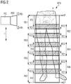
- FIG. 2 a first embodiment variant for applying an X-ray panorama recording RPA is shown.
- the X-ray source RQ is displaced along a trajectory T.
- the hip and the legs of the patient P are to be imaged with this X-ray panoramic image RDA.
- the beginning of the X-ray panorama image RDA is marked with a first boundary line AP at the upper edge of the hip and the end of the X-ray panorama image RDA with a second boundary line EP below the ankle.
- first boundary line AP at the upper edge of the hip
- EP second boundary line
- a first semitransparent collimator ERB and a second semitransparent collimator ZRB can be moved into the diaphragm aperture of the X-ray diaphragm unit RBE as required in the X-ray cone RK emitted by the X-ray source RQ. How far respectively the first and second semitransparent collimator ERB, ZRB are pushed or moved into the partial X-ray images RB1,... RBn to be applied can be predefined by specifying a first and a second overlapping area RD1, RD2 before X-ray panorama recording begins.
- the first semitransparent collimator ERB is moved in the X-ray aperture unit RBE into the X-ray cone emitted by the X-ray source RQ after predefining the size of a first overlapping region RD1.
- the X-ray source RQ is moved along the trajectory T.
- the second semitransparent collimator ZRB is moved into the opening of the X-ray diaphragm unit RBE.
- the second Partial radiograph RB2 begins where the first overlap region RD1 in the first partial radiograph RB1 begins.
- the second partial radiograph RB2 in contrast to the first partial radiograph RB1, has a first and a second overlapping region RD1, RD2. Within these first and second overlapping areas RD1, RD2, the X-ray dose of the X-rays directed onto the P inlaid P is reduced in accordance with the semitransparent X-ray apertures ERB, ZRB used.
- the width of the second overlapping area RD2 produced by the second semitransparent X-ray diaphragm ZRB in the second partial radiograph RB2 corresponds to the width of the first overlapping area RD1 recorded in the reduced X-ray dose in the first partial radiograph RB1.
- Subsequent partial radiographs RB3, .... RBn-1 are created accordingly.
- the region between the first and second transition regions RD1, RD2 in the partial X-ray images is in each case transilluminated with an X-ray dose optimized for the respective object segment.
- the creation of further overlapping partial X-ray images RBn for the X-ray panorama recording RPA is continued up to the second boundary line EP.
- the first semitransparent collimator ERB is moved out of the X-ray aperture unit RBE, since only one overlapping region to the preceding partial X-ray image RB6 is required.
- the overall picture results in an X-ray panorama image RPA, which could be arranged in a strip.
- This X-ray panorama image RPA then has regions with a high-contrast image between the respectively overlapping first and second overlapping regions RD1, RD2.
- the partial radiographs RB2, RB3, RB5 and RB6 in which neither hip joints, knees or ankles are shown can be applied with a lower X-ray dose.
- This compilation of the X-ray panoramic image RPA has the advantage that at least areas in the base of the leg, such as the socket joint in the pelvis, the knee and the ankle of the foot have been defined as focus areas FB and imaged with optimized X-radiation in the partial X-ray images RB1, RB4 and RB7 become.
- the intervening Long bones are of secondary importance for an assessment or determination of, for example, a leg axis. In these sections here, the patient P is only burdened by a reduced X-ray dose.
- FIG. 2 shows a further exemplary embodiment for combining first, second and third partial X-ray images RBn-1, RBn, RBn + 1 into an X-ray panoramic image RPA.
- this embodiment in contrast to the embodiment below Fig. 2 , In each case larger overlapping areas ÜB provided in the partial X-ray images.
- These overlapping regions UB between two partial X-ray images have at least the width of the first and / or second regions RD1, RD2 produced by the first and second X-ray apertures ERB, ZRB in the corresponding partial X-ray images.
- an adjacent X-ray partial image RBx-1 and / or RBn + 1 is added to an X-ray X-ray image RBx for an X-ray panoramic image RPA, then the overlapping regions UB are superimposed between the partial X-ray images RBx-1, RBx and RBx + 1.
- the overlapping area ÜB extends, for example approximately to the middle of the partial X-ray images.
- a section of a partial X-ray image with an object-related X-ray irradiation and an area of the partial X-ray image in which the X-ray radiation has been reduced by the use of a first or second semi-transparent X-ray aperture ERB, ZRB are superimposed.
- the overlapping area ÜB between the second and third partial radiographs RBn, RBn + 1 there is a section with optimized X-ray radiation from the second partial radiograph RBn with the second region RD2 from the third partial radiograph RBn + 1 and the first region RD1 from FIG second partial radiograph RBn with a portion of the third partial radiograph RBn + 1 on top of each other.
- An alignment of the second and third partial X-ray images RBn, RBn + 1 and an alignment of the first and second partial X-ray images RBn-1, RBn is carried out in each case by means of identical striking Points or surface structures in the overlapping areas ÜB.
- the areas which were recorded with a reduced X-ray dose are separated from the respective partial X-ray images and the remaining parts of the partial X-ray images RBn-1, RBn, RBn + 1 merge seamlessly together.
Landscapes
- Health & Medical Sciences (AREA)
- Life Sciences & Earth Sciences (AREA)
- Engineering & Computer Science (AREA)
- Medical Informatics (AREA)
- Physics & Mathematics (AREA)
- Pathology (AREA)
- Public Health (AREA)
- Biophysics (AREA)
- Nuclear Medicine, Radiotherapy & Molecular Imaging (AREA)
- Optics & Photonics (AREA)
- Veterinary Medicine (AREA)
- Radiology & Medical Imaging (AREA)
- Biomedical Technology (AREA)
- Heart & Thoracic Surgery (AREA)
- Molecular Biology (AREA)
- Surgery (AREA)
- Animal Behavior & Ethology (AREA)
- General Health & Medical Sciences (AREA)
- High Energy & Nuclear Physics (AREA)
- Computer Vision & Pattern Recognition (AREA)
- Human Computer Interaction (AREA)
- General Physics & Mathematics (AREA)
- Apparatus For Radiation Diagnosis (AREA)
Abstract
Description
- Die Erfindung bezieht sich auf eine Vorrichtung bzw. ein Verfahren zur Zusammensetzung einer aus mehreren Einzelröntgenbildern bestehenden Gesamt- bzw. Röntgenpanoramaaufnahme.
- Unterstützend für eine ärztliche Diagnose können z.B. Röntgenbilder angelegt werden. Mit den Röntgenbildern können unter anderem Gefäß- und Knochenstrukturen sowie Ausrichtungen der Wirbelsäule oder der Beine visualisiert werden. Lange Röhrenknochen, die gesamte Wirbelsäule oder auch die Abbildung eines Beines mit Hüftgelenk einschließlich des Oberschenkelknochens, des Knie- und des Sprunggelenks, z.B. zur Bestimmung einer Beinachse, sind mit einem einzelnen Röntgenbild, wegen einer die Röntgenbildgröße limitierenden Detektorgröße, nur sehr schwer bestimmbar. Um eine Gesamtbetrachtung z.B. der Wirbelsäule, eines Beines oder eines Armes zu erhalten, werden eine Vielzahl von aneinander zu reihenden Röntgenbildern, nachfolgend auch als Teilröntgenbilder bezeichnet, von dem zu betrachtenden Körperabschnitt angelegt. Zur Erstellung eines Gesamtbildes werden jeweils überlappende Bereiche bei den aneinander zu fügenden Teilröntgenbildern vorgesehen, um anhand von übereinstimmenden markanten Strukturen in den überlappenden Bereichen der angrenzenden Teilröntgenbilder aneinanderzufügen. Sind diese markanten Strukturen nur eingeschränkt vorhanden, so können mittels Korrelationsverfahren Übereinstimmungen errechnet und die angrenzenden Röntgenbilder zueinander ausgerichtet werden. Um beispielsweise Korrelationsverfahren erfolgreich durchzuführen, müssen aber geeignet große überlappende Bereiche vorhanden sein. Breite überlappende Bereiche bringen aber für den Patienten den Nachteil mit sich, dass er einer erhöhten Röntgendosis ausgesetzt ist. Darüber hinaus bedarf es aufwändiger zeitintensiver Rechenoperationen, um Übereinstimmungswahrscheinlichkeiten in überlappenden Bildanteilen zu ermitteln.
- Der Erfindung liegt die Aufgabe zugrunde, eine weitere Vorrichtung und ein dazugehöriges Verfahren zur Erstellung einer aus Teilröntgenbildern zusammen zu fügenden Röntgenpanoramaaufnahme anzugeben.
- Die der Erfindung zugrundeliegende Aufgabe wird durch die im Patentanspruch 1 oder 6 angegebenen Merkmale gelöst.
- Die Vorrichtung und das dazugehörige Verfahren weist eine Röntgenanlage zum Anlegen von Teilröntgenbildern für eine Röntgenpanoramaaufnahme auf. Diese Röntgenanlage ist mit einer Röntgenblendeneinheit mit einem ersten und/oder zweiten semitransparenten Kollimator ausgestattet. Der erste und/oder zweite semitransparente Kollimator kann beim Anlegen von Teilröntgenbildern für eine Röntgenpanoramaaufnahme derart angesteuert werden, dass die Kollimatoren in den von der Röntgenquelle ausgehenden Röntgenstrahlkegel derart gefahren werden, dass zumindest Teile der sich überlappenden Bereiche von den aneinanderzufügenden Teilröntgenbildern mit einer reduzierten Röntgendosis anlegbar sind.
- Die Erfindung bringt den Vorteil mit sich, dass die Röntgenstrahlenbelastung zur Erstellung einer Röntgenpanoramaaufnahme für den Patienten erheblich reduziert ist.
- Die Erfindung bringt den Vorteil mit sich, dass die Röntgenpanoramaaufnahme schnell, präzise und reproduzierbar erstellt werden kann.
- Die Erfindung bringt den Vorteil mit sich, dass die überlappenden Teile von aneinandergrenzenden Teilröntgenbildern mit einer erheblich reduzierten Röntgendosis und Bereiche mit hoher Aussagekraft mit einer hierfür optimierten Röntgendosis anlegbar sind.
- Die Erfindung bringt den Vorteil mit sich, dass die einzelnen Teilröntgenbilder ohne sichtbare Übergänge aneinanderfügbar sind.
- Die Erfindung bringt den Vorteil mit sich, dass das Ausrichten der einzelnen Teilröntgenbilder einer Röntgenpanoramaaufnahme anhand von Merkmalen in parallaxenfreien Bereichen in den einzelnen Teilröntgenbildern erfolgt.
- Vorteilhafte Ausgestaltungen der Erfindung sind in den Unteransprüchen angegeben.
- Die Erfindung soll im Folgenden mittels der in den Zeichnungen dargestellten Ausführungsbeispiele näher erläutert werden.
- Es zeigen:
- Figur 1
- eine schematische Anordnung einer Röntgenanlage,
- Figur 2
- das Entstehen einer ersten Röntgenpanoramaaufnahme und
- Figur 3
- das Entstehen einer zweiten Röntgenpanoramaaufnahme.
- Durch die Vorrichtung und das dazugehörige Verfahren wird bei der Erstellung einer Röntgenpanoramaaufnahme die Röntgenbelastung für den Patienten trotz größerer Überlappungsbereiche beim Anlegen von Teilröntgenbildern durch eine Verwendung von semitransparenten Röntgenblenden reduziert.
- In
Figur 1 ist eine Röntgenanlage RA vereinfacht abgebildet. Diese Abbildung zeigt schematisch einen auf einer Liege L platzierten Patienten P. Von diesem Patienten P soll beispielsweise eine Röntgenpanoramaaufnahme ab der Hüfte mit den Beinen erstellt werden. Oberhalb der Liege L ist eine Röntgenquelle RQ mit einer Röntgenblendeneinheit RBE sowie unterhalb der Liege ein Detektor D angeordnet. An der Röntgenblendeneinheit RBE ist eine Aufzeichnungseinheit, beispielsweise eine Kamera KA, befestigt. Im Falle einer starren Verbindung zwischen Röntgenquelle RQ und Detektor D wird diese Anordnung Decken- oder Bodengestützt zum Anlegen eines Röntgenpanoramabildes RPA entlang des Patienten P bestimmungsgemäß verfahren. Im Falle einer statischen Anordnung von Röntgenquelle RQ und Detektor D kann die Liege L mit dem auf ihr positionierten Patienten P verfahren werden. Die Bewegungsrichtungen der einzelnen Komponenten sind angedeutet. Bei selbständigen Systemen mit jeweils einzelnen Führungssystemen für die Röntgenquelle RQ und den Detektor D können diese aufeinander abgestimmt und die Röntgenquelle RQ und der Detektor D zueinander ausgerichtet entlang des Patienten P verfahren werden. Kombinierte bzw. korrespondierende Bewegungen zwischen Röntgenquelle RQ, Detektor D, Liege L sind ebenfalls möglich um eine Röntgenpanoramaaufnahme RPA vom Patienten P zu erstellen. Die jeweiligen Positionen von Röntgenquelle RQ, Detektor D und Liege L und Patient P sind u.a. dem Bildrechner BR zur Erstellung der Übersichtsaufnahme bzw. der Röntgenpanoramaaufnahme bekannt. Die einzelnen hier abgebildeten Komponenten wie Röntgenquelle RQ, Röntgenblendeneinheit RBE, Kamera KA, Detektor D, Liege L und Patient P sind so ausgebildet, das deren Positionen bei jedem Röntgenbild bzw. Teilröntgenbild für eine Röntgenpanoramaaufnahme an die Röntgenanlagensteuereinheit SRA weitergeleitet werden. Auf diese Positionsdaten kann der in der Röntgenanlagensteuereinheit SRA angeordnete Bildrechner BR zugreifen. Die Ausrichtung beziehungsweise das Verfahren der einzelnen Komponenten wie Röntgenquelle RQ, Detektor D, oder evtl. Liege L kann mit einer einer Eingabeeinheit E zugeordneten Steuereinheit SE erfolgen. In der Röntgenanlagensteuereinheit SRA sind u.a. einzelne prozessorgesteuerte Steuereinheiten wie eine Röntgensteuereinheit SRQ, eine Blendensteuereinheit SBE, eine Detektorsteuereinheit SBD und eine Liegensteuereinheit SL angeordnet. Die Röntgenquelle RQ wird über eine mit in der Röntgenanlagensteuereinheit SRA angeordneten Röntgenquellensteuereinheit SRQ mit den anderen Komponenten der Röntgenanlage RA koordinierend gesteuert. Die Röntgenblendeneinheit RBE kann über die Blendensteuereinheit SBE derart angesteuert werden, dass zumindest eine erste und/oder zweite semitransparente Röntgenblende ERB, ZRB innerhalb der Röntgenblendeneinheit RBE derart ansteuerbar ist, dass diese entsprechend der Position eines Teilröntgenbildes RB1, ...,RBn innerhalb der Röntgenpanoramaaufnahme RPA in den von der Röntgenquelle RQ ausgehenden Röntgenstrahlkegel RK fahrbar sind. Eine Röntgenpanoramaaufnahme RPA kann dabei, wie in denFiguren 3 oder2 dargestellt, mit Teilröntgenbildern RB1, ...,RBn unter Verwendung einer einheitlichen oder unterschiedlichen Röntgendosis, insbesondere in den sich überlappenden Bereichen, zusammengesetzt werden. Über die Eingabeeinheit E kann das Anlegen einer Röntgenpanoramaaufnahme RPA menügesteuert, beispielsweise angezeigt an einen Bildschirm B oder über Eingabehilfen einer Touchsreen-Einheit TE, erfolgen. Auf dem Bildschirm B oder der Touchsreen-Einheit TE wird an einen schematisch oder mittels Videocamera abgebildeten Patienten P eine erste Begrenzungslinie AP für den Beginn und eine zweite Begrenzungslinie EP für das Ende des Röntgenpanoramabildes RPA eingegeben. Zusätzlich sind sogenannte Fokusbereiche FB festlegbar in denen das jeweilige Teilröntgenbild RBx mit einer bestmöglichen Röntgenbildqualität erstellt werden soll. Der in der Röntgenanlagensteuereinheit SRA angeordnete Bildrechner BR ermittelt danach die Anzahl der Teilröntgenbilder RB1,..., RBn zwischen der ersten und zweiten Begrenzungslinie AP, EP unter Berücksichtigung von Fokusbereichen FB bei Verwendung eines wählbaren Detektors D bestimmter Größe. Die Breite der möglichen Überlappungsbereiche ÜB der übereinander zu fügenden Randbereiche der Teilröntgenbilder RB1,...,RBn ist ebenso vorgebbar. Danach wird durch Eingabe bestimmt, ob die Röntgenpanoramaaufnahme RPA mit einer gleichbleibenden Röntgenbildqualität oder mit unterschiedler Röntgenbildqualität erstellt werden soll. Um die Röntgenbelastung für den Patienten P signifikant zu reduzieren wird zumindest in den Überlappungsbereichen eine erste und/oder zweite semitransparente Röntgenblende ERB, ZRB in den von der Röntgenquelle RBE ausgehenden Röntgenstrahlkegel RK gefahren. Soll eine Röntgenpanoramaaufnahme RPA mit unterschiedlicher Röntgenbildqualität zusammengestellt werden, so kann ein schmälerer Überlappungsbereich ÜB vorgegeben und dieser jeweils durch die erste und/oder zweite semitransparente Röntgenblende ERB, ZRB abgedeckt werden. Soll eine Röntgenpanoramaaufnahme RPA mit gleichbleibender Röntgenbildqualität gebildet werden, so wird ein großer Überlappungsbereich ÜB vorgegeben und eine semitransparente Röntgenblende ERB, ZRB deckt beispielsweise nur die Hälfte des jeweiligen Überlappungsbereichs ÜB der aneinanderzufügenden Teilröntgenbilder RB1,...,RBn ab. - In
Figur 2 ist eine erste Ausführungsvariante zum Anlegen einer Röntgenpanoramaaufnahme RPA gezeigt. Die Röntgenquelle RQ wird entlang einer Trajektorie T verschoben. Mit dieser Röntgenpanoramaaufnahme RDA sollen die Hüfte und die Beine des Patienten P abgebildet werden. Der Beginn der Röntgenpanoramaaufnahme RDA wird mit einer ersten Begrenzungslinie AP am oberen Rand der Hüfte und das Ende der Röntgenpanoramaaufnahme RDA mit einer zweiten Begrenzungslinie EP unterhalb des Sprunggelenks markiert. Angedeutet ist hier der Übersichthalber nur die Röntgenquelle RQ und eine der Röntgenquelle RQ nachgeordnete Röntgenblendeneinheit RBE. Am Ausgang der Röntgenblendeneinheit RBE kann ein erster semitransparenter Kollimator ERB und ein zweiter semitransparenter Kollimator ZRB in die Blendenöffnung der Röntgenblendeneinheit RBE je nach Anforderung in den von der Röntgenquelle RQ abgegebenen Röntgenstrahlkegel RK gefahren werden. Wie weit jeweils der erste und zweite semitransparente Kollimator ERB, ZRB in die anzulegenden Teilröntgenbilder RB1,...RBn geschoben bzw. gefahren wird kann vor Beginn der Röntgenpanoramaaufnahme RPA durch Angabe eines ersten und zweiten Überlappungsbereichs RD1, RD2 vorgegeben werden. Wird beispielsweise mit einem den Hüftbereich des Patienten abbildenden Teilröntgenbild RB1 begonnen, so wird der erste semitransparente Kollimator ERB in der Röntgenblendeneinheit RBE nach Vorgabe der Größe eines ersten Überlappungsbereiches RD1 in den von der Röntgenquelle RQ abgegebenen Röntgenkegel gefahren. Für ein zweites Teilröntgenbild RB2 wird die Röntgenquelle RQ entlang der Trajektorie T entsprechend verfahren. Während des Verfahrens der Röntgenquelle RQ wird die zweite semitransparente Kollimator ZRB in die Öffnung der Röntgenblendeneinheit RBE gefahren. Das zweite Teilröntgenbild RB2 beginnt dort wo der erste Überlappungsbereich RD1 im ersten Teilröntgenbild RB1 beginnt. Das zweite Teilröntgenbild RB2 weist im Gegensatz zum ersten Teilröntgenbild RB1 einen ersten und zweiten Überlappungsbereich RD1, RD2 auf. Innerhalb dieser ersten und zweiten Überlappungsbereiche RD1, RD2 ist die Röntgendosis der auf den Pateinten P gerichteten Röntgenstrahlen entsprechend der verwendeten semitransparenten Röntgenblenden ERB, ZRB reduziert. Die Breite des durch die zweite semitransparente Röntgenblende ZRB erzeugten zweiten Überlappungsbereichs RD2 in dem zweiten Teilröntgenbild RB2 entspricht der Breite des mit reduzierter Röntgendosis aufgenommenen ersten Überlappungsbereich RD1 im ersten Teilröntgenbild RB1. Nachfolgende Teilröntgenbilder RB3,.... RBn-1 werden entsprechend angelegt. Der Bereich zwischen den ersten und zweiten Übergangsbereich RD1, RD2 in den Teilröntgenbildern wird jeweils mit einer auf den jeweiligen Objektabschnitt optimierten Röntgendosis durchleuchtet. Das Anlegen weiterer sich überlappender Teilröntgenbilder RBn für die Röntgenpanoramaaufnahme RPA wird bis zur zweiten Begrenzungslinie EP fortgesetzt. Bei dem letzten Teilröntgenbild RB7 für die Röntgenpanoramaaufnahme RPA wird jedoch der erste semitransparente Kollimator ERB aus der Röntgenblendeneinheit RBE gefahren, da nur noch ein Überlappungsbereich zum vorhergehenden Teilröntgenbild RB6 benötigt wird. Im Gesamtbild ergibt sich eine Röntgenpanoramaaufnahme RPA, das streifenförmig angelegt sein könnte. Diese Röntgenpanoramaaufnahme RPA weist dann Bereiche mit einer kontrastreichen Abbildung zwischen den sich jeweils überlappenden ersten und zweiten Überlappungsbereichen RD1, RD2 auf. Die Teilröntgenbilder RB2, RB3, RB5 sowie RB6 in denen weder Hüftgelenke, Knie oder Sprunggelenke abgebildet sind können mit einer geringeren Röntgendosis angelegt werden. Diese Zusammenstellung des Röntgenpanoramabildes RPA bringt den Vorteil mit sich, das zumindest Bereiche im Ansatz des Beines wie beispielsweise das Pfannengelenkt im Becken, das Knie und das Sprunggelenk des Fußes als Fokusbereiche FB definiert wurden und mit optimierter Röntgenstrahlung in den Teilröntgenbildern RB1, RB4 und RB7 abgebildet werden. Die dazwischenliegenden Röhrenknochen sind für eine Beurteilung oder Ermittlung beispielsweise einer Beinachse von nachgeordneter Bedeutung. In diesen Abschnitten hier wird der Patient P lediglich durch eine reduzierte Röntgendosis belastet. - In
Figur 3 ist ein weiteres Ausführungsbeispiel zur Zusammenfügung von einem ersten, zweiten und dritten Teilröntgenbild RBn-1, RBn, RBn+1 zu einer Röntgenpanoramaaufnahme RPA abgebildet. Bei dieser Ausführungsvariante werden, im Unterschied zu dem Ausführungsbeispiel unterFig. 2 , jeweils größere Überlappungsbereiche ÜB bei den Teilröntgenbildern vorgesehen. Diese Überlappungsbereiche ÜB zwischen zwei Teilröntgenbildern weisen mindestens die Breite der durch die ersten und zweiten Röntgenblenden ERB, ZRB erzeugten ersten und/oder zweiten Bereiche RD1, RD2 in den entsprechenden Teilröntgenbildern auf. Wird zu einem Teilröntgenbild RBx ein angrenzendes Teilröntgenbild RBx-1 und/oder RBn+1 zu einer Röntgenpanoramaaufnahme RPA angefügt, so werden die Überlappungsbereiche ÜB zwischen den Teilröntgenbildern RBx-1, RBx und RBx+1 übereinander gelegt. Bei einem Zusammenfügen von Teilröntgenbildern RB1, RB2; RP2, RP3; ...,RBn, RBn+1 reicht der Überlappungsbereich ÜB beispielsweise annähernd jeweils bis zur Mitte der Teilröntgenbilder. In den Überlappungsbereichen liegen jeweils ein Abschnitt eines Teilröntgenbildes mit einer objektbezogenen Röntgenbestrahlung und ein Bereich des Teilröntgenbildes in dem die Röntgenstrahlung durch die Verwendung von einer ersten oder zweiten semitransparenten Röntgenblende ERB, ZRB reduziert wurde übereinander. Betrachtet man beispielsweise den Überlappungsbereich ÜB zwischen dem zweiten und dritten Teilröntgenbild RBn, RBn+1, so liegen ein Abschnitt mit einer optimierten Röntgenbestrahlung aus dem zweiten Teilröntgenbild RBn mit dem zweiten Bereich RD2 aus dem dritten Teilröntgenbild RBn+1 sowie der erste Bereich RD1 aus dem zweiten Teilröntgenbild RBn mit einen Abschnitt des dritten Teilröntgenbildes RBn+1 übereinander. Eine Ausrichtung des zweiten und dritten Teilröntgenbildes RBn, RBn+1 sowie eine Ausrichtung des ersten und zweiten Teilröntgenbildes RBn-1, RBn erfolgt jeweils anhand von identischen markanten Punkten oder Flächenstrukturen in den Überlappungsbereichen ÜB. Nach Abschluss der Korrelation zwischen den jeweils angrenzenden Teilröntgenbildern RB1,...,RBn werden die Bereiche, die mit einer reduzierten Röntgendosis aufgenommen wurden, von den jeweiligen Teilröntgenbildern getrennt und die verbleibenden Teile der Teilröntgenbilder RBn-1, RBn, RBn+1 übergangslos aneinander gefügt. - In einer weiteren Ausführungsvariante kann jeweils nur ein Randbereich pro Teilröntgenbild, beispielsweise ein Bereich der durch eine erste Röntgenblende ERB mit einer reduzierten Röntgendosis RD1 aufgenommen wurde, mit einem Randbereich eines angrenzenden Teilröntgenbildes überlagert werden.
-
- T
- Trajektorie
- RA
- Röntgenanlage
- KA
- Kamera
- RQ
- Röntgenquelle
- RK
- Röntgenstrahlkegel
- RBE
- Röntgenblendeneinheit
- D
- Detektoreinheit
- L
- Liege
- P
- Patient
- BD
- Bewegungsrichtung Detektor
- BL
- Bewegungsrichtung der Liege
- SRA
- Röntgenanlagensteuereinheit
- S
- Steuereinheit
- SL
- Liegensteuereinheit
- SRQ
- Röntgenquellensteuereinheit
- SBE
- Röntgenblendensteuereinheit
- SBD
- Detektorsteuereinheit
- BR
- Bildrechner
- SE
- Joystick
- E
- Eingabeeinheit
- TE
- Touchscreen-Einheit
- RB1,...,RBn
- erstes, ..., n-tes Teilröntgenbild (RBn-x,..., RBn,..., RBn+y)
- ERB
- erste semitransparente Röntgenblende/Kollimator
- ZRB
- zweite semitransparente Röntgenblende/Kollimator
- DA1, ..., DAx
- Detektorabbildungen
- RPA
- Röntgenpanoramaaufnahme
- ÜB
- Überlappungsbereich
- B
- Bildschirmeinheit
- AP
- erste Begrenzungslinie
- EP
- zweite Begrenzungslinie
- FB
- Fokusbereiche
- RD1
- erster Überlappungsbereich
- RD2
- zweiter Überlappungsbereich
Claims (10)
- Vorrichtung mit einer eine Röntgenblendeneinheit (RBE) aufweisenden Röntgenquelle (RQ) und einem Detektor (D) zum Anlegen von Teilröntgenbildern (RBn-x,...,RBn,...,RBn+y)
dadurch gekennzeichnet,
dass die einen ersten und/oder zweiten semitransparenten Kollimator (ERB, ZRB) aufweisende Röntgenblendeneinheit (RBE) beim Anlegen von Teilröntgenbildern (RBn-x,...,RBn,...,RBn+y) einer Röntgenpanoramaaufnahme (RPA) derart ansteuerbar ist, dass beim Anlegen von Teilröntgenbildern (RBn-x,...,RBn,..., RBn+y) für eine Röntgenpanoramaaufnahme (RPA) der erste und/oder zweite semitransparente Kollimator (ERB, ZRB) in den von der Röntgenquelle (RQ) ausgehenden Röntgenstrahlkegel (RK) derart verfahren werden, dass zumindest Teile der sich überlappenden Bereiche von aneinanderzufügenden Teilröntgenbildern (RBn-x,..., RBn, ...,RBn+y) mit einer reduzierten Röntgendosis anlegbar sind. - Vorrichtung nach Patentanspruch 1,
dadurch gekennzeichnet,
dass eine Eingabeeinheit (E, B, TE) vorgesehen ist mit der eine erste Begrenzungslinie (AP) und eine zweite Begrenzungslinie (EP) an einem auf einem Bildschirmelement (B, TE) abgebildeten Patienten (P) markierbar sind. - Vorrichtung nach Patentanspruch 2,
dadurch gekennzeichnet,
dass mindestens ein Fokusbereich (FB) vorgebbar ist. - Vorrichtung nach einem der vorhergehenden Patentansprüche,
dadurch gekennzeichnet,
dass die Breite eines Überlappungsbreichs (ÜB) zwischen zwei angrenzenden Teilröntgenbildern (RBn-1,RBn; RBn,RBn+1) vorgebbar ist. - Vorrichtung nach einem der vorhergehenden Patentansprüche,
dadurch gekennzeichnet,
dass diese einen Bildrechner (BR) aufweist, wobei die Aufteilung der Teilröntgenbilder (RBn-x,...,RBn,...,RBn+y) für eine Röntgenpanoramaaufnahme (RPA) anhand einer den Patienten (P) aufzeichnenden Kamera (KA) angebbar ist. - Verfahren für einer eine Röntgenblendeneinheit (RBE) aufweisenden Röntgenquelle (RQ) und einem Detektor (D) zum Anlegen von Teilröntgenbildern (RBn-1, RBn, ...,RBn+1)
dadurch gekennzeichnet,
dass beim Anlegen von Teilröntgenbildern (RBn-1, RBn, ..., RBn+1) für eine Röntgenpanoramaaufnahme (RPA) ein erster und/oder zweiter semitransparenter Kollimator (ERB, ZRB) in den von der Röntgenquelle (RQ) ausgehenden Röntgenstrahlkegel (RK) derart verfahren wird, dass zumindest Teile der sich überlappenden Bereiche von aneinanderzufügenden Teilröntgenbildern (RBn-1, RBn, ...,RBn+1) mit einer reduzierten Röntgendosis anlegt werden. - Verfahren nach Patentanspruch 6,
dadurch gekennzeichnet,
dass eine erste Begrenzungslinie (AP) und eine zweite Begrenzungslinie (EP) an einem auf einem Bildschirmelement (B, TE) abgebildeten Patienten (P) markierbar sind. - Verfahren nach einem der vorhergehenden Patentansprüche,
dadurch gekennzeichnet,
dass mindestens ein Fokusbereich (FB) angegeben wird. - Verfahren nach einem der vorhergehenden Patentansprüche,
dadurch gekennzeichnet,
dass die Breite der Überlappungsbereiche (ÜB) zwischen zwei angrenzenden Teilröntgenbildern (RBn-1,RBn; RBn,RBn+1) vorgegeben wird. - Verfahren nach einem der vorhergehenden Patentansprüche,
dadurch gekennzeichnet,
dass die Aufteilung der Teilröntgenbilder (RBn-x,...,RBn,...,RBn+y) für eine Röntgenpanoramaaufnahme (RPA) anhand einer den Patienten (P) aufzeichnenden Kamera (KA) angelegt wird.
Applications Claiming Priority (1)
| Application Number | Priority Date | Filing Date | Title |
|---|---|---|---|
| DE102016205176.8A DE102016205176A1 (de) | 2016-03-30 | 2016-03-30 | Vorrichtung und Verfahren zur Erstellung einer Röntgenpanoramaaufnahme |
Publications (2)
| Publication Number | Publication Date |
|---|---|
| EP3228250A1 true EP3228250A1 (de) | 2017-10-11 |
| EP3228250B1 EP3228250B1 (de) | 2021-08-25 |
Family
ID=58358417
Family Applications (1)
| Application Number | Title | Priority Date | Filing Date |
|---|---|---|---|
| EP17161235.1A Active EP3228250B1 (de) | 2016-03-30 | 2017-03-16 | Vorrichtung und verfahren zur erstellung einer röntgenpanoramaaufnahme |
Country Status (4)
| Country | Link |
|---|---|
| US (1) | US10925569B2 (de) |
| EP (1) | EP3228250B1 (de) |
| CN (1) | CN107272321B (de) |
| DE (1) | DE102016205176A1 (de) |
Families Citing this family (9)
| Publication number | Priority date | Publication date | Assignee | Title |
|---|---|---|---|---|
| EP3473185B1 (de) * | 2017-10-19 | 2022-06-22 | Siemens Healthcare GmbH | Tomosyntheseverfahren und röntgenaufnahmevorrichtung |
| DE102018212389B3 (de) * | 2018-07-25 | 2020-01-02 | Siemens Healthcare Gmbh | Verfahren zum Betrieb einer Röntgeneinrichtung, Röntgeneinrichtung, Computerprogramm und elektronisch lesbares Speichermedium |
| DE102020200959A1 (de) | 2019-02-25 | 2020-08-27 | Siemens Healthcare Gmbh | Aufnahme eines Panoramadatensatzes eines Untersuchungsobjektes mittels eines beweglichen medizinischen Röntgengerätes |
| JP7350519B2 (ja) * | 2019-05-29 | 2023-09-26 | キヤノン株式会社 | 放射線撮影システム、放射線撮影制御装置及びその制御方法、並びに、プログラム |
| DE102020209714A1 (de) | 2020-07-31 | 2022-02-03 | Siemens Healthcare Gmbh | Verfahren zur abschnittsweisen Aufnahme einer Röntgenaufnahme |
| DE102020212294B4 (de) | 2020-09-29 | 2022-10-06 | Siemens Healthcare Gmbh | Verfahren zur Aufnahme eines Bilddatensatzes |
| US20220280125A1 (en) * | 2021-03-02 | 2022-09-08 | Carestream Health, Inc. | X-ray bed |
| CN114587398B (zh) * | 2022-03-16 | 2023-07-04 | 中核高能(天津)装备有限公司 | 用于单光子发射断层成像的装置及投影数据的处理方法 |
| JP2024115138A (ja) * | 2023-02-14 | 2024-08-26 | 富士フイルムヘルスケア株式会社 | 医用画像撮像装置及びその制御方法 |
Citations (3)
| Publication number | Priority date | Publication date | Assignee | Title |
|---|---|---|---|---|
| WO1996015722A1 (en) * | 1994-11-23 | 1996-05-30 | Thermotrex Corporation | X-ray imaging device |
| EP1484016A1 (de) * | 2003-06-03 | 2004-12-08 | GE Medical Systems Global Technology Company LLC | Verfahren und Gerät zur Akquisition eines zusammengesetzten Bildes mit einem digitalen Detektor |
| US20140219420A1 (en) * | 2012-10-01 | 2014-08-07 | Kabushiki Kaisha Toshiba | X-ray diagnostic apparatus and method for controlling the same |
Family Cites Families (88)
| Publication number | Priority date | Publication date | Assignee | Title |
|---|---|---|---|---|
| DE2615335C3 (de) * | 1976-04-08 | 1985-07-18 | Siemens AG, 1000 Berlin und 8000 München | Primärstrahlenblende |
| DE3500812A1 (de) * | 1985-01-11 | 1986-07-17 | Siemens AG, 1000 Berlin und 8000 München | Roentgendiagnostikeinrichtung mit halbtransparenter blende |
| DE3621868A1 (de) * | 1986-06-30 | 1988-01-14 | Siemens Ag | Roentgendiagnostikeinrichtung mit einer blende |
| DE8711572U1 (de) * | 1987-08-26 | 1988-12-22 | Siemens AG, 1000 Berlin und 8000 München | Primärstrahlenblende für Röntgendiagnostikgeräte |
| EP0411189B1 (de) * | 1989-08-03 | 1993-05-26 | Siemens Aktiengesellschaft | Röntgendiagnostikeinrichtung |
| US5107529A (en) * | 1990-10-03 | 1992-04-21 | Thomas Jefferson University | Radiographic equalization apparatus and method |
| DE59100908D1 (de) * | 1991-03-01 | 1994-03-03 | Siemens Ag | Röntgendiagnostikeinrichtung mit einer Primärstrahlenblende. |
| US5278887A (en) | 1992-06-29 | 1994-01-11 | Siemens Corporate Research, Inc. | Apparatus and method for reducing X-ray dosage during a fluoroscopic procedure |
| US5282254A (en) * | 1992-06-29 | 1994-01-25 | Siemens Corporate Research, Inc. | Method for locating an edge portion of an aperture in a filter member in X-ray fluoroscopy apparatus |
| US5369678A (en) * | 1992-06-29 | 1994-11-29 | Siemens Corporate Research, Inc. | Method for tracking a catheter probe during a fluoroscopic procedure |
| CA2189468A1 (en) * | 1996-11-01 | 1998-05-01 | Jean A. Vezina | Device with a three-dimensional compensating filter for a gantry mounting radiography apparatus |
| DE19705035C1 (de) * | 1997-02-10 | 1998-05-07 | Siemens Ag | Verfahren zum Betrieb einer medizinischen Röntgendiagnostikeinrichtung und Röntgendiagnostikeinrichtung zur Durchführung des Verfahrens |
| DE19729414A1 (de) * | 1997-07-09 | 1999-02-11 | Siemens Ag | Strahlenblende eines medizinischen Gerätes |
| US6101238A (en) * | 1998-11-25 | 2000-08-08 | Siemens Corporate Research, Inc. | System for generating a compound x-ray image for diagnosis |
| EP1062913A1 (de) * | 1999-06-25 | 2000-12-27 | DDI Direct Digital Imaging GmbH | Röntgen-Bilderzeugung mittels Photographie und digitaler Abtastung |
| US6463121B1 (en) * | 1999-10-13 | 2002-10-08 | General Electric Company | Interactive x-ray position and exposure control using image data as reference information |
| DE19950794A1 (de) * | 1999-10-21 | 2001-06-13 | Siemens Ag | Röntgeneinrichtung und Verfahren zur Beeinflussung von Röntgenstrahlung |
| DE19962281A1 (de) * | 1999-12-23 | 2001-06-28 | Philips Corp Intellectual Pty | Röntgenuntersuchungsgerät |
| US6330299B1 (en) * | 2000-06-10 | 2001-12-11 | Ge Medical Systems Global Technology Company, Llc | System and method for determining dose area product in an X-ray imaging system |
| DE10048775B4 (de) * | 2000-09-29 | 2006-02-02 | Siemens Ag | Röntgen-Computertomographieeinrichtung |
| DE10160611A1 (de) * | 2001-12-11 | 2003-06-26 | Siemens Ag | Bildgebende medizinische Untersuchungseinrichtung |
| DE10232676B4 (de) * | 2002-07-18 | 2006-01-19 | Siemens Ag | Verfahren und Vorrichtung zur Positionierung eines Patienten in einem medizinischen Diagnose- oder Therapiegerät |
| JP2006517439A (ja) * | 2003-02-11 | 2006-07-27 | コーニンクレッカ フィリップス エレクトロニクス エヌ ヴィ | コリメータを持つx線装置及びコリメータを設定する方法 |
| DE10320862B4 (de) * | 2003-05-09 | 2007-09-06 | Siemens Ag | Verfahren zur automatischen Einstellung einer Blende, sowie Röntgensystem |
| US7340033B2 (en) * | 2003-07-30 | 2008-03-04 | Koninklijke Philips Electronics, N.V. | X-ray unit having an automatically adjustable collimator |
| JP3909059B2 (ja) * | 2004-01-07 | 2007-04-25 | ジーイー・メディカル・システムズ・グローバル・テクノロジー・カンパニー・エルエルシー | 放射線断層撮像装置およびそれを用いた撮像方法 |
| US7272208B2 (en) * | 2004-09-21 | 2007-09-18 | Ge Medical Systems Global Technology Company, Llc | System and method for an adaptive morphology x-ray beam in an x-ray system |
| US7522701B2 (en) * | 2005-12-20 | 2009-04-21 | General Electric Company | System and method for image composition using position sensors |
| JP5038031B2 (ja) | 2006-07-11 | 2012-10-03 | キヤノン株式会社 | 放射線撮影装置、その駆動方法及び放射線撮影システム |
| US7869637B2 (en) * | 2006-07-31 | 2011-01-11 | Siemens Medical Solutions Usa, Inc. | Histogram calculation for auto-windowing of collimated X-ray image |
| US7344305B2 (en) * | 2006-08-01 | 2008-03-18 | Siemens Medical Solutions Usa, Inc. | Remote visual feedback of collimated area and snapshot of exposed patient area |
| JP4942024B2 (ja) * | 2006-08-09 | 2012-05-30 | 富士フイルム株式会社 | 医用画像撮影方法及び医用画像撮影装置 |
| JP4986771B2 (ja) | 2006-08-31 | 2012-07-25 | キヤノン株式会社 | 撮像装置、その駆動方法及び放射線撮像システム |
| JP5586822B2 (ja) | 2006-10-18 | 2014-09-10 | キヤノン株式会社 | デジタル放射線検出器の保持装置、デジタル放射線検出器、デジタル放射線撮影装置、cアーム撮影装置、及び制御方法 |
| DE102007002417B4 (de) * | 2007-01-17 | 2018-02-22 | Siemens Healthcare Gmbh | Verfahren zur Bestimmung einer Position für wenigstens eine halbtransparente Blende und zugehörige Einrichtung |
| US7889841B2 (en) * | 2008-03-18 | 2011-02-15 | Siemens Medical Solutions Usa, Inc. | X-ray imaging system for performing automated multi-step imaging of patient anatomy |
| EP2310839A4 (de) * | 2008-06-18 | 2011-08-03 | Surgix Ltd | Verfahren und system zum zusammenfügen mehrerer bilder zu einem panoramabild |
| WO2010092516A1 (en) * | 2009-02-10 | 2010-08-19 | Koninklijke Philips Electronics N.V. | Medical viewing system for displaying an x-ray image |
| JP5612079B2 (ja) * | 2009-05-05 | 2014-10-22 | コーニンクレッカ フィリップス エヌ ヴェ | X線画像を取得する方法及び自動的なウェッジの位置決めを有するx線画像取得装置 |
| US8605861B2 (en) * | 2009-06-05 | 2013-12-10 | Siemens Medical Solutions Usa, Inc. | System for medical image display and image filter selection |
| JP5479069B2 (ja) * | 2009-12-17 | 2014-04-23 | 株式会社東芝 | X線ct装置及びx線ct装置の制御方法 |
| US8971493B2 (en) * | 2010-09-08 | 2015-03-03 | Siemens Medical Solutions Usa, Inc. | System for image scanning and acquisition with low-dose radiation |
| DE102011076371A1 (de) * | 2011-05-24 | 2012-11-29 | Siemens Aktiengesellschaft | Verfahren zum Gewinnen von Bilddaten mithilfe einer Röntgenbildaufnahmevorrichtung mit Filter sowie Röntgenbildaufnahmevorrichtung |
| US9121809B2 (en) * | 2011-11-18 | 2015-09-01 | Visuum, Llc | Multi-linear X-ray scanning systems and methods for X-ray scanning |
| US20130272504A1 (en) | 2012-04-16 | 2013-10-17 | Meir Deutsch | X-Ray Dose Reduction by Controlled Shutter Speed |
| KR101431781B1 (ko) * | 2012-06-20 | 2014-08-20 | 삼성전자주식회사 | 엑스선 영상 장치 및 그 제어방법 |
| WO2014054417A1 (ja) * | 2012-10-02 | 2014-04-10 | 株式会社島津製作所 | X線撮影装置 |
| KR101390190B1 (ko) * | 2012-10-11 | 2014-04-29 | 삼성전자주식회사 | X선 촬영장치 및 이를 이용한 촬영방법 및 x선 영상 획득 방법 |
| US9861329B2 (en) * | 2012-10-11 | 2018-01-09 | Samsung Electronics Co., Ltd. | X-ray apparatus and method of capturing X-ray image |
| US9259200B2 (en) * | 2012-10-18 | 2016-02-16 | Siemens Aktiengesellschaft | Method and system for obtaining a sequence of x-ray images using a reduced dose of ionizing radiation |
| DE102012219051A1 (de) * | 2012-10-18 | 2014-04-24 | Klinikum Der Universität München | Auswahl eines Strahlungsformfilters |
| CN105101877A (zh) * | 2012-11-29 | 2015-11-25 | 控制辐射系统有限公司 | X射线减少系统 |
| WO2014106783A1 (en) * | 2013-01-01 | 2014-07-10 | Controlrad Systems Inc. | X-ray reduction system |
| US9610053B2 (en) * | 2013-01-08 | 2017-04-04 | Shimadzu Corporation | Radiographic device |
| US9814435B2 (en) * | 2014-08-28 | 2017-11-14 | Samsung Electronics Co., Ltd. | Medical imaging apparatus and method of operating same |
| US10098598B2 (en) * | 2013-06-13 | 2018-10-16 | Samsung Electronics Co., Ltd. | X-ray imaging apparatus and method for controlling the same |
| WO2015019232A2 (en) * | 2013-08-08 | 2015-02-12 | Controlrad Systems Inc. | X-ray reduction system |
| JP6266284B2 (ja) * | 2013-09-19 | 2018-01-24 | 東芝メディカルシステムズ株式会社 | X線診断装置 |
| CN106030264B (zh) * | 2013-12-11 | 2021-01-15 | 控制辐射系统有限公司 | X射线减少系统 |
| DE102014202330B3 (de) * | 2014-02-10 | 2015-06-03 | Siemens Aktiengesellschaft | Single Source DualEnergy mit zwei Filtern zur Röntgenspektrumsdifferenzierung bei Strahlerblenden mit Schlitzplatte |
| DE102014203465B4 (de) * | 2014-02-26 | 2026-05-07 | Siemens Healthineers Ag | Auswahl eines Strahlungsformfilters aus einer Mehrzahl von Strahlungsformfiltern |
| JP6208600B2 (ja) * | 2014-03-03 | 2017-10-04 | 富士フイルム株式会社 | 放射線画像撮影装置および放射線画像撮影システム |
| US10582901B2 (en) * | 2014-04-24 | 2020-03-10 | Koninklijke Philips N.V. | Recognizer of staff or patient body parts using markers to prevent or reduce unwanted irradiation |
| US10667767B2 (en) * | 2014-05-02 | 2020-06-02 | General Electric Company | Systems and methods for selecting bowtie filter configuration |
| TWI535421B (zh) * | 2014-05-14 | 2016-06-01 | Automatic identification and adjustment of the selected parts of the medical equipment | |
| JP6184916B2 (ja) * | 2014-07-31 | 2017-08-23 | 富士フイルム株式会社 | 放射線画像撮影システム |
| US9375192B2 (en) * | 2014-10-14 | 2016-06-28 | Carestream Health, Inc. | Reconstruction of a cone beam scanned object |
| KR20160057816A (ko) * | 2014-11-14 | 2016-05-24 | 삼성전자주식회사 | 엑스선 장치와 콜리메이터. |
| EP3023057B1 (de) * | 2014-11-19 | 2021-03-31 | Fujifilm Corp | Strahlungsbildgebungsvorrichtung |
| CN107106111A (zh) * | 2015-01-23 | 2017-08-29 | 株式会社日立制作所 | X射线ct装置以及拍摄方法 |
| JP6072096B2 (ja) * | 2015-01-30 | 2017-02-01 | キヤノン株式会社 | 放射線撮影システム、制御方法、制御方法、及びプログラム |
| CN105832353B (zh) * | 2015-01-30 | 2020-11-06 | 佳能株式会社 | 放射线摄像系统 |
| JP6072100B2 (ja) * | 2015-01-30 | 2017-02-01 | キヤノン株式会社 | 放射線撮影システム、制御方法、制御方法、及びプログラム |
| US9936926B2 (en) * | 2015-02-02 | 2018-04-10 | Palodex Group Oy | System and method of small field of view X-ray imaging |
| JP2016179097A (ja) * | 2015-03-24 | 2016-10-13 | キヤノン株式会社 | 放射線撮像システム及び放射線撮影システム |
| JP6611449B2 (ja) * | 2015-03-31 | 2019-11-27 | キヤノン株式会社 | 放射線撮像システム及び放射線撮影システム |
| JP6525680B2 (ja) * | 2015-03-31 | 2019-06-05 | キヤノン株式会社 | 放射線撮影システム、制御方法およびプログラム |
| JP6443195B2 (ja) * | 2015-04-14 | 2018-12-26 | コニカミノルタ株式会社 | 放射線画像撮影システム |
| JP2016202252A (ja) * | 2015-04-15 | 2016-12-08 | キヤノン株式会社 | 放射線撮影システム、放射線撮影システムの制御方法およびプログラム |
| KR102126510B1 (ko) * | 2015-04-22 | 2020-06-24 | 삼성전자주식회사 | 엑스선 장치 및 시스템 |
| WO2017027452A1 (en) * | 2015-08-07 | 2017-02-16 | The United States of America, as represented by the Secretary, Deparment of Health and Human Services | Adaptive x-ray filter using spatial exposure time modulation with dynamic collimators |
| US10702229B2 (en) * | 2015-08-25 | 2020-07-07 | Samsung Electronics Co., Ltd. | X-ray imaging apparatus and method for controlling the same |
| DE102015217421B4 (de) * | 2015-09-11 | 2023-05-17 | Siemens Healthcare Gmbh | Spektrale Filterung von Röntgenstrahlung für energieselektive Röntgenbildgebung |
| DE102015221638B4 (de) * | 2015-11-04 | 2018-09-06 | Siemens Healthcare Gmbh | Verfahren zur Anpassung wenigstens eines Strahlungsparameters in einer Röntgeneinrichtung |
| KR20170060698A (ko) * | 2015-11-25 | 2017-06-02 | 삼성전자주식회사 | 컴퓨터 단층 촬영장치 및 그 제어방법 |
| CN105433973B (zh) * | 2015-12-30 | 2018-09-18 | 沈阳东软医疗系统有限公司 | Ct扫描设备、ct系统和控制过滤器组件的方法及装置 |
| DE102016204870B4 (de) * | 2016-03-23 | 2023-11-23 | Siemens Healthcare Gmbh | Blendenvorrichtung zur Kollimation eines Röntgenstrahlenbündels einer Röntgeneinrichtung |
| US10540764B2 (en) * | 2016-05-09 | 2020-01-21 | Canon Medical Systems Corporation | Medical image capturing apparatus and method |
-
2016
- 2016-03-30 DE DE102016205176.8A patent/DE102016205176A1/de not_active Withdrawn
-
2017
- 2017-03-16 EP EP17161235.1A patent/EP3228250B1/de active Active
- 2017-03-30 CN CN201710201764.0A patent/CN107272321B/zh active Active
- 2017-03-30 US US15/473,919 patent/US10925569B2/en active Active
Patent Citations (3)
| Publication number | Priority date | Publication date | Assignee | Title |
|---|---|---|---|---|
| WO1996015722A1 (en) * | 1994-11-23 | 1996-05-30 | Thermotrex Corporation | X-ray imaging device |
| EP1484016A1 (de) * | 2003-06-03 | 2004-12-08 | GE Medical Systems Global Technology Company LLC | Verfahren und Gerät zur Akquisition eines zusammengesetzten Bildes mit einem digitalen Detektor |
| US20140219420A1 (en) * | 2012-10-01 | 2014-08-07 | Kabushiki Kaisha Toshiba | X-ray diagnostic apparatus and method for controlling the same |
Also Published As
| Publication number | Publication date |
|---|---|
| CN107272321A (zh) | 2017-10-20 |
| DE102016205176A1 (de) | 2017-10-05 |
| CN107272321B (zh) | 2020-06-23 |
| EP3228250B1 (de) | 2021-08-25 |
| US10925569B2 (en) | 2021-02-23 |
| US20170281109A1 (en) | 2017-10-05 |
Similar Documents
| Publication | Publication Date | Title |
|---|---|---|
| EP3228250B1 (de) | Vorrichtung und verfahren zur erstellung einer röntgenpanoramaaufnahme | |
| DE10114099B4 (de) | Verfahren zum Detektieren der dreidimensionalen Position eines in einen Körperbereich eingeführten medizinischen Untersuchungsinstruments, insbesondere eines in ein Gefäß eingeführten Katheters | |
| DE102010020781B4 (de) | Bestimmung und Überprüfung der Koordinatentransformation zwischen einem Röntgensystem und einem Operationsnavigationssystem | |
| DE102011005777B4 (de) | Angiographiesystem zur angiographischen Untersuchung eines Patienten und angiographisches Untersuchungsverfahren | |
| DE102018212389B3 (de) | Verfahren zum Betrieb einer Röntgeneinrichtung, Röntgeneinrichtung, Computerprogramm und elektronisch lesbares Speichermedium | |
| DE102014219667B3 (de) | Verfahren zur Auswahl eines Aufnahmebereiches und System zur Auswahl eines Aufnahmebereichs | |
| DE10136160A1 (de) | Verfahren und Vorrichtung zur Registrierung zweier 3D-Bilddatensätze | |
| EP3210537B1 (de) | Erstellung eines dreidimensionalen abbilds eines körperteils durch ein röntgengerät | |
| DE102015201070A1 (de) | Röntgenaufnahmesystem | |
| DE10232676A1 (de) | Verfahren und Vorrichtung zur Positionierung eines Patienten in einem medizinischen Diagnose- oder Therapiegerät | |
| WO2015128108A1 (de) | Einstellen einer röntgenstrahlungseinheit | |
| DE102019214302B4 (de) | Verfahren zum Registrieren eines Röntgenbilddatensatzes mit einem Navigationssystem, Computerprogrammprodukt und System | |
| DE112008002137T5 (de) | Fluoroskop | |
| DE102005030285A1 (de) | Computertomographiegerät und Verfahren für ein Computertomographiegerät mit einem Markierungsmittel zur positionsgenauen Markierung einer Interventionsposition mittels eines Laser-strahls auf einem zu untersuchenden Objekt | |
| DE102014219666A1 (de) | Verfahren zur automatischen Patientenpositionierung sowie bildgebendes System | |
| DE102009016482B4 (de) | Vorrichtungen zur Unterstützung der Platzierung eines Implantats | |
| DE102006021372B4 (de) | Verfahren zur Erstellung eines dreidimensionalen Bilddatensatzes eines Zielvolumens und medizinische Untersuchungseinrichtung | |
| DE102007002417A1 (de) | Verfahren zur Bestimmung einer Position für wenigstens eine halbtransparente Blende und zugehörige Einrichtung | |
| DE102013209769B4 (de) | Röntgenbildgebungsgerät zum Stitching und zugehöriges Verfahren | |
| EP3499461B1 (de) | Darstellung von markern in der medizinischen bildgebung | |
| DE102008025946B3 (de) | Verfahren zur Aufnahme eines Röntgenbildes | |
| DE102004040629B4 (de) | Einstellen einer Relativposition einer Bestrahlungseinrichtung und eines Patienten | |
| DE102017212553B4 (de) | Synchrone MR-Bildgebung und Strahlentherapie | |
| EP3021756B1 (de) | Verfahren zur durchführung einer dreidimensionalen röntgenaufnahme | |
| DE112017001457T5 (de) | Medizinische bildausrichtung |
Legal Events
| Date | Code | Title | Description |
|---|---|---|---|
| PUAI | Public reference made under article 153(3) epc to a published international application that has entered the european phase |
Free format text: ORIGINAL CODE: 0009012 |
|
| STAA | Information on the status of an ep patent application or granted ep patent |
Free format text: STATUS: THE APPLICATION HAS BEEN PUBLISHED |
|
| AK | Designated contracting states |
Kind code of ref document: A1 Designated state(s): AL AT BE BG CH CY CZ DE DK EE ES FI FR GB GR HR HU IE IS IT LI LT LU LV MC MK MT NL NO PL PT RO RS SE SI SK SM TR |
|
| AX | Request for extension of the european patent |
Extension state: BA ME |
|
| STAA | Information on the status of an ep patent application or granted ep patent |
Free format text: STATUS: REQUEST FOR EXAMINATION WAS MADE |
|
| 17P | Request for examination filed |
Effective date: 20171106 |
|
| RBV | Designated contracting states (corrected) |
Designated state(s): AL AT BE BG CH CY CZ DE DK EE ES FI FR GB GR HR HU IE IS IT LI LT LU LV MC MK MT NL NO PL PT RO RS SE SI SK SM TR |
|
| GRAP | Despatch of communication of intention to grant a patent |
Free format text: ORIGINAL CODE: EPIDOSNIGR1 |
|
| STAA | Information on the status of an ep patent application or granted ep patent |
Free format text: STATUS: GRANT OF PATENT IS INTENDED |
|
| INTG | Intention to grant announced |
Effective date: 20210407 |
|
| GRAS | Grant fee paid |
Free format text: ORIGINAL CODE: EPIDOSNIGR3 |
|
| GRAA | (expected) grant |
Free format text: ORIGINAL CODE: 0009210 |
|
| STAA | Information on the status of an ep patent application or granted ep patent |
Free format text: STATUS: THE PATENT HAS BEEN GRANTED |
|
| AK | Designated contracting states |
Kind code of ref document: B1 Designated state(s): AL AT BE BG CH CY CZ DE DK EE ES FI FR GB GR HR HU IE IS IT LI LT LU LV MC MK MT NL NO PL PT RO RS SE SI SK SM TR |
|
| REG | Reference to a national code |
Ref country code: CH Ref legal event code: EP |
|
| REG | Reference to a national code |
Ref country code: IE Ref legal event code: FG4D Free format text: LANGUAGE OF EP DOCUMENT: GERMAN Ref country code: AT Ref legal event code: REF Ref document number: 1422961 Country of ref document: AT Kind code of ref document: T Effective date: 20210915 |
|
| REG | Reference to a national code |
Ref country code: DE Ref legal event code: R096 Ref document number: 502017011263 Country of ref document: DE |
|
| REG | Reference to a national code |
Ref country code: LT Ref legal event code: MG9D |
|
| REG | Reference to a national code |
Ref country code: NL Ref legal event code: MP Effective date: 20210825 |
|
| PG25 | Lapsed in a contracting state [announced via postgrant information from national office to epo] |
Ref country code: LT Free format text: LAPSE BECAUSE OF FAILURE TO SUBMIT A TRANSLATION OF THE DESCRIPTION OR TO PAY THE FEE WITHIN THE PRESCRIBED TIME-LIMIT Effective date: 20210825 Ref country code: BG Free format text: LAPSE BECAUSE OF FAILURE TO SUBMIT A TRANSLATION OF THE DESCRIPTION OR TO PAY THE FEE WITHIN THE PRESCRIBED TIME-LIMIT Effective date: 20211125 Ref country code: FI Free format text: LAPSE BECAUSE OF FAILURE TO SUBMIT A TRANSLATION OF THE DESCRIPTION OR TO PAY THE FEE WITHIN THE PRESCRIBED TIME-LIMIT Effective date: 20210825 Ref country code: ES Free format text: LAPSE BECAUSE OF FAILURE TO SUBMIT A TRANSLATION OF THE DESCRIPTION OR TO PAY THE FEE WITHIN THE PRESCRIBED TIME-LIMIT Effective date: 20210825 Ref country code: HR Free format text: LAPSE BECAUSE OF FAILURE TO SUBMIT A TRANSLATION OF THE DESCRIPTION OR TO PAY THE FEE WITHIN THE PRESCRIBED TIME-LIMIT Effective date: 20210825 Ref country code: NO Free format text: LAPSE BECAUSE OF FAILURE TO SUBMIT A TRANSLATION OF THE DESCRIPTION OR TO PAY THE FEE WITHIN THE PRESCRIBED TIME-LIMIT Effective date: 20211125 Ref country code: PT Free format text: LAPSE BECAUSE OF FAILURE TO SUBMIT A TRANSLATION OF THE DESCRIPTION OR TO PAY THE FEE WITHIN THE PRESCRIBED TIME-LIMIT Effective date: 20211227 Ref country code: RS Free format text: LAPSE BECAUSE OF FAILURE TO SUBMIT A TRANSLATION OF THE DESCRIPTION OR TO PAY THE FEE WITHIN THE PRESCRIBED TIME-LIMIT Effective date: 20210825 Ref country code: SE Free format text: LAPSE BECAUSE OF FAILURE TO SUBMIT A TRANSLATION OF THE DESCRIPTION OR TO PAY THE FEE WITHIN THE PRESCRIBED TIME-LIMIT Effective date: 20210825 |
|
| PG25 | Lapsed in a contracting state [announced via postgrant information from national office to epo] |
Ref country code: PL Free format text: LAPSE BECAUSE OF FAILURE TO SUBMIT A TRANSLATION OF THE DESCRIPTION OR TO PAY THE FEE WITHIN THE PRESCRIBED TIME-LIMIT Effective date: 20210825 Ref country code: LV Free format text: LAPSE BECAUSE OF FAILURE TO SUBMIT A TRANSLATION OF THE DESCRIPTION OR TO PAY THE FEE WITHIN THE PRESCRIBED TIME-LIMIT Effective date: 20210825 Ref country code: GR Free format text: LAPSE BECAUSE OF FAILURE TO SUBMIT A TRANSLATION OF THE DESCRIPTION OR TO PAY THE FEE WITHIN THE PRESCRIBED TIME-LIMIT Effective date: 20211126 |
|
| PG25 | Lapsed in a contracting state [announced via postgrant information from national office to epo] |
Ref country code: NL Free format text: LAPSE BECAUSE OF FAILURE TO SUBMIT A TRANSLATION OF THE DESCRIPTION OR TO PAY THE FEE WITHIN THE PRESCRIBED TIME-LIMIT Effective date: 20210825 |
|
| PG25 | Lapsed in a contracting state [announced via postgrant information from national office to epo] |
Ref country code: DK Free format text: LAPSE BECAUSE OF FAILURE TO SUBMIT A TRANSLATION OF THE DESCRIPTION OR TO PAY THE FEE WITHIN THE PRESCRIBED TIME-LIMIT Effective date: 20210825 |
|
| REG | Reference to a national code |
Ref country code: DE Ref legal event code: R097 Ref document number: 502017011263 Country of ref document: DE |
|
| PG25 | Lapsed in a contracting state [announced via postgrant information from national office to epo] |
Ref country code: SM Free format text: LAPSE BECAUSE OF FAILURE TO SUBMIT A TRANSLATION OF THE DESCRIPTION OR TO PAY THE FEE WITHIN THE PRESCRIBED TIME-LIMIT Effective date: 20210825 Ref country code: SK Free format text: LAPSE BECAUSE OF FAILURE TO SUBMIT A TRANSLATION OF THE DESCRIPTION OR TO PAY THE FEE WITHIN THE PRESCRIBED TIME-LIMIT Effective date: 20210825 Ref country code: RO Free format text: LAPSE BECAUSE OF FAILURE TO SUBMIT A TRANSLATION OF THE DESCRIPTION OR TO PAY THE FEE WITHIN THE PRESCRIBED TIME-LIMIT Effective date: 20210825 Ref country code: EE Free format text: LAPSE BECAUSE OF FAILURE TO SUBMIT A TRANSLATION OF THE DESCRIPTION OR TO PAY THE FEE WITHIN THE PRESCRIBED TIME-LIMIT Effective date: 20210825 Ref country code: CZ Free format text: LAPSE BECAUSE OF FAILURE TO SUBMIT A TRANSLATION OF THE DESCRIPTION OR TO PAY THE FEE WITHIN THE PRESCRIBED TIME-LIMIT Effective date: 20210825 Ref country code: AL Free format text: LAPSE BECAUSE OF FAILURE TO SUBMIT A TRANSLATION OF THE DESCRIPTION OR TO PAY THE FEE WITHIN THE PRESCRIBED TIME-LIMIT Effective date: 20210825 |
|
| PLBE | No opposition filed within time limit |
Free format text: ORIGINAL CODE: 0009261 |
|
| STAA | Information on the status of an ep patent application or granted ep patent |
Free format text: STATUS: NO OPPOSITION FILED WITHIN TIME LIMIT |
|
| PG25 | Lapsed in a contracting state [announced via postgrant information from national office to epo] |
Ref country code: IT Free format text: LAPSE BECAUSE OF FAILURE TO SUBMIT A TRANSLATION OF THE DESCRIPTION OR TO PAY THE FEE WITHIN THE PRESCRIBED TIME-LIMIT Effective date: 20210825 |
|
| 26N | No opposition filed |
Effective date: 20220527 |
|
| PG25 | Lapsed in a contracting state [announced via postgrant information from national office to epo] |
Ref country code: SI Free format text: LAPSE BECAUSE OF FAILURE TO SUBMIT A TRANSLATION OF THE DESCRIPTION OR TO PAY THE FEE WITHIN THE PRESCRIBED TIME-LIMIT Effective date: 20210825 |
|
| PG25 | Lapsed in a contracting state [announced via postgrant information from national office to epo] |
Ref country code: MC Free format text: LAPSE BECAUSE OF FAILURE TO SUBMIT A TRANSLATION OF THE DESCRIPTION OR TO PAY THE FEE WITHIN THE PRESCRIBED TIME-LIMIT Effective date: 20210825 |
|
| REG | Reference to a national code |
Ref country code: CH Ref legal event code: PL |
|
| REG | Reference to a national code |
Ref country code: BE Ref legal event code: MM Effective date: 20220331 |
|
| PG25 | Lapsed in a contracting state [announced via postgrant information from national office to epo] |
Ref country code: LU Free format text: LAPSE BECAUSE OF NON-PAYMENT OF DUE FEES Effective date: 20220316 Ref country code: LI Free format text: LAPSE BECAUSE OF NON-PAYMENT OF DUE FEES Effective date: 20220331 Ref country code: IE Free format text: LAPSE BECAUSE OF NON-PAYMENT OF DUE FEES Effective date: 20220316 Ref country code: CH Free format text: LAPSE BECAUSE OF NON-PAYMENT OF DUE FEES Effective date: 20220331 |
|
| PG25 | Lapsed in a contracting state [announced via postgrant information from national office to epo] |
Ref country code: BE Free format text: LAPSE BECAUSE OF NON-PAYMENT OF DUE FEES Effective date: 20220331 |
|
| REG | Reference to a national code |
Ref country code: AT Ref legal event code: MM01 Ref document number: 1422961 Country of ref document: AT Kind code of ref document: T Effective date: 20220316 |
|
| PG25 | Lapsed in a contracting state [announced via postgrant information from national office to epo] |
Ref country code: AT Free format text: LAPSE BECAUSE OF NON-PAYMENT OF DUE FEES Effective date: 20220316 |
|
| REG | Reference to a national code |
Ref country code: DE Ref legal event code: R081 Ref document number: 502017011263 Country of ref document: DE Owner name: SIEMENS HEALTHINEERS AG, DE Free format text: FORMER OWNER: SIEMENS HEALTHCARE GMBH, MUENCHEN, DE |
|
| PG25 | Lapsed in a contracting state [announced via postgrant information from national office to epo] |
Ref country code: HU Free format text: LAPSE BECAUSE OF FAILURE TO SUBMIT A TRANSLATION OF THE DESCRIPTION OR TO PAY THE FEE WITHIN THE PRESCRIBED TIME-LIMIT; INVALID AB INITIO Effective date: 20170316 |
|
| PG25 | Lapsed in a contracting state [announced via postgrant information from national office to epo] |
Ref country code: MK Free format text: LAPSE BECAUSE OF FAILURE TO SUBMIT A TRANSLATION OF THE DESCRIPTION OR TO PAY THE FEE WITHIN THE PRESCRIBED TIME-LIMIT Effective date: 20210825 Ref country code: CY Free format text: LAPSE BECAUSE OF FAILURE TO SUBMIT A TRANSLATION OF THE DESCRIPTION OR TO PAY THE FEE WITHIN THE PRESCRIBED TIME-LIMIT Effective date: 20210825 |
|
| PG25 | Lapsed in a contracting state [announced via postgrant information from national office to epo] |
Ref country code: MT Free format text: LAPSE BECAUSE OF FAILURE TO SUBMIT A TRANSLATION OF THE DESCRIPTION OR TO PAY THE FEE WITHIN THE PRESCRIBED TIME-LIMIT Effective date: 20210825 |
|
| PGFP | Annual fee paid to national office [announced via postgrant information from national office to epo] |
Ref country code: DE Payment date: 20250520 Year of fee payment: 9 |
|
| PGFP | Annual fee paid to national office [announced via postgrant information from national office to epo] |
Ref country code: GB Payment date: 20250403 Year of fee payment: 9 |
|
| PG25 | Lapsed in a contracting state [announced via postgrant information from national office to epo] |
Ref country code: TR Free format text: LAPSE BECAUSE OF FAILURE TO SUBMIT A TRANSLATION OF THE DESCRIPTION OR TO PAY THE FEE WITHIN THE PRESCRIBED TIME-LIMIT Effective date: 20210825 |
|
| PGFP | Annual fee paid to national office [announced via postgrant information from national office to epo] |
Ref country code: FR Payment date: 20260316 Year of fee payment: 10 |