EP3225504A1 - Lenksäulenvorrichtung - Google Patents
Lenksäulenvorrichtung Download PDFInfo
- Publication number
- EP3225504A1 EP3225504A1 EP17161826.7A EP17161826A EP3225504A1 EP 3225504 A1 EP3225504 A1 EP 3225504A1 EP 17161826 A EP17161826 A EP 17161826A EP 3225504 A1 EP3225504 A1 EP 3225504A1
- Authority
- EP
- European Patent Office
- Prior art keywords
- column
- restricting member
- load
- vehicle
- load absorbing
- Prior art date
- Legal status (The legal status is an assumption and is not a legal conclusion. Google has not performed a legal analysis and makes no representation as to the accuracy of the status listed.)
- Granted
Links
- 230000002093 peripheral effect Effects 0.000 claims description 20
- 230000008602 contraction Effects 0.000 claims description 9
- 238000010521 absorption reaction Methods 0.000 description 10
- 230000000694 effects Effects 0.000 description 4
- 230000037431 insertion Effects 0.000 description 3
- 238000003780 insertion Methods 0.000 description 3
- 210000001364 upper extremity Anatomy 0.000 description 3
- 210000000078 claw Anatomy 0.000 description 1
- 230000000149 penetrating effect Effects 0.000 description 1
Images


Classifications
-
- B—PERFORMING OPERATIONS; TRANSPORTING
- B62—LAND VEHICLES FOR TRAVELLING OTHERWISE THAN ON RAILS
- B62D—MOTOR VEHICLES; TRAILERS
- B62D1/00—Steering controls, i.e. means for initiating a change of direction of the vehicle
- B62D1/02—Steering controls, i.e. means for initiating a change of direction of the vehicle vehicle-mounted
- B62D1/16—Steering columns
- B62D1/18—Steering columns yieldable or adjustable, e.g. tiltable
- B62D1/184—Mechanisms for locking columns at selected positions
-
- B—PERFORMING OPERATIONS; TRANSPORTING
- B62—LAND VEHICLES FOR TRAVELLING OTHERWISE THAN ON RAILS
- B62D—MOTOR VEHICLES; TRAILERS
- B62D1/00—Steering controls, i.e. means for initiating a change of direction of the vehicle
- B62D1/02—Steering controls, i.e. means for initiating a change of direction of the vehicle vehicle-mounted
- B62D1/16—Steering columns
- B62D1/18—Steering columns yieldable or adjustable, e.g. tiltable
- B62D1/19—Steering columns yieldable or adjustable, e.g. tiltable incorporating energy-absorbing arrangements, e.g. by being yieldable or collapsible
- B62D1/195—Yieldable supports for the steering column
-
- B—PERFORMING OPERATIONS; TRANSPORTING
- B62—LAND VEHICLES FOR TRAVELLING OTHERWISE THAN ON RAILS
- B62D—MOTOR VEHICLES; TRAILERS
- B62D1/00—Steering controls, i.e. means for initiating a change of direction of the vehicle
- B62D1/02—Steering controls, i.e. means for initiating a change of direction of the vehicle vehicle-mounted
- B62D1/16—Steering columns
- B62D1/18—Steering columns yieldable or adjustable, e.g. tiltable
- B62D1/185—Steering columns yieldable or adjustable, e.g. tiltable adjustable by axial displacement, e.g. telescopically
-
- B—PERFORMING OPERATIONS; TRANSPORTING
- B62—LAND VEHICLES FOR TRAVELLING OTHERWISE THAN ON RAILS
- B62D—MOTOR VEHICLES; TRAILERS
- B62D1/00—Steering controls, i.e. means for initiating a change of direction of the vehicle
- B62D1/02—Steering controls, i.e. means for initiating a change of direction of the vehicle vehicle-mounted
- B62D1/16—Steering columns
- B62D1/18—Steering columns yieldable or adjustable, e.g. tiltable
- B62D1/19—Steering columns yieldable or adjustable, e.g. tiltable incorporating energy-absorbing arrangements, e.g. by being yieldable or collapsible
- B62D1/192—Yieldable or collapsible columns
Definitions
- the present invention relates to a steering column device capable of telescopic operation.
- Patent Literature 1 WO2012/000593A1 , for example.
- the steering column in Patent Literature 1 includes an outer column fixed to the vehicle-body side, an inner column arranged to be movable inside the outer column in the axial direction (vehicle longitudinal direction), and a fastener configured to fasten the inner column to the outer column.
- a restricting member placed on the inner column comes into contact with a locking member placed on an operating shaft for the fastener to thereby define the range of movement of the inner column (telescopic-position adjustment range).
- a load of a preset value or greater may be applied to the restricting member, and a locking plate engaging with the locking member may fracture the restricting member. This fracture allows the inner column to move forward to the outside of the telescopic movement range.
- Patent Literature 1 the restricting member is fractured in the middle of contraction of the inner column. This leads to a problem that the impact absorption load abruptly increases in the middle of absorption of the impact energy in the collision of the vehicle.
- an object of the present invention is to provide a steering column device that suppresses abrupt increase in impact absorption load in the middle of absorption of impact energy.
- a steering column device includes: an outer column having a tubular shape and arranged along a vehicle longitudinal direction; an inner column inserted in the outer column in such a way as to be movable in a tube-axis direction and capable of telescopic operation; a restricting member provided through a tubular wall at a lower section of the outer column in such a way as to be capable of coming in and out of the tubular wall in a thickness direction thereof, and configured to restrict a front-end position of the inner column in a direction of telescopic contraction thereof with a stopper part; and a load absorbing wire including a first end engageable with the restricting member and a second end supported on the inner column side, and configured to be deformed by movement of the second end toward a vehicle front side together with the inner column upon application of a load of a preset value or greater to the inner column toward the vehicle front side, to thereby absorb the load.
- the stopper part of the restricting member is normally disposed to project to a radially inner side of an inner peripheral surface of the tubular wall of the outer column.
- the stopper part of the restricting member is capable of being moved by the load absorbing wire to a position on a radially outer side of the inner peripheral surface of the tubular wall of the outer column when the load absorbing wire is deformed upon application of a load of a preset value or greater to the inner column toward the vehicle front side.
- the stopper part of the restricting member sinks to a radially outer side of the inner peripheral surface of the tubular wall of the outer column. In this way, the front end of the inner column can avoid contact with the stopper part of the restricting member and move toward the front side beyond the stopper part. This makes it possible to suppress abrupt increase in impact absorption load in the middle of absorption of the impact energy.
- FR denotes a vehicle front side
- RR denotes a vehicle rear side
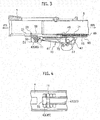
- a steering column device 1 is a manual-type steering column device 1.
- the steering column device 1 includes: an attachment bracket 2 for fixing the steering column device 1 to a vehicle body; an outer column 7 supported to the attachment bracket 2 in such a way as to be swingable in the vehicle vertical direction (capable of adjusting its tilt position); an inner column 9 supported to the outer column 7 in such a way as to be movable in the vehicle longitudinal direction (capable of adjusting its telescopic position).
- the steering column device 1 further includes: a locking mechanism 60 configured to fasten the attachment bracket 2, the outer column 7, and the inner column 9; an energy absorbing mechanism 61 configured to absorb impact energy in a secondary collision; and a telescopic-position restricting mechanism 62 configured to define an adjustment range for the position of the inner column 9 relative to the outer column 7 in the vehicle longitudinal direction (telescopic position).
- the inner column 9 is configured to be inserted in the outer column 7 in such a way as to be movable in the tube-axis direction, thereby allowing telescopic operation.
- a locked state the front-rear position of the inner column 9 relative to the outer column 7 is locked (fixed) by a locking member 68.
- an operating lever 15 is pushed down, so that the lock is released and the front-rear position of the inner column 9 relative to the outer column 7 can be changed.
- the operating lever 15 is pushed up and locked, so that the front-rear position of the inner column 9 relative to the outer column 7 is fixed.
- the attachment bracket 2 includes a front fixing part 3 and a rear fixing part 5 configured to be fixed to the vehicle body's steering member (not illustrated).
- the front fixing part 3 includes a pivot portion 17 configured to pivotally support the outer column 7 such that the outer column 7 can be swung, and the rear fixing part 5 includes a pair of hanging portions hanging from its right and left edges. Both hanging portions are provided with a tilt slot bored to define a tilt-position adjustment range along the vehicle vertical direction (tilt direction).
- the tilt slot is formed of an elongated hole arched about the pivot portion.
- the outer column 7 is formed in a tubular shape and arranged between the pair of hanging portions of the attachment bracket 2 along the vehicle longitudinal direction.
- the outer column 7 has its front end portion pivotally supported to the pivot portion 17 of the front fixing part 3 of the attachment bracket 2 with a bolt. In this way, the rear end side of the outer column 7 can swing in the vehicle vertical direction.
- the outer column 7 includes a slit 55 penetrating through the lower surface of a tubular wall 21 and extending from the rear edge along the tube-axis direction.
- the dimension of the slit 55 in the tube-axis direction is set such that the slit 55 extends to a portion of the outer column 7 overlapping the front end of the inner jacket 9 in a state where the inner jacket 9, inserted in the rear end of the outer column 7, is fully contracted by absorbing an impact and moved forward relative to the outer column 7.
- a pair of clamp parts 63 are provided to extend from the opposite edges of the slit 55 extending along the tube-axis direction. Both clamp parts 63 are provided to extend along the vehicle vertical direction at sections located on the rear end side of the slit 55 and facing the hanging portions of the rear fixing part 5. Moreover, an operating shaft 64 penetrates through both clamp parts 63 in such a way as to be turnable about its axis.
- a pair of guiderail supporting parts 65 are provided to extend downward from front end portions of the opposite edges of the slit 55 extending along the tube-axis direction, and a supporting pin 66 is laid between the guiderail supporting parts 65.
- a later-described guiderail 67 is swingably supported on the supporting pin 66.
- a pair of stopper parts 31 are provided to extend downward on the rear side of the guiderail supporting parts 65, and a later-described restricting member 11 is held between the stopper parts.
- the inner column 9 is formed in a tubular shape and inserted in the tube of the outer column 7 in such a way as to be movable in the tube-axis direction.
- a steering shaft 10 is rotatably supported inside the tubes of the inner column 9 and the outer column 7.
- the steering shaft 10 includes a lower shaft 10L housed in the outer column 7 and an upper shaft 10U housed in the inner column 9.
- the upper shaft 10U and the lower shaft 10L are coupled to each other with a spline(s).
- the upper shaft 10U and the lower shaft 10L can rotate together about an axis, and the upper shaft 10U can move relative to the lower shaft 10L in the direction of the axis.
- the locking mechanism 60 includes the operating lever 15, the operating shaft 64, the guiderail 67, the locking member 68, a locked member 69, and a cam member 57.
- the operating shaft 64 has a shaft shape, penetrates through the tilt slots in both hanging portions of the attachment bracket 2 and both clamp parts 63 of the outer column 7 along the vehicle width direction, and is supported to the clamp parts 63 in such a way as to be turnable about its axis.
- the operating lever 15 is disposed on the operating shaft 64.
- the front end of the guiderail 67 is pivotally supported to the guiderail supporting parts 65, provided on the outer periphery of the outer column 7, with the supporting pin 66 such that the guiderail 67 can be swung, while the rear end side is held between the locking member 68 and the cam member 57.
- the cam member 57 presses the locking member 68 against the locked member 69 via the guiderail 67.
- a force (frictional force) in the direction of rotation of the cam member 57 is not transmitted to the locking member 68, and only a force in the radial direction is transmitted to the locking member 68.
- the inner column 9 can be fixed without being displaced in the tube-axis direction from the desired position when a locking operation is performed.
- the locking member 68 forms a row of claws configured to engage with the locked member 69, and a wire-member catching part 70 is formed in the locking member 68. Also, a spring member 71 formed of a leaf spring is disposed between the locking member 68 and the locked member 69.
- the wire-member catching part 70 is a recess provided in the upper surface of the locking member 68, and supports a second end 49 of a load absorbing wire 13.
- the locked member 69 is fixed to the outer peripheral surface of the inner column 9 along the tube-axis direction. Also, in the locked member 69, a plurality of catching recesses (locking holes) are formed opening successively in the longitudinal direction.
- the cam member 57 is formed in a cylindrical shape, and on the outer peripheral surface of its center in the axial direction is formed a driven cam part protruding in the radial direction. Further, a rubbing part is formed on the outer peripheral surface of each end portion of the cam member 57 in the axial direction, and the load absorbing wire 13 is configured to be rubbed against the rubbing part.
- the restricting member 11 is provided through the tubular wall 21 at a lower section of the outer column 7 in such a way as to be capable of coming in and out of the tubular wall 21 in its thickness direction.
- This restricting member 11 is configured to restrict the front-end position of the inner column 9 in the direction of telescopic contraction thereof and is arranged to be releasable from the outer column 7.
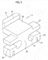
- the restricting member 11 integrally includes a lower holding part 23 extending in the vehicle width direction, a linking part 25 extending upward from a center portion of the lower holding part 23 in the vehicle width direction, an upper holding part 27 linked to the lower holding part 23 by the linking part 25, an upper extension part 29 provided on the upper holding part 27, and a stopper part 31 formed at the front end of the upper extension part 29. Further, this stopper part 31 is held in the tubular wall 21 at the lower section of the outer column 7. Furthermore, the upper surfaces of the right and left sides of the lower holding part 23 are formed as flat wire push surfaces 26, and the vehicle rear side of the stopper part 31 is formed as a contact surface 33.
- This contact surface 33 restricts the front-end position of the inner column 9 in the direction of telescopic contraction thereof. Specifically, the front-rear position at which a lower portion of the front end of the inner column 9 contacts the contact surface 33 in telescopic adjustment is the foremost position in the direction of telescopic contraction. Moreover, a pair of wire insertion parts 35 into which to insert the load absorbing wire 13 are formed in the lower holding part 23 by the right and left of the linking part 25. Meanwhile, in total four protrusions 37 in the shape of a triangular prism extending in the vertical direction are provided on right and left portions of the front surface of the lower holding part 23 and right and left portions of the rear surface of the lower holding part 23.
- the above load absorbing wire 13 is curved in a J-shape in a side view.
- the load absorbing wire 13 is integrally formed of: a pair of right and left main parts 41 extending straight in the vehicle longitudinal direction substantially in parallel to the outer column 7; bent parts 43 (first ends 45) formed in L-shapes in a plan view and bent outward in directions crossing the outer column 7 from the front ends of the main parts 41 on the vehicle front side; curved parts 47 formed in a U-shape in the side view and curved upward from the rear ends of the main parts 41 on the vehicle rear side; and the second end 49 extending toward the vehicle front side from the curved parts 47 with the tips formed integrally with each other in the vehicle width direction.
- the second end 49 of the load absorbing wire 13 is fixed to the inner column 9 by the wire-member catching part 70 during the locked state.
- a wire holding part 51 protruding downward is provided at the lower section of the outer column 7.
- notches 53 are formed with their vehicle rear sides open to be capable of housing the bent parts 43 of the load absorbing wire 13.
- the slit 55 which has a rectangular shape along the front-rear direction, is formed in the lower section of the outer column 7.
- the cam member 57 projects downward from the lower section of the outer column 7. The load absorbing wire 13 is routed under this cam member 57.
- the inner column 9 moves toward the front side together with the locking member 68 and the second end 49 of the load absorbing wire 13. Then, the curved parts 47 of the load absorbing wire 13 are pulled around the outer peripheral surface of the cam member 57, and thereafter the curved parts 47 and the main parts 41 of the load absorbing wire 13 are rubbed against the rubbing parts on the outer peripheral surface of the cam member 57 and deformed accordingly. As a result, the impact energy is absorbed.
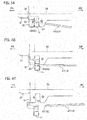
- the stopper part 31 of the restricting member 11 is disposed to project to a radially inner side (upper side in Fig. 6A ) of an inner peripheral surface 59 of the tubular wall 21 of the outer column 7.
- the triangular-prism protrusions 37 illustrated in Fig. 5 , biting into the wire holding part 51 at the lower section of the outer column 7, the restricting member 11 is held in the wire holding part 51 and does not get released by its own weight.
- the bent parts 43 of the load absorbing wire 13 are housed in the notches 53 of the wire holding part 51.
- the first ends 45 of the load absorbing wire 13 move toward the vehicle rear side upon application of a load of the preset value or greater to the inner column 9 toward the vehicle front side, the first ends 45 of the load absorbing wire 13 can push down the wire push surfaces 26 of the restricting member 11.
- the restricting member 11 can be forcibly released from the wire holding part 51 of the outer column 7. This makes it possible to further suppress abrupt increase in impact absorption load in the middle of absorption of the impact energy.
- a restricting member according to the second embodiment is such that the wire push surfaces of its lower holding part are formed as inclined surfaces.
- a restricting member 111 integrally includes a lower holding part 23 extending in the vehicle width direction, a linking part 25 extending upward from a center portion of the lower holding part 23 in the vehicle width direction, an upper holding part 27 linked to the lower holding part 23 by the linking part 25, an upper extension part 29 provided on the upper holding part 27, and a stopper part 31 formed at the front end of the upper extension part 29.
- the upper surfaces of the right and left sides of the lower holding part 23 are formed as wire push surfaces 120 which are inclined surfaces 126 extending obliquely upward toward the rear side relative to the tube-axis direction of the outer column 7 in a side view.
- the vehicle rear side of the stopper part 31 is formed as a contact surface 33.
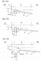
- the stopper part 31 of the restricting member 111 is disposed to project to a radially inner side (upper side in Fig. 11A ) of the inner peripheral surface 59 of the tubular wall 21 of the outer column 7.
- the restricting member 111 With triangular-prism protrusions 37 on the restricting member 111 biting into the wire holding part 51 at the lower section of the outer column 7, the restricting member 111 is held in the wire holding part 51 and does not get released by its own weight.
- the bent parts 43 (first ends 45) of the load absorbing wire 13 are housed in the notches 53 of the wire holding part 51.
- the wire push surfaces 120 in the second embodiment are formed as the inclined surface 126, which extend obliquely upward toward the rear side in the side view. Hence, when the bent parts 43 of the load absorbing wire 13 move toward the vehicle rear side, the restricting member 111 is moved downward to a greater extent than the first embodiment. Consequently, the restricting member 111 is released from the wire holding part 51 of the outer column 7, as illustrated in Figs. 11B and 11C .
- the restricting member 111 with which the first ends 45 of the load absorbing wire 13 engage, includes the inclined surfaces 126, which extend obliquely upward toward the rear side relative to the tube-axis direction of the outer column 7 in a side view.
- the bent parts 43 (first ends 45) of the load absorbing wire 13 push down the inclined surfaces 126 of the restricting member 111. Accordingly, the bent parts 43 of the load absorbing wire 13 can push down the restricting member 111 to a greater extent.
- a load absorbing wire according to the third embodiment is such that its first ends 45 (front ends) are bent in a V shape in a side view.
- bent parts 243 formed in a V shape in a side view are provided at first ends 45 of a load absorbing wire 13. More specifically, the front ends of the load absorbing wire 13 include main parts 41 extending straight in the side view and the bent parts 243 bent from the front ends of the main parts 41 in such a way as to extend obliquely downward toward the front side. Meanwhile, the third embodiment uses the same restricting member 11 as the first embodiment.
- the stopper part 31 of the restricting member 11 is disposed to project to a radially inner side (upper side in Fig. 12A ) of the inner peripheral surface 59 of the tubular wall 21 of the outer column 7.
- the restricting member 11 With the triangular-prism protrusions 37 of the restricting member 11 biting into the wire holding part 51 at the lower section of the outer column 7, the restricting member 11 is held in the wire holding part 51 and does not get released by its own weight.
- the bent parts 243 at the first ends 45 of the load absorbing wire 13 push down the restricting member 11. Accordingly, the bent parts 243 at the first ends 45 of the load absorbing wire 13 can push down the restricting member 11 to a greater extent.
- a restricting member 311 includes an upper part 313 movable in the vertical direction and a lower part 315 pivotally supported in such a way as to be capable of turning to push down the upper part 313.
- the upper part 313 includes a catching part 317 provided on the lower side, and a stopper part 319 provided on the catching part 317.
- the stopper part 319 normally projects to a radially inner side (upper side in Figs. 13 and 14 ) of the inner peripheral surface 59 of the tubular wall 21 of the outer column 7.
- the stopper part 319 restricts the front-end position of the inner column 9 in the direction of telescopic contraction thereof.
- the catching part 317 is configured to be pushed down by contacting the lower part 315, as described later.
- the lower part 315 is a member bent in an L-shape in a side view with a front leg part 321 extending toward the front side and a lower leg part 323 extending downward from the rear end of the front leg part 321, and is pivotally supported at its middle part to the outer column 7 via a turn shaft portion 325 such that the lower part 315 can turn. Also, at the lower end of the lower leg part 323, a wire hook portion 327 is formed which is recessed upward. The first ends 45 of the load absorbing wire 13 are inserted and caught in this wire hook portion 327.
- the stopper part 319 projects to a radially inner side (upper side in Figs. 14A to 14B ) of the inner peripheral surface 59 of the tubular wall 21 of the outer column 7.
- the restricting member 311 includes the upper part 313 provided at its upper end with the stopper part 319 configured to project to a radially inner side of the tubular wall 21 of the outer column 7, and the lower part 315 configured to be turnable with the first ends 45 of the load absorbing wire 13 caught thereon.
- the lower part 315 turns about the turn shaft portion 325 to push down the upper part 313. In this way, the first ends 45 of the load absorbing wire 13 can push down the stopper part 319 of the restricting member 311 to a greater extent.
Landscapes
- Engineering & Computer Science (AREA)
- Chemical & Material Sciences (AREA)
- Combustion & Propulsion (AREA)
- Transportation (AREA)
- Mechanical Engineering (AREA)
- Steering Controls (AREA)
Applications Claiming Priority (1)
| Application Number | Priority Date | Filing Date | Title |
|---|---|---|---|
| JP2016063037A JP6609211B2 (ja) | 2016-03-28 | 2016-03-28 | ステアリングコラム装置 |
Publications (2)
| Publication Number | Publication Date |
|---|---|
| EP3225504A1 true EP3225504A1 (de) | 2017-10-04 |
| EP3225504B1 EP3225504B1 (de) | 2019-05-08 |
Family
ID=58387743
Family Applications (1)
| Application Number | Title | Priority Date | Filing Date |
|---|---|---|---|
| EP17161826.7A Active EP3225504B1 (de) | 2016-03-28 | 2017-03-20 | Lenksäulenvorrichtung |
Country Status (4)
| Country | Link |
|---|---|
| US (1) | US10040473B2 (de) |
| EP (1) | EP3225504B1 (de) |
| JP (1) | JP6609211B2 (de) |
| CN (1) | CN107235069B (de) |
Families Citing this family (7)
| Publication number | Priority date | Publication date | Assignee | Title |
|---|---|---|---|---|
| US9849906B2 (en) * | 2015-03-27 | 2017-12-26 | Fuji Kiko Co., Ltd. | Steering column device |
| JP7160806B2 (ja) * | 2017-06-14 | 2022-10-25 | 株式会社山田製作所 | ステアリング装置 |
| JP6905918B2 (ja) * | 2017-11-17 | 2021-07-21 | 株式会社山田製作所 | ステアリング装置 |
| JP6941542B2 (ja) * | 2017-11-17 | 2021-09-29 | 株式会社山田製作所 | ステアリング装置 |
| DE102017223470A1 (de) * | 2017-12-20 | 2019-06-27 | Thyssenkrupp Ag | Motorisch verstellbare Lenksäule für ein Kraftfahrzeug |
| CN111918809B (zh) * | 2018-03-27 | 2022-09-20 | 日本精工株式会社 | 转向装置 |
| JP7093722B2 (ja) * | 2018-12-18 | 2022-06-30 | 富士機工株式会社 | ステアリングコラム装置 |
Citations (3)
| Publication number | Priority date | Publication date | Assignee | Title |
|---|---|---|---|---|
| JP2005001517A (ja) * | 2003-06-12 | 2005-01-06 | Nsk Ltd | ステアリング装置 |
| WO2012000593A1 (de) | 2010-06-28 | 2012-01-05 | Thyssenkrupp Presta Aktiengesellschaft | Verstellbare lenksäule für ein kraftfahrzeug |
| EP3072779A1 (de) * | 2015-03-27 | 2016-09-28 | FUJI KIKO Co., Ltd. | Lenksäulenvorrichtung |
Family Cites Families (10)
| Publication number | Priority date | Publication date | Assignee | Title |
|---|---|---|---|---|
| DE10203917C1 (de) * | 2002-01-31 | 2003-07-24 | Daimler Chrysler Ag | Lenksäulenanordnung für ein Kraftfahrzeug |
| JP4897541B2 (ja) * | 2007-03-30 | 2012-03-14 | 株式会社ジェイテクト | 衝撃吸収式操舵装置 |
| CN101570213B (zh) * | 2009-06-16 | 2012-09-05 | 奇瑞汽车股份有限公司 | 一种吸能式汽车转向管柱 |
| JP5662115B2 (ja) * | 2010-01-20 | 2015-01-28 | 株式会社山田製作所 | ステアリング装置 |
| US8562020B2 (en) * | 2010-06-16 | 2013-10-22 | Nsk Ltd. | Steering column support apparatus |
| JP2015044507A (ja) * | 2013-07-31 | 2015-03-12 | 株式会社ジェイテクト | ステアリング装置 |
| JP5983893B2 (ja) * | 2014-06-09 | 2016-09-06 | 日本精工株式会社 | ステアリング装置 |
| CN104843050B (zh) * | 2014-09-05 | 2017-08-04 | 北汽福田汽车股份有限公司 | 一种转向管柱总成及具有其的车辆 |
| JP2016185719A (ja) * | 2015-03-27 | 2016-10-27 | 富士機工株式会社 | ステアリングコラム装置 |
| JP6694739B2 (ja) * | 2016-03-25 | 2020-05-20 | 富士機工株式会社 | ステアリングコラム装置 |
-
2016
- 2016-03-28 JP JP2016063037A patent/JP6609211B2/ja active Active
-
2017
- 2017-03-20 US US15/462,946 patent/US10040473B2/en active Active
- 2017-03-20 CN CN201710166102.4A patent/CN107235069B/zh active Active
- 2017-03-20 EP EP17161826.7A patent/EP3225504B1/de active Active
Patent Citations (3)
| Publication number | Priority date | Publication date | Assignee | Title |
|---|---|---|---|---|
| JP2005001517A (ja) * | 2003-06-12 | 2005-01-06 | Nsk Ltd | ステアリング装置 |
| WO2012000593A1 (de) | 2010-06-28 | 2012-01-05 | Thyssenkrupp Presta Aktiengesellschaft | Verstellbare lenksäule für ein kraftfahrzeug |
| EP3072779A1 (de) * | 2015-03-27 | 2016-09-28 | FUJI KIKO Co., Ltd. | Lenksäulenvorrichtung |
Also Published As
| Publication number | Publication date |
|---|---|
| US10040473B2 (en) | 2018-08-07 |
| JP2017177826A (ja) | 2017-10-05 |
| EP3225504B1 (de) | 2019-05-08 |
| CN107235069A (zh) | 2017-10-10 |
| CN107235069B (zh) | 2019-03-29 |
| US20170274923A1 (en) | 2017-09-28 |
| JP6609211B2 (ja) | 2019-11-20 |
Similar Documents
| Publication | Publication Date | Title |
|---|---|---|
| EP3225504B1 (de) | Lenksäulenvorrichtung | |
| US10160475B2 (en) | Steering column device | |
| US9849906B2 (en) | Steering column device | |
| US9376136B2 (en) | Steering device | |
| US9242667B2 (en) | Steering device | |
| JP6518099B2 (ja) | ステアリング装置 | |
| US10737714B2 (en) | Steering device | |
| CN107521550B (zh) | 操舵装置 | |
| US10919559B2 (en) | Steering device | |
| CN107792162B (zh) | 转向装置 | |
| US20140260763A1 (en) | Steering column energy absorbing rake lock | |
| EP3124355B1 (de) | Lenksäuleneinrichtung | |
| JP6985918B2 (ja) | ステアリング装置 | |
| JP6539084B2 (ja) | ステアリングコラム装置 | |
| JP2022189046A (ja) | ステアリング装置 | |
| EP3075629A2 (de) | Lenksäulenvorrichtung | |
| US8794671B1 (en) | Anti-unlocking device for adjustable steering column | |
| JP2016190632A (ja) | ステアリングコラム装置 | |
| JP2022189047A (ja) | ステアリング装置 | |
| KR102654521B1 (ko) | 자동차의 조향 컬럼 | |
| JP2006182062A (ja) | ステアリングコラム装置 | |
| US20200189645A1 (en) | Steering column device |
Legal Events
| Date | Code | Title | Description |
|---|---|---|---|
| PUAI | Public reference made under article 153(3) epc to a published international application that has entered the european phase |
Free format text: ORIGINAL CODE: 0009012 |
|
| STAA | Information on the status of an ep patent application or granted ep patent |
Free format text: STATUS: THE APPLICATION HAS BEEN PUBLISHED |
|
| AK | Designated contracting states |
Kind code of ref document: A1 Designated state(s): AL AT BE BG CH CY CZ DE DK EE ES FI FR GB GR HR HU IE IS IT LI LT LU LV MC MK MT NL NO PL PT RO RS SE SI SK SM TR |
|
| AX | Request for extension of the european patent |
Extension state: BA ME |
|
| STAA | Information on the status of an ep patent application or granted ep patent |
Free format text: STATUS: REQUEST FOR EXAMINATION WAS MADE |
|
| 17P | Request for examination filed |
Effective date: 20180404 |
|
| RBV | Designated contracting states (corrected) |
Designated state(s): AL AT BE BG CH CY CZ DE DK EE ES FI FR GB GR HR HU IE IS IT LI LT LU LV MC MK MT NL NO PL PT RO RS SE SI SK SM TR |
|
| GRAP | Despatch of communication of intention to grant a patent |
Free format text: ORIGINAL CODE: EPIDOSNIGR1 |
|
| STAA | Information on the status of an ep patent application or granted ep patent |
Free format text: STATUS: GRANT OF PATENT IS INTENDED |
|
| RIC1 | Information provided on ipc code assigned before grant |
Ipc: B62D 1/19 20060101ALI20181116BHEP Ipc: B62D 1/189 20060101ALI20181116BHEP Ipc: B62D 1/184 20060101AFI20181116BHEP Ipc: B62D 1/185 20060101ALI20181116BHEP Ipc: B62D 1/187 20060101ALI20181116BHEP Ipc: B62D 1/18 20060101ALI20181116BHEP |
|
| INTG | Intention to grant announced |
Effective date: 20181206 |
|
| GRAS | Grant fee paid |
Free format text: ORIGINAL CODE: EPIDOSNIGR3 |
|
| GRAA | (expected) grant |
Free format text: ORIGINAL CODE: 0009210 |
|
| STAA | Information on the status of an ep patent application or granted ep patent |
Free format text: STATUS: THE PATENT HAS BEEN GRANTED |
|
| AK | Designated contracting states |
Kind code of ref document: B1 Designated state(s): AL AT BE BG CH CY CZ DE DK EE ES FI FR GB GR HR HU IE IS IT LI LT LU LV MC MK MT NL NO PL PT RO RS SE SI SK SM TR |
|
| REG | Reference to a national code |
Ref country code: GB Ref legal event code: FG4D |
|
| REG | Reference to a national code |
Ref country code: CH Ref legal event code: EP Ref country code: AT Ref legal event code: REF Ref document number: 1129685 Country of ref document: AT Kind code of ref document: T Effective date: 20190515 |
|
| REG | Reference to a national code |
Ref country code: DE Ref legal event code: R096 Ref document number: 602017003747 Country of ref document: DE Ref country code: IE Ref legal event code: FG4D |
|
| REG | Reference to a national code |
Ref country code: NL Ref legal event code: MP Effective date: 20190508 |
|
| REG | Reference to a national code |
Ref country code: LT Ref legal event code: MG4D |
|
| PG25 | Lapsed in a contracting state [announced via postgrant information from national office to epo] |
Ref country code: NO Free format text: LAPSE BECAUSE OF FAILURE TO SUBMIT A TRANSLATION OF THE DESCRIPTION OR TO PAY THE FEE WITHIN THE PRESCRIBED TIME-LIMIT Effective date: 20190808 Ref country code: AL Free format text: LAPSE BECAUSE OF FAILURE TO SUBMIT A TRANSLATION OF THE DESCRIPTION OR TO PAY THE FEE WITHIN THE PRESCRIBED TIME-LIMIT Effective date: 20190508 Ref country code: FI Free format text: LAPSE BECAUSE OF FAILURE TO SUBMIT A TRANSLATION OF THE DESCRIPTION OR TO PAY THE FEE WITHIN THE PRESCRIBED TIME-LIMIT Effective date: 20190508 Ref country code: SE Free format text: LAPSE BECAUSE OF FAILURE TO SUBMIT A TRANSLATION OF THE DESCRIPTION OR TO PAY THE FEE WITHIN THE PRESCRIBED TIME-LIMIT Effective date: 20190508 Ref country code: NL Free format text: LAPSE BECAUSE OF FAILURE TO SUBMIT A TRANSLATION OF THE DESCRIPTION OR TO PAY THE FEE WITHIN THE PRESCRIBED TIME-LIMIT Effective date: 20190508 Ref country code: HR Free format text: LAPSE BECAUSE OF FAILURE TO SUBMIT A TRANSLATION OF THE DESCRIPTION OR TO PAY THE FEE WITHIN THE PRESCRIBED TIME-LIMIT Effective date: 20190508 Ref country code: PT Free format text: LAPSE BECAUSE OF FAILURE TO SUBMIT A TRANSLATION OF THE DESCRIPTION OR TO PAY THE FEE WITHIN THE PRESCRIBED TIME-LIMIT Effective date: 20190908 Ref country code: LT Free format text: LAPSE BECAUSE OF FAILURE TO SUBMIT A TRANSLATION OF THE DESCRIPTION OR TO PAY THE FEE WITHIN THE PRESCRIBED TIME-LIMIT Effective date: 20190508 Ref country code: ES Free format text: LAPSE BECAUSE OF FAILURE TO SUBMIT A TRANSLATION OF THE DESCRIPTION OR TO PAY THE FEE WITHIN THE PRESCRIBED TIME-LIMIT Effective date: 20190508 |
|
| PG25 | Lapsed in a contracting state [announced via postgrant information from national office to epo] |
Ref country code: GR Free format text: LAPSE BECAUSE OF FAILURE TO SUBMIT A TRANSLATION OF THE DESCRIPTION OR TO PAY THE FEE WITHIN THE PRESCRIBED TIME-LIMIT Effective date: 20190809 Ref country code: BG Free format text: LAPSE BECAUSE OF FAILURE TO SUBMIT A TRANSLATION OF THE DESCRIPTION OR TO PAY THE FEE WITHIN THE PRESCRIBED TIME-LIMIT Effective date: 20190808 Ref country code: RS Free format text: LAPSE BECAUSE OF FAILURE TO SUBMIT A TRANSLATION OF THE DESCRIPTION OR TO PAY THE FEE WITHIN THE PRESCRIBED TIME-LIMIT Effective date: 20190508 Ref country code: LV Free format text: LAPSE BECAUSE OF FAILURE TO SUBMIT A TRANSLATION OF THE DESCRIPTION OR TO PAY THE FEE WITHIN THE PRESCRIBED TIME-LIMIT Effective date: 20190508 |
|
| REG | Reference to a national code |
Ref country code: AT Ref legal event code: MK05 Ref document number: 1129685 Country of ref document: AT Kind code of ref document: T Effective date: 20190508 |
|
| PG25 | Lapsed in a contracting state [announced via postgrant information from national office to epo] |
Ref country code: CZ Free format text: LAPSE BECAUSE OF FAILURE TO SUBMIT A TRANSLATION OF THE DESCRIPTION OR TO PAY THE FEE WITHIN THE PRESCRIBED TIME-LIMIT Effective date: 20190508 Ref country code: RO Free format text: LAPSE BECAUSE OF FAILURE TO SUBMIT A TRANSLATION OF THE DESCRIPTION OR TO PAY THE FEE WITHIN THE PRESCRIBED TIME-LIMIT Effective date: 20190508 Ref country code: EE Free format text: LAPSE BECAUSE OF FAILURE TO SUBMIT A TRANSLATION OF THE DESCRIPTION OR TO PAY THE FEE WITHIN THE PRESCRIBED TIME-LIMIT Effective date: 20190508 Ref country code: AT Free format text: LAPSE BECAUSE OF FAILURE TO SUBMIT A TRANSLATION OF THE DESCRIPTION OR TO PAY THE FEE WITHIN THE PRESCRIBED TIME-LIMIT Effective date: 20190508 Ref country code: DK Free format text: LAPSE BECAUSE OF FAILURE TO SUBMIT A TRANSLATION OF THE DESCRIPTION OR TO PAY THE FEE WITHIN THE PRESCRIBED TIME-LIMIT Effective date: 20190508 Ref country code: SK Free format text: LAPSE BECAUSE OF FAILURE TO SUBMIT A TRANSLATION OF THE DESCRIPTION OR TO PAY THE FEE WITHIN THE PRESCRIBED TIME-LIMIT Effective date: 20190508 |
|
| REG | Reference to a national code |
Ref country code: DE Ref legal event code: R097 Ref document number: 602017003747 Country of ref document: DE |
|
| PG25 | Lapsed in a contracting state [announced via postgrant information from national office to epo] |
Ref country code: IT Free format text: LAPSE BECAUSE OF FAILURE TO SUBMIT A TRANSLATION OF THE DESCRIPTION OR TO PAY THE FEE WITHIN THE PRESCRIBED TIME-LIMIT Effective date: 20190508 Ref country code: SM Free format text: LAPSE BECAUSE OF FAILURE TO SUBMIT A TRANSLATION OF THE DESCRIPTION OR TO PAY THE FEE WITHIN THE PRESCRIBED TIME-LIMIT Effective date: 20190508 |
|
| PLBE | No opposition filed within time limit |
Free format text: ORIGINAL CODE: 0009261 |
|
| STAA | Information on the status of an ep patent application or granted ep patent |
Free format text: STATUS: NO OPPOSITION FILED WITHIN TIME LIMIT |
|
| PG25 | Lapsed in a contracting state [announced via postgrant information from national office to epo] |
Ref country code: TR Free format text: LAPSE BECAUSE OF FAILURE TO SUBMIT A TRANSLATION OF THE DESCRIPTION OR TO PAY THE FEE WITHIN THE PRESCRIBED TIME-LIMIT Effective date: 20190508 |
|
| 26N | No opposition filed |
Effective date: 20200211 |
|
| PG25 | Lapsed in a contracting state [announced via postgrant information from national office to epo] |
Ref country code: PL Free format text: LAPSE BECAUSE OF FAILURE TO SUBMIT A TRANSLATION OF THE DESCRIPTION OR TO PAY THE FEE WITHIN THE PRESCRIBED TIME-LIMIT Effective date: 20190508 |
|
| PG25 | Lapsed in a contracting state [announced via postgrant information from national office to epo] |
Ref country code: SI Free format text: LAPSE BECAUSE OF FAILURE TO SUBMIT A TRANSLATION OF THE DESCRIPTION OR TO PAY THE FEE WITHIN THE PRESCRIBED TIME-LIMIT Effective date: 20190508 |
|
| PG25 | Lapsed in a contracting state [announced via postgrant information from national office to epo] |
Ref country code: MC Free format text: LAPSE BECAUSE OF FAILURE TO SUBMIT A TRANSLATION OF THE DESCRIPTION OR TO PAY THE FEE WITHIN THE PRESCRIBED TIME-LIMIT Effective date: 20190508 |
|
| REG | Reference to a national code |
Ref country code: CH Ref legal event code: PL |
|
| REG | Reference to a national code |
Ref country code: BE Ref legal event code: MM Effective date: 20200331 |
|
| PG25 | Lapsed in a contracting state [announced via postgrant information from national office to epo] |
Ref country code: LU Free format text: LAPSE BECAUSE OF NON-PAYMENT OF DUE FEES Effective date: 20200320 |
|
| PG25 | Lapsed in a contracting state [announced via postgrant information from national office to epo] |
Ref country code: LI Free format text: LAPSE BECAUSE OF NON-PAYMENT OF DUE FEES Effective date: 20200331 Ref country code: CH Free format text: LAPSE BECAUSE OF NON-PAYMENT OF DUE FEES Effective date: 20200331 Ref country code: IE Free format text: LAPSE BECAUSE OF NON-PAYMENT OF DUE FEES Effective date: 20200320 |
|
| PG25 | Lapsed in a contracting state [announced via postgrant information from national office to epo] |
Ref country code: BE Free format text: LAPSE BECAUSE OF NON-PAYMENT OF DUE FEES Effective date: 20200331 |
|
| GBPC | Gb: european patent ceased through non-payment of renewal fee |
Effective date: 20210320 |
|
| PG25 | Lapsed in a contracting state [announced via postgrant information from national office to epo] |
Ref country code: GB Free format text: LAPSE BECAUSE OF NON-PAYMENT OF DUE FEES Effective date: 20210320 |
|
| PG25 | Lapsed in a contracting state [announced via postgrant information from national office to epo] |
Ref country code: MT Free format text: LAPSE BECAUSE OF FAILURE TO SUBMIT A TRANSLATION OF THE DESCRIPTION OR TO PAY THE FEE WITHIN THE PRESCRIBED TIME-LIMIT Effective date: 20190508 Ref country code: CY Free format text: LAPSE BECAUSE OF FAILURE TO SUBMIT A TRANSLATION OF THE DESCRIPTION OR TO PAY THE FEE WITHIN THE PRESCRIBED TIME-LIMIT Effective date: 20190508 |
|
| PG25 | Lapsed in a contracting state [announced via postgrant information from national office to epo] |
Ref country code: MK Free format text: LAPSE BECAUSE OF FAILURE TO SUBMIT A TRANSLATION OF THE DESCRIPTION OR TO PAY THE FEE WITHIN THE PRESCRIBED TIME-LIMIT Effective date: 20190508 Ref country code: IS Free format text: LAPSE BECAUSE OF FAILURE TO SUBMIT A TRANSLATION OF THE DESCRIPTION OR TO PAY THE FEE WITHIN THE PRESCRIBED TIME-LIMIT Effective date: 20190908 |
|
| PGFP | Annual fee paid to national office [announced via postgrant information from national office to epo] |
Ref country code: FR Payment date: 20230329 Year of fee payment: 7 |
|
| REG | Reference to a national code |
Ref country code: DE Ref legal event code: R081 Ref document number: 602017003747 Country of ref document: DE Owner name: JTEKT COLUMN SYSTEMS CORP., KOSAI-SHI, JP Free format text: FORMER OWNER: FUJI KIKO CO., LTD., KOSAI-SHI, SHIZUOKA-KEN, JP |
|
| PGFP | Annual fee paid to national office [announced via postgrant information from national office to epo] |
Ref country code: DE Payment date: 20240327 Year of fee payment: 8 |