EP3223540B1 - Système de microphone optique - Google Patents
Système de microphone optique Download PDFInfo
- Publication number
- EP3223540B1 EP3223540B1 EP17160682.5A EP17160682A EP3223540B1 EP 3223540 B1 EP3223540 B1 EP 3223540B1 EP 17160682 A EP17160682 A EP 17160682A EP 3223540 B1 EP3223540 B1 EP 3223540B1
- Authority
- EP
- European Patent Office
- Prior art keywords
- linear polarization
- optical beam
- frequency
- signal
- optical
- Prior art date
- Legal status (The legal status is an assumption and is not a legal conclusion. Google has not performed a legal analysis and makes no representation as to the accuracy of the status listed.)
- Active
Links
- 230000003287 optical effect Effects 0.000 title claims description 222
- 230000010287 polarization Effects 0.000 claims description 171
- 238000001514 detection method Methods 0.000 claims description 60
- 230000000737 periodic effect Effects 0.000 claims description 18
- 230000007704 transition Effects 0.000 claims description 18
- 230000010355 oscillation Effects 0.000 claims description 15
- 238000000034 method Methods 0.000 claims description 10
- 230000004044 response Effects 0.000 claims description 10
- 230000000638 stimulation Effects 0.000 description 16
- 238000010586 diagram Methods 0.000 description 9
- 230000008859 change Effects 0.000 description 8
- 238000006073 displacement reaction Methods 0.000 description 5
- 239000012528 membrane Substances 0.000 description 4
- 230000002939 deleterious effect Effects 0.000 description 3
- 230000001133 acceleration Effects 0.000 description 2
- 230000000694 effects Effects 0.000 description 2
- 230000002730 additional effect Effects 0.000 description 1
- 230000003679 aging effect Effects 0.000 description 1
- 230000001419 dependent effect Effects 0.000 description 1
- 238000001914 filtration Methods 0.000 description 1
- 238000011896 sensitive detection Methods 0.000 description 1
- 230000035945 sensitivity Effects 0.000 description 1
- 230000003068 static effect Effects 0.000 description 1
- 239000000758 substrate Substances 0.000 description 1
- 230000000007 visual effect Effects 0.000 description 1
Images


Classifications
-
- H—ELECTRICITY
- H04—ELECTRIC COMMUNICATION TECHNIQUE
- H04R—LOUDSPEAKERS, MICROPHONES, GRAMOPHONE PICK-UPS OR LIKE ACOUSTIC ELECTROMECHANICAL TRANSDUCERS; DEAF-AID SETS; PUBLIC ADDRESS SYSTEMS
- H04R23/00—Transducers other than those covered by groups H04R9/00 - H04R21/00
- H04R23/008—Transducers other than those covered by groups H04R9/00 - H04R21/00 using optical signals for detecting or generating sound
-
- H—ELECTRICITY
- H04—ELECTRIC COMMUNICATION TECHNIQUE
- H04R—LOUDSPEAKERS, MICROPHONES, GRAMOPHONE PICK-UPS OR LIKE ACOUSTIC ELECTROMECHANICAL TRANSDUCERS; DEAF-AID SETS; PUBLIC ADDRESS SYSTEMS
- H04R23/00—Transducers other than those covered by groups H04R9/00 - H04R21/00
- H04R23/006—Transducers other than those covered by groups H04R9/00 - H04R21/00 using solid state devices
-
- H—ELECTRICITY
- H04—ELECTRIC COMMUNICATION TECHNIQUE
- H04R—LOUDSPEAKERS, MICROPHONES, GRAMOPHONE PICK-UPS OR LIKE ACOUSTIC ELECTROMECHANICAL TRANSDUCERS; DEAF-AID SETS; PUBLIC ADDRESS SYSTEMS
- H04R2410/00—Microphones
Definitions
- the present invention relates generally to sensor systems, and specifically to an optical microphone system.
- a variety of different microphones have been implemented to generate microphone signals corresponding to an acoustic pressure oscillation that is associated with an acoustic input signal.
- Microphones can be implemented in any of a variety of applications in which acoustic input signals are to be converted to digital signals, such as can be amplified, transmitted as data, and/or converted to visual data (e.g., text, etc.).
- Examples of microphone types include piezoelectric, electromagnetic, and interferometric microphones that typically utilize amplitude-modulation (AM) signals for detection of the acoustic input signals.
- AM signals can be sensitive to both amplitude noise and phase noise.
- Associated electronics can be implemented to mitigate amplitude and/or phase noise, but such noise sources, particularly amplitude noise, can be difficult to manage.
- US 7 355 720 relates to an optical displacement sensor which uses a vertical-cavity surface-emitting laser (VCSEL) coupled to an optical cavity formed by a moveable membrane and an output mirror of the VCSEL.
- VCSEL vertical-cavity surface-emitting laser
- This arrangement renders the lasing characteristics of the VCSEL sensitive to any movement of the membrane produced by sound, vibrations, pressure changes, acceleration, etc.
- Some embodiments of the optical displacement sensor can further include a light-reflective diffractive lens located on the membrane or adjacent to the VCSEL to control the amount of lasing light coupled back into the VCSEL.
- a photodetector detects a portion of the lasing light from the VCSEL to provide an electrical output signal for the optical displacement sensor which varies with the movement of the membrane.
- US 2007/236704 relates to an optical displacement sensor that provides a optical displacement sensor that includes a optically-resonant cavity tuned to an operating wavelength without some of the disadvantages for doing so in the prior art.
- An embodiment tunes an operating wavelength used with a Fabry-Perot interferometer to develop a desired relationship between the wavelength and the Fabry-Perot interferometer's initial cavity length.
- the present teachings relate generally to sensor systems, and specifically to an optical microphone system.
- the optical microphone system includes a local oscillator configured to generate a reference frequency signal, and includes a laser, which could be configured as a vertical-cavity surface-emitting laser (VCSEL), that is configured to generate an optical beam at a first linear polarization ( i.e., parallel or perpendicular).
- the optical microphone system also includes an optical cavity system that includes a membranous mirror and at least one photodetector. The membranous mirror can be configured to reflect the optical beam back toward the laser, and can be arranged to vibrate in response to an acoustic input signal.
- the photodetector(s) can substantially surround and can be arranged substantially planar with a gain medium associated with the laser, such that the reflected optical beam is received at both the gain medium of the laser and at the photodetector(s).
- the reflected optical beam can be received at a second linear polarization opposite the first linear polarization ( i.e., perpendicular or parallel, respectively).
- the optical cavity system can include a quarter-wave plate arranged between the laser and the membranous mirror, such that the quarter-wave plate can convert the optical beam from the first linear polarization to a circular-polarization and convert the reflected optical beam from the circular-polarization to the second linear polarization, and vice-versa.
- the reflected optical beam can thus stimulate the gain medium of the laser to periodically oscillate between emitting the optical beam at the first linear polarization and the second linear polarization. Therefore, the photodetector(s) can be configured to detect the periodic oscillation based on transitions between the first and second linear polarizations of the optical beam.
- the photodetector(s) can be configured to generate a microphone signal that has a frequency associated with the periodic oscillation and the vibration of the membranous mirror resulting from the acoustic input signal.
- the system can further include an acoustic processor that is configured to determine characteristics of the acoustic input signal based on the microphone signal.
- the reference frequency signal can have a frequency that is associated with the periodic transitions of the linear polarization of the optical beam, and can be phase-locked to a frequency that is associated with the periodic transitions (e.g., such as pre-scaled to a lesser frequency amplitude). Therefore, the acoustic processor can demodulate the microphone signal to determine at least one of frequency and amplitude of the acoustic input signal.
- FIG. 1 illustrates an unclaimed example of an optical microphone system 10.
- the optical microphone system 10 can be implemented in any of a variety of applications, such as for wireless communication devices.
- the optical microphone system 10 can be configured to determine characteristics of an acoustic input signal that is provided to the optical microphone system 10, such that the characteristics of the acoustic input signal can be processed in a variety of ways (e.g., amplified, digitized, etc.).
- the acoustic input signal is demonstrated as a signal AIS.
- the optical microphone system 10 includes an optical acoustic detection system 12, a local oscillator 14, and an acoustic processor 16.
- the optical acoustic detection system 12 is configured to detect the acoustic input signal AIS.
- the optical acoustic detection system 12 includes a laser 18 and an optical cavity system 20.
- the laser 18 can be configured, for example, as a vertical-cavity surface-emitting laser (VCSEL), such as including a gain medium that includes perpendicular stimulation axes.
- VCSEL vertical-cavity surface-emitting laser
- the laser 18 is configured to generate an optical beam that alternates between linear polarizations, as described in greater detail herein.
- the laser 18 can alternate between a first linear polarization, which could be a parallel polarization (i.e., p-polarization) relative to a first stimulation axis of the gain medium of the laser 18, and a second linear polarization, which could be a perpendicular polarization ( i.e., s-polarization) relative to the first stimulation axis of the gain medium of the laser 18.
- a first linear polarization which could be a parallel polarization (i.e., p-polarization) relative to a first stimulation axis of the gain medium of the laser 18
- a second linear polarization which could be a perpendicular polarization (i.e., s-polarization) relative to the first stimulation axis of the gain medium of the laser 18.
- the optical cavity system 20 includes a membranous mirror 22 and one or more photodetectors 24.
- the membranous mirror 22 can be mounted to a housing of the optical cavity system 20, such that the membranous mirror 22 is configured to vibrate in response to the acoustic input signal AIS.
- the membranous mirror 22 can be arranged at an input of optical microphone system 10, such that the acoustic input signal AIS is substantially unimpeded by any components of the optical microphone system 10.
- the membranous mirror 22 is also configured to reflect the optical beam emitted from the laser 18 toward the photodetector(s) 24 to be received at the photodetector(s) 24 at the opposite polarization of that which is emitted from the laser 18 ( e.g., the parallel or the perpendicular polarization).
- the membranous mirror 22 can be partially reflective, such that the photodetector(s) 24 can be configured to receive a transmissive portion of the optical beam.
- the membranous mirror 22 can also reflect the optical beam back to the laser 18, such as to stimulate an orthogonal stimulation axis of the gain medium of the laser 18, such as to cause the laser 18 to periodically oscillate between emission of one of the parallel and perpendicular polarization and emission of the other of the parallel and perpendicular polarization. Therefore, the laser 18 and the membranous mirror 22 can be disposed at opposite ends of an optical cavity of the optical cavity system 20, such that the cavity length of the optical cavity of the optical cavity system 20 is modulated by the vibration of the membranous mirror 22.
- the photodetector(s) 24 can thus be configured to measure an intensity of the at least a portion of the optical beam (e.g., a reflected portion of the optical beam and/or a portion of the optical beam that is transmissive through a partially reflective membranous mirror 22) and to generate a respective at least one microphone signal ACSTC.
- the microphone signal(s) ACSTC can have a frequency that corresponds to the periodic oscillation between the emission of the parallel and perpendicular polarizations from the laser 18.
- the frequency of the microphone signal(s) ACSTC can thus vary in response to vibration of the membranous mirror 22 in response to the acoustic input signal AIS, such that the microphone signal(s) ACSTC can be frequency-modulated (FM) signal(s) having a carrier frequency corresponding to the periodic oscillation of the linear polarizations of the optical beam and having a baseband frequency corresponding to the acoustic input signal AIS. Therefore, the microphone signal(s) ACSTC can be indicative of the presence of the acoustic input signal AIS.
- FM frequency-modulated
- the microphone signal ACSTC is provided to the acoustic processor 16 that is configured to determine characteristics of the acoustic input signal AIS based on the microphone signal ACSTC and a reference frequency signal F_REF generated by the local oscillator 14.
- the reference frequency signal F_REF can have a frequency corresponding to the periodic transitions between the linear polarizations of the optical beam. Therefore, the acoustic processor 16 can demodulate the microphone signal(s) ACSTC to determine at least one of a frequency and an amplitude of the acoustic input signal AIS based on removing the carrier signal from the microphone signal(s) ACSTC.
- the optical microphone system 10 is configured to provide the microphone signal(s) ACSTC as FM signal(s) that are modulated by the acoustic input signal AIS. Therefore, the optical microphone system 10 can operate in a more accurate and simplistic manner than typical microphone systems. As an example, typical microphone systems that implement amplitude modulation can be highly sensitive to amplitude noise, thus being more prone to errors and/or requiring additional electronics to substantially mitigate amplitude noise. However, by implementing the microphone signal(s) ACSTC as FM signal(s), the optical microphone system 10 is substantially insensitive to amplitude noise, thus resulting in substantial improvements in the noise limits of the optical microphone system 10 relative to typical microphone systems that implement amplitude modulation.
- optical microphone system 10 can be batch fabricated in a simplistic manner, as opposed to other types of acoustic detection sensors, such as fiber-optic acoustic sensors, that are fabricated on an individual basis for more specific acoustic detection purposes.
- the acoustic processor 16 includes a phase-lock loop (PLL) 26 that is configured to phase-lock the reference frequency signal F_REF.
- the local oscillator 14 can be configured as a voltage-controlled oscillator (VCO), a field-programmable gate array (FPGA), or any of a variety of adjustable reference frequency sources.
- the PLL 26 can be configured to phase-lock the reference frequency signal F_REF to a frequency that is associated with the periodic transitions between the linear polarizations of the optical beam, such as based on pre-scaling the frequency of the periodic transitions between the linear polarizations of the optical beam to a lower frequency.
- the frequency to which the PLL 26 can phase-lock the reference frequency signal F_REF can be based on the microphone signal(s) ACSTC, such as during a calibration period or during real-time operation of the optical microphone system 10.
- the update frequency of the PLL 26 can be a significantly low frequency, such as less than a minimum audible detection frequency of the acoustic input signal AIS, such as less than a minimum frequency of interest (e.g., less than 10 Hz).
- the optical microphone system 10 can substantially mitigate a large number of potentially deleterious effects.
- any external factors that can change a cavity length of the optical cavity system 20, and thus change the frequency of the microphone signal(s) ACSTC can shift the native frequency of the optical cavity system 20, and thus change a required frequency and phase of the reference signal F_REF.
- Such external factors that can change the native frequency of the laser 18 can include, for example, temperature changes, acceleration, and static pressure. Additional effects such as drift in the electrical current through the laser 18, aging effects in the laser 18 and/or the cavity, and other factors can also modify the native frequency of the cavity of the optical cavity system 20.
- the PLL 26 can operate as a high-pass filter with respect to the microphone signal(s) ACSTC.
- the acoustic input signal AIS can cause rapid changes in cavity length of the optical cavity system 20, as described herein, generating the frequency-modulation relative to the reference frequency signal F_REF to allow for robust, low-noise, and accurate detection of the acoustic input signal AIS.
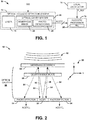
- FIG. 2 illustrates an unclaimed example of an optical acoustic detection system 50.
- the optical acoustic detection system 50 can correspond to the optical acoustic detection system 12 in the example of FIG. 1 . Therefore, reference is to be made to the example of FIG. 1 in the following description of the example of FIG. 2 .
- the optical acoustic detection system 50 includes a VCSEL 52 that is arranged substantially coplanar with a plurality of photodetectors 54.
- the photodetectors 54 can be configured as photodiodes that substantially surround the VCSEL 52 in an approximate X-Z plane, as demonstrated by the Cartesian coordinate system 55.
- the VCSEL 52 is configured to emit an optical beam 56 from an aperture in approximately the direction of the Y-axis, with the optical beam 56 having a linear polarization ( i.e., parallel or perpendicular).
- the optical acoustic detection system 50 also includes a quarter-wave plate 58 in the optical path of the optical beam 56 emitted from the VCSEL 52.
- the quarter-wave plate 58 is therefore configured to provide a quarter-wave retardance to the optical beam 56 convert the optical beam 56 from the linear polarization to a circular polarization.
- the optical acoustic detection system 50 also includes a membranous mirror 60, such as mounted to a housing of the optical microphone system 10 at an input. Therefore, the membranous mirror 60 can vibrate in response to an acoustic input signal AIS.
- the distance along the Y-axis between the VCSEL 52 and the membranous mirror 60 defines an optical cavity 62.
- the optical beam 56 having been converted to the circular polarization by the quarter-wave plate 58, reflects from the membranous mirror 60 back to the quarter-wave plate 58 as a reflected beam 64.
- the quarter-wave plate 58 thus converts the reflected beam 64 back to the linear polarization.
- the linear polarization of the reflected beam 64 is orthogonal to the polarization of the optical beam 56 emitted from the VCSEL 52. Therefore, if the optical beam 56 has a perpendicular polarization, the reflected beam 58 has a parallel polarization, and if the optical beam 56 has a parallel polarization, the reflected beam 58 has a perpendicular polarization.
- the reflected beam 64 is provided back to the VCSEL 52 and to the photodetectors 54.
- the photodetectors 54 are thus configured to monitor an intensity of the reflected beam 64.
- the VCSEL 52 can have a gain medium that includes stimulation axes that are approximately orthogonal with respect to each other. Therefore, upon the reflected beam 64 being provided to the VCSEL 52, the reflected beam 64 begins to stimulate the stimulation axis that corresponds to the polarization of the reflected beam 64, and thus the stimulation axis that is orthogonal with respect to the optical beam 56 that is emitted from the VCSEL 52.
- the VCSEL 52 switches the linear polarization of the optical beam 56 to correspond to the stimulation axis that is stimulated by the reflected beam 64. Therefore, the linear polarization of the reflected beam 64 changes to the orthogonal polarization with respect to the optical beam 56 based on the passing of both the optical beam 56 and the reflected beam 64 through the quarter-wave plate. Accordingly, the VCSEL 52 oscillates between the linear polarizations (e.g., perpendicular and parallel) in providing the optical beam 56.
- the linear polarizations e.g., perpendicular and parallel
- Each of the photodetectors 54 is configured to generate a microphone signal ACSTC, demonstrated as microphone signals ACSTC 1 and ACSTC 2 in the example of FIG. 2 , that correspond to the intensity of the reflected beam 64.
- a microphone signal ACSTC demonstrated as microphone signals ACSTC 1 and ACSTC 2 in the example of FIG. 2 , that correspond to the intensity of the reflected beam 64.
- the microphone signals ACSTC can have a frequency corresponding to the transitions between the linear polarizations based on the intensity drop at each transition.
- FIG. 3 illustrates an example of a timing diagram 100.
- the timing diagram 100 demonstrates an intensity profile of the reflected beam 64 over time, as measured by each of the photodetectors 54, and thus corresponding to the signals ACSTC.
- the reflected beam 64 is provided to the photodetectors 54 at the parallel linear polarization at an intensity I 1 , with the optical beam 56 being provided at the perpendicular polarization.
- the reflected beam 64 stimulates the parallel stimulation axis of the gain medium of the VCSEL 52.
- the VCSEL 52 switches emission of the optical signal 56 from the perpendicular linear polarization to the parallel linear polarization.
- the reflected beam 64 changes to the perpendicular linear polarization.
- the intensity of the reflected beam 64 drops to approximately zero as the VCSEL 52 switches emission of the optical beam 56 from the perpendicular linear polarization to the parallel linear polarization.
- the intensity of the reflected beam 64 increases back to approximately the intensity I 1 .
- the reflected beam 64 stimulates the perpendicular stimulation axis of the gain medium of the VCSEL 52.
- the VCSEL 52 switches emission of the optical signal 56 from the parallel linear polarization to the perpendicular linear polarization. Therefore, the reflected beam 64 changes to the parallel linear polarization.
- the intensity of the reflected beam 64 drops to approximately zero as the VCSEL 52 switches emission of the optical beam 56 from the parallel linear polarization to the perpendicular linear polarization.
- the intensity of the reflected beam 64 increases back to approximately the intensity I 1 .
- the oscillation of the reflected beam between the linear polarizations continues thereafter.
- the optical beam 56 switches from being emitted at the perpendicular linear polarization to the parallel linear polarization at approximately a time T 3 .
- the reflected beam 64 switches from the parallel linear polarization to the perpendicular linear polarization at approximately the time T 3 . Therefore, at approximately the time T 3 , the intensity of the reflected beam 64 drops to approximately zero.
- the microphone signals ACSTC each have a frequency that is based on the oscillation of the reflected beam 64 between the linear polarizations.
- the optical microphone system 10 can therefore be calibrated such that a known stable frequency corresponds to a steady-state ( i.e., absent an acoustic input signal AIS).
- the membranous mirror 60 can vibrate in response to an acoustic input signal, demonstrated diagrammatically at 66 in the example of FIG. 2 .
- an acoustic input signal 66 results in a vibration of the membranous mirror 60 along the Y-axis.
- the length of the optical cavity 62 is modulated at the frequency of the acoustic input signal 66, such that the time that the optical beam 56 and the reflected beam 64 respectively traverse the optical cavity 62 is likewise modulated at the frequency of the acoustic input signal 66.
- the frequency of the oscillations between the linear polarizations of the reflected beam 64, and thus the frequency of the microphone signals ACSTC, is modulated at the frequency of the acoustic input signal 66. Accordingly, the change in frequency of the microphone signals ACSTC can directly correspond to the characteristics (e.g., frequency and amplitude) of the acoustic input signal 66.
- the microphone signals ACSTC 1 and ACSTC 2 are independently generated by the respective photodetectors 54, the microphone signals ACSTC 1 and ACSTC 2 can indicate the characteristics of the acoustic input signal 66 even in the presence of uneven vibration of the membranous mirror 60 across at least one of the X- and Z-axes.
- the reflected beam 64 can be provided to a greater surface area of the photodetector 54 that generates the microphone signal ACSTC 1 than the photodetector 54 that generates the microphone signal ACSTC 2 , or vice-versa.
- the use of the multiple photodetectors 54 can thus provide for a more robust optical microphone system 10, such that the vector components of the acoustic input signal 66 do not have a deleterious impact on the operation of the optical microphone system 10.
- FIG. 2 demonstrates two photodetectors 54, it is to be understood that the optical acoustic detection system 50 could instead include a single photodetector 54, or more than two photodetectors 54. Therefore, the optical acoustic detection system 50 can be configured in any of a variety of ways.
- FIG. 4 illustrates another unclaimed example of an optical acoustic detection system 150.
- the optical acoustic detection system 150 can correspond to the optical acoustic detection system 12 in the example of FIG. 1 . Therefore, reference is to be made to the example of FIG. 1 in the following description of the example of FIG. 4 .
- the optical acoustic detection system 150 is configured substantially similar to the optical acoustic detection system 50 in the example of FIG. 2 .
- the optical acoustic detection system 150 includes a VCSEL 152 that is arranged substantially coplanar with a plurality of photodetectors 154.
- the VCSEL 152 is configured to emit an optical beam 156 from an aperture in approximately the direction of the Y-axis according to a Cartesian coordinate system 155, with the optical beam 156 oscillating between linear polarizations, in the manner described previously in the example of FIG. 2 .
- the optical acoustic detection system 150 includes a quarter-wave plate 158 that converts the linear polarization of the optical beam 156 to the orthogonal linear polarization in a reflected beam 160.
- the optical acoustic detection system 150 further includes a membranous mirror 162 that is mounted to a housing of the optical microphone system 10, with the distance along the Y-axis between the VCSEL 152 and the membranous mirror 162 defining an optical cavity 164.
- the membranous mirror 162 can vibrate in response to an acoustic input signal, demonstrated diagrammatically at 166 in the example of FIG. 4 .
- the optical acoustic detection system 150 includes polarization filters 168 overlaying the photodetectors 154.
- the polarization filters 168 can be configured to filter a specific linear polarization, such that the photodetectors 154 can be prevented from receiving the reflected beam 160 when the reflected beam 160 is being provided at that specific linear polarization. Therefore, the microphone signals ACSTC can have a magnitude of approximately zero during the time when the reflected beam 160 is being provided at that specific linear polarization.
- FIG. 5 illustrates another example of a timing diagram 200.
- the timing diagram 200 demonstrates an intensity profile of the reflected beam 160 over time, as measured by each of the photodetectors 154, and thus corresponding to the signals ACSTC.
- the polarization filters 168 can be configured to filter the perpendicular linear polarization.
- the reflected beam 160 is provided to the photodetectors 154 at the parallel linear polarization at an intensity I 1 , with the optical beam 156 being provided at the perpendicular polarization.
- the reflected beam 160 stimulates the parallel stimulation axis of the gain medium of the VCSEL 152.
- the VCSEL 152 switches emission of the optical signal 156 from the perpendicular linear polarization to the parallel linear polarization. Therefore, the reflected beam 160 changes to the perpendicular linear polarization.
- the intensity of the reflected beam 160 drops to approximately zero as the VCSEL 152 switches emission of the optical beam 156 from the perpendicular linear polarization to the parallel linear polarization.
- the polarization filters 168 filtering the perpendicular linear polarization of the reflected beam 160, the intensity of the reflected beam 160 as measured by the photodetectors 154 remains at approximately zero.
- the reflected beam 160 stimulates the perpendicular stimulation axis of the gain medium of the VCSEL 152.
- the VCSEL 152 switches emission of the optical signal 156 from the parallel linear polarization to the perpendicular linear polarization. Therefore, the reflected beam 160 changes to the parallel linear polarization.
- the intensity of the reflected beam 160 as measured by the photodetectors 154 increases back to approximately the intensity I 1 .
- the optical beam 156 switches from being emitted at the perpendicular linear polarization to the parallel linear polarization at approximately a time T 3 .
- the reflected beam 160 switches from the parallel linear polarization to the perpendicular linear polarization at approximately the time T 3 . Therefore, at approximately the time T 3 , the intensity of the reflected beam 160 drops to approximately zero as measured by the photodetectors 154 and remains at approximately zero until the optical beam 156 is again provided with the perpendicular linear polarization.
- the microphone signals ACSTC each have a frequency that is based on the oscillation of the reflected beam 160 between the linear polarizations.
- the frequency of the microphone signals ACSTC can be more easily measured based on the change in intensity between zero and the intensity I 1 through every other linear polarization change.
- FIG. 6 illustrates an unclaimed example of a top-view of an optical acoustic detection system 250.
- the optical acoustic detection system 250 can correspond to the optical acoustic detection system 50 in the example of FIG. 2 or the optical acoustic detection system 150 in the example of FIG. 4 .
- the optical acoustic detection system 250 includes a VCSEL 252 that includes a substrate 254 and a gain medium with aperture 256.
- the optical acoustic detection system 250 also includes a plurality of photodetectors 258 that substantially surround the VCSEL 252 in an X-Z plane, as demonstrated based on a Cartesian coordinate system 260.
- the VCSEL 252 is configured to emit an optical beam in the +Y direction from the aperture 256.
- the optical beam can thus be reflected back via a membranous mirror to be received as a reflected beam having an orthogonal polarization by the gain medium 256 and the photodetectors 258. Therefore, based on the orthogonal polarization of the reflected beam received at the gain medium 256, the optical beam can oscillate between the orthogonal linear polarizations, as described previously.
- the photodetectors 258 can each be configured to separately generate microphone signals having a frequency that corresponds to acoustic input signal AIS.
- the microphone signals can indicate the magnitude of the acoustic input signal AIS even in the presence of a vector component of the reflected optical beam in at least one of the X- and Z-axes, such as based on a non-uniformity of the membranous mirror.
- the reflected beam can be provided to a greater surface one or more of the photodetectors 258 in the example of FIG. 6 relative to others of the photodetectors 258.
- the optical microphone system in which the optical acoustic detection system 250 is included can be operated in a robust manner, such that the vector components of the acoustic input signal AIS do not have a deleterious impact on the operation of the associated optical microphone system.
- FIG. 7 illustrates an embodiment according to the invention of an optical acoustic detection system 300.
- the optical acoustic detection system 300 can correspond to the optical acoustic detection system 12 in the example of FIG. 1 . Therefore, reference is to be made to the example of FIG. 1 in the following description of the embodiment of FIG. 7 .
- the optical acoustic detection system 300 includes a VCSEL 302 that is configured to emit an optical beam 304 from an aperture in approximately the direction of the Y-axis, as demonstrated by the Cartesian coordinate system 306, with the optical beam 304 having a linear polarization ( i.e., parallel or perpendicular).
- the optical acoustic detection system 300 also includes a first quarter-wave plate 308 in the optical path of the optical beam 304 to convert the optical beam 304 from the linear polarization to a circular polarization.
- the optical acoustic detection system 300 also includes a membranous mirror 310 and an acoustic reflector 312, such as mounted to a housing of the optical microphone system 10 at an input.
- the acoustic reflector 312 can be arranged as a substantially concave structure that substantially surrounds a portion of the optical acoustic detection system 300, and is thus demonstrated in the embodiment of FIG. 7 in a cross-section.
- the acoustic reflector 312 can thus reflect the acoustic input signal, demonstrated at 314, toward the membranous mirror 310. Therefore, the membranous mirror 310 can vibrate in response to the acoustic input signal 314.
- the membranous mirror 310 is configured as a partially-reflective (e.g., 70%-90% reflective) mirror to be reflective of a first portion of the optical beam 304 and to be transmissive of a second portion of the optical beam 304.
- the first portion of the transmitted optical beam 304 having been converted to the circular polarization by the first quarter-wave plate 308, reflects from the membranous mirror 310 back to the first quarter-wave plate 308 as a reflected beam 318.
- the first quarter-wave plate 308 thus converts the reflected beam 318 back to the linear polarization that is orthogonal to the linear polarization of the optical beam 308, such that the VCSEL 302 oscillates between the linear polarizations (e.g., perpendicular and parallel) in providing the optical beam 304, as described previously regarding the example of FIG. 2 .
- the optical acoustic detection system 300 also includes a second quarter-wave plate 320 and a polarizing beamsplitter 322.
- the second quarter-wave plate 320 is located opposite the membranous mirror 310 from the VCSEL 302. As described previously, the membranous mirror 310 is partially-silvered, such that the second portion of the transmitted optical beam 304, having been converted to the circular polarization by the first quarter-wave plate 308, is transmitted through the membranous mirror 310 to the second quarter-wave plate 320 as a transmissive beam 324.
- the second quarter-wave plate 320 can thus convert the optical beam 304 from the circular polarization back to the linear polarization that is orthogonal to the linear polarization of the optical beam 308, such that the transmissive beam 324 oscillates between the first linear polarization and the second linear polarization.
- the polarizing beamsplitter 322 is configured to be transmissive with respect to the first linear polarization of the transmissive beam 324 and to be reflective with respect to the second linear polarization of the transmissive beam 324.
- the first linear polarization of the transmissive beam 324 is provided to a first photodetector 326 and the second linear polarization of the transmissive beam 324 is provided to a second photodetector 328.
- Each of the photodetectors 326 and 328 is configured to generate a microphone signal ACSTC, demonstrated as microphone signals ACST C1 and ACST C2 in the embodiment of FIG. 7 , that correspond to the intensity of the respective first linear polarization of the transmissive beam 324 and second linear polarization of the transmissive beam 324.
- the intensity of a respective one of the first linear polarization of the transmissive beam 324 and second linear polarization of the transmissive beam 324 drops to an approximate zero intensity. Therefore, the microphone signals ACST C1 and ACST C2 can have a frequency corresponding to the transitions between the linear polarizations based on the intensity change at each transition.
- the acoustic processor 16 can be configured to subtract one of the microphone signals ACST C1 and ACST C2 from the other of the microphone signals ACST C1 and ACST C2 to calculate a mathematical difference between the microphone signals ACST C1 and ACST C2 .
- FIG. 8 illustrates an embodiment of a timing diagram 350 according to the invention.
- the timing diagram 350 demonstrates an intensity profile of the transmissive beam 324 over time, as measured by each of the photodetectors 326 and 328, and thus corresponding to the microphone signals ACST C1 and ACST C2 .
- the transmissive beam 324 is provided to the polarizing beamsplitter 322 at the parallel linear polarization at an intensity I 1 , and thus with a perpendicular polarization being intensity zero. Therefore, the polarizing beamsplitter 322 is transmissive of the transmissive beam 324 to provide the transmissive beam 324 to the first photodetector 326.
- the reflected beam 318 stimulates the parallel stimulation axis of the gain medium of the VCSEL 302.
- the VCSEL 302 switches emission of the optical signal 306 from the perpendicular linear polarization to the parallel linear polarization. Therefore, the transmissive beam 324 is provided to the polarizing beamsplitter 322 at the perpendicular linear polarization at an intensity I 1 , and thus with a parallel polarization being intensity zero. Therefore, the polarizing beamsplitter 322 is reflective of the transmissive beam 324 to provide the transmissive beam 324 to the second photodetector 328.
- the reflected beam 318 stimulates the perpendicular stimulation axis of the gain medium of the VCSEL 302.
- the optical beam 304 switches from being emitted at the parallel linear polarization to the perpendicular linear polarization at approximately a time T 2 .
- the transmissive beam 324 switches from the perpendicular linear polarization to the parallel linear polarization at approximately the time T 2 . Therefore, at approximately the time T 2 , the mathematical difference of the first and second linear polarization components of the transmissive beam 324 increases from -I 1 to I 1 .
- mathematical difference of the microphone signals ACST C1 and ACST C2 has a frequency that is based on the oscillation of the transmissive beam 324 between the linear polarizations.
- the optical microphone system 10 can therefore be calibrated such that a known stable frequency corresponds to a steady-state ( i.e., absent an acoustic input signal AIS).
- the differential detection of the transmissive beam 324 allows collection and use of substantially all of the available detection light of the transmissive beam 324, while maintaining the optical detection advantages of the polarization-sensitive detection scheme demonstrated by the optical acoustic detection system 150 in the example of FIG. 4 .
- the fundamental noise limit due to photon shot noise can be substantially reduced by a factor of approximately the square root of two based on collecting approximately twice as much optical energy as the optical acoustic detection system 150 in the example of FIG. 4 .
- the optical acoustic detection system 300 is not intended to be limited to the embodiment of FIG. 7 .
- the acoustic reflector 312 is configured to increase the available acoustic power, thus increasing the amount of the acoustic signal 314 that is incident on the membranous mirror 310 to correspondingly increase the potential sensitivity of the optical acoustic detection system 300 (e.g. to decrease the minimum acoustic signal 314 required for detection).
- the acoustic reflector 312 is not required for operation of the optical acoustic detection system 300.
- acoustic reflector 312 is not demonstrated as being part of the optical acoustic detection systems 50 and 150 in the respective examples of FIGS. 2 and 4 , it is to be understood that the acoustic reflector 312 could be implemented in the optical acoustic detection systems 50 and 150 in the respective examples of FIGS. 2 and 4 to reflect the acoustic signal AIS toward the respective membranous mirrors 60 and 162.
- a given optical acoustic detection system described herein can include photodetectors coupled to a polarizing beamsplitter, such as demonstrated in the embodiment of FIG.
- optical acoustic detection systems described herein can be configured in a variety of ways.
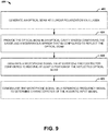
- FIG. 9 a methodology in accordance with various aspects of the present invention will be better appreciated with reference to FIG. 9 . While, for purposes of simplicity of explanation, the methodology of FIG. 9 is shown and described as executing serially, it is to be understood and appreciated that the present invention is not limited by the illustrated order, as some aspects could, in accordance with the present invention, occur in different orders and/or concurrently with other aspects from that shown and described herein. Moreover, not all illustrated features may be required to implement a methodology in accordance with an aspect of the present invention.
- FIG. 9 illustrates an unclaimed example of a method 400 for determining characteristics of an acoustic input signal (e.g., the acoustic input signal AIS).
- an optical beam e.g., the optical beam 56
- a laser e.g., the laser 18
- the optical beam is provided in an optical cavity system (e.g., the optical cavity system 20) comprising the laser and a membranous mirror (e.g., the membranous mirror 22) that is configured to reflect the optical beam.
- an optical cavity system e.g., the optical cavity system 20
- a membranous mirror e.g., the membranous mirror 22
- a microphone signal (e.g., the microphone signal(s) ACSTC) is generated via at least one photodetector (e.g., the photodetector(s) 24) configured to receive at least a portion of the reflected optical beam (e.g., the reflected beams 64).
- the microphone signal can be indicative of vibration of the membranous mirror resulting from the acoustic input signal.
- the microphone signal is demodulated via a reference frequency signal (e.g., the reference signal F_REF) to determine characteristics (e.g., frequency and amplitude) of the acoustic input signal.
- a reference frequency signal e.g., the reference signal F_REF
Landscapes
- Physics & Mathematics (AREA)
- Engineering & Computer Science (AREA)
- Acoustics & Sound (AREA)
- Signal Processing (AREA)
- Electrostatic, Electromagnetic, Magneto- Strictive, And Variable-Resistance Transducers (AREA)
- Measurement Of Mechanical Vibrations Or Ultrasonic Waves (AREA)
Claims (10)
- Système de microphone optique (10) comprenant :un laser (18) conçu pour émettre un faisceau optique (318) à une polarisation linéaire, le laser (18) étant en outre conçu pour faire osciller la polarisation linéaire du faisceau optique entre une première polarisation linéaire et une seconde polarisation linéaire ;un système de cavité optique (20) comprenant un miroir membraneux partiellement argenté (310) qui est conçu pour réfléchir une première partie du faisceau optique (318) et pour laisser passer une seconde partie du faisceau optique (324), et pour vibrer en réaction à un signal d'entrée acoustique (314) ;un séparateur de faisceau polarisant (322) conçu pour séparer la seconde partie du faisceau optique (324) en la première polarisation linéaire et la seconde polarisation linéaire qui est orthogonale par rapport à la première polarisation linéaire ;un premier photodétecteur (326) conçu pour recevoir la première polarisation linéaire de la seconde partie du faisceau optique (324) et pour surveiller l'intensité de la seconde partie du faisceau optique (324) par rapport à la première polarisation linéaire pour générer un premier signal de microphone ;un second photodétecteur (328) conçu pour surveiller une intensité de la seconde partie du faisceau optique (324) par rapport à la seconde polarisation linéaire pour générer un second signal de microphone, les premier et second signaux de microphone étant indicatifs de la vibration du miroir membraneux partiellement argenté (310) résultant du signal d'entrée acoustique (314), dans lequel les premier et second signaux de microphone sont des signaux modulés en fréquence [FM] comprenant un signal de porteuse qui a une fréquence porteuse correspondant à l'oscillation de la polarisation linéaire du faisceau optique et un signal de bande de base correspondant au signal d'entrée acoustique ; etun processeur acoustique (16) conçu pour démoduler les premier et second signaux de microphone par l'intermédiaire d'un signal de fréquence étalon associé au signal de porteuse pour déterminer une amplitude et une fréquence du signal d'entrée acoustique sur la base de la fréquence d'une différence mathématique entre le premier signal de microphone et le second signal de microphone.
- Système (10) selon la revendication 1, dans lequel le système de cavité optique (20) comprend en outre une lame quart d'onde disposée entre le laser (18) et le miroir membraneux et conçue pour convertir le faisceau optique de la première polarisation linéaire en une polarisation circulaire et pour convertir le faisceau optique réfléchi de la polarisation circulaire en la seconde polarisation linéaire.
- Système (10) selon la revendication 2, dans lequel le laser (18) est conçu comme un laser à cavité verticale émettant par la surface (VCSEL) qui est conçu pour osciller entre l'émission du faisceau optique à la première polarisation linéaire et l'émission du faisceau optique à la seconde polarisation linéaire en réaction au VCSEL recevant le signal optique réfléchi.
- Système (10) selon la revendication 3, dans lequel les premier et second signaux de microphone comprennent des transitions périodiques correspondant à une oscillation entre les première et seconde polarisations linéaires du faisceau optique réfléchi, le système comprenant en outre un oscillateur local conçu pour générer un signal de fréquence étalon qui est asservi en phase à une fréquence associée à une fréquence native correspondant aux transitions périodiques entre les première et seconde polarisations linéaires du faisceau optique réfléchi, dans lequel le processeur acoustique est conçu pour démoduler les premier et second signaux de microphone par le signal de fréquence étalon pour déterminer une fréquence des transitions périodiques des premier et second signaux de microphone correspondant à l'amplitude et à la fréquence du signal d'entrée acoustique.
- Système (10) selon la revendication 1, comprenant en outre un oscillateur local conçu pour générer le signal de fréquence étalon qui est asservi en phase à une fréquence associée à des transitions de polarisation linéaires périodiques du faisceau optique à une fréquence de mise à jour qui est inférieure à une fréquence de détection audible minimale du signal d'entrée acoustique par l'intermédiaire d'une boucle à verrouillage de phase, dans lequel le processeur acoustique est conçu pour démoduler les premier et second signaux de microphone par le signal de fréquence étalon pour déterminer l'amplitude et la fréquence du signal d'entrée acoustique.
- Système (10) selon la revendication 1, comprenant en outre un réflecteur acoustique conçu pour réfléchir le signal d'entrée acoustique vers le miroir membraneux.
- Procédé de détermination d'un signal d'entrée acoustique (314), le procédé comprenant :la génération d'un faisceau optique à une polarisation linéaire par l'intermédiaire d'un laser (18), la génération du faisceau optique comprenant la commutation périodique de la polarisation linéaire du faisceau optique entre une première polarisation linéaire et une seconde polarisation linéaire ;la fourniture du faisceau optique dans un système de cavité optique (20) comprenant le laser (18) et un miroir membraneux partiellement argenté (310) qui est conçu pour réfléchir une première partie du faisceau optique (318) et pour laisser passer une seconde partie du faisceau optique (324), et un séparateur de faisceau polarisant (322) conçu pour séparer la seconde partie du faisceau optique (324) en la première polarisation linéaire et la seconde polarisation linéaire qui est orthogonale par rapport à la première polarisation linéaire ;la génération d'un premier signal de microphone par l'intermédiaire d'un premier photodétecteur (326) conçu pour surveiller une intensité de la seconde partie du faisceau optique (324) par rapport à la première polarisation linéaire ;la génération d'un second signal de microphone par l'intermédiaire d'un second photodétecteur (328) conçu pour surveiller une intensité de la seconde partie du faisceau optique (324) par rapport à la seconde polarisation linéaire, les premier et second signaux de microphone étant indicatifs de la vibration du miroir membraneux partiellement argenté (310) résultant du signal d'entrée acoustique (314), dans lequel les premier et second signaux de microphone sont des signaux modulés en fréquence [FM] comprenant un signal de porteuse qui a une fréquence porteuse correspondant à l'oscillation de la polarisation linéaire du faisceau optique et un signal de bande de base correspondant au signal d'entrée acoustique ; etla démodulation des premier et second signaux de microphone dans un processeur acoustique (16) par l'intermédiaire d'un signal de fréquence étalon associé au signal de porteuse pour déterminer une amplitude et une fréquence du signal d'entrée acoustique sur la base de la fréquence d'une différence mathématique entre le premier signal de microphone et le second signal de microphone.
- Système selon la revendication 7, dans lequel la génération des premier et second signaux de microphone comprend la génération des premier et second signaux de microphone de telle sorte que la fréquence des premier et second signaux de microphone repose sur une fréquence de la commutation périodique de la polarisation linéaire du faisceau optique entre la première polarisation linéaire et la seconde polarisation linéaire et qui repose sur la vibration du miroir membraneux résultant du signal d'entrée acoustique.
- Système selon la revendication 8, comprenant en outre la génération du signal de fréquence étalon par l'intermédiaire d'un oscillateur local, le signal de fréquence étalon ayant une fréquence associée à une fréquence native correspondant à la commutation périodique entre les première et seconde polarisations linéaires du faisceau optique, dans lequel la démodulation des premier et second signaux de microphone comprend la démodulation des premier et second signaux de microphone par l'intermédiaire du signal de fréquence étalon pour supprimer un signal de porteuse associé à la commutation périodique entre les première et seconde polarisations linéaires du faisceau optique des premier et second signaux de microphone.
- Système selon la revendication 7, comprenant en outre le verrouillage de phase du signal de fréquence étalon à une fréquence associée aux transitions périodiques de polarisation linéaire du faisceau optique à une fréquence de mise à jour qui est inférieure à une fréquence de détection audible minimale du signal d'entrée acoustique.
Applications Claiming Priority (1)
| Application Number | Priority Date | Filing Date | Title |
|---|---|---|---|
| US15/081,043 US9992581B2 (en) | 2016-03-25 | 2016-03-25 | Optical microphone system |
Publications (2)
| Publication Number | Publication Date |
|---|---|
| EP3223540A1 EP3223540A1 (fr) | 2017-09-27 |
| EP3223540B1 true EP3223540B1 (fr) | 2021-09-08 |
Family
ID=58314141
Family Applications (1)
| Application Number | Title | Priority Date | Filing Date |
|---|---|---|---|
| EP17160682.5A Active EP3223540B1 (fr) | 2016-03-25 | 2017-03-13 | Système de microphone optique |
Country Status (4)
| Country | Link |
|---|---|
| US (1) | US9992581B2 (fr) |
| EP (1) | EP3223540B1 (fr) |
| JP (1) | JP6502410B2 (fr) |
| CA (1) | CA2961240C (fr) |
Families Citing this family (7)
| Publication number | Priority date | Publication date | Assignee | Title |
|---|---|---|---|---|
| CN108827448B (zh) * | 2018-07-28 | 2023-09-26 | 天津大学 | 基于平面反光镜和光电阵列的振动及倾角测量系统及方法 |
| DE112020002083T5 (de) * | 2019-04-23 | 2022-02-17 | Ams Ag | Mobiles kommunikationsgerät ohne physische bildschirmöffnung für audio |
| US11684271B2 (en) * | 2020-03-05 | 2023-06-27 | Welch Allyn, Inc. | Wearable device for sensing vital signs |
| US20230308811A1 (en) * | 2020-07-06 | 2023-09-28 | Sony Group Corporation | Optical microphone and information processing apparatus |
| US20220120945A1 (en) * | 2020-10-16 | 2022-04-21 | GM Global Technology Operations LLC | Feedback sensor for mems mirror |
| US20230018486A1 (en) * | 2021-07-19 | 2023-01-19 | Northrop Grumman Systems Corporation | Optical proximity system |
| US20240107239A1 (en) * | 2022-09-26 | 2024-03-28 | Aac Acoustic Technologies (Shenzhen) Co., Ltd. | Mems optical microphone |
Family Cites Families (22)
| Publication number | Priority date | Publication date | Assignee | Title |
|---|---|---|---|---|
| JPH01214719A (ja) | 1988-02-24 | 1989-08-29 | Hitachi Constr Mach Co Ltd | 光音響波の集音装置 |
| JPH01231500A (ja) | 1988-03-11 | 1989-09-14 | Nikou Kogaku Kk | 光マイクロフォン |
| JPH05215764A (ja) | 1992-01-31 | 1993-08-24 | Canon Inc | 光学式加速度計及び光学式角加速度計 |
| US7134343B2 (en) | 2003-07-25 | 2006-11-14 | Kabushiki Kaisha Toshiba | Opto-acoustoelectric device and methods for analyzing mechanical vibration and sound |
| JP4071730B2 (ja) | 2004-03-26 | 2008-04-02 | 株式会社東芝 | 振動解析装置及び振動解析方法 |
| DE102005013833B3 (de) | 2005-03-24 | 2006-06-14 | Siemens Audiologische Technik Gmbh | Hörhilfevorrichtung mit optischem Mikrofon |
| US7355720B1 (en) | 2005-12-20 | 2008-04-08 | Sandia Corporation | Optical displacement sensor |
| US7826629B2 (en) | 2006-01-19 | 2010-11-02 | State University New York | Optical sensing in a directional MEMS microphone |
| US7359067B2 (en) | 2006-04-07 | 2008-04-15 | Symphony Acoustics, Inc. | Optical displacement sensor comprising a wavelength-tunable optical source |
| JP4264667B2 (ja) | 2007-02-16 | 2009-05-20 | ソニー株式会社 | 振動検出装置 |
| JP2008202959A (ja) | 2007-02-16 | 2008-09-04 | Sony Corp | 振動検出装置 |
| JP2009146545A (ja) | 2007-12-17 | 2009-07-02 | Sony Corp | 光ディスク装置、利得設定方法、およびプログラム |
| EP2338287B1 (fr) * | 2008-09-12 | 2013-07-03 | Knowles Electronics Asia PTE. Ltd. | Système transducteur |
| US8072609B1 (en) | 2008-12-30 | 2011-12-06 | The United States Of America As Represented By The Secretary Of The Army | Enhanced sensitivity vibrometer |
| US20120143018A1 (en) | 2009-01-19 | 2012-06-07 | Skidmore Frank M | Portable touchless vital sign acquisition device |
| CN101482575B (zh) | 2009-02-23 | 2011-02-09 | 东南大学 | 一种悬臂梁结构的谐振式集成光波导加速度计 |
| CA2793452C (fr) | 2010-03-15 | 2018-09-11 | The Board Of Trustees Of The Leland Stanford Junior University | Capteur acoustique compatible avec une fibre optique |
| WO2012029236A1 (fr) | 2010-08-31 | 2012-03-08 | パナソニック株式会社 | Microphone optique |
| EP2646862B1 (fr) | 2010-12-02 | 2020-09-23 | Ofs Fitel Llc | Capteur courbe de laser à fibre dfb et microphone hétérodyne optique |
| CN103222282A (zh) | 2011-04-05 | 2013-07-24 | 松下电器产业株式会社 | 光学麦克风 |
| JP5926456B2 (ja) | 2012-06-06 | 2016-05-25 | ノースロップ グルマン システムズ コーポレーションNorthrop Grumman Systems Corporation | 光学式加速度計システム |
| US9157856B2 (en) | 2012-09-10 | 2015-10-13 | Yunbo Guo | Integrated photonic crystal structures and their applications |
-
2016
- 2016-03-25 US US15/081,043 patent/US9992581B2/en active Active
-
2017
- 2017-03-13 EP EP17160682.5A patent/EP3223540B1/fr active Active
- 2017-03-20 CA CA2961240A patent/CA2961240C/fr active Active
- 2017-03-24 JP JP2017058770A patent/JP6502410B2/ja active Active
Also Published As
| Publication number | Publication date |
|---|---|
| JP6502410B2 (ja) | 2019-04-17 |
| US9992581B2 (en) | 2018-06-05 |
| CA2961240A1 (fr) | 2017-09-25 |
| CA2961240C (fr) | 2020-07-21 |
| US20170280252A1 (en) | 2017-09-28 |
| JP2017175622A (ja) | 2017-09-28 |
| EP3223540A1 (fr) | 2017-09-27 |
Similar Documents
| Publication | Publication Date | Title |
|---|---|---|
| EP3223540B1 (fr) | Système de microphone optique | |
| US10215816B2 (en) | Magnetic field measuring apparatus | |
| EP2710335B1 (fr) | Capteur optique | |
| US7970032B2 (en) | Method and device for reducing laser phase noise | |
| US11733027B2 (en) | Laser interferometer | |
| JP2016014662A (ja) | 対称三レーザ共振器光ファイバジャイロスコープ | |
| CA2491700A1 (fr) | Laser a semiconducteurs stabilise offrant une haute coherence de frequence | |
| JP2012244182A (ja) | 周波数安定化レーザー・システム | |
| US8264284B2 (en) | Atomic frequency acquisition device based on self-mixing interference | |
| US20220065612A1 (en) | Laser Interferometer | |
| CN114964352A (zh) | 激光干涉仪 | |
| JP3081253B2 (ja) | 光学検出器 | |
| US6801324B1 (en) | Interferometer control and laser frequency locking | |
| JP2022038678A (ja) | レーザー干渉計 | |
| CN114175683B (zh) | 用于测量位移的光学换能器及方法 | |
| JP2937418B2 (ja) | 半導体レーザ装置 | |
| KR20190021892A (ko) | 광센서 | |
| JP2715484B2 (ja) | 半導体レーザ装置 | |
| US20230085489A1 (en) | Laser Interferometer | |
| JPH067099B2 (ja) | チューナブルエタロンを用いたガスセンサ | |
| JP3451230B2 (ja) | 共振型光ファイバジャイロ | |
| JPH1065265A (ja) | レーザダイオードモジュールおよびモードホップ検出装置 | |
| CN115876303A (zh) | 激光干涉仪 | |
| JP2003224319A (ja) | レーザ光発生装置及び方法 | |
| JPS63233585A (ja) | レ−ザ光源 |
Legal Events
| Date | Code | Title | Description |
|---|---|---|---|
| PUAI | Public reference made under article 153(3) epc to a published international application that has entered the european phase |
Free format text: ORIGINAL CODE: 0009012 |
|
| STAA | Information on the status of an ep patent application or granted ep patent |
Free format text: STATUS: REQUEST FOR EXAMINATION WAS MADE |
|
| 17P | Request for examination filed |
Effective date: 20170313 |
|
| AK | Designated contracting states |
Kind code of ref document: A1 Designated state(s): AL AT BE BG CH CY CZ DE DK EE ES FI FR GB GR HR HU IE IS IT LI LT LU LV MC MK MT NL NO PL PT RO RS SE SI SK SM TR |
|
| AX | Request for extension of the european patent |
Extension state: BA ME |
|
| STAA | Information on the status of an ep patent application or granted ep patent |
Free format text: STATUS: EXAMINATION IS IN PROGRESS |
|
| 17Q | First examination report despatched |
Effective date: 20181025 |
|
| STAA | Information on the status of an ep patent application or granted ep patent |
Free format text: STATUS: EXAMINATION IS IN PROGRESS |
|
| GRAP | Despatch of communication of intention to grant a patent |
Free format text: ORIGINAL CODE: EPIDOSNIGR1 |
|
| STAA | Information on the status of an ep patent application or granted ep patent |
Free format text: STATUS: GRANT OF PATENT IS INTENDED |
|
| INTG | Intention to grant announced |
Effective date: 20210601 |
|
| GRAS | Grant fee paid |
Free format text: ORIGINAL CODE: EPIDOSNIGR3 |
|
| GRAA | (expected) grant |
Free format text: ORIGINAL CODE: 0009210 |
|
| STAA | Information on the status of an ep patent application or granted ep patent |
Free format text: STATUS: THE PATENT HAS BEEN GRANTED |
|
| AK | Designated contracting states |
Kind code of ref document: B1 Designated state(s): AL AT BE BG CH CY CZ DE DK EE ES FI FR GB GR HR HU IE IS IT LI LT LU LV MC MK MT NL NO PL PT RO RS SE SI SK SM TR |
|
| REG | Reference to a national code |
Ref country code: GB Ref legal event code: FG4D |
|
| REG | Reference to a national code |
Ref country code: CH Ref legal event code: EP Ref country code: AT Ref legal event code: REF Ref document number: 1429662 Country of ref document: AT Kind code of ref document: T Effective date: 20210915 |
|
| REG | Reference to a national code |
Ref country code: DE Ref legal event code: R096 Ref document number: 602017045535 Country of ref document: DE |
|
| REG | Reference to a national code |
Ref country code: IE Ref legal event code: FG4D |
|
| REG | Reference to a national code |
Ref country code: LT Ref legal event code: MG9D |
|
| REG | Reference to a national code |
Ref country code: NL Ref legal event code: MP Effective date: 20210908 |
|
| PG25 | Lapsed in a contracting state [announced via postgrant information from national office to epo] |
Ref country code: LT Free format text: LAPSE BECAUSE OF FAILURE TO SUBMIT A TRANSLATION OF THE DESCRIPTION OR TO PAY THE FEE WITHIN THE PRESCRIBED TIME-LIMIT Effective date: 20210908 Ref country code: BG Free format text: LAPSE BECAUSE OF FAILURE TO SUBMIT A TRANSLATION OF THE DESCRIPTION OR TO PAY THE FEE WITHIN THE PRESCRIBED TIME-LIMIT Effective date: 20211208 Ref country code: HR Free format text: LAPSE BECAUSE OF FAILURE TO SUBMIT A TRANSLATION OF THE DESCRIPTION OR TO PAY THE FEE WITHIN THE PRESCRIBED TIME-LIMIT Effective date: 20210908 Ref country code: ES Free format text: LAPSE BECAUSE OF FAILURE TO SUBMIT A TRANSLATION OF THE DESCRIPTION OR TO PAY THE FEE WITHIN THE PRESCRIBED TIME-LIMIT Effective date: 20210908 Ref country code: FI Free format text: LAPSE BECAUSE OF FAILURE TO SUBMIT A TRANSLATION OF THE DESCRIPTION OR TO PAY THE FEE WITHIN THE PRESCRIBED TIME-LIMIT Effective date: 20210908 Ref country code: NO Free format text: LAPSE BECAUSE OF FAILURE TO SUBMIT A TRANSLATION OF THE DESCRIPTION OR TO PAY THE FEE WITHIN THE PRESCRIBED TIME-LIMIT Effective date: 20211208 Ref country code: SE Free format text: LAPSE BECAUSE OF FAILURE TO SUBMIT A TRANSLATION OF THE DESCRIPTION OR TO PAY THE FEE WITHIN THE PRESCRIBED TIME-LIMIT Effective date: 20210908 Ref country code: RS Free format text: LAPSE BECAUSE OF FAILURE TO SUBMIT A TRANSLATION OF THE DESCRIPTION OR TO PAY THE FEE WITHIN THE PRESCRIBED TIME-LIMIT Effective date: 20210908 |
|
| REG | Reference to a national code |
Ref country code: AT Ref legal event code: MK05 Ref document number: 1429662 Country of ref document: AT Kind code of ref document: T Effective date: 20210908 |
|
| PG25 | Lapsed in a contracting state [announced via postgrant information from national office to epo] |
Ref country code: LV Free format text: LAPSE BECAUSE OF FAILURE TO SUBMIT A TRANSLATION OF THE DESCRIPTION OR TO PAY THE FEE WITHIN THE PRESCRIBED TIME-LIMIT Effective date: 20210908 Ref country code: GR Free format text: LAPSE BECAUSE OF FAILURE TO SUBMIT A TRANSLATION OF THE DESCRIPTION OR TO PAY THE FEE WITHIN THE PRESCRIBED TIME-LIMIT Effective date: 20211209 |
|
| PG25 | Lapsed in a contracting state [announced via postgrant information from national office to epo] |
Ref country code: AT Free format text: LAPSE BECAUSE OF FAILURE TO SUBMIT A TRANSLATION OF THE DESCRIPTION OR TO PAY THE FEE WITHIN THE PRESCRIBED TIME-LIMIT Effective date: 20210908 |
|
| PG25 | Lapsed in a contracting state [announced via postgrant information from national office to epo] |
Ref country code: IS Free format text: LAPSE BECAUSE OF FAILURE TO SUBMIT A TRANSLATION OF THE DESCRIPTION OR TO PAY THE FEE WITHIN THE PRESCRIBED TIME-LIMIT Effective date: 20220108 Ref country code: SM Free format text: LAPSE BECAUSE OF FAILURE TO SUBMIT A TRANSLATION OF THE DESCRIPTION OR TO PAY THE FEE WITHIN THE PRESCRIBED TIME-LIMIT Effective date: 20210908 Ref country code: SK Free format text: LAPSE BECAUSE OF FAILURE TO SUBMIT A TRANSLATION OF THE DESCRIPTION OR TO PAY THE FEE WITHIN THE PRESCRIBED TIME-LIMIT Effective date: 20210908 Ref country code: RO Free format text: LAPSE BECAUSE OF FAILURE TO SUBMIT A TRANSLATION OF THE DESCRIPTION OR TO PAY THE FEE WITHIN THE PRESCRIBED TIME-LIMIT Effective date: 20210908 Ref country code: PT Free format text: LAPSE BECAUSE OF FAILURE TO SUBMIT A TRANSLATION OF THE DESCRIPTION OR TO PAY THE FEE WITHIN THE PRESCRIBED TIME-LIMIT Effective date: 20220110 Ref country code: PL Free format text: LAPSE BECAUSE OF FAILURE TO SUBMIT A TRANSLATION OF THE DESCRIPTION OR TO PAY THE FEE WITHIN THE PRESCRIBED TIME-LIMIT Effective date: 20210908 Ref country code: NL Free format text: LAPSE BECAUSE OF FAILURE TO SUBMIT A TRANSLATION OF THE DESCRIPTION OR TO PAY THE FEE WITHIN THE PRESCRIBED TIME-LIMIT Effective date: 20210908 Ref country code: EE Free format text: LAPSE BECAUSE OF FAILURE TO SUBMIT A TRANSLATION OF THE DESCRIPTION OR TO PAY THE FEE WITHIN THE PRESCRIBED TIME-LIMIT Effective date: 20210908 Ref country code: CZ Free format text: LAPSE BECAUSE OF FAILURE TO SUBMIT A TRANSLATION OF THE DESCRIPTION OR TO PAY THE FEE WITHIN THE PRESCRIBED TIME-LIMIT Effective date: 20210908 Ref country code: AL Free format text: LAPSE BECAUSE OF FAILURE TO SUBMIT A TRANSLATION OF THE DESCRIPTION OR TO PAY THE FEE WITHIN THE PRESCRIBED TIME-LIMIT Effective date: 20210908 |
|
| REG | Reference to a national code |
Ref country code: DE Ref legal event code: R097 Ref document number: 602017045535 Country of ref document: DE |
|
| PLBE | No opposition filed within time limit |
Free format text: ORIGINAL CODE: 0009261 |
|
| STAA | Information on the status of an ep patent application or granted ep patent |
Free format text: STATUS: NO OPPOSITION FILED WITHIN TIME LIMIT |
|
| PG25 | Lapsed in a contracting state [announced via postgrant information from national office to epo] |
Ref country code: DK Free format text: LAPSE BECAUSE OF FAILURE TO SUBMIT A TRANSLATION OF THE DESCRIPTION OR TO PAY THE FEE WITHIN THE PRESCRIBED TIME-LIMIT Effective date: 20210908 |
|
| 26N | No opposition filed |
Effective date: 20220609 |
|
| PG25 | Lapsed in a contracting state [announced via postgrant information from national office to epo] |
Ref country code: SI Free format text: LAPSE BECAUSE OF FAILURE TO SUBMIT A TRANSLATION OF THE DESCRIPTION OR TO PAY THE FEE WITHIN THE PRESCRIBED TIME-LIMIT Effective date: 20210908 |
|
| PG25 | Lapsed in a contracting state [announced via postgrant information from national office to epo] |
Ref country code: MC Free format text: LAPSE BECAUSE OF FAILURE TO SUBMIT A TRANSLATION OF THE DESCRIPTION OR TO PAY THE FEE WITHIN THE PRESCRIBED TIME-LIMIT Effective date: 20210908 |
|
| REG | Reference to a national code |
Ref country code: CH Ref legal event code: PL |
|
| REG | Reference to a national code |
Ref country code: BE Ref legal event code: MM Effective date: 20220331 |
|
| PG25 | Lapsed in a contracting state [announced via postgrant information from national office to epo] |
Ref country code: LU Free format text: LAPSE BECAUSE OF NON-PAYMENT OF DUE FEES Effective date: 20220313 Ref country code: LI Free format text: LAPSE BECAUSE OF NON-PAYMENT OF DUE FEES Effective date: 20220331 Ref country code: IE Free format text: LAPSE BECAUSE OF NON-PAYMENT OF DUE FEES Effective date: 20220313 Ref country code: CH Free format text: LAPSE BECAUSE OF NON-PAYMENT OF DUE FEES Effective date: 20220331 |
|
| PG25 | Lapsed in a contracting state [announced via postgrant information from national office to epo] |
Ref country code: BE Free format text: LAPSE BECAUSE OF NON-PAYMENT OF DUE FEES Effective date: 20220331 |
|
| P01 | Opt-out of the competence of the unified patent court (upc) registered |
Effective date: 20230607 |
|
| PG25 | Lapsed in a contracting state [announced via postgrant information from national office to epo] |
Ref country code: HU Free format text: LAPSE BECAUSE OF FAILURE TO SUBMIT A TRANSLATION OF THE DESCRIPTION OR TO PAY THE FEE WITHIN THE PRESCRIBED TIME-LIMIT; INVALID AB INITIO Effective date: 20170313 |
|
| PG25 | Lapsed in a contracting state [announced via postgrant information from national office to epo] |
Ref country code: MK Free format text: LAPSE BECAUSE OF FAILURE TO SUBMIT A TRANSLATION OF THE DESCRIPTION OR TO PAY THE FEE WITHIN THE PRESCRIBED TIME-LIMIT Effective date: 20210908 Ref country code: CY Free format text: LAPSE BECAUSE OF FAILURE TO SUBMIT A TRANSLATION OF THE DESCRIPTION OR TO PAY THE FEE WITHIN THE PRESCRIBED TIME-LIMIT Effective date: 20210908 |
|
| PGFP | Annual fee paid to national office [announced via postgrant information from national office to epo] |
Ref country code: DE Payment date: 20240320 Year of fee payment: 8 Ref country code: GB Payment date: 20240320 Year of fee payment: 8 |
|
| PGFP | Annual fee paid to national office [announced via postgrant information from national office to epo] |
Ref country code: IT Payment date: 20240329 Year of fee payment: 8 Ref country code: FR Payment date: 20240328 Year of fee payment: 8 |
|
| PG25 | Lapsed in a contracting state [announced via postgrant information from national office to epo] |
Ref country code: MT Free format text: LAPSE BECAUSE OF FAILURE TO SUBMIT A TRANSLATION OF THE DESCRIPTION OR TO PAY THE FEE WITHIN THE PRESCRIBED TIME-LIMIT Effective date: 20210908 |