EP3222489B1 - System zur schätzung der eisenbahnbodenanlagenverschlechterung und verfahren dafür - Google Patents
System zur schätzung der eisenbahnbodenanlagenverschlechterung und verfahren dafür Download PDFInfo
- Publication number
- EP3222489B1 EP3222489B1 EP15861470.1A EP15861470A EP3222489B1 EP 3222489 B1 EP3222489 B1 EP 3222489B1 EP 15861470 A EP15861470 A EP 15861470A EP 3222489 B1 EP3222489 B1 EP 3222489B1
- Authority
- EP
- European Patent Office
- Prior art keywords
- equipment
- information
- railroad
- train
- section
- Prior art date
- Legal status (The legal status is an assumption and is not a legal conclusion. Google has not performed a legal analysis and makes no representation as to the accuracy of the status listed.)
- Active
Links
Images







Classifications
-
- B—PERFORMING OPERATIONS; TRANSPORTING
- B61—RAILWAYS
- B61L—GUIDING RAILWAY TRAFFIC; ENSURING THE SAFETY OF RAILWAY TRAFFIC
- B61L23/00—Control, warning or like safety means along the route or between vehicles or trains
- B61L23/04—Control, warning or like safety means along the route or between vehicles or trains for monitoring the mechanical state of the route
-
- B—PERFORMING OPERATIONS; TRANSPORTING
- B61—RAILWAYS
- B61L—GUIDING RAILWAY TRAFFIC; ENSURING THE SAFETY OF RAILWAY TRAFFIC
- B61L1/00—Devices along the route controlled by interaction with the vehicle or train
- B61L1/18—Railway track circuits
-
- B—PERFORMING OPERATIONS; TRANSPORTING
- B61—RAILWAYS
- B61L—GUIDING RAILWAY TRAFFIC; ENSURING THE SAFETY OF RAILWAY TRAFFIC
- B61L27/00—Central railway traffic control systems; Trackside control; Communication systems specially adapted therefor
- B61L27/10—Operations, e.g. scheduling or time tables
-
- B—PERFORMING OPERATIONS; TRANSPORTING
- B61—RAILWAYS
- B61L—GUIDING RAILWAY TRAFFIC; ENSURING THE SAFETY OF RAILWAY TRAFFIC
- B61L27/00—Central railway traffic control systems; Trackside control; Communication systems specially adapted therefor
- B61L27/50—Trackside diagnosis or maintenance, e.g. software upgrades
- B61L27/53—Trackside diagnosis or maintenance, e.g. software upgrades for trackside elements or systems, e.g. trackside supervision of trackside control system conditions
-
- B—PERFORMING OPERATIONS; TRANSPORTING
- B61—RAILWAYS
- B61L—GUIDING RAILWAY TRAFFIC; ENSURING THE SAFETY OF RAILWAY TRAFFIC
- B61L27/00—Central railway traffic control systems; Trackside control; Communication systems specially adapted therefor
- B61L27/60—Testing or simulation
-
- G—PHYSICS
- G05—CONTROLLING; REGULATING
- G05B—CONTROL OR REGULATING SYSTEMS IN GENERAL; FUNCTIONAL ELEMENTS OF SUCH SYSTEMS; MONITORING OR TESTING ARRANGEMENTS FOR SUCH SYSTEMS OR ELEMENTS
- G05B23/00—Testing or monitoring of control systems or parts thereof
- G05B23/02—Electric testing or monitoring
-
- G—PHYSICS
- G06—COMPUTING OR CALCULATING; COUNTING
- G06F—ELECTRIC DIGITAL DATA PROCESSING
- G06F30/00—Computer-aided design [CAD]
- G06F30/20—Design optimisation, verification or simulation
-
- B—PERFORMING OPERATIONS; TRANSPORTING
- B61—RAILWAYS
- B61L—GUIDING RAILWAY TRAFFIC; ENSURING THE SAFETY OF RAILWAY TRAFFIC
- B61L25/00—Recording or indicating positions or identities of vehicles or trains or setting of track apparatus
- B61L25/02—Indicating or recording positions or identities of vehicles or trains
- B61L25/021—Measuring and recording of train speed
-
- B—PERFORMING OPERATIONS; TRANSPORTING
- B61—RAILWAYS
- B61L—GUIDING RAILWAY TRAFFIC; ENSURING THE SAFETY OF RAILWAY TRAFFIC
- B61L25/00—Recording or indicating positions or identities of vehicles or trains or setting of track apparatus
- B61L25/02—Indicating or recording positions or identities of vehicles or trains
- B61L25/04—Indicating or recording train identities
-
- B—PERFORMING OPERATIONS; TRANSPORTING
- B61—RAILWAYS
- B61L—GUIDING RAILWAY TRAFFIC; ENSURING THE SAFETY OF RAILWAY TRAFFIC
- B61L29/00—Safety means for rail/road crossing traffic
- B61L29/08—Operation of gates; Combined operation of gates and signals
-
- G—PHYSICS
- G05—CONTROLLING; REGULATING
- G05B—CONTROL OR REGULATING SYSTEMS IN GENERAL; FUNCTIONAL ELEMENTS OF SUCH SYSTEMS; MONITORING OR TESTING ARRANGEMENTS FOR SUCH SYSTEMS OR ELEMENTS
- G05B13/00—Adaptive control systems, i.e. systems automatically adjusting themselves to have a performance which is optimum according to some preassigned criterion
- G05B13/02—Adaptive control systems, i.e. systems automatically adjusting themselves to have a performance which is optimum according to some preassigned criterion electric
- G05B13/0265—Adaptive control systems, i.e. systems automatically adjusting themselves to have a performance which is optimum according to some preassigned criterion electric the criterion being a learning criterion
-
- G—PHYSICS
- G05—CONTROLLING; REGULATING
- G05B—CONTROL OR REGULATING SYSTEMS IN GENERAL; FUNCTIONAL ELEMENTS OF SUCH SYSTEMS; MONITORING OR TESTING ARRANGEMENTS FOR SUCH SYSTEMS OR ELEMENTS
- G05B13/00—Adaptive control systems, i.e. systems automatically adjusting themselves to have a performance which is optimum according to some preassigned criterion
- G05B13/02—Adaptive control systems, i.e. systems automatically adjusting themselves to have a performance which is optimum according to some preassigned criterion electric
- G05B13/04—Adaptive control systems, i.e. systems automatically adjusting themselves to have a performance which is optimum according to some preassigned criterion electric involving the use of models or simulators
Definitions
- the present invention relates to a maintenance system of railroad ground equipment, and in particular relates to a degradation estimation system of railroad ground equipment for estimating the degradation of railroad ground equipment, as well as to the method thereof.
- An equipment maintenance system of railroad ground equipment is a system which supports the monitoring, inspection and replacement of ground equipment for enabling the smooth performance of railroad services.
- signal-related equipment include, for instance, signals, points, alarms, and crossing gates
- railroad track-related equipment include, for instance, rails, ties and railroad switches
- power-related equipment include, for instance, feeder lines and trolley lines.
- PTL 1 describes a method which enables the remote determination of whether or not a point is normal or abnormal by taking the history of the operation condition of the point, separating sound operation data from unsound operation data, and estimating whether the current point operation data corresponds to sound operation data or unsound operation data.
- NPTL 1 describes a system which enables the detection of an abnormality of the railroad track by mounting sensors on an operating vehicle.
- PTL 2 relates to a process for modelling a railway system, which comprises the steps of obtaining timetable data, data on a first parameter that is an input required for train movement and combining the two to produce an output so as to model the parameter as a function of the state of the train for each section of the rail network at any given time.
- NPTL 1 is able to detect an abnormality of the railroad track, it is difficult to deal with other ground equipment with NPTL 1. For example, since crossing gates and points are operated before or after the operating vehicle is run, it is difficult to observe crossing gates and points from the operating vehicle. In order to prevent the occurrence of an abnormality in equipment and reduce the maintenance cost, it is necessary to perform preventive replacement in more ground equipment at a proper timing.
- An object of the present invention is to provide a degradation estimation system of railroad ground equipment capable of estimating the degradation of equipment by simulating the operation mode of such equipment, as well as to provide a method thereof.
- the present invention comprises a degradation estimation system as defined in claim 1 and a degradation estimation method as defined in claim 8.
- an operation mode of track circuit-related equipment disposed on each track circuit of a corresponding railroad section is simulated based on corresponding railroad section timetable information for managing a timetable of a plurality of trains running on a corresponding railroad section, an operating quantity of each track circuit-related equipment is aggregated from the simulation result, and a degradation of each track circuit-related equipment is estimated from the aggregation result.
- Fig. 1 is a configuration diagram showing the first embodiment of the degradation estimation system of railroad ground equipment according to the present invention.
- the degradation estimation system of railroad ground equipment is configured from a computer device comprising information processing resources such as a processor (CPU), an I/O interface, a storage device (for instance, a memory and an HDD), a display device (for instance, a liquid crystal display device) and a bus which mutually connects the foregoing components, and a terminal device which inputs various types of information, for example, corresponding railroad section timetable information 101 and peripheral railroad section timetable information 104, is connected to the I/O interface.
- information processing resources such as a processor (CPU), an I/O interface, a storage device (for instance, a memory and an HDD), a display device (for instance, a liquid crystal display device) and a bus which mutually connects the foregoing components, and a terminal device which inputs various types of information, for example, corresponding railroad section timetable information 101 and peripheral railroad section timetable information 104,
- the processor functions as an execution unit which executes simulation processing according to a simulation program stored in the memory.
- the memory stores a processing unit which simulates an operation mode of equipment disposed on a corresponding railroad section at each set-up timing based on corresponding railroad section timetable information for managing a timetable of a plurality of trains running on the corresponding railroad section to be simulated, and processes the respective simulation results, and an estimation unit which aggregates the respective processing results of the processing unit, as well as one or more computer programs.
- the memory stores, as the processing unit, a related timetable extraction unit 102, a train dynamic simulation unit 105, an on-rail section simulation unit 107, a track circuit simulation unit 109, and a track circuit-related equipment operation simulation unit 110, and stores, as the estimation unit, a track circuit-related equipment operation aggregation unit 112 and an operation output unit 114.
- the processor (CPU) executing the computer programs (for instance, simulation programs) stored in the memory
- the related timetable extraction unit 102 the train dynamic simulation unit 105, the on-rail section simulation unit 107, the track circuit simulation unit 109, the track circuit-related equipment operation simulation unit 110, the track circuit-related equipment operation aggregation unit 112 and the operation output unit 114 are able to exhibit their respective functions (their function as a program).
- the HDD (Hard Disk Drive) stores railroad section information 103, peripheral railroad section timetable information 104, a running curve 106, railroad track information 108, equipment information 111, operation acquisition information 113, and equipment update information 135. Note that the HDD may also store information input from the terminal device, such as the corresponding railroad section timetable information 101 and the peripheral railroad section timetable information 104.
- track circuit-related equipment refers to equipment in which its operation is determined based on the operation of the track circuit (designation of blocking or the like), and, for instance, considered may be signals and crossing gates.
- the related timetable extraction unit 102 refers to the railroad section information 103 and the peripheral railroad section timetable information 104 based on the input corresponding railroad section timetable information 101, and extracts a related timetable of a railroad section (related timetable information) pertaining to the corresponding railroad section.
- a related timetable refers to a timetable of a railroad section that is impacted from factors other than a corresponding timetable from the perspective of ground equipment.
- the train dynamic simulation unit 105 refers to the running curve 106, and simulates the service of each train listed in the corresponding timetable and the peripheral railroad section timetable extracted by the related timetable extraction unit 102 based on information registered in the running curve 106.
- the on-rail section simulation unit 107 refers to the railroad track information 108 for comprehending the on-rail section, and generates on-rail section information at each point in time based on a dynamic obtained in the simulation of the train dynamic simulation unit 105. For example, the on-rail section simulation unit 107 generates on-rail section information regarding on which track circuit a certain train exists at each point in time.
- the track circuit simulation unit 109 simulates an operation of the track circuit based on the on-rail section information generated by the on-rail section simulation unit 107, and the railroad track information 108. Specifically, the track circuit simulation unit 109 determines a state of adjacent track circuits based on a train interval control system according to the on-rail section information. For example, when the train interval control system is a system where the two rearward track circuits are blocked, blocking is set to the on-rail section and the two rearward track circuits of the on-rail section.
- the track circuit simulation unit 109 can simulate the state of the track circuits according to the on-rail condition of each train listed in the timetable of the corresponding railroad section and the peripheral railroad section.
- the track circuit-related equipment operation simulation unit 110 refers to a simulation result of the track circuit simulation unit 109, and the equipment information 111, and simulates an operation of the track circuit-related equipment based on the state of each track circuit, and the equipment information 111.
- the track circuit-related equipment existing in each track circuit can be comprehended from the simulation result.
- the track circuit-related equipment operation simulation unit 110 can determine the operation of each track circuit-related equipment based on the blocked state. For example, a signal will flash in red when the on-rail section is blocked. Note that these track circuit-related equipment are controlled based on a train interval control system designated in each railroad section.
- the track circuit-related equipment operation aggregation unit 112 refers to the operation acquisition information 113 of each equipment, and aggregates the state of the track circuit-related equipment.
- the operation acquisition information 113 of each equipment is referenced and acquired. For example, for the lighting time of a signal, lighting state ⁇ interval time are aggregated, and the aggregated time is estimated as the total lighting time of the signal (operating quantity of the signal).
- the time change of the operation of the equipment is referenced, and the series of operations where the crossing gate is raised and subsequently lowered is counted as one operation and aggregated, and the aggregated frequency is estimated as the total frequency of the crossing gate operation (operating quantity of the crossing gate).
- information of the corresponding equipment is additionally searched using a connecting equipment ID 611 of the equipment update information 135, a last updated date is referenced from an installation/updated date 613 (installation date when there is no updated date), the numerical value of the operation acquisition information is reset as of the last updated date, and subsequent operations are aggregated.
- the operation output unit 114 outputs information aggregated by the track circuit-related equipment operation simulation unit 110 (for instance, total lighting time of the signal (operating quantity of the signal) and total frequency of the crossing gate operation (operating quantity of the crossing gate) to a display device, and displays the aggregated information the display device.
- information aggregated by the track circuit-related equipment operation simulation unit 110 for instance, total lighting time of the signal (operating quantity of the signal) and total frequency of the crossing gate operation (operating quantity of the crossing gate) to a display device, and displays the aggregated information the display device.
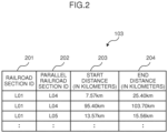
- Fig. 2 is a configuration diagram of railroad section information.
- the railroad section information 103 is information for managing a relation of a railroad section on which each train runs (corresponding railroad section) and a parallel railroad section which is parallel to the railroad section, and is configured from a railroad section ID 201, a parallel railroad section ID 202, a start distance (in kilometers) 203, and an end distance (in kilometers) 204.
- the railroad section ID 201 is an identifier for uniquely identifying the railroad section (corresponding railroad section).
- the railroad section ID 201 stores, for instance, "L01".
- the parallel railroad section ID 202 is an identifier for uniquely identifying the parallel railroad section that is parallel to the railroad section.
- the parallel railroad section ID 202 stores, for instance, "L04" as the identifier of the parallel railroad section that is parallel to the railroad section "L01".
- the start distance (in kilometers) 203 is distance information regarding the start location of the railroad section, and is information indicating the distance from the reference location of the railroad section.
- the start distance (in kilometers) 203 stores, for instance, "7.57 km” as the information indicating the distance from the reference location of the railroad section "L01”.
- the end distance (in kilometers) 204 is distance information regarding the end location of the railroad section, and is information indicating the distance from the reference location of the railroad section.
- the end distance (in kilometers) 204 stores, for instance, "25.40 km” as the information indicating the distance from the reference location of the railroad section "L01 ".
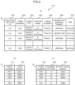
- Fig. 3 is a configuration diagram of peripheral railroad section timetable information.
- the peripheral railroad section timetable information 104 is information for managing a timetable of each train which runs on a peripheral railroad section on a periphery of the corresponding railroad section, and is configured from a plurality of tables 30, 31, 32.
- the table 30 is configured from a railroad section ID 301, a train number 302, a train type 303, a station name 304, a track number 305, a departure/arrival/transit 306, and a time 307
- the table 31 is configured from a train number 311, and a train model 312
- the table 32 is configured from a train number 321, a number of cars 322, and a total train length 323.
- the railroad section ID 301 stores the same information as the railroad section ID 201 of Fig. 2 .
- the train number 302 is a number for identifying the train which runs on the railroad section.
- the train number 302 stores, for instance, "T001" as the number of the train which runs on the railroad section "L01”.
- the train type 303 is information for identifying the type of train which runs on the railroad section.
- the train type 303 stores, for instance, information of "rapid train” in cases where the train which runs on the railroad section "L01" is a "rapid train”.
- the station name 304 is the name of the station located on the railroad section.
- the station name 304 stores information of "A station” when the name of the station located on the railroad section "L01" is "A station”.
- the track number 305 is information indicating the track number of the train which runs through the station located on the railroad section.
- the track number 305 stores, for instance, information of "track number 2" when the train runs through track number 2 of A station located on the railroad section "L01".
- the departure/arrival/transit 306 is information indicating whether the train will leave the station, arrive at the station, or transit through the station.
- the departure/arrival/transit 306 stores, for instance, information of "arrival” when the train will arrive at track number 2 of A station located on the railroad section "L01".
- the time 307 is information indicating the departure time, the arrival time or the transit time of the train.
- the time 307 stores, for instance, information of "16:00:00" when the train will arrive at track number 2 of A station located on the railroad section "L01" at "16:00:00".
- the train number 311 stores the same information as the train number 302.
- the train model 312 is information for identifying the train type of the train.
- the train model 312 stores, for instance, "SS01" as information for identifying the train type of the train of train number "T001 ".
- the train number 321 stores the same information as the train number 302.
- the number of cars 322 is information indicating the total number of cars configuring the train.
- the number of cars 322 stores, for instance, information of "8" when the train of train number "T001" is configured from 8 cars.
- the total train length 323 is information indicating the overall length of the train.
- the total train length 323 stores, for instance, information of "160 m" when the train of train number "T001" is configured from 8 cars and the overall length of the train is "160 m".
- Fig. 3 illustrates the configuration of the peripheral railroad section timetable information 104
- the corresponding railroad section timetable information 101 is also configured from the same information.
- the peripheral railroad section timetable information 104 is configured from three tables 30, 31, 32
- the table configuration is not necessarily limited to this example.
- information of the respective tables may also be summarized in a single table.
- Fig. 4 is a configuration diagram of a running curve.
- the running curve 106 is information for managing the running curve between the stations located on the railroad section, and is configured from a railroad section ID 401, a start station 402, an end station 403, a start station transit/stop 404, an end station transit/stop 405, a distance (in kilometers) 406, a speed 407, an addition-subtraction speed 408, and an elapsed time 409.
- the railroad section ID 401 stores the same information as the railroad section ID 201 of Fig. 2 .
- the start station 402 is the name of the start station located at the start location of the railroad section.
- the start station 402 stores, for instance, information of "A station” when the name of the start station located at the start station of the railroad section "L01" is "A station”.
- the end station 403 is the name of the end station located at the end location of the railroad section.
- the end station 403 stores, for instance, information of "B station” when the name of the end station located at the end location of the railroad section "L01" is "B station”.
- the start station transit/stop 404 is information indicating whether the train will transit through or stop at the start station.
- the start station transit/stop 404 stores, for instance, information of "stop" when the train will stop at the start station.
- the end station transit/stop 405 is information indicating whether the train will transit through or stop at the end station.
- the end station transit/stop 405 stores, for instance, information of "transit” when the train will transit through the end station.
- the distance (in kilometers) 406 is information indicating the distance from the reference location of the railroad section of the start station.
- the speed 407 is information indicating the speed of the train which runs between the start station and the end station.
- the addition-subtraction speed 408 is information indicating the addition-subtraction speed of the train upon running between the start station and the end station.
- the elapsed time 409 is information indicating the time that the train will transit through the start station.
- Fig. 5 is a configuration diagram of railroad track information.
- the railroad track information 108 is information for managing the track circuits configuring the railroad section, and is configured from a railroad section ID 501, a track circuit ID 502, a start distance (in kilometers) 503, and an end distance (in kilometers) 504.
- the railroad section ID 501 stores the same information as the railroad section ID 201 of Fig. 2 .
- the track circuit ID 502 is an identifier for identifying a specific track circuit among a plurality of track circuits configuring the railroad section.
- the track circuit ID 502 stores, for instance, "K001" as the identifier for identifying a specific track circuit among a plurality of track circuits configuring the railroad section "L01".
- the start distance (in kilometers) 503 stores the same information as the start distance (in kilometers) 203 of Fig. 2 .
- the end distance (in kilometers) 504 stores the same information as the end distance (in kilometers) 204 of Fig. 2 .
- Fig. 6 is a configuration diagram of equipment information and equipment update information.
- the equipment information 111 is information for managing equipment disposed on the track circuit of the railroad section (track circuit-related equipment), and is configured from a railroad section ID 601, a track circuit ID 602, a connecting equipment type 603, a connecting equipment ID 604, and an installation distance (in kilometers) 605.
- the equipment update information 135 is configured from a connecting equipment ID 611, an update frequency 612 indicating the update frequency of the corresponding equipment, and an installation/updated date 613 indicating the installation/updated date.
- the railroad section ID 601 stores the same information as the railroad section ID 201 of Fig. 2 .
- the track circuit ID 602 stores the same information as the track circuit ID 502 of Fig. 5 .
- the connecting equipment type 603 is information for identifying the type of equipment to be connected to the track circuit of the railroad section.
- the connecting equipment type 603 stores, for instance, information of "signal" when the equipment to be connected to the track circuit "K001" of the railroad section "L01" is a "signal”.
- the connecting equipment ID 604 is the identifier of the equipment to be connected to the track circuit of the railroad section.
- the connecting equipment ID 604 stores, for instance, "SG001” as the identifier of the "signal” as the equipment to be connected to the track circuit "K001" of the railroad section "L01".
- the installation distance (in kilometers) 605 is information indicating the distance from the reference location of the equipment to be connected to the track circuit of the railroad section.
- the installation distance (in kilometers) 605 stores, for instance, information of "0.00 km” as the distance from the reference location of the "signal” as the equipment to be connected to the track circuit "K001" of the railroad section "L01”.
- the connecting equipment ID 611 stores the same information as the connecting equipment ID 604.
- the update frequency 612 stores the update frequency of the corresponding equipment. Note that 0 is stored for equipment that has not been updated after being installed.
- the installation/updated date 613 stores the date and time that the equipment was installed/updated.
- Fig. 7 is a configuration diagram of operation acquisition information.
- the operation acquisition information 113 is information for managing the relation of the device configuring the equipment to be connected to the track circuit of the railroad section and the acquisition information type, and is configured from a connecting device type 701, and an acquisition information type 702.
- the connecting device type 701 is information for identifying the type of device configuring the equipment to be connected to the track circuit of the railroad section.
- the connecting device type 701 stores, for instance, information of "signal" when the device configuring the equipment to be connected to the track circuit is a "signal".
- the acquisition information type 702 is the type of information to be acquired for managing the device configuring the equipment to be connected to the track circuit.
- the acquisition information type 702 stores, for instance, information of "lighting time, lighting frequency" when the information to be acquired for managing the signal to be connected to the track circuit is "lighting time, lighting frequency”.
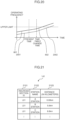
- Fig. 8 is an operating frequency characteristic diagram as an output example of the operation output unit and which shows the operating frequency of the equipment.
- the horizontal axis represents the time
- the vertical axis represents the operating frequency of the equipment (track circuit-related equipment).
- the vertical axis sets, as the upper limit, the operating frequency which refers to the replacement of the equipment pursuant to the degradation of the equipment.
- the present time refers to the timing in which the operating quantity of the respective equipment was aggregated by the track circuit-related equipment operation aggregation unit 112.
- the timetable change time refers to the time that the timetable of each train which runs on the railroad section was changed.
- the characteristic curves 801, 802 are the characteristic curves indicating the changes to the operating frequency of the equipment (operating quantity of the equipment).
- the characteristic curve 801 indicates the changes to the operating frequency of the equipment from before the present time to the timetable change time, with the present time as the borderline.
- the characteristics from the present time to the timetable change time indicate predicted values of the operating frequency of the equipment from the present time onward.
- the characteristics from the timetable change time onward indicate changes to the future operating frequency (change of predicted values) of the equipment.
- the characteristic curves 801, 802 of the operating frequency from the timetable change time onward are the characteristics obtained as the corresponding railroad section timetable information 101 and the peripheral railroad section timetable information 104 based on the timetable information after the timetable change.
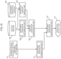
- Fig. 9 is a flowchart explaining the processing of the first embodiment.
- the processor activates the related timetable extraction unit 102.
- the related timetable extraction unit 102 refers to the railroad section information 103 and the peripheral railroad section timetable information 104 based on the input corresponding railroad section timetable information 101, and extracts the related timetable of the peripheral railroad section pertaining to the corresponding railroad section (S11).
- the related timetable extraction unit 102 refers to the railroad section information 103 with the railroad section ID 201 as a search key, and acquires information stored in the parallel railroad section ID 202, the start distance (in kilometers) 203 and the end distance (in kilometers) 204, respectively.
- the related timetable extraction unit 102 refers to the peripheral railroad section timetable information 10 with the parallel railroad section ID 202 as a search key, conducts a search 301 of the railroad section ID, and extracts a corresponding record.
- the extracted peripheral railroad section timetable is configured from information registered in the railroad section ID 301, the train number 302, the train type 303, the station name 304, the track number 305, the departure/arrival/transit 306, and the time 307, respectively. Based on the information of the extracted peripheral railroad section timetable, it is possible to know what train departed from which track number of which station at what time, or know when such train will arrive at which track number, or when such train will transit through which station.
- the total train length 323 it is possible to more realistically simulate the transition of the blocking of the track circuit, and, when the total train length is consequently long, it is possible to simulate that the time required for the crossing gate to be lowered will be long.
- the train dynamic simulation unit 105, the on-rail section simulation unit 107 and the track circuit simulation unit 109 perform processing for each train ID listed in the corresponding timetable (corresponding railroad section timetable information) and the peripheral railroad section timetable (peripheral railroad section timetable information).
- the train dynamic simulation unit 105 refers to the running curve 106, and simulates the service of each train (train dynamic) listed in the corresponding timetable and the peripheral railroad section timetable extracted by the related timetable extraction unit 102 based on the information registered in the running curve 106 (S13).
- the train dynamic simulation unit 105 refers to the running curve 106 with the railroad section ID 401, the start station 402, the end station 403, the start station transit/stop 404, and the end station transit/stop 405 as the search key, searches for information of the running curve between certain stations, and extracts information registered in the distance (in kilometers) 406, the speed 407, the addition-subtraction speed 408, and the elapsed time 409, respectively.
- the train dynamic simulation unit 105 extracts information registered in the running curve 106 between all stations of the railroad section, and, by adding the "elapsed time" registered in the elapsed time 409 among the extracted information to the departure time (or transit time) of each station obtained from the corresponding railroad section timetable information 101, it is possible to comprehend the dynamic (distance (in kilometers), speed, addition-subtraction speed, elapsed time from the departing station (or the transit station)) of the train within the railroad section (train identified with the train ID).
- the timetable of the performance of the corresponding day may be used in substitute for the planned timetable.
- the running curve 106 may be replaced with the past train running information for implementation.
- Fig. 14 is a configuration diagram of the train running information.
- the train running information 120 is stored on the HDD as information for managing the running state of each train which runs on the railroad section, and is configured from a railroad section ID 1401, a train number 1402, a date 1403, a time 1404, a distance (in kilometers) 1405, a speed 1406, an addition-subtraction speed 1407, notch information 1408.
- the railroad section ID 1401 stores the same information as the railroad section ID 201 of Fig. 2 .
- the train number 1402 stores the same information as the train number 302 of Fig. 3 .
- the date 1403 is information indicating the date that the train ran on the railroad section.
- the time 1404 is information indicating the time that the train ran on the railroad section.
- the distance (in kilometers) 1405 stores the same information as the distance (in kilometers) 406 of Fig. 4 .
- the speed 1406 stores the same information as the speed 407 of Fig. 4 .
- the addition-subtraction speed 1407 stores the same information as the addition-subtraction speed 408 of Fig. 4 .
- the notch information 1408 stores "2" as the notch information of the train which runs on the railroad section.
- Fig. 21 is a configuration diagram of the station distance (in kilometers) information.
- the station distance (in kilometers) information 141 is stored on the HDD as information for managing the station distance (in kilometers), and is configured from a railroad section ID 2101, a station name 2102, and a distance (in kilometers) 2103.
- the railroad section ID 2101 stores the same information as the railroad section ID of Fig. 3 .
- the station name 2102 stores the same information as the station name 304 of Fig. 3 .
- the distance (in kilometers) 2103 stores the length of the route from the starting station of each railroad section.
- the train dynamic simulation unit 105 acquires the railroad section ID 2101 of the corresponding railroad section of the distance (in kilometers) information 141, and the distance (in kilometers) information 2103 of the departing station and the destination station, respectively based on the station name 2102 of the departing station and the station name (2102) of the destination station between the corresponding stations. Subsequently, based on the distance (in kilometers) information 2103, the train dynamic simulation unit 105 refers to the corresponding railroad section ID 1401 and the distance (in kilometers) information 1405 from the train running information 120, and acquires records between the departing station distance (in kilometers) and the destination station distance (in kilometers).
- the acquired records will be information configured from the items of the date 1403, the time 1404, the train number 1402, the distance (in kilometers) 1405, the speed 1406, and the addition-subtraction speed 1407 between the departing station distance (in kilometers) and the destination station distance (in kilometers).
- These records show the series of dynamics from the departing station to the destination station for each train number 1402.
- the running curve 106 can be replaced with the past train running information for implementation.
- the running curve 106 may be entirely replaced with train running information for implementation, or the train running information and the running curve may be combined for implementation.
- the running curve may be used to supplement such deficiency.
- the on-rail section simulation unit 107 and the track circuit simulation unit 109 perform processing based on the elapsed time from the departing station (or from the transit station) obtained with the train dynamic simulation unit 105.
- the on-rail section simulation unit 107 acquires the on-rail section information at each point in time based on the dynamic obtained with the train dynamic simulation unit 105 (S14). Specifically, the on-rail section simulation unit 107 refers to the railroad track information 108 with the railroad section ID 501, the start distance (in kilometers) 503, and the end distance (in kilometers) 504 as the search key, and acquires information registered in the track circuit ID 502. The acquired information configures the on-rail section information indicating which train (train identified with the train ID) exists on which track circuit (track circuit identified with the track circuit ID). Moreover, the on-rail section simulation unit 107 can simulate when the track circuit, which was once on-rail, will no longer be on-rail by referring to the information registered in the total train length of the corresponding railroad section timetable information 101.
- the track circuit simulation unit 109 simulates the operation of the track circuit based on the on-rail section information generated by the on-rail section simulation unit 107, and the railroad track information 108 (S15). Specifically, the track circuit simulation unit 109 determines the state of adjacent track circuits based on the train interval control system according to the on-rail section information. For example, when the train interval control system is a system where the two rearward track circuits are blocked, blocking is set to the on-rail section and the two rearward track circuits of the on-rail section.
- the track circuit simulation unit 109 can simulate the state of the track circuits according to the on-rail condition of each train listed in the timetable of the corresponding railroad section and the peripheral railroad section.
- the track circuit-related equipment operation simulation unit 110 refers to a simulation result of the track circuit simulation unit 109, and the equipment information 111, and simulates an operation of the track circuit-related equipment based on the state of each track circuit, and the equipment information 111 (S16). Specifically, the track circuit-related equipment operation simulation unit 110 refers to the equipment information 111 with the railroad section ID 601 and the track circuit ID 602 as the search key, and acquires information registered in the connecting equipment type 603, the connecting equipment ID 604, and the installation distance (in kilometers) 605, respectively. It is possible to comprehend the track circuit-related equipment in each track circuit from the acquired information (simulation result).
- the track circuit-related equipment operation simulation unit 110 can determine the operation of each track circuit-related equipment based on the blocked state. For example, a signal will flash in red when the on-rail section is blocked. Note that these track circuit-related equipment are controlled based on a train interval control system designated in each railroad section.
- the track circuit-related equipment operation aggregation unit 112 refers to the operation acquisition information 113 of each equipment, and aggregates the state (operating quantity) of the track circuit-related equipment (S19).
- the track circuit-related equipment operation aggregation unit 112 refers to the operation acquisition information 113 with the connecting device type 701 as the search key, and acquires information registered in the acquisition information type 702.
- the state (operating quantity) of the connecting equipment is aggregated by using the information registered in the acquisition information type 702; for instance, in the case of a signal, information such as "lighting time" and "lighting frequency".
- the track circuit-related equipment operation aggregation unit 112 consequently aggregates the operating quantity of the equipment simulated by the track circuit-related equipment operation simulation unit 110.
- the lighting time of a signal lighting state ⁇ interval time are aggregated, and the aggregated time is estimated, and managed, as the total lighting time of the signal (operating quantity of the signal).
- the crossing gate operation frequency the time change of the operation of the equipment is referenced, and the series of operations where the crossing gate is raised and subsequently lowered is counted as one operation and aggregated, and the aggregated frequency is estimated, and managed, as the total frequency of the crossing gate operation (operating quantity of the crossing gate).
- the operation output unit 114 outputs information aggregated by the track circuit-related equipment operation simulation unit 110 (for instance, total lighting time of the signal (operating quantity of the signal) and total frequency of the crossing gate operation (operating quantity of the crossing gate) to a display device, and displays the aggregated information the display device (S20), and then ends the processing of this routine.
- information aggregated by the track circuit-related equipment operation simulation unit 110 for instance, total lighting time of the signal (operating quantity of the signal) and total frequency of the crossing gate operation (operating quantity of the crossing gate) to a display device, and displays the aggregated information the display device (S20), and then ends the processing of this routine.
- the screen of the display device displays, as shown in Fig. 8 , information aggregated by the track circuit-related equipment operation simulation unit 110; for instance, the operating frequency (total frequency) of the crossing gate obtained by aggregating the operating frequency for each set-up timing, as the characteristics indicating the operating quantity of the crossing gate.
- the display example of Fig. 8 indicates the changes to the operating frequency of the equipment from before the present time to the timetable change time, with the present time as the borderline.
- the characteristics from the present time to the timetable change time indicate predicted values of the operating frequency of the equipment from the present time onward.
- the information aggregated by the track circuit-related equipment operation simulation unit 110 is the total lighting time of the signal (operating quantity of the signal) obtained by aggregating the operating time for each set-up timing, the characteristics indicating the total lighting time of the signal (operating quantity of the signal) are displayed on the screen of the display device.
- the characteristics from the timetable change time onward indicate changes to the future operating frequency (change of predicted values) of the equipment.
- the value of the performance may be obtained as the operating frequency up to the present time
- the value estimated with the method explained in this embodiment may also be used.
- the value of the operating frequency predicted with the method of this embodiment is used. Note that, while the operating frequency of the equipment is displayed in the timetable change time, this indicates that the number of timetable services has changed from the timetable change time, and the impact thereof is impacting the changes to the operating frequency of the equipment. Accordingly, when the method of this embodiment is used, it is possible to estimate the change in impact after the condition is changed, and accurately indicate when an abnormality will occur.
- the range of simulating the operation of the equipment by changing the time is from the train dynamic simulation processing (S13) to the track circuit-related equipment operation simulation processing (S16), and, after performing the various simulations from the start time to the end time, the results are aggregated in the track circuit-related equipment operation aggregation processing (S19).
- the track circuit-related equipment operation aggregation unit 112 can predict (estimate) the degradation of the crossing gate based on the prediction result (estimation result) according to Formula (1) below.
- Degradation level Yt a ⁇ Xt + b
- the track circuit-related equipment operation aggregation unit 112 can cause the operation output unit 114 to output display information to the effect of urging the repair of the crossing gate.
- the track circuit-related equipment operation aggregation unit 112 can predict (estimate) the degradation of the crossing gate based on the prediction result (estimation result) according to Formula (2) below.
- Degradation level Yt a ⁇ Xt + b
- Xt as the cumulative operating time can be obtained based on whether or not the crossing gate is being operated for each corresponding time of predictive simulation in cases of executing predictive simulation at fixed intervals.
- the processing unit (related timetable extraction unit 102, train dynamic simulation unit 105, on-rail section simulation unit 107, track circuit simulation unit 112 and track circuit-related equipment operation simulation unit 110) simulates, as the operation mode of the equipment, at least one of either the operating frequency or the operating time of the equipment based on the corresponding railroad section timetable information 101, and can simulate, as the operation mode of the equipment, at least one of either the past operating frequency or the past operating time of the equipment by using the past corresponding railroad section timetable information indicating the past timetable of each train as the corresponding railroad section timetable information 101.
- the estimation unit can aggregate the operating quantity of each track circuit-related equipment from the simulation result of the processing unit, and estimate the degradation of each track circuit-related equipment from the aggregation result.
- the processing unit inputs the peripheral railroad section timetable information 104 which manages a timetable of each train which runs on a peripheral railroad section disposed on a periphery of the corresponding railroad section, and simulates, as an operation mode of the equipment, at least one of either an operating frequency or an operating time of equipment among each of the equipment that is impacted by the peripheral railroad section timetable information 104 based on each piece of timetable information that was input and the equipment information 111 which manages a relation of equipment, which is disposed on each of the railroad sections, and each of the railroad sections, in addition to the corresponding railroad section timetable information 101.
- the processing unit can simulate a travel transition of each train existing in the corresponding railroad section timetable information 101 as a dynamic of each of the trains based on the corresponding railroad section timetable information 101 and the running curve 106 between the stations existing in the corresponding railroad section, simulate a state change of each of the track circuits based on the simulation result and the railroad track information 108 which manages a length of a plurality of track circuits existing in the corresponding railroad section, and simulate an operational change of equipment disposed on each of the track circuits based on the simulation result and the equipment information 111 which manages a relation of equipment, which is disposed on each of the track circuits, and each of the track circuits.
- the estimation unit can aggregate the simulation results indicating the operational change of the equipment disposed on each of the track circuits, and estimate the degradation of the equipment disposed on each of the track circuits from the aggregation result.
- this embodiment it is possible to simulate the operation of the track circuit-related equipment based on the corresponding railroad section timetable information 101, aggregate the operating quantity of each track circuit-related equipment from the simulation result, and estimate the degradation of each track circuit-related equipment from the aggregation result.
- it is possible to estimate the degradation of numerous types of ground equipment in comparison to conventional methods, as well as predict and aggregate the future operation of the ground equipment it is possible to make a forecast on when an abnormality will occur in the respective ground equipment.
- equipment related to an interlocking device equipment to be controlled by the interlocking device
- equipment related to an interlocking device refers to equipment in which is operated based on the operation of the interlocking device, and, for instance, considered may be home signals and points.
- Fig. 10 is a configuration diagram showing the second embodiment of the degradation estimation system of railroad ground equipment according to the present invention.
- the degradation estimation device of railroad ground equipment in this embodiment is configured by deleting the related timetable extraction unit 102, the railroad section information 103 and the peripheral railroad section timetable information 104 shown in Fig. 1 , adding an interlocking device simulation unit 115, a wiring schematic 116 and an interlocking table 117, and arranging an interlocking device-related equipment operation simulation unit 118 and an interlocking device-related equipment operation aggregation unit 119 in substitute for the track circuit-related equipment operation simulation unit 110 and the track circuit-related equipment operation aggregation unit 112, and the remaining configuration is the same as the first embodiment shown in Fig.
- the wiring schematic 116 and the interlocking table 117 are stored in the HDD.
- the interlocking device simulation unit 115 and the interlocking device-related equipment operation simulation unit 118 are configured as one element of the processing unit
- the interlocking device-related equipment operation aggregation unit 119 is configured as one element of the estimation unit, respectively stored in the memory, and activated by the processor.
- the interlocking device simulation unit 115 simulates an output of the interlocking device based on the wiring schematic 116 and the interlocking table 117, and based on the state of each track circuit determined by the track circuit simulation unit 109.
- the interlocking device-related equipment operation simulation unit 118 refers to the equipment information 111 based on the state of the track circuit and the track number information obtained from the timetable information, and determines the state of railroad ground equipment such as signals and points.
- the interlocking device-related equipment operation aggregation unit 119 aggregates the operation history of the respective equipment based on the interlocking device-related equipment information simulated by the interlocking device-related equipment operation simulation unit 118, and the operation acquisition information 113.
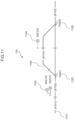
- Fig. 11 is a configuration diagram of a wiring schematic.
- the wiring schematic 116 is a diagram for managing the connection relation of the equipment to be controlled by the interlocking device, and the track circuit, and a railroad track 1102 is connected to a railroad track 1101 around the station.
- the railroad track 1101 configuring the main line is configured from track circuits K101, K102, K103
- the railroad track 1102 configuring the branch line is configured from a track circuit K104 which is branched from the track circuit K102 and connected to the track circuit K103.
- a main line SIG101 and a branch line SIG102 as a home signal 1103 are connected to the track circuit K102, and a leaving signal 1104 is connected to the track circuit K104.
- a point 1105 is disposed between the track circuit K102 and the track circuit K104, and a point 1106 is connected between the track circuit K104 and the track circuit K103.
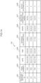
- Fig. 12 is a configuration diagram of an interlocking table in a track circuit.
- the interlocking table 117 is a table for managing a relation of equipment to be controlled by the interlocking device and the control contents of the interlocking device upon controlling the equipment, and is configured from equipment type 1201, a connecting equipment ID 1202, a lock 1203, and a signal control 1204.
- the equipment type 1201 is information indicating the type of equipment to be controlled by the interlocking device.
- the equipment type 1201 stores, for instance, information of "signal (main line)" when the equipment to be controlled by the interlocking device is a "main line signal".
- the connecting equipment ID 1202 is an identifier for uniquely identifying the equipment to be controlled by the interlocking device.
- the connecting equipment ID 1202 stores, for instance, information of "SG101" when the identifier of the "main line signal" is "SG101".
- the lock 1203 is information for identifying the equipment to be locked by the interlocking device.
- the lock 1203 stores, for instance, "TN001” as the information for identifying "point” when the equipment to be locked by the interlocking device is a "point”. Note that "(TN001)" is stored when the "point” is inverted.
- the signal control 1204 is information for identifying the target of the signal control of the interlocking device.
- the signal control 1204 stores, for instance, "K102, K103" as information for identifying the "track circuit” when the target of the signal control of the interlocking device is a "track circuit".
- the interlocking device simulation unit 115 determines the state of railroad ground equipment such as signals and points based on the state of the track circuit, and the track number information obtained from the timetable information. For example, when the track is on-rail of the track circuit K101 of Fig. 11 and will advance to the branch line of the track circuit K104, the interlocking device simulation unit 115 selects "(TN001)" as the lock 1203 with reference to the information of the signal (branch line) of the interlocking table 117 of Fig. 12 , and determines the state of the related track circuit. Once the state of the track circuit and the state of the ground equipment are determined, processing by the interlocking device-related equipment operation aggregation unit 119 is performed.
- this embodiment does not limit the method, and a method according to the circumstances of the respective railroad sections is selected and executed. It is thereby possible to simulate the interlocking device, and simulate the operation of the respective interlocking device-related equipment operation aggregation units.
- the interlocking device-related equipment operation aggregation unit 119 aggregates the operation history of the respective equipment (operating quantity of the equipment) based on the interlocking device-related equipment information simulated by the interlocking device-related equipment operation simulation unit 118, and the operation acquisition information 113.
- the same processing as the track circuit-related equipment operation aggregation unit 112 of Fig. 1 can be adopted.
- support information for estimating the degradation of equipment is generated regarding the equipment that is impacted by the dynamic of the train.
- the equipment that is impacted by the dynamic of the train considered may be, for example, rails and trolley lines.
- the degradation of these equipment is considered to be impacted by the transit frequency, the transit speed, and the addition-subtraction speed during the transit of the train.
- Fig. 13 is a configuration diagram showing the third embodiment of the degradation estimation system of railroad ground equipment according to the present invention.
- the degradation estimation device of railroad ground equipment in this embodiment is configured by comprising a train dynamic simulation unit 105, equipment impact simulation unit 121, equipment impact aggregation unit 123, and an operation output unit 114.
- the equipment impact simulation unit 121 is configured as one element of the processing unit
- the equipment impact aggregation unit 123 is configured as one element of the estimation unit, respectively stored in the memory, and activated by the processor.
- the train dynamic simulation unit 105 simulates (comprehends) the train running at each location based on the train running information 120 indicating the service performance of each train in addition to the corresponding railroad section timetable information 101 and the running curve 106.
- the train dynamic simulation unit 105 simulates, as the train dynamic, the train running at each location regarding all trains included in the corresponding railroad section timetable information 101.
- the equipment impact simulation unit 121 calculates the impact of the equipment based on the train dynamic obtained with the train dynamic simulation unit 105, and the equipment impact information 122.
- the equipment impact simulation unit 121 calculates the impact of the equipment regarding all trains included in the corresponding railroad section timetable information 101.
- the equipment impact aggregation unit 123 aggregates the impact evaluation of the equipment based on the calculation result (simulation result) of the equipment impact simulation unit 121. This aggregation result can be used as the support information for estimating the degradation of the equipment that is impacted by the dynamic of the train.
- the operation output unit 114 outs the information aggregated by the equipment impact aggregation unit 123 to, for example, the display device.
- Fig. 14 is a configuration diagram of train running information.
- the train running information 120 is stored on the HDD as the information for managing the running state of each train which runs on the railroad section, and is configured from a railroad section ID 1401, a train number 1402, a date 1403, a time 1404, a distance (in kilometers) 1405, a speed 1406, an addition-subtraction speed 1407, and notch information 1408.
- the railroad section ID 1401 stores the same information as the railroad section ID 201 of Fig. 2 .
- the train number 1402 stores the same information as the train number 302 of Fig. 3 .
- the date 1403 is information indicating the date that the train ran on the railroad section.
- the time 1404 is information indicating the time that the train ran on the railroad section.
- the distance (in kilometers) 1405 stores the same information as the distance (in kilometers) 406 of Fig. 4 .
- the speed 1406 stores the same information as the speed 407 of Fig. 4 .
- the addition-subtraction speed 1407 stores the same information as the addition-subtraction speed 408 of Fig. 4 .
- the notch information 1408 stores "2" as the notch information of the train which runs on the railroad section.
- Fig. 15 is a configuration diagram of equipment impact information.
- the equipment impact information 122 is stored on the HDD as information for managing a relation of the equipment disposed on the railroad section and the impact evaluation, and is configured from an device type 1501, and an impact evaluation 1502.
- the device type 1501 is information indicating the type of equipment configuration the equipment that will be impacted by the dynamic of the train.
- the device type 1501 stores, for instance, information of "rails" when the equipment that will be impacted by the dynamic of the train is "rails".
- the impact evaluation 1502 is an item for evaluating the impact of the equipment that will be impacted by the dynamic of the train.
- the impact evaluation 1502 stores, for instance, information of "addition-subtraction speed" when the "rails” will be impacted by the "addition-subtraction speed” of the train among the dynamics of the train.
- the train dynamic simulation unit 105 simulates, as the train dynamic, the train running at each location based on the train running information 120 indicating the service performance of each train in addition to the corresponding railroad section timetable information 101 and the running curve 106.
- the train dynamic simulation unit 105 refers to the train running information 120 with the railroad section ID 1401 and the train number 1402 as the search key, and acquires information stored in the date 1403, the time 1404, the distance (in kilometers) 1405, the speed 1406, the addition-subtraction speed 1407, and the notch information 1408, respectively.
- the equipment impact simulation unit 121 calculates the impact of the equipment by using the train dynamic obtained with the train dynamic simulation unit 105, and the equipment impact information 122.
- the equipment impact simulation unit 121 refers to the equipment impact information 122 with the device type 1501 as the search key, extracts the information of the impact evaluation 1502 corresponding to the type stored in the device type 1501, and performs the impact evaluation of the equipment based on the extracted information. For example, when the equipment impact simulation unit 121 selects "rails" as the device type 1501 and selects "addition-subtraction speed" as the impact evaluation 1502, the equipment impact simulation unit 121 executes the impact evaluation of the impacted "rails" based on the information registered in the addition-subtraction speed 1407 of the train running information 120.
- the equipment impact aggregation unit 123 aggregates the impact evaluation output by the equipment impact simulation unit 121.
- the equipment impact aggregation unit 123 can generate support information for estimating the degradation of the equipment that is impacted by the dynamic of the train by aggregating the impact evaluation output by the equipment impact simulation unit 121.
- the same processing as the track circuit-related equipment operation aggregation unit 112 of Fig. 1 can be adopted.
- the equipment impact aggregation unit 123 can predict the degradation of the rails according to Formula (3) below.
- Degradation level Yt a ⁇ X1t + b ⁇ X2t + c ⁇ X1t ⁇ X2t + d
- the operation mode of the equipment is estimated from the past history without simulating the track circuit or the interlocking device, and the operating quantify related to the future degradation of the equipment is estimated.
- Fig. 16 is a configuration diagram showing the fourth embodiment of the degradation estimation system of railroad ground equipment according to the present invention.
- the degradation estimation device of railroad ground equipment in this embodiment is configured from a train dynamic simulation unit 105, an on-rail section simulation unit 107, equipment operation history search unit 124, equipment operation aggregation unit 127, and an operation output unit 114.
- the equipment operation history search unit 124 is configured as one element of the processing unit
- the equipment operation aggregation unit 127 is configured as one element of the estimation unit, respectively stored in the memory, and activated by the processor.
- the train dynamic simulation unit 105 refers to the running curve 106, and simulates the dynamic of the train.
- the train dynamic simulation unit 105 simulates, as the train dynamic, the training running at each location regarding all trains included in the timetable information of the corresponding railroad section.
- the on-rail section simulation unit 107 refers to the railroad track information 108 based on the simulation result of the train dynamic simulation unit 105, and generates on-rail section information of each train.
- the on-rail section simulation unit 107 generates on-rail section information indicating on which track circuit each train exists regarding all trains included in the corresponding railroad section timetable information 101.
- the equipment operation history search unit 124 refers to the service history 125 and the equipment operation history 126, and searches for the most similar case example from the past history based on the on-rail section information of each train.
- the equipment operation aggregation unit 127 aggregates the search result of the equipment operation history search unit 124 as the operation (operating quantity) of the equipment, and outputs the aggregation result to the operation output unit 114.
- the operation output unit 114 outputs the information aggregated by the equipment operation aggregation unit 127 to, for example, the display device.
- Fig. 17 is a configuration diagram of service history information.
- the service history 125 is stored on the HDD as information for managing the service history of each train which runs on the railroad section, and is configured from a railroad section ID 1701, a train number 1702, a station name 1703, a track number 1704, a departure/arrival/transit 1705, an implementation date 1706, an implementation time 1707, an on-rail section 1708, a distance (in kilometers) 1709, and a speed 1710.
- the railroad section ID 1701 stores the same information as the railroad section ID of Fig. 3 .
- the train number 1702 stores the same information as the train number 302 of Fig. 3 .
- the station name 1703 stores the same information as the station name 304 of Fig. 3 .
- the track number 1704 stores the same information as the track number 305 of Fig. 3 .
- the departure/arrival/transit 1705 stores the same information as the departure/arrival/transit 306 of Fig. 3 .
- the implementation date 1706 stores information of the date that the service history of each train was stored.
- the implementation time 1707 stores information indicating the time (hour:minute:second) that the service history of each train was stored.
- the on-rail section 1708 stores information of the track circuit on which each train is on-rail.
- the distance (in kilometers) 1709 stores the same information as the distance (in kilometers) 406 of Fig. 4 .
- the speed 1710 stores the same information as the speed 407 of Fig. 4
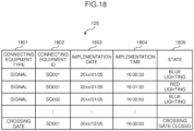
- Fig. 18 is a configuration diagram of equipment operation history information.
- the equipment operation history 126 is stored on the HDD as information for managing the operation history of each equipment disposed on the railroad section, and is configured from a connecting equipment type 1801, a connecting equipment ID 1802, an implementation date 1803, an implementation time 1804, and a state 1805.
- the connecting equipment type 1801 stores the same information as the connecting equipment type 603 of Fig. 6 .
- the connecting equipment ID 1802 stores the same information as the connecting equipment ID 604 of Fig. 6 .
- the implementation date 1803 stores the same information as the implementation date 1706 of Fig. 17 .
- the implementation time 1804 stores the same information as the implementation time 1707 of Fig. 17 .
- the state 1805 stores information indicating the operation state of the equipment registered in the connecting equipment type 1801. For example, when the operation state of the "signal" is "blue lighting", information of "blue lighting" is stored.
- the record when a plurality of operations is to be performed in a single state so that a plurality of signals are lit in a single state in a multi-lighting type signal, the record may be separately stored. For example, with a four-bulb type signal, two yellow signals are lit in a "warning" state.
- two records may be stored, and the state information of the first record may be "first yellow lighting", and the state information of the second record may be "second yellow lighting”. Consequently, it will be possible to easily aggregate the operation of each bulb.
- the train dynamic simulation unit 105 refers to the running curve 106, and simulates, as the train dynamic, the train running at each location regarding all trains included in the corresponding railroad section timetable information 101.
- the on-rail section simulation unit 107 refers to the railroad track information 108 based on the simulation result of the train dynamic simulation unit 105, and generates on-rail section information of each train.
- the equipment operation history search unit 124 searches for the most similar case example from the past history in two stages based on the on-rail section information of each train. In other words, the equipment operation history search unit 124 searches for the service history, which is closest to the first service history, from the service history 125, and subsequently refers to the equipment operation history 126 from the searched service history to search for the equipment operation history.
- the equipment operation history search unit 124 refers to the service history 125 with the railroad section ID 1701 and the on-rail section 1708 as the search key, and searches for the information registered in the implementation date 1706 and the implementation time 1707, respectively.
- the equipment operation history search unit 124 refers to the service history 125 with the railroad section ID 1701 and the on-rail section 1708 as the search key, and searches for the information registered in the implementation date 1706 and the implementation time 1707, respectively.
- information which satisfies the on-rail section information of each train and which has the same implementation date and the implementation time is searched. For example, when there is a train configured from four cars at the time of a certain evaluation, the result obtained with the on-rail section information of each train as the search key will be of the same search date and search time.
- the equipment operation history search unit 124 searches the operation history of the equipment by using the implementation date 1706 and the implementation time 1707.
- the equipment operation history search unit 124 refers to the equipment operation history 126 with the implementation date 1803 and the implementation time 1804 as the search key, and acquires information registered in the connecting equipment type 1801, the connecting equipment ID 1802, and the state 1805, respectively.
- the equipment operation aggregation unit 127 aggregates the information acquired by the equipment operation history search unit 124 as the operation (operating quantity) of the equipment, and outputs the aggregation result to the operation output unit 114. Note that, when the equipment operation history search unit 124 searches for a plurality of case examples, the equipment operation history search unit 124 may select one of those case examples, or statistically obtain the average value based on the distribution of the case examples.
- the service history 125 may be searched based on the dynamic (for instance, the location) of the train obtained from the train dynamic simulation unit 105. Moreover, when searching for the equipment operation history 126, information stored in the implementation date 1803 and the implementation time 1804 may be obtained with the distance (in kilometers) 1709 as the search key.
- the same equipment may be selected in consideration of the arrival/transit of the next station of the train. For example, when the target train stops at B station, the train that stops at B station may be selected from the service history 125.
- This fifth embodiment does not form part of the invention defined in the appended claims but is presented here for illustrative purposes.
- the operation of the equipment is predicted upon predicting the future degradation in light of conditions that are being operated, other than train control, due to service reasons.
- Fig. 19 is a configuration diagram showing the fifth embodiment of the degradation estimation system of railroad ground equipment according to the present invention.
- the degradation estimation device of railroad ground equipment in this embodiment is configured from equipment operation estimation unit 128, an operation history search unit 129, a service operation aggregation unit 130, equipment operation prediction unit 131, equipment operation aggregation unit 127, and an operation output unit 114.
- the equipment operation estimation unit 128, the operation history search unit 129, the service operation aggregation unit 130 and the equipment operation prediction unit 131 are stored in the memory, and activated by the processor.
- the equipment operation estimation unit 128 refers to the service history 125, and estimates the operation of the equipment, which is incidental to the track circuit or the interlocking device, based on the past service history. Specifically, this can be realized by executing the processing from the related timetable extraction unit 102 to the track circuit-related equipment operation aggregation unit 112 in the first embodiment, or by executing the processing from the train dynamic simulation unit 105 to the interlocking device-related equipment operation aggregation unit 119 in the second embodiment.
- the operation history search unit 129 searches for the result of the equipment operation which combines the operation of the equipment based on train control (equipment to be subject to train control) and the operation of the equipment not subject to train control (equipment excluded from train control).
- the operation history search unit 129 refers to the service history 125 and searches the service history of each train, refers to the equipment operation history 126 based on the service history of each train that was searched and searches the equipment operation history in relation to the service history of each train, and aggregates the search results.
- the service operation aggregation unit 130 calculates the amount of operation of the equipment excluding train control by subtracting the estimation result of the equipment operation estimation unit 128 from the aggregation result of the operation history search unit 129. It is possible to estimate the operating quantity of the equipment excluding train control (for instance, operating quantity in the case of operating the equipment for antifreeze) from the calculation result.
- the equipment operation prediction unit 131 predicts the operation of the equipment from the present time toward the future based on the corresponding railroad section timetable information 101.
- the processing contents of the equipment operation prediction unit 131 are basically the same as the processing contents of the equipment operation estimation unit 128, but while the equipment operation estimation unit 128 estimates the past performance from the service history registered in the service history 125, the equipment operation prediction unit 131 estimates the operation of the ground equipment related to train control based on future services by using the corresponding railroad section timetable information 101.
- the equipment operation aggregation unit 127 aggregates the future operating quantity of the equipment based on the operation estimate (prediction result) related to train control obtained with the equipment operation prediction unit 131 and the operation estimate excluding train control obtained with the service operation aggregation unit 130, and outputs the aggregation result to the operation output unit 114.
- the operation output unit 114 outputs the information aggregated with the equipment operation aggregation output unit 1806 to, for example, the display device.
- the operating quantity excluding train control is also output from the operation output unit 114, it is possible to estimate the degradation more accurately.
- the same processing as the track circuit-related equipment operation aggregation unit 112 of Fig. 1 can be adopted.
- Fig. 20 is a characteristic diagram showing a display example of the display device in the fifth embodiment.
- the screen of the display device displays, in addition to the characteristic curves 801, 802, a characteristic curve 2001 indicating the aggregation result of the operation (operating quantity) of the equipment based on train control, and a characteristic curve 2002 indicating the aggregation result of the operation (operating quantity) of the equipment based on train control + the aggregation result of the operation (operating quantity) of the equipment excluding train control. Since the characteristic curve 2001 and the characteristic curve 2002 are displayed, it is possible to comprehend the cause of the degradation of the equipment.
- the operation mode of the equipment based on the corresponding railroad section timetable information 101, estimate the operation (operating quantity) of the equipment based on train control and the operation (operating quantity) of the equipment excluding train control based on the service history 125 and the equipment operation history 126, aggregate the prediction result and the estimation result, and predict the operation of the equipment upon predicting the future degradation from the aggregation result.
- the processing unit can calculate the transit time (time from the transit start time to the transit end time) that each train transits through the equipment disposed on the corresponding railroad section based on the train running information for managing a relation of the total train length of each train which runs on the corresponding railroad section and the speed of each train (information obtained by adding the total train length to the train running information 120) and the corresponding railroad section timetable information 101, and simulate, as the operation mode of the equipment, of at least either the operating frequency or the operating time of the equipment based on the calculation result.
- each of the foregoing configurations and functions may also be realized with software by the processor interpreting and executing programs that realize the respective functions.
- Information such as programs, tables and files for realizing the respective functions may be stored in a memory or a storage device such as a hard disk or an SSD (Solid State Drive), or stored in a recording medium such as an IC (Integrated Circuit) card, an SD (Secure Digital) memory card, or a DVD (Digital Versatile Disc).
Landscapes
- Engineering & Computer Science (AREA)
- Mechanical Engineering (AREA)
- Automation & Control Theory (AREA)
- Physics & Mathematics (AREA)
- General Physics & Mathematics (AREA)
- Theoretical Computer Science (AREA)
- Health & Medical Sciences (AREA)
- Biomedical Technology (AREA)
- General Health & Medical Sciences (AREA)
- General Engineering & Computer Science (AREA)
- Geometry (AREA)
- Evolutionary Computation (AREA)
- Computer Hardware Design (AREA)
- Train Traffic Observation, Control, And Security (AREA)
- Testing And Monitoring For Control Systems (AREA)
Claims (9)
- System zum Schätzen einer Funktionsminderung einer Bahnkörper-Bodenausrüstung, um eine Funktionsminderung einer Bahnkörper-Bodenausrüstung zu schätzen, wobei das System Folgendes umfasst:eine Verarbeitungseinheit (102, 105, 107, 109, 110), die konfiguriert ist, auf der Basis von Fahrplaninformationen (101) des entsprechenden Bahnkörperabschnitts bei einem Fahrplan mehrerer Züge, die auf einem entsprechenden Bahnkörperabschnitt fahren, der simuliert werden soll, eine Betriebsart einer Ausrüstung zu simulieren, die am entsprechenden Bahnkörperabschnitt angeordnet ist; undeine Schätzeinheit (112, 114), die konfiguriert ist, jedes Verarbeitungsergebnis der Verarbeitungseinheit (102, 105, 107, 109, 110) zu sammeln, und konfiguriert ist, eine Funktionsminderung der Ausrüstung aus dem Sammelergebnis zu schätzen,dadurch gekennzeichnet, dass die Verarbeitungseinheit (102, 105, 107, 109, 110) konfiguriert ist, Fahrplaninformationen (104) von umliegenden Bahnkörperabschnitten (104) eines Fahrplans jedes Zugs, der auf einem umliegenden Bahnkörperabschnitt fährt, der in der Umgebung des entsprechenden Bahnkörperabschnitt angeordnet ist, einzugeben, und konfiguriert ist, als die Betriebsart der Ausrüstung eine Betriebshäufigkeit und/oder eine Betriebszeit einer Ausrüstung von allen Ausrüstungen, die am entsprechenden Bahnkörperabschnitt angeordnet sind, die eine Ausrüstung umfassen, die von den Fahrplaninformationen (104) des umliegenden Bahnkörperabschnitts betroffen ist, zusätzlich zu den Fahrplaninformationen (101) des entsprechenden Bahnkörperabschnitts auf der Basis der folgenden Informationen zu simulieren:jedes Element von Fahrplaninformationen eines umliegenden Bahnkörperabschnitts, das eingegeben wurde; undAusrüstungsinformationen (111), die eine Beziehung zwischen einer Ausrüstung (604), die an jedem der Bahnkörperabschnitte angeordnet ist, und jedem der jeweiligen Bahnkörperabschnitte (601) bereitstellen.
- System zum Schätzen einer Funktionsminderung einer Bahnkörper-Bodenausrüstung nach Anspruch 1,
wobei die Verarbeitungseinheit (102, 105, 107, 109, 110) konfiguriert ist, als die Betriebsart der Ausrüstung eine zurückliegende Betriebshäufigkeit und/oder eine zurückliegende Betriebszeit der Ausrüstung zu simulieren, indem entsprechende zurückliegende Fahrplaninformationen des Bahnkörperabschnitts verwendet werden, die einen zurückliegenden Fahrplan jedes der Züge als die Fahrplaninformationen (101) des entsprechenden Bahnkörperabschnitts angeben. - System zum Schätzen einer Funktionsminderung einer Bahnkörper-Bodenausrüstung nach Anspruch 1,
wobei die Verarbeitungseinheit (102, 105, 107, 109, 110) konfiguriert ist, eine Durchgangszeit, in der jeder der Züge die Ausrüstung passiert, die am entsprechenden Bahnkörperabschnitt angeordnet ist, auf der Basis von Trainings-Fahrinformationen zu berechnen, die eine Beziehung zwischen einer Gesamtzuglänge (323) des jeweiligen Zugs, der auf dem entsprechenden Bahnkörperabschnitt fährt, und einer Geschwindigkeit des jeweiligen Zugs und den Fahrplaninformationen (101) des entsprechenden Bahnkörperabschnitts bereitstellen, und konfiguriert ist, als die Betriebsart der Ausrüstung die Betriebshäufigkeit und/oder die Betriebszeit der Ausrüstung auf der Basis des Berechnungsergebnisses zu simulieren. - System zum Schätzen einer Funktionsminderung einer Bahnkörper-Bodenausrüstung nach Anspruch 1,wobei die Verarbeitungseinheit (102, 105, 107, 109, 110) konfiguriert ist, einen Bewegungsübergangjedes Zugs, der in den Fahrplaninformationen (101) des entsprechenden Bahnkörperabschnitts vorhanden ist, als eine Dynamik jedes der Züge auf der Basis der Fahrplaninformationen (101) des entsprechenden Bahnkörperabschnitts zu simulieren, konfiguriert ist, eine Zustandsänderung jedes der mehreren Gleisstromkreise auf der Basis des Simulationsergebnisses des Bewegungsübergangs jedes Zugs und von Schieneninformationen (108) auf einer Länge von mehreren Gleisstromkreisen, die im entsprechenden Bahnkörperabschnitt vorhanden sind, zu simulieren, und konfiguriert ist, eine Betriebsänderung einer Ausrüstung, die an jedem der Gleisstromkreise angeordnet ist, auf der Basis des Simulationsergebnisses der Zustandsänderungjedes der mehreren Gleisstromkreise und von Ausrüstungsinformationen (111), die eine Beziehung zwischen der Ausrüstung, die an jedem der Gleisstromkreise angeordnet ist, und jedem der jeweiligen Gleisstromkreise bereitstellen, zu simulieren, undwobei die Schätzeinheit (112, 114) konfiguriert ist, Simulationsergebnisse zu sammeln, die eine Betriebsänderung einer Ausrüstung, die an jedem der Gleisstromkreise angeordnet ist, anzeigen, und konfiguriert ist, eine Funktionsminderung der Ausrüstung, die an jedem der Gleisstromkreise angeordnet ist, aus dem Sammelergebnis zu schätzen.
- System zum Schätzen einer Funktionsminderung einer Bahnkörper-Bodenausrüstung nach Anspruch 1,
wobei die Verarbeitungseinheit (102, 105, 107, 109, 110) Folgendes umfasst:eine Einheit (102) zum Extrahieren eines zugehörigen Fahrplans, die konfiguriert ist, einen zugehörigen Fahrplan, der sich auf den entsprechenden Bahnkörperabschnitt bezieht, auf der Basis von Fahrplaninformationen (104) umliegender Bahnkörperabschnitte jedes Zugs, der auf dem umliegenden Bahnkörperabschnitt fährt, wovon ein Teil parallel zum entsprechenden Bahnkörperabschnitt verläuft, von Bahnkörperabschnittsinformationen (103) bezüglich einer Beziehung des entsprechenden Bahnkörperabschnitts und des umliegenden Bahnkörperabschnitts, und von Fahrplaninformationen (101) des entsprechenden Bahnkörperabschnitts zu extrahieren;eine Zugdynamik-Simulationseinheit (105), die konfiguriert ist, eine Dynamik jedes Zugs im entsprechenden Bahnkörperabschnitt auf der Basis des zugehörigen Fahrplans, der durch die Einheit (102) zum Extrahieren eines zugehörigen Fahrplans extrahiert wurde, zu simulieren;eine Schienenabschnitt-Simulationseinheit (107), die konfiguriert ist, durch eine Verknüpfung mit der Zeit zu simulieren, auf welchem Gleisstromkreis jeder Zug, der auf dem entsprechenden Bahnkörperabschnitt fährt, vorhanden ist, basierend auf einem Simulationsergebnis der Zugdynamik-Simulationseinheit (105) und den Schieneninformationen (108) auf einer Länge von mehreren Gleisstromkreisen, die im entsprechenden Bahnkörperabschnitt vorhanden sind, und konfiguriert ist, auf der Basis des Simulationsergebnisses Schienenabschnitt-Informationen jedes Zugs, der im zugehörigen Fahrplan vorhanden ist, zu erzeugen;eine Gleisstromkreis-Simulationseinheit (109), die konfiguriert ist, einen Zustand eines Gleisstromkreises entsprechend einem Schienenzustand jedes Zugs, der im zugehörigen Fahrplan vorhanden ist, basierend auf Schienenabschnitt-Informationen, die durch die Schienenabschnitt-Simulationseinheit (107) erzeugt werden, und den Bahnkörperinformationen (108) zu simulieren; undeine Einheit (110) zum Simulieren eines Betriebs einer Ausrüstung, die zum Gleisstromkreis gehört, die konfiguriert ist, einen Betrieb der Ausrüstung zu simulieren, die zum jeweiligen Gleisstromkreis gehört, der im entsprechenden Bahnkörperabschnitt vorliegt, basierend auf einem Simulationsergebnis der Gleisstromkreis-Simulationseinheit (109) und den Ausrüstungsinformationen (111) einer oder mehrerer Ausrüstungen, die im entsprechenden Bahnkörperabschnitt vorliegen,wobei die Schätzeinheit (112, 114) Folgendes umfasst:eine Einheit (112) zum Sammeln des Betriebs von Ausrüstungen, die zu einem Gleisstromkreis gehören, die konfiguriert ist, Simulationsergebnisse der Einheit (110) zum Simulieren eines Betriebs von Ausrüstungen, die zu einem Gleisstromkreis gehören, entsprechend den Betriebserfassungsinformationen (113) zu sammeln; undeine Betriebsausgabeeinheit (114), die konfiguriert ist, ein Sammelergebnis der Einheit (112) zum Sammeln des Betriebs von Ausrüstungen, die zum jeweiligen Gleisstromkreis gehören, als einen Betrieb einer Ausrüstung auszugeben, die zu jedem der Gleisstromkreise gehört, der im entsprechenden Bahnkörperabschnitt vorhanden ist. - System zum Schätzen einer Funktionsminderung einer Bahnkörper-Bodenausrüstung nach Anspruch 4 und 5,
wobei die Zugdynamik-Simulationseinheit (105) so konfiguriert ist, dass sie sich beim Simulieren der Dynamik jedes der Züge auf eine Fahrkurve (106) zwischen Bahnsteigen bezieht, die im entsprechenden Bahnkörperabschnitt vorhanden ist. - System zum Schätzen einer Funktionsminderung einer Bahnkörper-Bodenausrüstung nach einem der Ansprüche 1 bis 6, das ferner Folgendes umfasst:eine Anzeigevorrichtung, die konfiguriert ist, ein Schätzergebnis der Schätzeinheit (112, 114) anzuzeigen,wobei die Anzeigevorrichtung konfiguriert ist, wenigstens als die Betriebsart der Ausrüstung einen Übergang der Betriebshäufigkeit und/oder der Betriebszeit der Ausrüstung längs einer Zeitachse oder einen Übergang einer Betriebsart einer Ausrüstung, die einer Zugsteuerung unterworfen werden soll, und einen Übergang einer Betriebsart einer Ausrüstung der Ausrüstungen, die von der Zugsteuerung ausgeschlossen werden soll, jeweils längs einer Zeitachse darzustellen.
- Verfahren zum Schätzen einer Funktionsminderung einer Bahnkörper-Bodenausrüstung, um eine Funktionsminderung einer Bahnkörper-Bodenausrüstung zu schätzen, wobei das Verfahren die folgenden Schritte umfasst:
einen Verarbeitungsschritt (S13, S14, S15, S16), um auf der Basis von Fahrplaninformationen (101) des entsprechenden Bahnkörperabschnitts von einem Fahrplan mehrerer Züge, die auf einem entsprechenden Bahnkörperabschnitt fahren, der simuliert werden soll, und weiterhin auf der Basis von Fahrplaninformationen (104) umliegender Bahnkörperabschnitte eines Fahrplans jedes Zugs, der auf einem umliegenden Bahnkörperabschnitt fährt, der in der Umgebung des entsprechenden Bahnkörperabschnitts angeordnet ist, um als eine Betriebsart der Ausrüstung, die am entsprechenden Bahnkörperabschnitt angeordnet ist, eine Betriebshäufigkeit oder eine Betriebszeit einer Ausrüstung der Ausrüstungen, die am entsprechenden Bahnkörperabschnitt angeordnet sind, die die Ausrüstung umfassen, die von den Fahrplaninformationen (104) der umliegenden Bahnkörperabschnitte betroffen ist, zusätzlich zu den Fahrplaninformationen (101) des entsprechenden Bahnkörperabschnitts auf der Basis der folgenden Informationen zu simulieren:jedes Element von Fahrplaninformationen eines umliegenden Bahnkörperabschnitts, das eingegeben wurde; undAusrüstungsinformationen (111), die eine Beziehung zwischen der Ausrüstung (604), die an jedem der Bahnkörperabschnitte angeordnet ist, und jedem der entsprechenden Bahnkörperabschnitte (601) bereitstellen; und eine Verarbeitung des Simulationsergebnisses; undeinen Schätzschritt (S19) zum Sammeln jedes Verarbeitungsergebnisses des Verarbeitungsschritts und zum Schätzen einer Funktionsminderung der Ausrüstung aus dem Schätzergebnis. - Verfahren zum Schätzen einer Funktionsminderung einer Bahnkörper-Bodenausrüstung nach Anspruch 8,wobei im Verarbeitungsschritt (S13, S14, S15, S16),ein Bewegungsübergangjedes Zugs, der in den Fahrplaninformationen (101) des entsprechenden Bahnkörperabschnitts vorhanden ist, als eine Dynamik jedes der Züge auf der Basis der Fahrplaninformationen (101) des entsprechenden Bahnkörperabschnitts simuliert wird, eine Zustandsänderung jedes der Gleisstromkreise auf der Basis des Simulationsergebnisses des Bewegungsübergangs jedes Zugs und von Bahnkörperinformationen (108) auf einer Länge von mehreren Gleisstromkreisen, die im entsprechenden Bahnkörperabschnitt vorliegen, simuliert wird, und eine Betriebsänderung einer Ausrüstung, die an jedem der Gleisstromkreise angeordnet ist, auf der Basis des Simulationsergebnisses der Zustandsänderung jedes der mehreren Gleisstromkreise und den Ausrüstungsinformationen (111), die eine Beziehung zwischen der Ausrüstung, die an jedem der Gleisstromkreise angeordnet ist, und jedem der entsprechenden Gleisstromkreise bereitstellen, simuliert wird, undwobei im Schätzschritt (S19) die Simulationsergebnisse, die eine Betriebsänderung einer Ausrüstung, die an jedem der Gleisstromkreise angeordnet ist, anzeigen, gesammelt werden, und eine Funktionsminderung der Ausrüstung, die an jedem der Gleisstromkreise angeordnet ist, aus dem Sammelergebnis abgeschätzt wird.
Applications Claiming Priority (2)
| Application Number | Priority Date | Filing Date | Title |
|---|---|---|---|
| JP2014235125A JP6271400B2 (ja) | 2014-11-20 | 2014-11-20 | 鉄道地上設備の劣化推定システム及びその方法 |
| PCT/JP2015/079379 WO2016080125A1 (ja) | 2014-11-20 | 2015-10-16 | 鉄道地上設備の劣化推定システム及びその方法 |
Publications (3)
| Publication Number | Publication Date |
|---|---|
| EP3222489A1 EP3222489A1 (de) | 2017-09-27 |
| EP3222489A4 EP3222489A4 (de) | 2018-08-29 |
| EP3222489B1 true EP3222489B1 (de) | 2024-03-20 |
Family
ID=56013682
Family Applications (1)
| Application Number | Title | Priority Date | Filing Date |
|---|---|---|---|
| EP15861470.1A Active EP3222489B1 (de) | 2014-11-20 | 2015-10-16 | System zur schätzung der eisenbahnbodenanlagenverschlechterung und verfahren dafür |
Country Status (4)
| Country | Link |
|---|---|
| US (1) | US10494004B2 (de) |
| EP (1) | EP3222489B1 (de) |
| JP (1) | JP6271400B2 (de) |
| WO (1) | WO2016080125A1 (de) |
Families Citing this family (14)
| Publication number | Priority date | Publication date | Assignee | Title |
|---|---|---|---|---|
| CN109002026B (zh) * | 2018-08-28 | 2021-06-25 | 云南电网有限责任公司电力科学研究院 | 一种水电机组全工况综合参数退化趋势分析方法 |
| WO2020049739A1 (ja) * | 2018-09-07 | 2020-03-12 | 三菱電機株式会社 | 列車機器管理システム、情報収集装置、地上システムおよび列車機器管理方法 |
| CN111199079B (zh) * | 2018-10-30 | 2023-12-19 | 阿波罗智能技术(北京)有限公司 | 仿真任务调度方法和装置 |
| CN109625036B (zh) * | 2018-12-20 | 2020-12-18 | 交控科技股份有限公司 | 一种非通信车车次窗的推算处理方法 |
| CN109760721A (zh) * | 2019-02-28 | 2019-05-17 | 南京理工大学 | 一种列车区间运行实时调整系统及方法 |
| JP2020199876A (ja) * | 2019-06-10 | 2020-12-17 | 日本信号株式会社 | 保安装置に関する動作数量推定方法及び動作数量推定システム |
| CN110187213B (zh) * | 2019-06-19 | 2024-02-20 | 河南辉煌科技股份有限公司 | 轨道电路列车运行仿真装置 |
| JP7360905B2 (ja) * | 2019-11-13 | 2023-10-13 | 株式会社日立製作所 | 情報処理システム、及び情報処理システムの制御方法 |
| JP7363840B2 (ja) * | 2021-03-10 | 2023-10-18 | 横河電機株式会社 | 解析装置、解析方法およびプログラム |
| CN113253703B (zh) * | 2021-04-30 | 2022-08-02 | 中车株洲电力机车研究所有限公司 | 一种高速磁浮列车模拟测试系统及测试方法 |
| IT202100017027A1 (it) * | 2021-06-29 | 2022-12-29 | Leitner Spa | Impianto di trasporto aereo a fune e metodo di funzionamento di tale impianto |
| CN113859327B (zh) * | 2021-12-01 | 2022-03-22 | 通号工程局集团电气工程有限公司 | 铁路信号轨道模拟试验数据分析方法、设备和存储介质 |
| EP4516628A4 (de) * | 2022-04-28 | 2026-04-15 | Hitachi Ltd | Eisenbahnhochfahrradsystem, verfahren dafür und erzeugungsverfahren dafür |
| US12179819B2 (en) * | 2024-05-23 | 2024-12-31 | Bnsf Railway Company | Multi-objective systems and methods for optimally assigning train blocks at a railroad merchandise yard |
Family Cites Families (10)
| Publication number | Priority date | Publication date | Assignee | Title |
|---|---|---|---|---|
| JP3645181B2 (ja) * | 2001-01-11 | 2005-05-11 | 株式会社日立製作所 | 鉄道車両の保守管理システム及び鉄道車両の保守管理方法 |
| GB2406423A (en) * | 2003-09-27 | 2005-03-30 | Aea Technology Plc | Modelling future railway performance of a railway network |
| JP4295082B2 (ja) | 2003-12-26 | 2009-07-15 | 財団法人鉄道総合技術研究所 | 転てつ機の動作状況監視システムとその動作状況監視プログラム |
| GB2416900A (en) * | 2004-07-29 | 2006-02-08 | Aea Technology Plc | Modelling the operation of a railway. |
| JP2007302250A (ja) * | 2007-08-24 | 2007-11-22 | Sumitomo Metal Ind Ltd | 車両の走行状態監視方法及び装置 |
| JP2012076626A (ja) * | 2010-10-01 | 2012-04-19 | Hitachi Ltd | 電子連動装置の試験用シミュレータ及び電子連動装置のシミュレーション方法 |
| JP5827598B2 (ja) * | 2012-06-06 | 2015-12-02 | 株式会社日立製作所 | 故障確率算出装置及び故障確率算出方法並びに鉄道保守システム |
| JP2014091424A (ja) * | 2012-11-05 | 2014-05-19 | Hitachi Ltd | 鉄道車両における運用を考慮した走行距離補正システム |
| JP6253301B2 (ja) | 2013-08-12 | 2017-12-27 | 日本信号株式会社 | 電子連動装置 |
| US20150074013A1 (en) * | 2013-09-06 | 2015-03-12 | General Electric Company | System and methods for route efficiency mapping |
-
2014
- 2014-11-20 JP JP2014235125A patent/JP6271400B2/ja active Active
-
2015
- 2015-10-16 WO PCT/JP2015/079379 patent/WO2016080125A1/ja not_active Ceased
- 2015-10-16 US US15/528,133 patent/US10494004B2/en active Active
- 2015-10-16 EP EP15861470.1A patent/EP3222489B1/de active Active
Also Published As
| Publication number | Publication date |
|---|---|
| JP6271400B2 (ja) | 2018-01-31 |
| EP3222489A4 (de) | 2018-08-29 |
| JP2016097759A (ja) | 2016-05-30 |
| EP3222489A1 (de) | 2017-09-27 |
| WO2016080125A1 (ja) | 2016-05-26 |
| US20170305448A1 (en) | 2017-10-26 |
| US10494004B2 (en) | 2019-12-03 |
Similar Documents
| Publication | Publication Date | Title |
|---|---|---|
| EP3222489B1 (de) | System zur schätzung der eisenbahnbodenanlagenverschlechterung und verfahren dafür | |
| JP6125559B2 (ja) | 鉄道車両の損害推定方法 | |
| JP6420714B2 (ja) | 鉄道地上設備の保守支援システム、保守支援方法、及び保守支援プログラム | |
| US10414416B2 (en) | Asset failure prediction with location uncertainty | |
| CN103129584B (zh) | 道岔监测方法与系统、铁路线路管理方法与系统 | |
| JP6307335B2 (ja) | 運行管理システム | |
| US20140012438A1 (en) | System, method, and computer-readable medium for track circuit monitoring and alerting in automatic train control systems | |
| US20130282355A1 (en) | Maintenance planning and failure prediction from data observed within a time window | |
| US20130151133A1 (en) | System and method for planning movement of vehicles | |
| EP2821314A2 (de) | Zugbetriebssteuersystem, Zugbetriebssimulationsvorrichtung und Zugbetriebssimulationsverfahren | |
| Dindar et al. | Rail accident analysis using large-scale investigations of train derailments on switches and crossings: Comparing the performances of a novel stochastic mathematical prediction and various assumptions | |
| JP2021501079A (ja) | データフュージョンコンセプト | |
| CN114715234A (zh) | 列车运行控制系统的数字孪生系统、装置和方法 | |
| De Fabris et al. | Automated analysis of train event recorder data to improve micro-simulation models | |
| KR20170114430A (ko) | 열차 탈선 사고 예측 장치 및 방법 | |
| Thaduri | Nowcast models for train delays based on the railway network status | |
| JP6927835B2 (ja) | 鉄道設備管理システム、及び鉄道設備管理方法 | |
| CN104597828B (zh) | 一种列控系统中车载风险数据自动识别装置 | |
| YOUNG | Estimating the impact of recent interventions on transportation indicators | |
| EP4506873A1 (de) | System zur unterstützung der wartung von schienen und verfahren zur unterstützung der wartung von schienen | |
| Toossi et al. | Infrastructure/train borne measurements in support of UK railway system performance—gaining insight through systematic analysis and modelling | |
| Magalhães et al. | Asset management in rail public transport sector and industry 4.0 technologies | |
| Khetwal | Functional Resilience Evaluation of Road Tunnels Through Stochastic Event Simulation and Data Analysis | |
| Toossi et al. | in Support of UK Railway System Performance-Gaining Insight Through Systematic Analysis and Modelling | |
| Mhalla et al. | Robust control strategies facing disturbances in Railway Transport Networks |
Legal Events
| Date | Code | Title | Description |
|---|---|---|---|
| STAA | Information on the status of an ep patent application or granted ep patent |
Free format text: STATUS: THE INTERNATIONAL PUBLICATION HAS BEEN MADE |
|
| PUAI | Public reference made under article 153(3) epc to a published international application that has entered the european phase |
Free format text: ORIGINAL CODE: 0009012 |
|
| STAA | Information on the status of an ep patent application or granted ep patent |
Free format text: STATUS: REQUEST FOR EXAMINATION WAS MADE |
|
| 17P | Request for examination filed |
Effective date: 20170620 |
|
| AK | Designated contracting states |
Kind code of ref document: A1 Designated state(s): AL AT BE BG CH CY CZ DE DK EE ES FI FR GB GR HR HU IE IS IT LI LT LU LV MC MK MT NL NO PL PT RO RS SE SI SK SM TR |
|
| AX | Request for extension of the european patent |
Extension state: BA ME |
|
| DAV | Request for validation of the european patent (deleted) | ||
| DAX | Request for extension of the european patent (deleted) | ||
| A4 | Supplementary search report drawn up and despatched |
Effective date: 20180726 |
|
| RIC1 | Information provided on ipc code assigned before grant |
Ipc: B61L 29/08 20060101ALN20180720BHEP Ipc: B61L 1/18 20060101ALI20180720BHEP Ipc: B61L 23/04 20060101ALI20180720BHEP Ipc: B61L 25/04 20060101ALN20180720BHEP Ipc: B61L 27/00 20060101AFI20180720BHEP |
|
| STAA | Information on the status of an ep patent application or granted ep patent |
Free format text: STATUS: EXAMINATION IS IN PROGRESS |
|
| 17Q | First examination report despatched |
Effective date: 20210316 |
|
| REG | Reference to a national code |
Ref country code: DE Ref legal event code: R079 Free format text: PREVIOUS MAIN CLASS: B61L0023040000 Ipc: B61L0027100000 Ref country code: DE Ref legal event code: R079 Ref document number: 602015088010 Country of ref document: DE Free format text: PREVIOUS MAIN CLASS: B61L0023040000 Ipc: B61L0027100000 |
|
| RIC1 | Information provided on ipc code assigned before grant |
Ipc: B61L 29/08 20060101ALN20230331BHEP Ipc: B61L 25/04 20060101ALN20230331BHEP Ipc: B61L 27/60 20220101ALI20230331BHEP Ipc: B61L 27/53 20220101ALI20230331BHEP Ipc: B61L 1/18 20060101ALI20230331BHEP Ipc: B61L 23/04 20060101ALI20230331BHEP Ipc: B61L 27/10 20220101AFI20230331BHEP |
|
| GRAP | Despatch of communication of intention to grant a patent |
Free format text: ORIGINAL CODE: EPIDOSNIGR1 |
|
| STAA | Information on the status of an ep patent application or granted ep patent |
Free format text: STATUS: GRANT OF PATENT IS INTENDED |
|
| RIC1 | Information provided on ipc code assigned before grant |
Ipc: B61L 29/08 20060101ALN20230421BHEP Ipc: B61L 25/04 20060101ALN20230421BHEP Ipc: B61L 27/60 20220101ALI20230421BHEP Ipc: B61L 27/53 20220101ALI20230421BHEP Ipc: B61L 1/18 20060101ALI20230421BHEP Ipc: B61L 23/04 20060101ALI20230421BHEP Ipc: B61L 27/10 20220101AFI20230421BHEP |
|
| INTG | Intention to grant announced |
Effective date: 20230517 |
|
| GRAJ | Information related to disapproval of communication of intention to grant by the applicant or resumption of examination proceedings by the epo deleted |
Free format text: ORIGINAL CODE: EPIDOSDIGR1 |
|
| STAA | Information on the status of an ep patent application or granted ep patent |
Free format text: STATUS: EXAMINATION IS IN PROGRESS |
|
| INTC | Intention to grant announced (deleted) | ||
| GRAP | Despatch of communication of intention to grant a patent |
Free format text: ORIGINAL CODE: EPIDOSNIGR1 |
|
| STAA | Information on the status of an ep patent application or granted ep patent |
Free format text: STATUS: GRANT OF PATENT IS INTENDED |
|
| RIC1 | Information provided on ipc code assigned before grant |
Ipc: B61L 29/08 20060101ALN20230907BHEP Ipc: B61L 25/04 20060101ALN20230907BHEP Ipc: B61L 27/60 20220101ALI20230907BHEP Ipc: B61L 27/53 20220101ALI20230907BHEP Ipc: B61L 1/18 20060101ALI20230907BHEP Ipc: B61L 23/04 20060101ALI20230907BHEP Ipc: B61L 27/10 20220101AFI20230907BHEP |
|
| INTG | Intention to grant announced |
Effective date: 20231004 |
|
| GRAS | Grant fee paid |
Free format text: ORIGINAL CODE: EPIDOSNIGR3 |
|
| GRAA | (expected) grant |
Free format text: ORIGINAL CODE: 0009210 |
|
| STAA | Information on the status of an ep patent application or granted ep patent |
Free format text: STATUS: THE PATENT HAS BEEN GRANTED |
|
| AK | Designated contracting states |
Kind code of ref document: B1 Designated state(s): AL AT BE BG CH CY CZ DE DK EE ES FI FR GB GR HR HU IE IS IT LI LT LU LV MC MK MT NL NO PL PT RO RS SE SI SK SM TR |
|
| REG | Reference to a national code |
Ref country code: GB Ref legal event code: FG4D |
|
| REG | Reference to a national code |
Ref country code: CH Ref legal event code: EP |
|
| REG | Reference to a national code |
Ref country code: IE Ref legal event code: FG4D |
|
| REG | Reference to a national code |
Ref country code: DE Ref legal event code: R096 Ref document number: 602015088010 Country of ref document: DE |
|
| PG25 | Lapsed in a contracting state [announced via postgrant information from national office to epo] |
Ref country code: LT Free format text: LAPSE BECAUSE OF FAILURE TO SUBMIT A TRANSLATION OF THE DESCRIPTION OR TO PAY THE FEE WITHIN THE PRESCRIBED TIME-LIMIT Effective date: 20240320 |
|
| REG | Reference to a national code |
Ref country code: LT Ref legal event code: MG9D |
|
| PG25 | Lapsed in a contracting state [announced via postgrant information from national office to epo] |
Ref country code: GR Free format text: LAPSE BECAUSE OF FAILURE TO SUBMIT A TRANSLATION OF THE DESCRIPTION OR TO PAY THE FEE WITHIN THE PRESCRIBED TIME-LIMIT Effective date: 20240621 |
|
| PG25 | Lapsed in a contracting state [announced via postgrant information from national office to epo] |
Ref country code: RS Free format text: LAPSE BECAUSE OF FAILURE TO SUBMIT A TRANSLATION OF THE DESCRIPTION OR TO PAY THE FEE WITHIN THE PRESCRIBED TIME-LIMIT Effective date: 20240620 Ref country code: HR Free format text: LAPSE BECAUSE OF FAILURE TO SUBMIT A TRANSLATION OF THE DESCRIPTION OR TO PAY THE FEE WITHIN THE PRESCRIBED TIME-LIMIT Effective date: 20240320 |
|
| REG | Reference to a national code |
Ref country code: NL Ref legal event code: MP Effective date: 20240320 |
|
| PG25 | Lapsed in a contracting state [announced via postgrant information from national office to epo] |
Ref country code: RS Free format text: LAPSE BECAUSE OF FAILURE TO SUBMIT A TRANSLATION OF THE DESCRIPTION OR TO PAY THE FEE WITHIN THE PRESCRIBED TIME-LIMIT Effective date: 20240620 Ref country code: NO Free format text: LAPSE BECAUSE OF FAILURE TO SUBMIT A TRANSLATION OF THE DESCRIPTION OR TO PAY THE FEE WITHIN THE PRESCRIBED TIME-LIMIT Effective date: 20240620 Ref country code: LT Free format text: LAPSE BECAUSE OF FAILURE TO SUBMIT A TRANSLATION OF THE DESCRIPTION OR TO PAY THE FEE WITHIN THE PRESCRIBED TIME-LIMIT Effective date: 20240320 Ref country code: HR Free format text: LAPSE BECAUSE OF FAILURE TO SUBMIT A TRANSLATION OF THE DESCRIPTION OR TO PAY THE FEE WITHIN THE PRESCRIBED TIME-LIMIT Effective date: 20240320 Ref country code: GR Free format text: LAPSE BECAUSE OF FAILURE TO SUBMIT A TRANSLATION OF THE DESCRIPTION OR TO PAY THE FEE WITHIN THE PRESCRIBED TIME-LIMIT Effective date: 20240621 Ref country code: FI Free format text: LAPSE BECAUSE OF FAILURE TO SUBMIT A TRANSLATION OF THE DESCRIPTION OR TO PAY THE FEE WITHIN THE PRESCRIBED TIME-LIMIT Effective date: 20240320 Ref country code: BG Free format text: LAPSE BECAUSE OF FAILURE TO SUBMIT A TRANSLATION OF THE DESCRIPTION OR TO PAY THE FEE WITHIN THE PRESCRIBED TIME-LIMIT Effective date: 20240320 |
|
| REG | Reference to a national code |
Ref country code: AT Ref legal event code: MK05 Ref document number: 1667585 Country of ref document: AT Kind code of ref document: T Effective date: 20240320 |
|
| PG25 | Lapsed in a contracting state [announced via postgrant information from national office to epo] |
Ref country code: SE Free format text: LAPSE BECAUSE OF FAILURE TO SUBMIT A TRANSLATION OF THE DESCRIPTION OR TO PAY THE FEE WITHIN THE PRESCRIBED TIME-LIMIT Effective date: 20240320 Ref country code: LV Free format text: LAPSE BECAUSE OF FAILURE TO SUBMIT A TRANSLATION OF THE DESCRIPTION OR TO PAY THE FEE WITHIN THE PRESCRIBED TIME-LIMIT Effective date: 20240320 |
|
| PG25 | Lapsed in a contracting state [announced via postgrant information from national office to epo] |
Ref country code: NL Free format text: LAPSE BECAUSE OF FAILURE TO SUBMIT A TRANSLATION OF THE DESCRIPTION OR TO PAY THE FEE WITHIN THE PRESCRIBED TIME-LIMIT Effective date: 20240320 |
|
| PG25 | Lapsed in a contracting state [announced via postgrant information from national office to epo] |
Ref country code: NL Free format text: LAPSE BECAUSE OF FAILURE TO SUBMIT A TRANSLATION OF THE DESCRIPTION OR TO PAY THE FEE WITHIN THE PRESCRIBED TIME-LIMIT Effective date: 20240320 |
|
| PG25 | Lapsed in a contracting state [announced via postgrant information from national office to epo] |
Ref country code: IS Free format text: LAPSE BECAUSE OF FAILURE TO SUBMIT A TRANSLATION OF THE DESCRIPTION OR TO PAY THE FEE WITHIN THE PRESCRIBED TIME-LIMIT Effective date: 20240720 |
|
| PG25 | Lapsed in a contracting state [announced via postgrant information from national office to epo] |
Ref country code: SM Free format text: LAPSE BECAUSE OF FAILURE TO SUBMIT A TRANSLATION OF THE DESCRIPTION OR TO PAY THE FEE WITHIN THE PRESCRIBED TIME-LIMIT Effective date: 20240320 Ref country code: PT Free format text: LAPSE BECAUSE OF FAILURE TO SUBMIT A TRANSLATION OF THE DESCRIPTION OR TO PAY THE FEE WITHIN THE PRESCRIBED TIME-LIMIT Effective date: 20240722 |
|
| PG25 | Lapsed in a contracting state [announced via postgrant information from national office to epo] |
Ref country code: ES Free format text: LAPSE BECAUSE OF FAILURE TO SUBMIT A TRANSLATION OF THE DESCRIPTION OR TO PAY THE FEE WITHIN THE PRESCRIBED TIME-LIMIT Effective date: 20240320 |
|
| PG25 | Lapsed in a contracting state [announced via postgrant information from national office to epo] |
Ref country code: CZ Free format text: LAPSE BECAUSE OF FAILURE TO SUBMIT A TRANSLATION OF THE DESCRIPTION OR TO PAY THE FEE WITHIN THE PRESCRIBED TIME-LIMIT Effective date: 20240320 Ref country code: EE Free format text: LAPSE BECAUSE OF FAILURE TO SUBMIT A TRANSLATION OF THE DESCRIPTION OR TO PAY THE FEE WITHIN THE PRESCRIBED TIME-LIMIT Effective date: 20240320 |
|
| PG25 | Lapsed in a contracting state [announced via postgrant information from national office to epo] |
Ref country code: AT Free format text: LAPSE BECAUSE OF FAILURE TO SUBMIT A TRANSLATION OF THE DESCRIPTION OR TO PAY THE FEE WITHIN THE PRESCRIBED TIME-LIMIT Effective date: 20240320 |
|
| PG25 | Lapsed in a contracting state [announced via postgrant information from national office to epo] |
Ref country code: PL Free format text: LAPSE BECAUSE OF FAILURE TO SUBMIT A TRANSLATION OF THE DESCRIPTION OR TO PAY THE FEE WITHIN THE PRESCRIBED TIME-LIMIT Effective date: 20240320 |
|
| PG25 | Lapsed in a contracting state [announced via postgrant information from national office to epo] |
Ref country code: SK Free format text: LAPSE BECAUSE OF FAILURE TO SUBMIT A TRANSLATION OF THE DESCRIPTION OR TO PAY THE FEE WITHIN THE PRESCRIBED TIME-LIMIT Effective date: 20240320 |
|
| PG25 | Lapsed in a contracting state [announced via postgrant information from national office to epo] |
Ref country code: SM Free format text: LAPSE BECAUSE OF FAILURE TO SUBMIT A TRANSLATION OF THE DESCRIPTION OR TO PAY THE FEE WITHIN THE PRESCRIBED TIME-LIMIT Effective date: 20240320 Ref country code: SK Free format text: LAPSE BECAUSE OF FAILURE TO SUBMIT A TRANSLATION OF THE DESCRIPTION OR TO PAY THE FEE WITHIN THE PRESCRIBED TIME-LIMIT Effective date: 20240320 Ref country code: RO Free format text: LAPSE BECAUSE OF FAILURE TO SUBMIT A TRANSLATION OF THE DESCRIPTION OR TO PAY THE FEE WITHIN THE PRESCRIBED TIME-LIMIT Effective date: 20240320 Ref country code: PT Free format text: LAPSE BECAUSE OF FAILURE TO SUBMIT A TRANSLATION OF THE DESCRIPTION OR TO PAY THE FEE WITHIN THE PRESCRIBED TIME-LIMIT Effective date: 20240722 Ref country code: PL Free format text: LAPSE BECAUSE OF FAILURE TO SUBMIT A TRANSLATION OF THE DESCRIPTION OR TO PAY THE FEE WITHIN THE PRESCRIBED TIME-LIMIT Effective date: 20240320 Ref country code: IS Free format text: LAPSE BECAUSE OF FAILURE TO SUBMIT A TRANSLATION OF THE DESCRIPTION OR TO PAY THE FEE WITHIN THE PRESCRIBED TIME-LIMIT Effective date: 20240720 Ref country code: ES Free format text: LAPSE BECAUSE OF FAILURE TO SUBMIT A TRANSLATION OF THE DESCRIPTION OR TO PAY THE FEE WITHIN THE PRESCRIBED TIME-LIMIT Effective date: 20240320 Ref country code: EE Free format text: LAPSE BECAUSE OF FAILURE TO SUBMIT A TRANSLATION OF THE DESCRIPTION OR TO PAY THE FEE WITHIN THE PRESCRIBED TIME-LIMIT Effective date: 20240320 Ref country code: CZ Free format text: LAPSE BECAUSE OF FAILURE TO SUBMIT A TRANSLATION OF THE DESCRIPTION OR TO PAY THE FEE WITHIN THE PRESCRIBED TIME-LIMIT Effective date: 20240320 Ref country code: AT Free format text: LAPSE BECAUSE OF FAILURE TO SUBMIT A TRANSLATION OF THE DESCRIPTION OR TO PAY THE FEE WITHIN THE PRESCRIBED TIME-LIMIT Effective date: 20240320 |
|
| REG | Reference to a national code |
Ref country code: DE Ref legal event code: R097 Ref document number: 602015088010 Country of ref document: DE |
|
| PG25 | Lapsed in a contracting state [announced via postgrant information from national office to epo] |
Ref country code: DK Free format text: LAPSE BECAUSE OF FAILURE TO SUBMIT A TRANSLATION OF THE DESCRIPTION OR TO PAY THE FEE WITHIN THE PRESCRIBED TIME-LIMIT Effective date: 20240320 |
|
| PLBE | No opposition filed within time limit |
Free format text: ORIGINAL CODE: 0009261 |
|
| STAA | Information on the status of an ep patent application or granted ep patent |
Free format text: STATUS: NO OPPOSITION FILED WITHIN TIME LIMIT |
|
| PG25 | Lapsed in a contracting state [announced via postgrant information from national office to epo] |
Ref country code: DK Free format text: LAPSE BECAUSE OF FAILURE TO SUBMIT A TRANSLATION OF THE DESCRIPTION OR TO PAY THE FEE WITHIN THE PRESCRIBED TIME-LIMIT Effective date: 20240320 |
|
| 26N | No opposition filed |
Effective date: 20241223 |
|
| PG25 | Lapsed in a contracting state [announced via postgrant information from national office to epo] |
Ref country code: SI Free format text: LAPSE BECAUSE OF FAILURE TO SUBMIT A TRANSLATION OF THE DESCRIPTION OR TO PAY THE FEE WITHIN THE PRESCRIBED TIME-LIMIT Effective date: 20240320 |
|
| REG | Reference to a national code |
Ref country code: DE Ref legal event code: R119 Ref document number: 602015088010 Country of ref document: DE |
|
| REG | Reference to a national code |
Ref country code: CH Ref legal event code: PL |
|
| PG25 | Lapsed in a contracting state [announced via postgrant information from national office to epo] |
Ref country code: MC Free format text: LAPSE BECAUSE OF FAILURE TO SUBMIT A TRANSLATION OF THE DESCRIPTION OR TO PAY THE FEE WITHIN THE PRESCRIBED TIME-LIMIT Effective date: 20240320 |
|
| PG25 | Lapsed in a contracting state [announced via postgrant information from national office to epo] |
Ref country code: DE Free format text: LAPSE BECAUSE OF NON-PAYMENT OF DUE FEES Effective date: 20250501 |
|
| PG25 | Lapsed in a contracting state [announced via postgrant information from national office to epo] |
Ref country code: BE Free format text: LAPSE BECAUSE OF NON-PAYMENT OF DUE FEES Effective date: 20241031 Ref country code: LU Free format text: LAPSE BECAUSE OF NON-PAYMENT OF DUE FEES Effective date: 20241016 |
|
| PG25 | Lapsed in a contracting state [announced via postgrant information from national office to epo] |
Ref country code: FR Free format text: LAPSE BECAUSE OF NON-PAYMENT OF DUE FEES Effective date: 20241031 |
|
| PG25 | Lapsed in a contracting state [announced via postgrant information from national office to epo] |
Ref country code: CH Free format text: LAPSE BECAUSE OF NON-PAYMENT OF DUE FEES Effective date: 20241031 |
|
| REG | Reference to a national code |
Ref country code: BE Ref legal event code: MM Effective date: 20241031 |
|
| PG25 | Lapsed in a contracting state [announced via postgrant information from national office to epo] |
Ref country code: IE Free format text: LAPSE BECAUSE OF NON-PAYMENT OF DUE FEES Effective date: 20241016 |
|
| PGFP | Annual fee paid to national office [announced via postgrant information from national office to epo] |
Ref country code: GB Payment date: 20251024 Year of fee payment: 11 |
|
| PGFP | Annual fee paid to national office [announced via postgrant information from national office to epo] |
Ref country code: IT Payment date: 20251031 Year of fee payment: 11 |
|
| PG25 | Lapsed in a contracting state [announced via postgrant information from national office to epo] |
Ref country code: CY Free format text: LAPSE BECAUSE OF FAILURE TO SUBMIT A TRANSLATION OF THE DESCRIPTION OR TO PAY THE FEE WITHIN THE PRESCRIBED TIME-LIMIT; INVALID AB INITIO Effective date: 20151016 |
|
| PG25 | Lapsed in a contracting state [announced via postgrant information from national office to epo] |
Ref country code: HU Free format text: LAPSE BECAUSE OF FAILURE TO SUBMIT A TRANSLATION OF THE DESCRIPTION OR TO PAY THE FEE WITHIN THE PRESCRIBED TIME-LIMIT; INVALID AB INITIO Effective date: 20151016 |