EP3222425B1 - Cleaning liquid supplying apparatus and liquid droplet ejecting apparatus including the same - Google Patents
Cleaning liquid supplying apparatus and liquid droplet ejecting apparatus including the same Download PDFInfo
- Publication number
- EP3222425B1 EP3222425B1 EP17162360.6A EP17162360A EP3222425B1 EP 3222425 B1 EP3222425 B1 EP 3222425B1 EP 17162360 A EP17162360 A EP 17162360A EP 3222425 B1 EP3222425 B1 EP 3222425B1
- Authority
- EP
- European Patent Office
- Prior art keywords
- cleaning liquid
- section
- liquid
- storage section
- flow channel
- Prior art date
- Legal status (The legal status is an assumption and is not a legal conclusion. Google has not performed a legal analysis and makes no representation as to the accuracy of the status listed.)
- Active
Links
- 239000007788 liquid Substances 0.000 title claims description 457
- 238000004140 cleaning Methods 0.000 title claims description 294
- 238000011144 upstream manufacturing Methods 0.000 claims description 20
- 230000001174 ascending effect Effects 0.000 claims description 10
- 238000001514 detection method Methods 0.000 claims description 10
- 230000002093 peripheral effect Effects 0.000 claims description 6
- 230000003247 decreasing effect Effects 0.000 claims description 5
- 230000005484 gravity Effects 0.000 claims description 2
- 238000012423 maintenance Methods 0.000 description 39
- 239000000976 ink Substances 0.000 description 35
- 230000007246 mechanism Effects 0.000 description 24
- 239000000126 substance Substances 0.000 description 9
- 238000007599 discharging Methods 0.000 description 8
- 238000010586 diagram Methods 0.000 description 7
- 238000000034 method Methods 0.000 description 5
- 238000003491 array Methods 0.000 description 4
- 230000008569 process Effects 0.000 description 4
- 230000015572 biosynthetic process Effects 0.000 description 3
- 239000000470 constituent Substances 0.000 description 3
- 230000014759 maintenance of location Effects 0.000 description 3
- 239000000463 material Substances 0.000 description 3
- 230000007423 decrease Effects 0.000 description 2
- 230000008021 deposition Effects 0.000 description 2
- 238000011010 flushing procedure Methods 0.000 description 2
- 230000000737 periodic effect Effects 0.000 description 2
- 239000002699 waste material Substances 0.000 description 2
- 238000003915 air pollution Methods 0.000 description 1
- 230000008901 benefit Effects 0.000 description 1
- 239000003086 colorant Substances 0.000 description 1
- 238000005260 corrosion Methods 0.000 description 1
- 230000007797 corrosion Effects 0.000 description 1
- 230000008878 coupling Effects 0.000 description 1
- 238000010168 coupling process Methods 0.000 description 1
- 238000005859 coupling reaction Methods 0.000 description 1
- 238000009434 installation Methods 0.000 description 1
- 238000012986 modification Methods 0.000 description 1
- 230000004048 modification Effects 0.000 description 1
- 238000005192 partition Methods 0.000 description 1
- 239000011347 resin Substances 0.000 description 1
- 229920005989 resin Polymers 0.000 description 1
- 230000004044 response Effects 0.000 description 1
- 238000004904 shortening Methods 0.000 description 1
Images

Classifications
-
- B—PERFORMING OPERATIONS; TRANSPORTING
- B41—PRINTING; LINING MACHINES; TYPEWRITERS; STAMPS
- B41J—TYPEWRITERS; SELECTIVE PRINTING MECHANISMS, i.e. MECHANISMS PRINTING OTHERWISE THAN FROM A FORME; CORRECTION OF TYPOGRAPHICAL ERRORS
- B41J2/00—Typewriters or selective printing mechanisms characterised by the printing or marking process for which they are designed
- B41J2/005—Typewriters or selective printing mechanisms characterised by the printing or marking process for which they are designed characterised by bringing liquid or particles selectively into contact with a printing material
- B41J2/01—Ink jet
- B41J2/135—Nozzles
- B41J2/165—Prevention or detection of nozzle clogging, e.g. cleaning, capping or moistening for nozzles
- B41J2/16517—Cleaning of print head nozzles
- B41J2/16535—Cleaning of print head nozzles using wiping constructions
- B41J2/16538—Cleaning of print head nozzles using wiping constructions with brushes or wiper blades perpendicular to the nozzle plate
-
- B—PERFORMING OPERATIONS; TRANSPORTING
- B41—PRINTING; LINING MACHINES; TYPEWRITERS; STAMPS
- B41J—TYPEWRITERS; SELECTIVE PRINTING MECHANISMS, i.e. MECHANISMS PRINTING OTHERWISE THAN FROM A FORME; CORRECTION OF TYPOGRAPHICAL ERRORS
- B41J2/00—Typewriters or selective printing mechanisms characterised by the printing or marking process for which they are designed
- B41J2/005—Typewriters or selective printing mechanisms characterised by the printing or marking process for which they are designed characterised by bringing liquid or particles selectively into contact with a printing material
- B41J2/01—Ink jet
- B41J2/135—Nozzles
- B41J2/165—Prevention or detection of nozzle clogging, e.g. cleaning, capping or moistening for nozzles
- B41J2/16517—Cleaning of print head nozzles
- B41J2/16552—Cleaning of print head nozzles using cleaning fluids
-
- B—PERFORMING OPERATIONS; TRANSPORTING
- B41—PRINTING; LINING MACHINES; TYPEWRITERS; STAMPS
- B41J—TYPEWRITERS; SELECTIVE PRINTING MECHANISMS, i.e. MECHANISMS PRINTING OTHERWISE THAN FROM A FORME; CORRECTION OF TYPOGRAPHICAL ERRORS
- B41J2/00—Typewriters or selective printing mechanisms characterised by the printing or marking process for which they are designed
- B41J2/005—Typewriters or selective printing mechanisms characterised by the printing or marking process for which they are designed characterised by bringing liquid or particles selectively into contact with a printing material
- B41J2/01—Ink jet
- B41J2/135—Nozzles
- B41J2/165—Prevention or detection of nozzle clogging, e.g. cleaning, capping or moistening for nozzles
- B41J2/16517—Cleaning of print head nozzles
- B41J2/16535—Cleaning of print head nozzles using wiping constructions
-
- B—PERFORMING OPERATIONS; TRANSPORTING
- B41—PRINTING; LINING MACHINES; TYPEWRITERS; STAMPS
- B41J—TYPEWRITERS; SELECTIVE PRINTING MECHANISMS, i.e. MECHANISMS PRINTING OTHERWISE THAN FROM A FORME; CORRECTION OF TYPOGRAPHICAL ERRORS
- B41J2/00—Typewriters or selective printing mechanisms characterised by the printing or marking process for which they are designed
- B41J2/005—Typewriters or selective printing mechanisms characterised by the printing or marking process for which they are designed characterised by bringing liquid or particles selectively into contact with a printing material
- B41J2/01—Ink jet
- B41J2/135—Nozzles
- B41J2/165—Prevention or detection of nozzle clogging, e.g. cleaning, capping or moistening for nozzles
- B41J2/16517—Cleaning of print head nozzles
- B41J2/16552—Cleaning of print head nozzles using cleaning fluids
- B41J2002/16558—Using cleaning liquid for wet wiping
-
- B—PERFORMING OPERATIONS; TRANSPORTING
- B41—PRINTING; LINING MACHINES; TYPEWRITERS; STAMPS
- B41J—TYPEWRITERS; SELECTIVE PRINTING MECHANISMS, i.e. MECHANISMS PRINTING OTHERWISE THAN FROM A FORME; CORRECTION OF TYPOGRAPHICAL ERRORS
- B41J2/00—Typewriters or selective printing mechanisms characterised by the printing or marking process for which they are designed
- B41J2/005—Typewriters or selective printing mechanisms characterised by the printing or marking process for which they are designed characterised by bringing liquid or particles selectively into contact with a printing material
- B41J2/01—Ink jet
- B41J2/135—Nozzles
- B41J2/165—Prevention or detection of nozzle clogging, e.g. cleaning, capping or moistening for nozzles
- B41J2002/16594—Pumps or valves for cleaning
-
- B—PERFORMING OPERATIONS; TRANSPORTING
- B41—PRINTING; LINING MACHINES; TYPEWRITERS; STAMPS
- B41J—TYPEWRITERS; SELECTIVE PRINTING MECHANISMS, i.e. MECHANISMS PRINTING OTHERWISE THAN FROM A FORME; CORRECTION OF TYPOGRAPHICAL ERRORS
- B41J25/00—Actions or mechanisms not otherwise provided for
- B41J2025/008—Actions or mechanisms not otherwise provided for comprising a plurality of print heads placed around a drum
Definitions
- the present invention relates to a cleaning liquid supplying apparatus that supplies cleaning liquid to a nozzle surface of a liquid droplet ejecting head mainly when the nozzle surface is wiped, and also relates to a liquid droplet ejecting apparatus including the cleaning liquid supplying apparatus.
- cleaning liquid supplying apparatus As this type of cleaning liquid supplying apparatus, there is known a cleaning liquid supplying apparatus incorporated in a maintenance unit for a print head that ejects UV ink by using an ink jet process, the cleaning liquid supplying apparatus including a cleaning liquid supplying pipe and a cleaning liquid supply switching unit (see JP-A-2014-168912 ).
- a plurality of maintenance units are provided so as to correspond to a plurality of print heads.
- Each maintenance unit includes a moving body including a wiper that wipes a nozzle forming surface of the print head, caps that cap the nozzle forming surface, and a support member that supports the wiper and the caps, and a wiper driving mechanism that moves the moving body in a wiping direction.
- each maintenance unit includes a head driving mechanism that moves the print head between a cleaning position and a receding position, and a cleaning liquid supplying pipe and a cleaning liquid supply switching unit that supply cleaning liquid to the print head.
- the cleaning liquid supplying pipe is arranged at the side of the print head which has moved to the cleaning position.
- the cleaning liquid supplying pipe has a plurality of ejecting ports arrayed in an extending direction.
- the cleaning liquid supply switching unit is operated so as to eject the cleaning liquid from the plurality of ejecting ports toward the side surface of the print head.
- the cleaning liquid supplying system including the cleaning liquid supplying pipe and the cleaning liquid supply switching unit also includes a cleaning liquid tank that stores the cleaning liquid, and a cleaning liquid pump that sends the cleaning liquid in the cleaning liquid tank to the cleaning liquid supplying pipe.
- a plurality of cleaning liquid supplying pipes are provided so as to correspond to the plurality of print heads. Therefore, it is assumed that the cleaning liquid tube that connects the cleaning liquid tank, the cleaning liquid pump, and the plurality of cleaning liquid supplying pipes to one another is constituted by a main tube that extends from the cleaning liquid tank via the cleaning liquid pump, and a plurality of branch tubes that branch from the main tube on the upstream side of the plurality of cleaning liquid supplying pipes. Further, it is assumed that opening/closing valves are provided in the plurality of branch tubes, respectively, thereby constituting the cleaning liquid supply switching unit.
- the amount of cleaning liquid to be ejected from each cleaning liquid supplying pipe may vary depending on the number of opening/closing valves that are opened simultaneously.
- the ejection amount of the cleaning liquid pump equals the total sum of the amounts of cleaning liquid supplied to the plurality of cleaning liquid supplying pipes, and hence the amount of cleaning liquid supplied to each cleaning liquid supplying pipe increases as the number of opening/closing valves opened decreases, whereas the amount of cleaning liquid supplied to each cleaning liquid supplying pipe decreases as the number of opening/closing valves opened increases.
- US 2010/231634 discloses a cleaning liquid supplying apparatus according to the preamble of claim 1, and discloses an ejection surface cleaning apparatus for cleaning a liquid ejection surface of a liquid ejection head ejecting an ejection liquid.
- the apparatus includes a cleaning liquid deposition device which deposits a cleaning liquid that dissolves or redisperses the ejection liquid, onto the liquid ejection surface, a wiping device which wipes the liquid ejection surface onto which the cleaning liquid has been deposited, and a control device which controls a leave time from deposition of the cleaning liquid onto the liquid ejection surface until wiping performed by the wiping device.
- US 2014/253634 discloses a liquid discharging apparatus which includes a discharge head that includes a nozzle forming surface on which nozzles for discharging liquid are formed.
- the apparatus has a wiping member that performs wiping by relatively moving on the nozzle forming surface in a state in which a wiping surface abuts on the nozzle forming surface, a cleaning liquid supply unit that supplies cleaning liquid to a liquid supplied surface which is a different surface from the nozzle forming surface and with which the wiping surface can come into contact, and a control unit that causes the wiping surface to abut on the liquid supplied surface to which the cleaning liquid is supplied, and then causes the wiping surface to relatively move on the nozzle forming surface in a state in which the wiping surface abuts on the nozzle forming surface.
- WO 2015/146951 discloses a head cleaning apparatus comprising a cleaning liquid retention tank which internally retains a cleaning liquid for cleaning an ejection surface of an inkjet head that has the ejection surface for ejecting an ink.
- the apparatus has a removal unit for removing dirt from the ejection surface in a state where the ejection surface is immersed in the cleaning liquid in the cleaning liquid retention tank, and a wiper for wiping the cleaning liquid that remains on the ejection surface after removal of the dirt by means of the removal unit.
- the head cleaning apparatus has the removal unit and the wiper disposed in the same cleaning liquid retention tank.
- An advantage of some aspects of the invention is that a cleaning liquid supplying apparatus in which the flow rate of cleaning liquid to be supplied to each cleaning liquid ejecting section can be stabilized with a simple configuration is provided, and a liquid droplet ejecting apparatus including the cleaning liquid supplying apparatus is provided.
- a cleaning liquid supplying apparatus includes a first storage section, a pressure-accumulating second storage section, a plurality of cleaning liquid ejecting sections, a liquid sending section, a plurality of individual flow channel opening/closing sections, and a control section.
- the first storage section stores cleaning liquid.
- the second storage section is connected to the first storage section via a first flow channel and includes an air reservoir formed at an upper part of the second storage section and a liquid reservoir formed at a lower part of the second storage section by the cleaning liquid when a predetermined amount of the cleaning liquid is stored in the second storage section.
- the cleaning liquid ejecting sections are connected to the second storage section via a plurality of individual flow channels having upstream ends located at positions where the upstream ends are open to the liquid reservoir when the predetermined amount of the cleaning liquid is stored in the second storage section.
- the liquid sending section is provided midway along the first flow channel and sends the cleaning liquid in the first storage section to the second storage section.
- the individual flow channel opening/closing sections open/close the respective individual flow channels.
- the control section controls the liquid sending section so that a pressure in the air reservoir becomes a predetermined pressure.
- the second storage section is replenished with the cleaning liquid in the first storage section via the first flow channel when the liquid sending section is driven. Simultaneously, the pressure in the second storage section becomes the predetermined pressure.
- the cleaning liquid in the second storage section is sent to the respective cleaning liquid ejecting sections under pressure.
- the cleaning liquid is sent to the plurality of cleaning liquid ejecting sections with the pressure applied to the second storage section, and hence, as long as the pressure in the second storage section is maintained at the predetermined pressure, the flow rate of the cleaning liquid to be supplied to the cleaning liquid ejecting section becomes constant irrespective of the number of simultaneously opened individual flow channel opening/closing sections. That is, the flow rate of the cleaning liquid to be supplied to each cleaning liquid ejecting section can be stabilized even with a simple configuration including a single first storage section and a single liquid sending section.
- the liquid sending section send out the liquid with a pump. Further, it is preferred that the control section drive the liquid sending section based on a detection result from a pressure detecting section provided on the second storage section.
- the amount of cleaning liquid in the second storage section can be changed as appropriate from zero to full.
- the aspect of the invention also includes a cleaning liquid supplying apparatus in which no cleaning liquid is contained in the second storage section (the amount of cleaning liquid is zero).
- a downstream end of the first flow channel be located at a position where the downstream end is open to the liquid reservoir when the predetermined amount of the cleaning liquid is stored in the second storage section.
- the cleaning liquid supplying apparatus further include a cleaning liquid returning section that includes a return flow channel through which the cleaning liquid in the second storage section is returned to the first storage section and, when the liquid sending section is stopped by the control section, returns the cleaning liquid in the second storage section to the first storage section via the return flow channel so that a liquid level of the liquid reservoir becomes a predetermined liquid level.
- a cleaning liquid returning section that includes a return flow channel through which the cleaning liquid in the second storage section is returned to the first storage section and, when the liquid sending section is stopped by the control section, returns the cleaning liquid in the second storage section to the first storage section via the return flow channel so that a liquid level of the liquid reservoir becomes a predetermined liquid level.
- the pressure is constantly applied to the cleaning liquid, and hence the air in the air reservoir is liable to be mixed into the cleaning liquid.
- the cleaning liquid returning section returns the cleaning liquid in the second storage section to the first storage section, and hence the liquid level of the liquid reservoir becomes the predetermined liquid level. Therefore, the air reservoir and the liquid reservoir of the second storage section can constantly be maintained under (reset to) appropriate conditions even if the air is mixed into the cleaning liquid.
- the cleaning liquid returning section include the return flow channel having an upstream end that is open at a position corresponding to the predetermined liquid level, and a return flow channel opening/closing section that opens/closes the return flow channel, and that the control section control the return flow channel opening/closing section to open the return flow channel when the liquid sending section is stopped.
- the cleaning liquid in the second storage section can be returned (sent under pressure) to the first storage section with the pressure in the second storage section when the driving of the liquid sending section is stopped. Further, the cleaning liquid can be returned to the first storage section so that the liquid level of the second storage section becomes the predetermined liquid level owing to the position of the upstream end of the return flow channel.
- the liquid level of the cleaning liquid and the air reservoir in the second storage section can appropriately be maintained with a simple structure and with no need for power.
- the cleaning liquid supplying apparatus further include a filter that is provided midway along the first flow channel between the first storage section and the liquid sending section, and that a downstream end of the return flow channel be connected to the first flow channel between the filter and the liquid sending section.
- the cleaning liquid to be returned from the second storage section to the first storage section passes through the filter in a reverse direction.
- clogging of the filter is removed, and hence the frequency of maintenance for the filter can be reduced.
- the first storage section be arranged at a lower position in a gravity direction than the second storage section, that the cleaning liquid supplying apparatus further include an atmosphere opening/closing section that is controlled by the control section to open/close the air reservoir of the second storage section to/from an atmosphere, and that the control section open the atmosphere opening/closing section at a timing when the pressure in the air reservoir is decreased to an atmospheric pressure after the return flow channel is opened.
- the cleaning liquid in the second storage section is returned to the first storage section with the pressure in the second storage section, and then the cleaning liquid can continuously be returned to the first storage section with a siphon operation of the return flow channel. That is, the cleaning liquid can securely be returned to the first storage section so that the liquid level of the second storage section becomes the predetermined liquid level. It is preferred that the atmosphere opening/closing section open the air reservoir to the atmosphere at a timing immediately before or immediately after the pressure in the air reservoir is decreased to the atmospheric pressure.
- the first storage section include an atmospheric-pressure air reservoir that is open to the atmosphere
- the atmosphere opening/closing section include an air flow channel that connects the air reservoir and the atmospheric-pressure air reservoir to each other, and an air flow channel opening/closing section that is controlled by the control section to open/close the air flow channel.
- the second storage section can be opened to the atmosphere only by opening the air flow channel with the air flow channel opening/closing section. Further, one end of the air flow channel is connected to the atmospheric-pressure air reservoir of the first storage section, and hence the vaporized cleaning liquid (which may have an odor in some cases) can be prevented from being released to the atmosphere.
- the cleaning liquid supplying apparatus further include a pressure detecting section that detects the pressure in the second storage section, and that the control section control the liquid sending section based on a detection result from the pressure detecting section.
- the liquid sending section can be controlled with a simple control configuration.
- an upper limit and a lower limit (thresholds) of the detected pressure be determined in advance, that the liquid sending section be driven when the detected pressure has reached the lower limit, and that the driving of the liquid sending section be stopped when the detected pressure has reached the upper limit.
- the "predetermined pressure" described above means a pressure range from the lower limit to the upper limit.
- the cleaning liquid supplying apparatus further include a piston-like member that is provided on an inner peripheral surface of the second storage section in an air-tight fashion and in a freely ascending/descending fashion and ascends/descends with a balance between a weight of the piston-like member and the pressure of air in the air reservoir, and a position detecting section that is provided in place of the pressure detecting section and detects a position of the piston-like member in an ascending/descending direction, and that the control section control the liquid sending section based on a detection result from the position detecting section.
- the "predetermined pressure" can indirectly be controlled by controlling the liquid sending section based on the detection result from the position detecting section that detects the position of the piston-like member in the ascending/descending direction.
- the pressure fluctuation can be absorbed by the ascending/descending of the piston-like member.
- the cleaning liquid can stably be supplied to each cleaning liquid ejecting section.
- a liquid droplet ejecting apparatus includes the cleaning liquid supplying apparatus described above, a plurality of liquid droplet ejecting heads, and a plurality of wiping apparatuses.
- the liquid droplet ejecting heads eject functional liquid and are provided so as to correspond to the plurality of cleaning liquid ejecting sections.
- the wiping apparatuses wipe nozzle surfaces of the respective liquid droplet ejecting heads in a state in which the cleaning liquid is supplied from the respective cleaning liquid ejecting sections to the nozzle surfaces.
- an appropriate amount of cleaning liquid can stably be supplied to the nozzle surface of each liquid droplet ejecting head, and hence the nozzle surface can be wiped efficiently.
- the liquid droplet ejecting apparatus is an apparatus that performs printing (printing apparatus) by sending out a recording medium by using a roll-to-roll process and ejecting ultraviolet curable ink (hereinafter referred to as "UV ink") from an ink-jet type liquid droplet ejecting head to the recording medium thus being sent out.
- printing printing apparatus
- UV ink ultraviolet curable ink
- the cleaning liquid supplying apparatus is incorporated in a maintenance section for the liquid droplet ejecting apparatus, which performs maintenance for the liquid droplet ejecting head, and supplies cleaning liquid so that the cleaning liquid adheres to the liquid droplet ejecting head when the liquid droplet ejecting head is wiped.
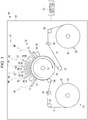
- Fig. 1 is a structural diagram schematically illustrating the structure of the liquid droplet ejecting apparatus.
- a liquid droplet ejecting apparatus 10 includes a medium sending section 11 that sends out a recording medium P by using a roll-to-roll process, an ink ejecting section 12 that includes a plurality of liquid droplet ejecting heads 13 and performs printing by ejecting UV ink to the recording medium P thus being sent out, and an ultraviolet ray radiating section 14 that radiates ultraviolet rays to cure the UV ink adhering to the recording medium P through the ink ejection.
- the liquid droplet ejecting apparatus 10 includes a maintenance section 15 that performs maintenance for the plurality of liquid droplet ejecting heads 13, a safety cover 16 that covers those constituent apparatuses, and a control section 17 that integrally controls those constituent apparatuses.
- the material for the recording medium P is not particularly limited, and various materials such as paper-based or film-based materials may be used.
- the medium sending section 11 includes a rotary drum 21 that is a main body, a feeding unit 22 that feeds the recording medium P in a roll shape toward the rotary drum 21, and a take-up unit 23 that takes up, into a roll shape, the recording medium P which is sent from the rotary drum 21 and is subjected to printing. Further, the medium sending section 11 includes an upstream intermediate roller 24, feeding rollers 25, and a send-in roller 26 that are located between the feeding unit 22 and the rotary drum 21. Similarly, the medium sending section 11 includes a send-out roller 27, discharging rollers 28, and a downstream intermediate roller 29 that are located between the rotary drum 21 and the take-up unit 23.
- the rotary drum 21 is formed in a freely rotatable fashion, and rotates with a frictional force of the recording medium P that is being sent out by the feeding rollers 25 and the discharging rollers 28.
- An encoder (not shown) is provided to a shaft 31 of the rotary drum 21.
- the feeding unit 22 includes a feeding reel 33 around which the recording medium P is wound, and rotates through driving of a motor in synchronization with the sending out of the recording medium P by the feeding rollers 25, thereby feeding the recording medium P.
- the upstream intermediate roller 24 is a freely rotatable roller, and changes the route of the recording medium P fed from the feeding unit 22 toward the feeding rollers 25.
- the feeding rollers 25 are nip rollers to be driven by a motor, and send out the recording medium P so that the rotary drum 21 rotates at a predetermined rotational speed (circumferential speed) based on a detection result from the encoder of the rotary drum 21.
- the send-in roller 26 is a freely rotatable roller, and changes the route of the recording medium P sent from the feeding rollers 25 so that the recording medium P is wound around the rotary drum 21.
- the send-out roller 27 is a freely rotatable roller, and changes the route of the recording medium P sent from the rotary drum 21 toward the discharging rollers 28.
- the discharging rollers 28 are nip rollers to be driven by a motor, and send out the recording medium P while applying a predetermined back tension to the recording medium P wound around the rotary drum 21.
- the downstream intermediate roller 29 is a freely rotatable roller, and changes the route of the recording medium P sent from the discharging rollers 28 toward the take-up unit 23.
- the take-up unit 23 includes a take-up reel 35 that takes up the recording medium P, and rotates through driving of a motor in synchronization with the sending out of the recording medium P by the discharging rollers 28, thereby taking up the recording medium P.
- the recording medium P is sent out along the outer peripheral surface of the rotary drum 21 as the rotary drum 21 rotates.
- the ink ejecting section 12 (plurality of liquid droplet ejecting heads 13) faces an upper part of the outer peripheral surface of the rotary drum 21 with a predetermined gap secured therebetween, and ejects UV ink onto (performs printing on) the recording medium P thus being sent out. That is, the rotary drum 21 functions as a platen that supports the recording medium P to constitute a part of the sending route thereof and faces the ink ejecting section 12 across the recording medium P.
- the ink ejecting section 12 includes six liquid droplet ejecting heads 13 arrayed along the outer peripheral surface of the rotary drum 21.
- the six liquid droplet ejecting heads 13 correspond to UV inks of six colors, and are arranged in the order of white, yellow, cyan, magenta, black, and clear (transparent) from the upstream side in the sending direction of the recording medium P (hereinafter referred to simply as "sending direction").
- the yellow, cyan, magenta, and black UV inks are used for forming color images, and the white UV ink is used as a background color for a transparent recording medium P or the like.
- the clear UV ink is superimposed on color images at the time of printing, thereby imparting a gloss, matte, or other appearance.
- Each liquid droplet ejecting head 13 has two nozzle arrays 37 (see Fig. 2 ) that are positionally shifted from each other by a half nozzle pitch.
- the two nozzle arrays 37 extend in a direction (sheet width direction) orthogonal to the sending direction of the recording medium P, that is, in a depth direction of the drawing sheet of Fig. 1 .
- a color image is printed by selectively driving (ejecting ink from) the plurality of liquid droplet ejecting heads 13 for the recording medium P that is being sent out at a constant speed by the rotary drum 21.
- the ultraviolet ray radiating section 14 includes six radiating units 39 corresponding to the six liquid droplet ejecting heads 13. Each radiating unit 39 is arranged on the downstream side in the sending direction with respect to the corresponding liquid droplet ejecting head 13, and the six liquid droplet ejecting heads 13 and the six radiating units 39 are alternately arranged in the sending direction. Three radiating units 39 corresponding to the yellow, cyan, and magenta liquid droplet ejecting heads 13 out of the six radiating units 39 are used for temporarily curing UV ink.
- Three radiating units 39 corresponding to the white, black, and clear liquid droplet ejecting heads 13 out of the six radiating units 39 are used for completely curing UV ink.
- the radiating units 39 for temporary curing temporarily cure UV ink that has landed on the recording medium P so that the UV ink spreads under desired conditions.
- the radiating units 39 for complete curing completely cure the UV ink that has landed on the recording medium P.
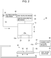
- the maintenance section 15 includes six maintenance units 40 corresponding to the six liquid droplet ejecting heads 13. Each maintenance unit 40 is arranged on the far side of the drawing sheet of Fig. 1 with respect to the corresponding liquid droplet ejecting head 13. Each maintenance unit 40 performs maintenance such as cleaning, wiping, and capping for the liquid droplet ejecting head 13. Further, the maintenance section 15 includes a cleaning liquid supplying apparatus 60 that supplies cleaning liquid to the six liquid droplet ejecting heads 13 as appropriate at the time of wiping (see Fig. 2 ). Description is given below taking as an example a maintenance unit 40 which the liquid droplet ejecting head 13 faces in a downward posture.
- each maintenance unit 40 includes a body unit 41 that performs wiping and capping for the liquid droplet ejecting head 13, a body moving mechanism 42 that moves the body unit 41 in a direction orthogonal to the nozzle array 37 of the liquid droplet ejecting head 13, a head moving mechanism 43 that moves the liquid droplet ejecting head 13 between a printing position where the liquid droplet ejecting head 13 faces the rotary drum 21 and a maintenance position where the liquid droplet ejecting head 13 faces the body unit 41, and a head raising/lowering mechanism 44 that is incorporated in the head moving mechanism 43 and raises/lowers the liquid droplet ejecting head 13.
- the maintenance unit 40 includes an ink pressurizing mechanism 46 that pressurizes UV ink to be supplied to the liquid droplet ejecting head 13, and a cleaning liquid ejecting section 47 that supplies cleaning liquid to the liquid droplet ejecting head 13 at the time of wiping.
- the cleaning liquid ejecting section 47 is connected to the cleaning liquid supplying apparatus 60.
- Those constituent apparatuses are controlled by the control section 17.
- a "wiping apparatus" includes the body unit 41, the body moving mechanism 42, and the head raising/lowering mechanism 44.
- the body unit 41 includes a unit base 51 formed so as to be freely movable in the direction orthogonal to the nozzle array 37 of the liquid droplet ejecting head 13, a pair of head caps 52 provided on the unit base 51, and a wiper 53 provided upright at the end of the unit base 51.
- the body moving mechanism 42 reciprocally moves the body unit 41 in the direction orthogonal to the nozzle array 37 when a nozzle surface 13a of the liquid droplet ejecting head 13 is wiped with the wiper 53. Further, the body moving mechanism 42 moves the head caps 52 to a position immediately below the liquid droplet ejecting head 13.
- the head raising/lowering mechanism 44 raises/lowers, with the maintenance position set as a home position of maintenance, the liquid droplet ejecting head 13 between the home position, a wiping position where the wiper 53 is pressed against the liquid droplet ejecting head 13, a cleaning position where the liquid droplet ejecting head 13 is brought closer to the head caps 52 at the time of pressure cleaning described later, and a capping position where the nozzle surface 13a is brought into contact with the head caps 52.
- the ink pressurizing mechanism 46 pressurizes UV ink to be supplied to the liquid droplet ejecting head 13, thereby forcefully ejecting the UV ink from nozzles 37a of the liquid droplet ejecting head 13.
- the ink pressurizing mechanism 46 is formed of a pump or the like that is connected via a three-way valve 56 to an ink supplying tube 55 connected to the liquid droplet ejecting head 13.
- the cleaning liquid ejecting section 47 causes cleaning liquid to adhere to the side surface of the liquid droplet ejecting head 13 prior to the wiping operation with the wiper 53.
- the side surface is a surface of the liquid droplet ejecting head 13 on a side adjacent to the nozzle surface 13a of the head.
- the cleaning liquid ejecting section 47 is arranged near the side surface of the liquid droplet ejecting head 13 which has moved to the wiping position, and is extends along at least part of the side surface of the liquid droplet ejecting head 13.
- an individual opening/closing valve 68 see Fig.
- the cleaning liquid ejecting section 47 is a component of the maintenance unit 40, and is also a component of the cleaning liquid supplying apparatus 60.
- a control system for maintenance is described, and a maintenance operation to be controlled by the control system is briefly described.
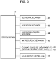
- the body moving mechanism 42, the head moving mechanism 43, the head raising/lowering mechanism 44, and the ink pressurizing mechanism 46 are connected to the control section 17. Further, the cleaning liquid supplying apparatus 60 and the liquid droplet ejecting head 13 are connected to the control section 17.
- the maintenance operation is performed in the order of wiping, pressure cleaning, finish wiping, and flushing.
- capping is performed.
- the control section 17 drives the head moving mechanism 43 to move the liquid droplet ejecting head 13 from the printing position to the maintenance position. Then, the control section 17 drives the head raising/lowering mechanism 44 to move the liquid droplet ejecting head 13 to the wiping position. At the timing when the liquid droplet ejecting head 13 has moved to the wiping position, the control section 17 opens the individual opening/closing valve 68 so as to cause cleaning liquid to adhere to the liquid droplet ejecting head 13 via the cleaning liquid ejecting section 47. Then, the control section 17 drives the body moving mechanism 42 to wipe the nozzle surface 13a with the wiper 53.
- the wiper 53 is reciprocally moved a plurality of times to mainly remove foreign substances adhering to the nozzle surface 13a.
- the cleaning liquid ejecting section 47 ejects the cleaning liquid every time the wiper 53 performs one reciprocal movement.
- the control section 17 drives the head raising/lowering mechanism 44 to move the liquid droplet ejecting head 13 to the cleaning position, and also drives the body moving mechanism 42 so as to cause the head caps 52 to face a portion immediately below the nozzle arrays 37 of the liquid droplet ejecting head 13.
- the control section 17 drives the ink pressurizing mechanism 46 to pressurize UV ink so as to forcefully eject the UV ink from all the nozzles 37a of the liquid droplet ejecting head 13. In this manner, an air bubble or cleaning liquid which has entered the nozzles 37a at the time of wiping is removed. In the pressure cleaning, the liquid droplet ejecting head 13 is not driven.
- finish wiping is performed with the wiper 53 through the procedure of the wiping described above.
- the wiper 53 is caused to perform one reciprocal movement so as to wipe the UV ink adhering to the nozzle surface 13a.
- the control section 17 drives the liquid droplet ejecting head 13 to perform flushing (discarding ejection) with the head caps 52 located immediately below the nozzle arrays 37 of the liquid droplet ejecting head 13. In this manner, appropriate menisci are formed in the nozzles 37a of the liquid droplet ejecting head 13.
- the control section 17 returns the liquid droplet ejecting head 13 and the body unit 41 to the initial positions, and the series of processes in the maintenance operation is completed.
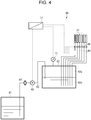
- the cleaning liquid supplying apparatus 60 supplies cleaning liquid to the six cleaning liquid ejecting sections 47 of the six maintenance units 40.
- the cleaning liquid supplying apparatus 60 includes a main storage section 61 (first storage section) that stores cleaning liquid, a pressure-accumulating sub-storage section 62 (second storage section) that is connected to the main storage section 61 via a main flow channel 63 (first flow channel), and the six cleaning liquid ejecting sections 47 that are connected to the sub-storage section 62 via six individual flow channels 64.
- the cleaning liquid supplying apparatus 60 includes a cleaning liquid pump 66 (liquid sending section) that is provided midway along the main flow channel 63 and sends the cleaning liquid in the main storage section 61 to the sub-storage section 62, a filter 67 that is provided midway along the main flow channel 63, and the six individual opening/closing valves 68 (individual flow channel opening/closing sections) that open/close the individual flow channels 64, respectively. Those components are controlled by the control section 17.
- a cleaning liquid pump 66 liquid sending section
- filter 67 that is provided midway along the main flow channel 63
- the six individual opening/closing valves 68 individual flow channel opening/closing sections
- the main storage section 61 is formed of a stainless open tank in consideration of corrosion that may be caused by the cleaning liquid.
- the sub-storage section 62 is formed of a stainless sealed tank.
- an air reservoir 62a is formed at an upper part thereof, and a liquid reservoir 62b is formed at a lower part thereof.
- the sub-storage section 62 is arranged at a higher position than the main storage section 61.
- the cleaning liquid pump 66 pumps up the cleaning liquid in the main storage section 61 into the sub-storage section 62, and increases the pressure in the sub-storage section 62.
- a pressure detecting section 71 (pressure sensor) that detects the internal pressure of the sub-storage section 62 is provided on the sub-storage section 62 so as to communicate with the air reservoir 62a.
- the pressure detecting section 71 is connected to the control section 17.
- the main flow channel 63 is formed of, for example, a chemical-resistant tube.
- the cleaning liquid pump 66 and the filter 67 are connected to the main flow channel 63 via couplings (not shown).
- the downstream portion of the main flow channel 63 extends deeply into the sub-storage section 62, and is open to the liquid reservoir 62b. This configuration prevents formation of waves in the sub-storage section 62 or entry of air into the cleaning liquid when the cleaning liquid is sent to the sub-storage section 62.
- the cleaning liquid pump 66 is, for example, a small diaphragm pump.
- the cleaning liquid pump 66 is connected to the control section 17, and the control section 17 controls driving of the cleaning liquid pump 66 based on a detection result from the pressure detecting section 71.
- each individual flow channel 64 is formed of a chemical-resistant tube.
- the upstream end of the individual flow channel 64 is open to the liquid reservoir 62b of the sub-storage section 62.
- Each individual opening/closing valve 68 is, for example, a chemical-resistant electromagnetic valve (two-way valve). As described above, the cleaning liquid is ejected from the cleaning liquid ejecting section 47 by opening the individual opening/closing valve 68.
- Each cleaning liquid ejecting section 47 is formed of, for example, a stainless pipe, and has the plurality of ejecting ports 47a formed along an extending direction.
- the pipe-shaped cleaning liquid ejecting section 47 is formed so as to have a diameter that is sufficiently larger than that of the individual flow channel 64 for the cleaning liquid ejecting section 47 to perform a manifold function.
- the cleaning liquid ejecting section 47 has a length corresponding to the length of the liquid droplet ejecting head 13 in the longitudinal direction. As described above, the cleaning liquid ejecting section 47 is arranged near the side surface of the liquid droplet ejecting head 13 which has moved to the wiping position.
- the control section 17 controls the cleaning liquid pump 66 so that the pressure in the air reservoir 62a of the sub-storage section 62 becomes a predetermined pressure. Specifically, the control section 17 controls the cleaning liquid pump 66 so that the pressure in the air reservoir 62a becomes a predetermined pressure based on the detection result from the pressure detecting section 71. For example, an upper threshold and a lower threshold are set for the predetermined pressure in the air reservoir 62a, and the control section 17 activates the cleaning liquid pump 66 when the pressure has reached the lower threshold, and stops the cleaning liquid pump 66 when the pressure has reached the upper threshold.
- the control section 17 opens the corresponding individual opening/closing valve 68.
- the cleaning liquid in the sub-storage section 62 is sent to the cleaning liquid ejecting section 47 under pressure, and is ejected from the plurality of ejecting ports 47a.
- the liquid droplet ejecting apparatus 10 of the embodiment is intended to drive the six maintenance units 40 simultaneously in periodic maintenance (periodic cleaning). Therefore, the cleaning liquid is simultaneously supplied to the six cleaning liquid ejecting sections 47 by simultaneously opening the six individual opening/closing valves 68.
- the sub-storage section 62 is replenished with the cleaning liquid in the main storage section 61 and the pressure in the sub-storage section 62 becomes a predetermined pressure through the driving of the cleaning liquid pump 66. Therefore, the cleaning liquid in the sub-storage section 62 is sent to the cleaning liquid ejecting section 47 under pressure by opening the individual opening/closing valve 68.
- a film that partitions the liquid reservoir 62b and the air reservoir 62a from each other in an air-tight fashion may be provided. With this film, air can be prevented from being mixed into the cleaning liquid in the sub-storage section 62, thereby facilitating volume control for the air reservoir 62a.
- the cleaning liquid supplying apparatus 60A of the second embodiment includes, in addition to the components of the first embodiment, a cleaning liquid returning section 73 that includes a return flow channel 74 and returns the cleaning liquid in the sub-storage section 62 to the main storage section 61, and an atmosphere opening/closing section 75 that includes an air flow channel 76 and opens/closes the air reservoir 62a of the sub-storage section 62 to/from the atmosphere.
- the cleaning liquid returning section 73 includes the return flow channel 74 through which the cleaning liquid in the sub-storage section 62 is returned to the main storage section 61, and a return opening/closing valve 77 (return flow channel opening/closing section) that opens/closes the return flow channel 74.
- the return flow channel 74 is formed of a chemical-resistant tube, and is connected on the upstream side to the sub-storage section 62 and also connected on the downstream side to the main flow channel 63 between the filter 67 and the cleaning liquid pump 66.
- the upstream end of the return flow channel 74 is open at a position corresponding to a reference liquid level (predetermined liquid level) of the liquid reservoir 62b.
- the filter 67 can be made substantially free of maintenance.
- the downstream end of the return flow channel 74 may be connected directly to the main storage section 61, or may be connected to a waste liquid tank (not shown).
- the return opening/closing valve 77 is a chemical-resistant electromagnetic valve.
- the return opening/closing valve 77 is connected to the control section 17, and the control section 17 opens the return opening/closing valve 77 when the cleaning liquid pump 66 is stopped. In a state in which the cleaning liquid pump 66 is stopped, the pressure in the air reservoir 62a has reached the upper threshold.
- the return opening/closing valve 77 is opened, the cleaning liquid in the sub-storage section 62 flows toward the main storage section 61 via the return flow channel 74 owing to the pressure in the air reservoir 62a.
- the description "when the cleaning liquid pump 66 is stopped" in this case may refer to a state in which all the individual opening/closing valves 68 are closed and the pump is stopped while the wiper 53 is performing one reciprocal movement, or may refer to a state in which the pump is stopped after the wiper 53 has performed reciprocal movement a plurality of times, that is, after the wiping operation is completed. Further, the above description may refer to a state in which the pump is stopped while the operation of the cleaning liquid supplying apparatus 60A or the liquid droplet ejecting apparatus 10 is stopped.
- the atmosphere opening/closing section 75 includes the air flow channel 76 that opens the air reservoir 62a of the sub-storage section 62 to the atmosphere, and an air opening/closing valve 78 (air flow channel opening/closing section) that opens/closes the air flow channel 76.
- the air flow channel 76 is formed of a chemical-resistant tube, and is connected on the downstream side to the sub-storage section 62 and also connected on the upstream side to the main storage section 61.
- the downstream end of the air flow channel 76 is open to the air reservoir 62a of the sub-storage section 62, and the upstream end of the air flow channel 76 is open to an atmospheric-pressure air reservoir 61a that is formed at the upper end of the main storage section 61.
- the air opening/closing valve 78 is a chemical-resistant electromagnetic valve.
- the air opening/closing valve 78 is connected to the control section 17, and the control section 17 opens the air opening/closing valve 78 at the timing when the pressure in the air reservoir 62a is decreased to the atmospheric pressure after the return opening/closing valve 77 is opened.
- the sending out of the cleaning liquid to be returned from the sub-storage section 62 to the main storage section 61 is switched in midstream from the sending out of the cleaning liquid with the pressure in the air reservoir 62a to the sending out of the cleaning liquid with a siphon operation.
- the liquid level of the liquid reservoir 62b of the sub-storage section 62 is securely restored to the reference liquid level.
- the configuration in which the upstream end of the air flow channel 76 is connected to the main storage section 61 is intended to prevent the vaporized cleaning liquid from being released to the atmosphere.
- the upstream end of the air flow channel 76 may be connected to a waste liquid tank or an exhaust air processing facility (not shown). As long as the vaporized cleaning liquid causes no problem such as air pollution, the upstream end of the air flow channel 76 may simply be open to the atmosphere.
- the operation for supplying cleaning liquid to the cleaning liquid ejecting section 47 by the control section 17 is similar to that of the first embodiment.
- the operation for returning cleaning liquid is performed in the following manner.
- the control section 17 first opens the return opening/closing valve 77.
- the returning of cleaning liquid from the sub-storage section 62 to the main storage section 61 is started.
- the pressure in the sub-storage section 62 (air reservoir 62a) is gradually decreased.
- the control section 17 opens the air opening/closing valve 78.
- the main storage section 61 is arranged at a lower position than the sub-storage section 62, and due to the flow of cleaning liquid up until that time point, the air in the return flow channel 74 has flowed out, and hence the return flow channel 74 is filled with the cleaning liquid.
- the air opening/closing valve 78 is opened, the flow of cleaning liquid continues while being switched from the flow with the pressure in the air reservoir 62a to the flow with the siphon operation.
- the termination of the siphon operation (stop of the returning of cleaning liquid) is controlled on a time basis from the time point when the pressure detecting section 71 has detected the predetermined pressure close to the atmospheric pressure. After a predetermined period of time has elapsed from the time point when the pressure detecting section 71 has detected the predetermined pressure, the control section 17 closes the return opening/closing valve 77 and the air opening/closing valve 78, and completes the operation for returning cleaning liquid.
- the operation for returning cleaning liquid is performed when the cleaning liquid pump 66 is stopped, and hence the liquid reservoir 62b and the air reservoir 62a of the sub-storage section 62 can be reset to the original conditions.
- the liquid level of the liquid reservoir 62b of the sub-storage section 62 can be reset to the reference liquid level. That is, the volumes of the liquid reservoir 62b and the air reservoir 62a can be reset to desired volumes even if the air in the air reservoir 62a is mixed into the cleaning liquid in the liquid reservoir 62b.
- the operation for returning cleaning liquid is performed by using the pressure in the air reservoir 62a and the siphon operation, and hence the structure for the returning operation can be simplified.
- the cleaning liquid supplying apparatus 60A that is free of maintenance and is reduced in cost can be provided.
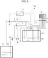
- a cleaning liquid supplying apparatus 60B according to a third embodiment is described with reference to Fig. 6 .
- differences from the first embodiment are mainly described.
- a sub-storage section 62B has a structure different from that of the sub-storage section 62 of the first embodiment.
- a piston-like member 81 is provided in the air reservoir 62a in a freely ascending/descending fashion.
- a position detecting section 82 that detects the position of the piston-like member 81 in the ascending/descending direction is provided.
- the piston-like member 81 is formed of a chemical-resistant resin or the like, and includes a piston body 84 and a rod portion 85 extending from the piston body 84.
- the piston body 84 is provided on the inner peripheral surface of the sub-storage section 62B in an air-tight fashion and in a freely ascending/descending fashion. In this case, the piston-like member 81 ascends/descends with a balance between the weight of the piston-like member 81 and the pressure in the air reservoir 62a.
- the position detecting section 82 is provided in place of the pressure detecting section 71, and is constituted by a pair of upper/lower photosensors 87a and 87b.
- the pair of photosensors 87a and 87b is arranged vertically so as to face the rod portion 85 of the ascending/descending piston-like member 81.
- the position of the upper photosensor 87a corresponds to the upper threshold described above
- the position of the lower photosensor 87b corresponds to the lower threshold described above.
- the control section 17 activates the cleaning liquid pump 66 when the lower photosensor 87b has detected that the rod portion 85 is “absent”, and stops the cleaning liquid pump 66 when the upper photosensor 87a has detected that the rod portion 85 is "present”.
- the pressure in the sub-storage section 62B is maintained at the predetermined pressure, and the cleaning liquid in the sub-storage section 62B is sent to the cleaning liquid ejecting section 47 under pressure by opening the individual opening/closing valve 68.
- the cleaning liquid pump 66 is controlled based on the detection result from the position detecting section 82, and hence the pressure in the sub-storage section 62B can indirectly be controlled so as to become the predetermined pressure. Even if an abrupt pressure fluctuation has occurred on the cleaning liquid pump 66 (diaphragm pump) side or the cleaning liquid ejecting section 47 side, the pressure fluctuation can be absorbed by the ascending/descending of the piston-like member 81. Thus, the cleaning liquid can stably be supplied to each cleaning liquid ejecting section 47.
- a linear encoder As the position detecting section 82, a linear encoder, a microswitch or a proximity switch may be used.
Landscapes
- Ink Jet (AREA)
- Inking, Control Or Cleaning Of Printing Machines (AREA)
Applications Claiming Priority (1)
| Application Number | Priority Date | Filing Date | Title |
|---|---|---|---|
| JP2016057498A JP6686592B2 (ja) | 2016-03-22 | 2016-03-22 | 洗浄液供給装置およびこれを備えた液滴吐出装置 |
Publications (2)
| Publication Number | Publication Date |
|---|---|
| EP3222425A1 EP3222425A1 (en) | 2017-09-27 |
| EP3222425B1 true EP3222425B1 (en) | 2019-02-20 |
Family
ID=58401491
Family Applications (1)
| Application Number | Title | Priority Date | Filing Date |
|---|---|---|---|
| EP17162360.6A Active EP3222425B1 (en) | 2016-03-22 | 2017-03-22 | Cleaning liquid supplying apparatus and liquid droplet ejecting apparatus including the same |
Country Status (4)
| Country | Link |
|---|---|
| US (1) | US9878547B2 (ja) |
| EP (1) | EP3222425B1 (ja) |
| JP (1) | JP6686592B2 (ja) |
| CN (1) | CN107215100B (ja) |
Families Citing this family (3)
| Publication number | Priority date | Publication date | Assignee | Title |
|---|---|---|---|---|
| KR102662361B1 (ko) * | 2019-02-01 | 2024-04-30 | 엑스티피엘 에스.에이. | 유체 프린팅 방법 |
| JP2020128037A (ja) * | 2019-02-08 | 2020-08-27 | 東レエンジニアリング株式会社 | インクジェット塗布装置及びインクジェットヘッドの洗浄方法 |
| CN112339435A (zh) * | 2019-10-28 | 2021-02-09 | 广东聚华印刷显示技术有限公司 | 喷墨打印系统、清洗方法及清洗装置 |
Family Cites Families (18)
| Publication number | Priority date | Publication date | Assignee | Title |
|---|---|---|---|---|
| DE3726671A1 (de) * | 1986-12-23 | 1988-07-07 | Robotron Veb K | Verfahren und einrichtung zur erhaltung der funktionsfaehigkeit eines tintenstrahldruckers |
| JP3713960B2 (ja) * | 1998-06-11 | 2005-11-09 | ブラザー工業株式会社 | インクジェット記録装置 |
| US6742882B2 (en) * | 2001-06-26 | 2004-06-01 | Brother Kogyo Kabushiki Kaisha | Air purge device for ink jet recording apparatus |
| JP2004188664A (ja) * | 2002-12-09 | 2004-07-08 | Sharp Corp | インクジェットプリンタ |
| CN1771133A (zh) * | 2004-01-14 | 2006-05-10 | 精工爱普生株式会社 | 液体喷射装置 |
| JP2006015637A (ja) * | 2004-07-02 | 2006-01-19 | Fuji Photo Film Co Ltd | インクジェット記録装置 |
| KR100694121B1 (ko) * | 2005-06-02 | 2007-03-12 | 삼성전자주식회사 | 잉크젯 화상형성장치 및 노즐부 클리닝방법 |
| JP4874605B2 (ja) * | 2005-09-12 | 2012-02-15 | 株式会社リコー | インク供給容器と記録装置及びインク供給方法 |
| GB2447919B (en) * | 2007-03-27 | 2012-04-04 | Linx Printing Tech | Ink jet printing |
| JP4321617B2 (ja) * | 2007-03-29 | 2009-08-26 | セイコーエプソン株式会社 | 機能液供給装置および液滴吐出装置、並びに電気光学装置の製造方法 |
| JP5191422B2 (ja) * | 2009-03-13 | 2013-05-08 | 富士フイルム株式会社 | 吐出面清掃装置及び液体吐出装置並びに吐出面清掃方法 |
| JP2011073295A (ja) * | 2009-09-30 | 2011-04-14 | Fujifilm Corp | ヘッド洗浄装置及び画像記録装置 |
| CN102101385B (zh) * | 2009-12-16 | 2012-11-07 | 北大方正集团有限公司 | 喷头清洁装置及方法 |
| JP5938891B2 (ja) * | 2011-12-20 | 2016-06-22 | セイコーエプソン株式会社 | 印刷装置、及び、液体移送方法 |
| JP2014080008A (ja) * | 2012-09-28 | 2014-05-08 | Dainippon Screen Mfg Co Ltd | 印刷装置および液体供給方法 |
| JP6127587B2 (ja) | 2013-03-05 | 2017-05-17 | セイコーエプソン株式会社 | 液体吐出装置および吐出ヘッドの洗浄方法 |
| JP6098296B2 (ja) * | 2013-03-29 | 2017-03-22 | ブラザー工業株式会社 | 液体吐出装置 |
| JP6253470B2 (ja) * | 2014-03-25 | 2017-12-27 | 株式会社ミマキエンジニアリング | ヘッド洗浄装置、インクジェットプリンターおよびヘッド洗浄方法 |
-
2016
- 2016-03-22 JP JP2016057498A patent/JP6686592B2/ja active Active
-
2017
- 2017-03-17 US US15/462,407 patent/US9878547B2/en active Active
- 2017-03-17 CN CN201710164771.8A patent/CN107215100B/zh active Active
- 2017-03-22 EP EP17162360.6A patent/EP3222425B1/en active Active
Non-Patent Citations (1)
| Title |
|---|
| None * |
Also Published As
| Publication number | Publication date |
|---|---|
| EP3222425A1 (en) | 2017-09-27 |
| JP2017170700A (ja) | 2017-09-28 |
| CN107215100A (zh) | 2017-09-29 |
| US9878547B2 (en) | 2018-01-30 |
| US20170274660A1 (en) | 2017-09-28 |
| JP6686592B2 (ja) | 2020-04-22 |
| CN107215100B (zh) | 2020-06-30 |
Similar Documents
| Publication | Publication Date | Title |
|---|---|---|
| US8033657B2 (en) | Image forming apparatus including liquid discharge head unit | |
| JP5163286B2 (ja) | 液体吐出装置及び画像投射装置 | |
| US8303060B2 (en) | Image forming apparatus | |
| JP2013173343A (ja) | 画像形成装置 | |
| US20080174631A1 (en) | Image forming apparatus having a plurality of liquid discharge heads | |
| EP3222425B1 (en) | Cleaning liquid supplying apparatus and liquid droplet ejecting apparatus including the same | |
| WO2014009232A1 (en) | Printer configured for efficient air bubble removal | |
| JP4944296B2 (ja) | インクジェット記録装置及び吐出回復方法 | |
| JP5272947B2 (ja) | 画像形成装置 | |
| JP5402033B2 (ja) | 画像形成装置 | |
| JP5434673B2 (ja) | 液体噴射装置 | |
| JP5636823B2 (ja) | 画像形成装置 | |
| JP5764991B2 (ja) | 画像形成装置 | |
| JPH08276604A (ja) | インクジェットプリント装置およびインクジェットヘッドの回復方法 | |
| JP4280569B2 (ja) | インクジェット記録装置 | |
| JP2007015374A (ja) | インクジェットプリンタ及びインクジェットプリンタにおける気泡除去方法 | |
| JP7116917B2 (ja) | 液体を吐出する装置 | |
| JP2010105297A (ja) | 画像形成装置 | |
| US9278535B2 (en) | Recording head recovery mechanism, inkjet recording apparatus, and recording head recovery method | |
| US9469121B2 (en) | Inkjet printer | |
| US20220063282A1 (en) | Liquid ejecting apparatus and maintenance method of liquid ejecting apparatus | |
| JP2011143614A (ja) | 画像形成装置 | |
| JP2010046806A (ja) | 画像形成装置 | |
| JP5515634B2 (ja) | 画像形成装置 | |
| JP5440130B2 (ja) | 画像形成装置 |
Legal Events
| Date | Code | Title | Description |
|---|---|---|---|
| PUAI | Public reference made under article 153(3) epc to a published international application that has entered the european phase |
Free format text: ORIGINAL CODE: 0009012 |
|
| STAA | Information on the status of an ep patent application or granted ep patent |
Free format text: STATUS: THE APPLICATION HAS BEEN PUBLISHED |
|
| AK | Designated contracting states |
Kind code of ref document: A1 Designated state(s): AL AT BE BG CH CY CZ DE DK EE ES FI FR GB GR HR HU IE IS IT LI LT LU LV MC MK MT NL NO PL PT RO RS SE SI SK SM TR |
|
| AX | Request for extension of the european patent |
Extension state: BA ME |
|
| STAA | Information on the status of an ep patent application or granted ep patent |
Free format text: STATUS: REQUEST FOR EXAMINATION WAS MADE |
|
| 17P | Request for examination filed |
Effective date: 20180220 |
|
| RBV | Designated contracting states (corrected) |
Designated state(s): AL AT BE BG CH CY CZ DE DK EE ES FI FR GB GR HR HU IE IS IT LI LT LU LV MC MK MT NL NO PL PT RO RS SE SI SK SM TR |
|
| RIC1 | Information provided on ipc code assigned before grant |
Ipc: B41J 2/165 20060101AFI20180724BHEP Ipc: B41J 25/00 20060101ALN20180724BHEP |
|
| GRAP | Despatch of communication of intention to grant a patent |
Free format text: ORIGINAL CODE: EPIDOSNIGR1 |
|
| STAA | Information on the status of an ep patent application or granted ep patent |
Free format text: STATUS: GRANT OF PATENT IS INTENDED |
|
| INTG | Intention to grant announced |
Effective date: 20180914 |
|
| GRAS | Grant fee paid |
Free format text: ORIGINAL CODE: EPIDOSNIGR3 |
|
| GRAA | (expected) grant |
Free format text: ORIGINAL CODE: 0009210 |
|
| STAA | Information on the status of an ep patent application or granted ep patent |
Free format text: STATUS: THE PATENT HAS BEEN GRANTED |
|
| AK | Designated contracting states |
Kind code of ref document: B1 Designated state(s): AL AT BE BG CH CY CZ DE DK EE ES FI FR GB GR HR HU IE IS IT LI LT LU LV MC MK MT NL NO PL PT RO RS SE SI SK SM TR |
|
| REG | Reference to a national code |
Ref country code: GB Ref legal event code: FG4D |
|
| REG | Reference to a national code |
Ref country code: CH Ref legal event code: EP |
|
| REG | Reference to a national code |
Ref country code: DE Ref legal event code: R096 Ref document number: 602017002162 Country of ref document: DE |
|
| REG | Reference to a national code |
Ref country code: AT Ref legal event code: REF Ref document number: 1097667 Country of ref document: AT Kind code of ref document: T Effective date: 20190315 |
|
| REG | Reference to a national code |
Ref country code: IE Ref legal event code: FG4D |
|
| REG | Reference to a national code |
Ref country code: LT Ref legal event code: MG4D Ref country code: NL Ref legal event code: MP Effective date: 20190220 |
|
| PG25 | Lapsed in a contracting state [announced via postgrant information from national office to epo] |
Ref country code: NO Free format text: LAPSE BECAUSE OF FAILURE TO SUBMIT A TRANSLATION OF THE DESCRIPTION OR TO PAY THE FEE WITHIN THE PRESCRIBED TIME-LIMIT Effective date: 20190520 Ref country code: PT Free format text: LAPSE BECAUSE OF FAILURE TO SUBMIT A TRANSLATION OF THE DESCRIPTION OR TO PAY THE FEE WITHIN THE PRESCRIBED TIME-LIMIT Effective date: 20190620 Ref country code: FI Free format text: LAPSE BECAUSE OF FAILURE TO SUBMIT A TRANSLATION OF THE DESCRIPTION OR TO PAY THE FEE WITHIN THE PRESCRIBED TIME-LIMIT Effective date: 20190220 Ref country code: SE Free format text: LAPSE BECAUSE OF FAILURE TO SUBMIT A TRANSLATION OF THE DESCRIPTION OR TO PAY THE FEE WITHIN THE PRESCRIBED TIME-LIMIT Effective date: 20190220 Ref country code: ES Free format text: LAPSE BECAUSE OF FAILURE TO SUBMIT A TRANSLATION OF THE DESCRIPTION OR TO PAY THE FEE WITHIN THE PRESCRIBED TIME-LIMIT Effective date: 20190220 Ref country code: LT Free format text: LAPSE BECAUSE OF FAILURE TO SUBMIT A TRANSLATION OF THE DESCRIPTION OR TO PAY THE FEE WITHIN THE PRESCRIBED TIME-LIMIT Effective date: 20190220 |
|
| PG25 | Lapsed in a contracting state [announced via postgrant information from national office to epo] |
Ref country code: HR Free format text: LAPSE BECAUSE OF FAILURE TO SUBMIT A TRANSLATION OF THE DESCRIPTION OR TO PAY THE FEE WITHIN THE PRESCRIBED TIME-LIMIT Effective date: 20190220 Ref country code: NL Free format text: LAPSE BECAUSE OF FAILURE TO SUBMIT A TRANSLATION OF THE DESCRIPTION OR TO PAY THE FEE WITHIN THE PRESCRIBED TIME-LIMIT Effective date: 20190220 Ref country code: LV Free format text: LAPSE BECAUSE OF FAILURE TO SUBMIT A TRANSLATION OF THE DESCRIPTION OR TO PAY THE FEE WITHIN THE PRESCRIBED TIME-LIMIT Effective date: 20190220 Ref country code: GR Free format text: LAPSE BECAUSE OF FAILURE TO SUBMIT A TRANSLATION OF THE DESCRIPTION OR TO PAY THE FEE WITHIN THE PRESCRIBED TIME-LIMIT Effective date: 20190521 Ref country code: IS Free format text: LAPSE BECAUSE OF FAILURE TO SUBMIT A TRANSLATION OF THE DESCRIPTION OR TO PAY THE FEE WITHIN THE PRESCRIBED TIME-LIMIT Effective date: 20190620 Ref country code: BG Free format text: LAPSE BECAUSE OF FAILURE TO SUBMIT A TRANSLATION OF THE DESCRIPTION OR TO PAY THE FEE WITHIN THE PRESCRIBED TIME-LIMIT Effective date: 20190520 Ref country code: RS Free format text: LAPSE BECAUSE OF FAILURE TO SUBMIT A TRANSLATION OF THE DESCRIPTION OR TO PAY THE FEE WITHIN THE PRESCRIBED TIME-LIMIT Effective date: 20190220 |
|
| REG | Reference to a national code |
Ref country code: AT Ref legal event code: MK05 Ref document number: 1097667 Country of ref document: AT Kind code of ref document: T Effective date: 20190220 |
|
| PG25 | Lapsed in a contracting state [announced via postgrant information from national office to epo] |
Ref country code: EE Free format text: LAPSE BECAUSE OF FAILURE TO SUBMIT A TRANSLATION OF THE DESCRIPTION OR TO PAY THE FEE WITHIN THE PRESCRIBED TIME-LIMIT Effective date: 20190220 Ref country code: DK Free format text: LAPSE BECAUSE OF FAILURE TO SUBMIT A TRANSLATION OF THE DESCRIPTION OR TO PAY THE FEE WITHIN THE PRESCRIBED TIME-LIMIT Effective date: 20190220 Ref country code: IT Free format text: LAPSE BECAUSE OF FAILURE TO SUBMIT A TRANSLATION OF THE DESCRIPTION OR TO PAY THE FEE WITHIN THE PRESCRIBED TIME-LIMIT Effective date: 20190220 Ref country code: RO Free format text: LAPSE BECAUSE OF FAILURE TO SUBMIT A TRANSLATION OF THE DESCRIPTION OR TO PAY THE FEE WITHIN THE PRESCRIBED TIME-LIMIT Effective date: 20190220 Ref country code: CZ Free format text: LAPSE BECAUSE OF FAILURE TO SUBMIT A TRANSLATION OF THE DESCRIPTION OR TO PAY THE FEE WITHIN THE PRESCRIBED TIME-LIMIT Effective date: 20190220 Ref country code: AL Free format text: LAPSE BECAUSE OF FAILURE TO SUBMIT A TRANSLATION OF THE DESCRIPTION OR TO PAY THE FEE WITHIN THE PRESCRIBED TIME-LIMIT Effective date: 20190220 Ref country code: SK Free format text: LAPSE BECAUSE OF FAILURE TO SUBMIT A TRANSLATION OF THE DESCRIPTION OR TO PAY THE FEE WITHIN THE PRESCRIBED TIME-LIMIT Effective date: 20190220 |
|
| REG | Reference to a national code |
Ref country code: DE Ref legal event code: R097 Ref document number: 602017002162 Country of ref document: DE |
|
| PG25 | Lapsed in a contracting state [announced via postgrant information from national office to epo] |
Ref country code: PL Free format text: LAPSE BECAUSE OF FAILURE TO SUBMIT A TRANSLATION OF THE DESCRIPTION OR TO PAY THE FEE WITHIN THE PRESCRIBED TIME-LIMIT Effective date: 20190220 Ref country code: SM Free format text: LAPSE BECAUSE OF FAILURE TO SUBMIT A TRANSLATION OF THE DESCRIPTION OR TO PAY THE FEE WITHIN THE PRESCRIBED TIME-LIMIT Effective date: 20190220 Ref country code: LU Free format text: LAPSE BECAUSE OF NON-PAYMENT OF DUE FEES Effective date: 20190322 |
|
| REG | Reference to a national code |
Ref country code: BE Ref legal event code: MM Effective date: 20190331 |
|
| PLBE | No opposition filed within time limit |
Free format text: ORIGINAL CODE: 0009261 |
|
| STAA | Information on the status of an ep patent application or granted ep patent |
Free format text: STATUS: NO OPPOSITION FILED WITHIN TIME LIMIT |
|
| PG25 | Lapsed in a contracting state [announced via postgrant information from national office to epo] |
Ref country code: AT Free format text: LAPSE BECAUSE OF FAILURE TO SUBMIT A TRANSLATION OF THE DESCRIPTION OR TO PAY THE FEE WITHIN THE PRESCRIBED TIME-LIMIT Effective date: 20190220 Ref country code: MC Free format text: LAPSE BECAUSE OF FAILURE TO SUBMIT A TRANSLATION OF THE DESCRIPTION OR TO PAY THE FEE WITHIN THE PRESCRIBED TIME-LIMIT Effective date: 20190220 |
|
| 26N | No opposition filed |
Effective date: 20191121 |
|
| PG25 | Lapsed in a contracting state [announced via postgrant information from national office to epo] |
Ref country code: IE Free format text: LAPSE BECAUSE OF NON-PAYMENT OF DUE FEES Effective date: 20190322 |
|
| PG25 | Lapsed in a contracting state [announced via postgrant information from national office to epo] |
Ref country code: BE Free format text: LAPSE BECAUSE OF NON-PAYMENT OF DUE FEES Effective date: 20190331 Ref country code: SI Free format text: LAPSE BECAUSE OF FAILURE TO SUBMIT A TRANSLATION OF THE DESCRIPTION OR TO PAY THE FEE WITHIN THE PRESCRIBED TIME-LIMIT Effective date: 20190220 |
|
| PG25 | Lapsed in a contracting state [announced via postgrant information from national office to epo] |
Ref country code: TR Free format text: LAPSE BECAUSE OF FAILURE TO SUBMIT A TRANSLATION OF THE DESCRIPTION OR TO PAY THE FEE WITHIN THE PRESCRIBED TIME-LIMIT Effective date: 20190220 |
|
| PG25 | Lapsed in a contracting state [announced via postgrant information from national office to epo] |
Ref country code: MT Free format text: LAPSE BECAUSE OF NON-PAYMENT OF DUE FEES Effective date: 20190322 |
|
| REG | Reference to a national code |
Ref country code: CH Ref legal event code: PL |
|
| PG25 | Lapsed in a contracting state [announced via postgrant information from national office to epo] |
Ref country code: CH Free format text: LAPSE BECAUSE OF NON-PAYMENT OF DUE FEES Effective date: 20200331 Ref country code: LI Free format text: LAPSE BECAUSE OF NON-PAYMENT OF DUE FEES Effective date: 20200331 |
|
| PG25 | Lapsed in a contracting state [announced via postgrant information from national office to epo] |
Ref country code: CY Free format text: LAPSE BECAUSE OF FAILURE TO SUBMIT A TRANSLATION OF THE DESCRIPTION OR TO PAY THE FEE WITHIN THE PRESCRIBED TIME-LIMIT Effective date: 20190220 |
|
| PG25 | Lapsed in a contracting state [announced via postgrant information from national office to epo] |
Ref country code: HU Free format text: LAPSE BECAUSE OF FAILURE TO SUBMIT A TRANSLATION OF THE DESCRIPTION OR TO PAY THE FEE WITHIN THE PRESCRIBED TIME-LIMIT; INVALID AB INITIO Effective date: 20170322 |
|
| PG25 | Lapsed in a contracting state [announced via postgrant information from national office to epo] |
Ref country code: MK Free format text: LAPSE BECAUSE OF FAILURE TO SUBMIT A TRANSLATION OF THE DESCRIPTION OR TO PAY THE FEE WITHIN THE PRESCRIBED TIME-LIMIT Effective date: 20190220 |
|
| PGFP | Annual fee paid to national office [announced via postgrant information from national office to epo] |
Ref country code: DE Payment date: 20240130 Year of fee payment: 8 Ref country code: GB Payment date: 20240201 Year of fee payment: 8 |
|
| PGFP | Annual fee paid to national office [announced via postgrant information from national office to epo] |
Ref country code: FR Payment date: 20240213 Year of fee payment: 8 |