EP3221231B1 - Applicateur pour appliquer un produit cosmetique, de maquillage ou de soin - Google Patents
Applicateur pour appliquer un produit cosmetique, de maquillage ou de soin Download PDFInfo
- Publication number
- EP3221231B1 EP3221231B1 EP15798095.4A EP15798095A EP3221231B1 EP 3221231 B1 EP3221231 B1 EP 3221231B1 EP 15798095 A EP15798095 A EP 15798095A EP 3221231 B1 EP3221231 B1 EP 3221231B1
- Authority
- EP
- European Patent Office
- Prior art keywords
- applicator
- handle
- longitudinal axis
- length
- cross
- Prior art date
- Legal status (The legal status is an assumption and is not a legal conclusion. Google has not performed a legal analysis and makes no representation as to the accuracy of the status listed.)
- Active
Links
- 239000002537 cosmetic Substances 0.000 title description 4
- 210000000744 eyelid Anatomy 0.000 claims description 15
- 238000004806 packaging method and process Methods 0.000 claims description 5
- 238000000034 method Methods 0.000 claims description 2
- 210000003811 finger Anatomy 0.000 description 9
- 210000003813 thumb Anatomy 0.000 description 5
- UQSXHKLRYXJYBZ-UHFFFAOYSA-N Iron oxide Chemical compound [Fe]=O UQSXHKLRYXJYBZ-UHFFFAOYSA-N 0.000 description 4
- 239000000835 fiber Substances 0.000 description 4
- 239000012528 membrane Substances 0.000 description 4
- 210000005224 forefinger Anatomy 0.000 description 2
- 239000000463 material Substances 0.000 description 2
- 239000000049 pigment Substances 0.000 description 2
- 230000000284 resting effect Effects 0.000 description 2
- 240000007124 Brassica oleracea Species 0.000 description 1
- 239000004952 Polyamide Substances 0.000 description 1
- 239000003125 aqueous solvent Substances 0.000 description 1
- 239000011324 bead Substances 0.000 description 1
- 239000003086 colorant Substances 0.000 description 1
- 238000007598 dipping method Methods 0.000 description 1
- 230000000694 effects Effects 0.000 description 1
- 229920001971 elastomer Polymers 0.000 description 1
- 239000000806 elastomer Substances 0.000 description 1
- 239000013536 elastomeric material Substances 0.000 description 1
- 210000000720 eyelash Anatomy 0.000 description 1
- 239000006260 foam Substances 0.000 description 1
- 210000003128 head Anatomy 0.000 description 1
- 238000000465 moulding Methods 0.000 description 1
- 229920001778 nylon Polymers 0.000 description 1
- 239000003960 organic solvent Substances 0.000 description 1
- 229920000058 polyacrylate Polymers 0.000 description 1
- 229920002647 polyamide Polymers 0.000 description 1
- 229920006149 polyester-amide block copolymer Polymers 0.000 description 1
- 229920000642 polymer Polymers 0.000 description 1
- 229920002725 thermoplastic elastomer Polymers 0.000 description 1
- 239000012815 thermoplastic material Substances 0.000 description 1
- XLYOFNOQVPJJNP-UHFFFAOYSA-N water Substances O XLYOFNOQVPJJNP-UHFFFAOYSA-N 0.000 description 1
Images

Classifications
-
- A—HUMAN NECESSITIES
- A45—HAND OR TRAVELLING ARTICLES
- A45D—HAIRDRESSING OR SHAVING EQUIPMENT; EQUIPMENT FOR COSMETICS OR COSMETIC TREATMENTS, e.g. FOR MANICURING OR PEDICURING
- A45D34/00—Containers or accessories specially adapted for handling liquid toiletry or cosmetic substances, e.g. perfumes
- A45D34/04—Appliances specially adapted for applying liquid, e.g. using roller or ball
- A45D34/042—Appliances specially adapted for applying liquid, e.g. using roller or ball using a brush or the like
- A45D34/045—Appliances specially adapted for applying liquid, e.g. using roller or ball using a brush or the like connected to the cap of the container
-
- A—HUMAN NECESSITIES
- A45—HAND OR TRAVELLING ARTICLES
- A45D—HAIRDRESSING OR SHAVING EQUIPMENT; EQUIPMENT FOR COSMETICS OR COSMETIC TREATMENTS, e.g. FOR MANICURING OR PEDICURING
- A45D40/00—Casings or accessories specially adapted for storing or handling solid or pasty toiletry or cosmetic substances, e.g. shaving soaps or lipsticks
- A45D40/26—Appliances specially adapted for applying pasty paint, e.g. using roller, using a ball
- A45D40/262—Appliances specially adapted for applying pasty paint, e.g. using roller, using a ball using a brush or the like
- A45D40/265—Appliances specially adapted for applying pasty paint, e.g. using roller, using a ball using a brush or the like connected to the cap of the container
-
- A—HUMAN NECESSITIES
- A46—BRUSHWARE
- A46B—BRUSHES
- A46B5/00—Brush bodies; Handles integral with brushware
- A46B5/02—Brush bodies; Handles integral with brushware specially shaped for holding by the hand
-
- A—HUMAN NECESSITIES
- A46—BRUSHWARE
- A46B—BRUSHES
- A46B5/00—Brush bodies; Handles integral with brushware
- A46B5/02—Brush bodies; Handles integral with brushware specially shaped for holding by the hand
- A46B5/021—Grips or handles specially adapted to conform to the hand
-
- A—HUMAN NECESSITIES
- A46—BRUSHWARE
- A46B—BRUSHES
- A46B9/00—Arrangements of the bristles in the brush body
- A46B9/02—Position or arrangement of bristles in relation to surface of the brush body, e.g. inclined, in rows, in groups
- A46B9/021—Position or arrangement of bristles in relation to surface of the brush body, e.g. inclined, in rows, in groups arranged like in cosmetics brushes, e.g. mascara, nail polish, eye shadow
-
- B—PERFORMING OPERATIONS; TRANSPORTING
- B25—HAND TOOLS; PORTABLE POWER-DRIVEN TOOLS; MANIPULATORS
- B25G—HANDLES FOR HAND IMPLEMENTS
- B25G1/00—Handle constructions
- B25G1/10—Handle constructions characterised by material or shape
- B25G1/102—Handle constructions characterised by material or shape the shape being specially adapted to facilitate handling or improve grip
-
- A—HUMAN NECESSITIES
- A45—HAND OR TRAVELLING ARTICLES
- A45D—HAIRDRESSING OR SHAVING EQUIPMENT; EQUIPMENT FOR COSMETICS OR COSMETIC TREATMENTS, e.g. FOR MANICURING OR PEDICURING
- A45D2200/00—Details not otherwise provided for in A45D
- A45D2200/10—Details of applicators
- A45D2200/1072—Eyeliners
Definitions
- the present invention relates to applicators for the application of a cosmetic product, makeup or care, including eyeliner or nail polish or lip gloss on the eyelids, nails, skin, lips for example , as well as packaging and application devices including eyeliner.
- EP 2 342 991 A1 discloses a cosmetic product applicator device with a body with a triangular cross section.
- the makeup of the eyelids is a difficult operation to perform, which usually consists of drawing a line of eyeliner while holding the eyelid stretched, by moving the applicator member parallel to the eyelid and the eyelash fringe, a corner from the eyelid to the other.
- This operation is relatively difficult to accomplish with a brush given the small size of the surface to be made and the necessary precision, and the kohl pencils are preferentially used by consumers.
- the invention thus has, according to a first aspect, an applicator for applying an eyeliner as defined in claim 1:
- the applicator according to the invention is equipped with a handle of a relatively long length relative to the support.
- This handle has a sufficient length to rest by its distal portion on the inter-distal membrane between the thumb and forefinger, which can ensure a better wedging thereof, and thus improve the accuracy of the 'application.
- the support is relatively short, which can facilitate makeup because the fingers resting on the handle are located closer to the applicator member, which allows a more precise guidance of the applicator member.
- the support may extend over an apparent length L 2 greater than 7 mm, better still greater than 9 mm, being especially between 7 and 25 mm, better still between 8 and 20 mm.
- apparent length of the support is meant the length of the portion of the support that is visible when the applicator as a whole is viewed from the side.
- the apparent length of the support may result from the difference between the total length of the applicator, which is subtracted from the length of the handle and that of the applicator member.
- the length L 1 is preferably between 40 and 90 mm, better between 50 and 80 mm.
- the handle may have a greater width l of between 8 and 30 mm, better between 10 and 20 mm.
- the largest width corresponds to the largest measurable transverse dimension over the entire length of the handle. It can be given for example by the diameter of a circle in which is inscribed the cross section of the handle. It can be located at the proximal end of the handle, the closest to the application member.
- the ratio L 1 / l of the length L 1 of the handle on its greatest width 1 is preferably between 2 and 7, more preferably between 3 and 6.
- the substantially triangular shape of the cross section promotes the grip of the handle between three fingers of one hand by the three-way clamp, between the thumb, forefinger and middle finger. Each finger can rest on a facet of the handle substantially flat or slightly curved, comfortably and stably.
- the handle may have at least two transverse sections spaced from one another, of generally triangular general shape and at least one median cross section of shape other than substantially triangular.
- each substantially triangular section is substantially isosceles or even equilateral.
- the applicator may have a first transverse section, taken perpendicular to the longitudinal axis X of the applicator, of generally triangular general shape, located near the distal end of the applicator, that is to say near the support and the application body.
- This substantially triangular section close to the applicator member makes it possible to grip the applicator between three fingers of the hand, one side resting on the middle finger and the other two being in contact with each other with the thumb and the thumb. other with the index.
- the applicator is well wedged in the hand of the user without risk of inadvertent rotation.
- the applicator may have a second generally triangular cross-sectional shape near the proximal end of the handle.
- the presence at the proximal end of the handle of a substantially triangular section allows the satisfactory positioning of the applicator in the hand of the user, since the end of the handle can rest on the inter-distal membrane between the thumb and the 'index.
- the handle can rest on this inter-distal membrane is by a facet, which can prevent the rotation of the handle in the hand, either by a ridge formed between two facets of the handle, which can allow the wedging of the handle on the hand, by a certain effect of depression of this edge in the hollow of the membrane.
- the choice between these positions may depend on the user, in search of maximum comfort to the application.
- the two cross sections of generally triangular general shape can be angularly offset relative to each other.
- the angular offset may be between 40 and 80 °, being for example of the order of 60 °, so that the vertices of the triangles of the two substantially triangular general shape sections are staggered in a homogeneous and regular manner.
- the handle of the applicator according to the invention may have a twisted appearance, given this angular offset.
- the handle may have at least three facets defining the cross section of generally triangular general shape, these facets being non-parallel to the longitudinal axis X of the applicator. These facets can be inclined inwardly away from the distal end of the handle, which can promote the support of the fingers on these facets prevent their sliding towards the support.
- the facets may each be symmetrical with respect to a median plane containing the longitudinal axis X of the applicator. When the handle is viewed from the side, substantially parallel to the side defined by a facet, this facet may appear to be curved and concave outwardly.
- the handle has at least six facets nested head-to-tail around the longitudinal axis X of the applicator.
- the bases of three of the facets may be located on the distal end of the neck, and the bases of the other three facets may be located on the proximal end of the neck.
- the handle may comprise a narrowed intermediate portion. This portion may be located about 1/3 L 1 of the distal end and 2/3 L 1 of the proximal end.
- the two cross sections of generally triangular general shape are preferably angularly offset relative to each other, especially 60 °.
- the two sections may be of different sizes, the section at the proximal end of the handle being smaller than that at the distal end of the handle.
- the handle may comprise a narrowed intermediate portion.
- the applicator may comprise one or the other of the characteristics described above, alone or in combination.
- the applicator member may be a flocked elastomer tip, a brush, a felt, a foam tip, an injected pen, flocked or not. It is preferably flexible, comprising for example a body made of a thermoplastic elastomer. In the case of a felt, it preferably comprises fibers oriented longitudinally and interconnected. The product can diffuse by capillarity within the application member, because of its porosity. It may be fibers made of thermoplastic material, in particular acrylic polymer, polyester or polyamide. The fibers may be of less than 1 denier, preferably between 0.5 and 0.9 denier, in particular 0.7 denier (approximately 9 microns). The fibers may be Nylon®.
- the applicator member may have, over at least a portion of its length, a non-symmetrical cross section of revolution. This allows a more or less fine line depending on the orientation of the applicator member relative to the direction of movement relative to the eyelid.
- the dimensions of the applicator member are such that the maximum thickness of the product line drawn on the skin is preferably less than or equal to 5 mm, better still less than or equal to 3 mm, when the applicator member is moved perpendicular to the skin. Depending on the orientation of the applicator member relative to the eyelid, one can for example vary the thickness of the line.
- the applicator member may be fixed by any means on the support, for example forcibly inserted in a corresponding housing provided at the end of the support.
- the applicator member is an applicator tip, with or without the end of a spatula or an enlarged head as described in the application.
- FR 2 933 281 is an applicator tip, with or without the end of a spatula or an enlarged head as described in the application.
- the applicator tip may comprise an attachment piece to the applicator support which is greater in diameter than the width of the fine line which is drawn by the applicator when the latter is moved while being oriented perpendicularly to the skin.
- the handle can be made in the form of a closure cap of a container.
- the support or the handle may be arranged to close, especially in a sealed manner, the container in the absence of use.
- the handle may be made of a single material, for example by molding, or with overmolding of a second, softer material to facilitate gripping the handle.
- the eyeliner may comprise an aqueous or organic solvent and a pigment, especially an iron oxide.
- the eyeliner contains, for example, water, a pigment, especially iron oxide and / or a colorant, and polymers.
- the invention further relates to a packaging and application device comprising a container containing the eyeliner to be applied, and an applicator according to the invention, as defined above.
- the container may optionally include a ball for homogenizing its contents by shaking the container.
- the capacity of the container is for example between 1 and 6 ml.
- the applicator member is supplied with product by dipping in the container or, alternatively, the supply of the product application surface is made by capillarity through the applicator member, as is the case with the felts. writing.
- the product in particular the eyeliner, may be contained in a reservoir disposed inside the handle, the applicator thereby forming an eyeliner applicator pen.
- the application member is preferably internally porous, elongated, being fed with eyeliner by the reservoir.
- the applicator may comprise a plug which is fixed for example by snapping, screwing or friction in the handle of the applicator and which is used for mounting on the neck of the container.
- the applicator member is supplied with product by its proximal end and the product can spread longitudinally in the applicator member until reaching the portion intended to come into contact with the skin.
- the applicator member has a base which serves to fix it on the support and a point which serves for application, coming into contact with the skin to deposit eyeliner which impregnates the felt felt. implementing body.
- the invention further relates to a process for making up the eyelid, in which an applicator or a device according to the invention is used to draw a line on the eyelid.
- an applicator or a device according to the invention is used to draw a line on the eyelid.
- the orientation of the applicator member, in particular the applicator tip, relative to the eyelid and the gripping surface can be modified.
- the user can position the handle with a desired orientation relative to the eyelid, depending on the thickness of the line to be made on the eyelid.
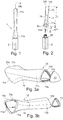
- the device 1 for packaging and application represented on the Figures 1 to 6 comprises a container 2 containing the eyeliner to be applied and an applicator 3, which, if not used to apply the product, can be mounted on the container 2 to close it, as illustrated in FIG. figure 1 , and separable from the container for applying the product, as illustrated in figure 2 .
- the applicator 3 extends along a rectilinear longitudinal axis X.
- the container 2 comprises for example a threaded neck on which can be screwed the applicator 3, the latter comprising a support 5 carrying an applicator member 6, consisting of an applicator tip.
- the applicator member 6 may be made in various ways, with a shape that allows the user to draw a more or less thick line depending on the orientation of the application. the applicator member 6 relative to the eyelid and the direction of movement thereon.
- the applicator member 6 may be formed by a felt tip or by a tip made of an elastomeric material, which may or may not be flocked at its distal end. Examples of suitable application members are described in particular in the publications FR 2 933 281 , FR 2 947 702 , FR 2,890,296 and US 7,077,592 .
- the applicator 3 comprises a handle 10 defining a gripping surface allowing the user to hold the applicator during the application of the product.
- the handle 10 comprises at least two transverse sections spaced apart from each other, generally of substantially triangular shape.
- the applicator thus has a first transverse section taken perpendicular to the longitudinal axis X of the applicator of generally triangular general shape, which is located closer to the distal end 10a of the handle, that is to say closer of the support 5 and the applicator member 6.
- the handle thus has three facets 11a arranged to define the first cross section of generally triangular general shape.
- the facets 11a are non-parallel to the longitudinal axis X of the applicator, being inclined at an angle ⁇ which is variable with respect to the axis X, as illustrated in FIG. figure 4a .
- Their inclination favors the support of the fingers on the facets and prevents them from sliding towards the support 5.
- the angle of inclination ⁇ can be of the order of 12 ° at the distal end of the handle 10.
- the container 2 has a shoulder 2a of substantially triangular shape also.
- the applicator has a second cross section taken perpendicularly to the longitudinal axis X of substantially triangular general shape, which is located closer to the proximal end of the applicator.
- the handle thus has three facets 11b arranged so as to define the cross section of generally triangular general shape.
- the facets 11a and 11b are each symmetrical with respect to a median plane containing the longitudinal axis X of the applicator.
- the six facets 11a and 11b of the handle 10 are arranged nested around the longitudinal axis X of the applicator.
- the bases of the three facets 11b are located on the side of the proximal end 10b of the handle, and the bases of the other three facets 11a are located on the side of the distal end 10a of the handle.
- the handle 10 further comprises a narrowed intermediate portion 14, located in the example described at about 1/3 L 1 of the proximal end and about 2/3 L 1 of the distal end, L 1 denoting the length of the handle.
- the handle thus has at least one intermediate cross section of shape other than substantially triangular, which is located along the longitudinal axis X of the applicator between the two cross sections of generally triangular general shape.
- the two cross sections of substantially triangular general shape are angularly offset relative to each other.
- the angular offset is 60 °, so that the vertices of the triangles of the two sections of substantially triangular general shape are staggered in a homogeneous and regular manner, as can be seen in the figures.
- the handle of the applicator according to the invention has a twisted appearance.
- the handle 10 houses a plug 13 at its proximal end 10b, visible more particularly on the Figures 3a, 3b and 6 . It is fixed to the handle 10 by snapping, by cooperation of an annular bead with a corresponding annular groove of the handle.
- L 2 being the apparent length of the support measured along the longitudinal axis X of the applicator, the ratio L 1 / L 2 is greater than 2, better than 3. This ratio may in particular be between 2 and 7, or even between 3 and 6.
- the apparent length L 2 is in the example described of the order of 20 mm.
- the length L 1 is in the example described of the order of 85 mm.
- the handle has a greater width l which is in the example described of the order of 15 mm. This larger width is here at the distal end 10a of the handle, the closest to the application member 6.
- the ratio L 1 / l of the length L 1 of the handle on its greatest width 1 is in the example described of the order of 5.
- the handle comprises snap-fastening reliefs 15 on its inner surface, intended for fixing the support 5 in the handle 10.
- the handle comprises three reliefs 15 each arranged at 120 ° one of the other, and near its distal end 10a, as illustrated.
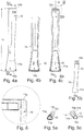
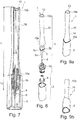
- the support 5 comprises a rod 5a which supports at its distal end the applicator member 6 and at its proximal end a fixing end 5b to the handle 10, as can be seen on the Figures 7 and 8 .
- This fixing end 5b ends with a triangular collar 5c.
- the container 2 houses a perforated open-ended sleeve 8, from which the applicator member 6 can be passed a short distance to be loaded with the product P contained in the container.
- a perforated open-ended sleeve 8 from which the applicator member 6 can be passed a short distance to be loaded with the product P contained in the container.
- the container can be given various shapes, for example an elongate shape of generally constant outer cross section, which is triangular in the embodiment of the invention.
- Figures 1 to 6 and in that of Figures 7 to 12 .
- the container is of a non-constant shape as one moves along the longitudinal axis X of the device.
- the cross section of the container is substantially triangular in shape at its connection to the handle, and circular to the bottom of the container.
- the container 2 is separated from the applicator 3 during the application of the product.
- the container 2 remains integral with the applicator member during the application of the product, the applicator member 6 being for example supplied with product by an internal channel from the container 2, the latter being able to be provided with a pump, or a free tank or with a soaked pad for a capillary supply, or any other system for forcing the product to flow through the aforementioned inner channel to reach the application surface.
- the applicator member 6 being for example supplied with product by an internal channel from the container 2, the latter being able to be provided with a pump, or a free tank or with a soaked pad for a capillary supply, or any other system for forcing the product to flow through the aforementioned inner channel to reach the application surface.
- the supply of the application surface can still be done through the porosity of the applicator member, by capillarity, through it.
- the applicator tip may be a felt, flocked or not, a sintered, a brush or a flocked tip.
- the applicator tip has a single, rounded tip.
- the applicator tip is "bi-trait", with two vertices making it possible to draw two lines simultaneously.
Description
- La présente invention concerne les applicateurs pour l'application d'un produit cosmétique, de maquillage ou de soin, notamment d'eyeliner ou de vernis à ongles ou de brillant à lèvres sur les paupières, les ongles, la peau, les lèvres par exemple, ainsi que les dispositifs de conditionnement et d'application notamment d'eyeliner.
- On connaît par le modèle d'utilité
DE 20 2011 104 712 U1 un stylo pour écrire ou appliquer un produit cosmétique, dont le manche est incurvé pour se conformer à la forme de la main, comportant une première surface de guidage pour supporter une surface intérieure de la main et une deuxième surface de guidage pour y passer un doigt. -
EP 2 342 991 A1 décrit un dispositif applicateur de produit cosmétique avec un corps avec une section transversale de forme triangulaire. - Le maquillage des paupières est une opération difficile à réaliser, qui consiste généralement à tracer un trait d'eyeliner en tenant la paupière étirée, en déplaçant l'organe d'application parallèlement à la paupière et à la frange de cils, d'un coin de la paupière à l'autre. Cette opération est relativement difficile à accomplir avec un pinceau compte-tenu de la petitesse de la surface à maquiller et de la précision nécessaire, et les crayons khôl sont préférentiellement utilisés par les consommateurs.
- Des applicateurs ont été proposés pour tenter de rendre cette opération plus facile, en essayant d'améliorer la tenue de l'organe d'application par l'utilisateur. Malgré la grande diversité des applicateurs qui ont pu être proposés, cette opération de maquillage reste délicate.
- Il existe par conséquent un besoin pour faciliter cette opération sans pour autant nuire à la qualité du maquillage réalisé.
- L'invention a ainsi pour objet, selon un premier de ses aspects, un applicateur pour appliquer un eyeliner tel que défini dans la revendication 1. :
L'applicateur selon l'invention est équipé d'un manche d'une longueur relativement importante par rapport au support. Ce manche a une longueur suffisante pour reposer par son partie distale sur la membrane inter-distale entre le pouce et l'index, ce qui peut permettre d'assurer un meilleur calage de celui-ci, et donc d'améliorer la précision de l'application. - En outre, le support est relativement court, ce qui peut faciliter le maquillage car les doigts qui reposent sur le manche sont situés plus près de l'organe d'application, ce qui permet un guidage plus précis de l'organe d'application.
- Le support peut s'étendre sur une longueur apparente L2 supérieure 7 mm, mieux supérieure à 9 mm, étant notamment comprise entre 7 et 25 mm, mieux entre 8 et 20 mm.
- Par « longueur apparente du support », on entend la longueur de la partie du support qui est visible lorsque l'applicateur dans son ensemble est observé de côté. La longueur apparente du support peut résulter de la différence entre la longueur totale de l'applicateur, à laquelle est soustraite la longueur du manche et celle de l'organe d'application.
- La longueur L1 est comprise de préférence entre 40 et 90 mm, mieux entre 50 et 80 mm.
- Le manche peut avoir une plus grande largeur l comprise entre 8 et 30 mm, mieux entre 10 et 20 mm. La plus grande largeur correspond à la plus grande dimension transversale mesurable sur toute la longueur du manche. Elle peut être donnée par exemple par le diamètre d'un cercle dans lequel est inscrite la section transversale du manche. Elle peut être située à l'extrémité proximale du manche, la plus proche de l'organe d'application..
- Le ratio L1/l de la longueur L1 du manche sur sa plus grande largeur l est de préférence compris entre 2 et 7, mieux entre 3 et 6.
- La forme sensiblement triangulaire de la section transversale favorise la prise du manche entre trois doigts d'une main par la pince tridigitale, entre le pouce, l'index et le majeur. Chaque doigt peut reposer sur une facette du manche sensiblement plane ou légèrement bombée, confortablement et de façon stable.
- Le manche peut présenter au moins deux sections transversales, distantes l'une de l'autre, de forme générale sensiblement triangulaire et au moins une section transversale médiane de forme autre que sensiblement triangulaire.
- De préférence, chaque section sensiblement triangulaire est sensiblement isocèle voire même équilatérale.
- L'applicateur peut présenter une première section transversale, prise perpendiculairement à l'axe longitudinal X de l'applicateur, de forme générale sensiblement triangulaire, située près de l'extrémité distale de l'applicateur, c'est-à-dire près du support et de l'organe d'application. La présence de cette section sensiblement triangulaire proche de l'organe d'application permet la préhension de l'applicateur entre trois doigts de la main, un côté reposant sur le majeur et les deux autres étant en contact l'un avec le pouce et l'autre avec l'index. Ainsi, l'applicateur est bien calé dans la main de l'utilisateur sans risque de rotation intempestive.
- En outre, l'applicateur peut présenter une deuxième section transversale de forme générale sensiblement triangulaire située près de l'extrémité proximale du manche. La présence à l'extrémité proximale du manche d'une section sensiblement triangulaire permet le positionnement satisfaisant de l'applicateur dans la main de l'utilisateur, car l'extrémité du manche peut reposer sur la membrane inter-distale entre le pouce et l'index. Le manche peut reposer sur cette membrane inter-distale soit par une facette, ce qui peut empêcher la rotation du manche dans la main, soit par une arête ménagée entre deux facettes du manche, ce qui peut permettre le calage du manche sur la main, par un certain effet d'enfoncement de cette arête dans le creux de la membrane. Le choix entre ces positions peut dépendre de l'utilisateur, dans la recherche d'un confort maximal à l'application.
- Les deux sections transversales de forme générale sensiblement triangulaire peuvent être décalées angulairement l'une par rapport à l'autre. Le décalage angulaire peut être compris entre 40 et 80°, étant par exemple de l'ordre de 60°, de manière à ce que les sommets des triangles des deux sections de forme générale sensiblement triangulaire soient décalés de manière homogène et régulière. Ainsi, le manche de l'applicateur selon l'invention peut présenter un aspect vrillé, compte tenu de ce décalage angulaire.
- Le manche peut présenter au moins trois facettes définissant la section transversale de forme générale sensiblement triangulaire, ces facettes étant non parallèles à l'axe longitudinal X de l'applicateur. Ces facettes peuvent être inclinées vers l'intérieur en éloignement de l'extrémité distale du manche, ce qui peut favoriser l'appui des doigts sur ces facettes éviter leur glissement en direction du support. Les facettes peuvent être chacune symétrique par rapport à un plan médian contenant l'axe longitudinal X de l'applicateur. Lorsque le manche est observé de côté, de façon sensiblement parallèle au côté défini par une facette, cette facette peut apparaître être incurvée et concave vers l'extérieur.
- Le manche présente au moins six facettes imbriquées tête-bêche autour de l'axe longitudinal X de l'applicateur. Les bases de trois des facettes peuvent être situées du côté de l'extrémité distale du manche, et les bases des trois autres facettes être situées du côté de l'extrémité proximale du manche.
- Le manche peut comporter une portion intermédiaire rétrécie. Cette portion peut être située à environ 1/3 L1 de l'extrémité distale et 2/3 L1 de l'extrémité proximale.
- L'invention a encore pour objet, indépendamment ou en combinaison avec ce qui précède, un applicateur pour appliquer un eyeliner, s'étendant selon un axe longitudinal X rectiligne, et comportant :
- un organe d'application, notamment une pointe applicatrice,
- un support portant l'organe d'application,
- un manche définissant une surface de préhension permettant à l'utilisateur de tenir l'applicateur lors de l'application du produit, le manche présentant au moins deux sections transversales distantes l'une de l'autre, chacune de forme générale sensiblement triangulaire, et au moins une section transversale intermédiaire de forme autre que sensiblement triangulaire.
- Les deux sections transversales de forme générale sensiblement triangulaire sont de préférence décalées angulairement l'une par rapport à l'autre, notamment de 60°. Les deux sections peuvent être de tailles différentes, la section à l'extrémité proximale du manche étant plus petite que celle à l'extrémité distale du manche. En outre, le manche peut comporter une portion intermédiaire rétrécie. Par ailleurs, l'applicateur peut comporter l'une ou l'autre des caractéristiques décrites précédemment, seules ou en combinaison.
- L'organe d'application peut être un embout floqué en élastomère, un pinceau, un feutre, un embout en mousse, une plume injectée, floquée ou non. Il est de préférence souple, comportant par exemple un corps en un élastomère thermoplastique. Dans le cas d'un feutre, il comporte de préférence des fibres orientées longitudinalement et liées entre elles. Le produit peut diffuser par capillarité au sein de l'organe d'application, du fait de sa porosité. Il peut s'agir de fibres en matière thermoplastique, notamment en polymère acrylique, en polyester ou polyamide. Les fibres peuvent être de titre inférieur à 1 denier, de préférence compris entre 0,5 et 0,9 deniers, notamment 0,7 deniers (soit 9 microns environ). Les fibres peuvent être en Nylon®.
- L'organe d'application peut présenter, sur au moins une partie de sa longueur, une section transversale non symétrique de révolution. Cela permet de réaliser un trait plus ou moins fin selon l'orientation de l'organe d'application par rapport à la direction de déplacement relativement à la paupière.
- Les dimensions de l'organe d'application sont telles que l'épaisseur maximale du trait de produit tracé sur la peau est de préférence inférieure ou égale à 5 mm, mieux inférieure ou égale à 3 mm, lorsque l'organe d'application est déplacé perpendiculairement à la peau. Selon l'orientation de l'organe d'application relativement à la paupière, on peut par exemple faire varier l'épaisseur du trait.
- L'organe d'application peut être fixé par tout moyen sur le support, par exemple inséré à force dans un logement correspondant prévu à l'extrémité du support.
- De préférence, l'organe d'application est une pointe applicatrice, étant munie ou non en extrémité d'une spatule ou d'une tête élargie comme décrit dans la demande
FR 2 933 281 - La pointe applicatrice peut comporter un embout de fixation au support de l'applicateur qui est de diamètre supérieur à la largeur du trait fin qui est tracé par l'applicateur lorsque celui-ci est déplacé en étant orienté perpendiculairement à la peau.
- Le manche peut être réalisé sous la forme d'un capot de fermeture d'un récipient. Le support ou le manche peut être agencé pour fermer, notamment de manière étanche, le récipient en l'absence d'utilisation.
- Le manche peut être réalisé dans un matériau unique, par exemple par moulage, ou avec un surmoulage d'un second matériau plus souple permettant de faciliter la préhension du manche.
- L'eyeliner peut comporter un solvant aqueux ou organique et un pigment, notamment un oxyde de fer. L'eyeliner contient par exemple de l'eau, un pigment, notamment de l'oxyde de fer et/ou un colorant, et des polymères.
- L'invention a encore pour objet un dispositif de conditionnement et d'application comportant un récipient contenant l'eye-liner à appliquer, et un applicateur selon l'invention, tel que défini ci-dessus.
- Le récipient peut comporter le cas échéant une bille permettant d'homogénéiser son contenu en secouant le récipient.
- La contenance du récipient est par exemple comprise entre 1 et 6 ml.
- L'organe d'application est alimenté en produit par trempage dans le récipient ou en variante l'alimentation de la surface d'application en produit se fait par capillarité à travers l'organe d'application, à l'instar des feutres d'écriture.
- Dans une telle variante de réalisation, le produit, notamment l'eyeliner, peut être contenu dans un réservoir disposé à l'intérieur du manche, l'applicateur formant ainsi un stylo applicateur d'eyeliner. Dans ce cas, l'organe d'application est de préférence intérieurement poreux, de forme allongée, étant alimenté en eyeliner par le réservoir. L'applicateur peut comporter un bouchon qui se fixe par exemple par encliquetage, vissage ou friction dans le manche de l'applicateur et qui sert au montage sur le col du récipient.
- Dans cet exemple, l'organe d'application est alimenté en produit par son extrémité proximale et le produit peut se diffuser longitudinalement dans l'organe d'application jusqu'à atteindre la portion destinée à venir en contact avec la peau. L'organe d'application présente dans ce cas une base qui sert à la fixation sur le support et une pointe qui sert à l'application, en venant au contact de la peau pour y déposer de l'eyeliner qui imprègne le feutre de l'organe d'application.
- L'invention a encore pour objet un procédé de maquillage de la paupière, dans lequel on utilise un applicateur ou un dispositif selon l'invention pour tracer un trait sur la paupière. On peut modifier au cours du maquillage l'orientation de l'organe d'application, notamment de la pointe applicatrice, relativement à la paupière et à la surface de préhension.
- L'utilisateur peut positionner le manche avec une orientation voulue relativement à la paupière, en fonction de l'épaisseur du trait à réaliser sur la paupière.
- L'invention pourra être mieux comprise à la lecture de la description détaillée qui va suivre, d'exemples de mise en oeuvre non limitatifs de celle-ci, et à l'examen du dessin annexé, sur lequel :
- les
figures 1 et 2 sont des vues en perspective, respectivement en positions fermée et ouverte, d'un exemple de dispositif de conditionnement et d'application conforme à l'invention, - les
figures 3a et 3b sont des vues en perspective du manche du dispositif desfigures 1 et 2 , - la
figure 4a est une vue de côté de ce même manche, - les
figures 4b et 4c sont des vues en coupe longitudinale dudit manche, respectivement selon IV B et IV C, - les
figures 5a à 5c sont d'autres vues en perspective du manche du dispositif desfigures 1 et 2 , - la
figure 6 est une vue du détail VI de lafigure 4c , - la
figure 7 est une vue en coupe longitudinale partielle d'une variante de réalisation, - la
figure 8 en est une vue en perspective, en éclaté, - les
figures 9a et 9b en sont des vues en perspective, - la
figure 10a est une vue de côté de ce même dispositif, - les
figures 10b et 10c sont des vues en coupe longitudinale respectivement selon X B et X C, - la
figure 11 en est une coupe transversale selon XI-XI, - la
figure 12 est une vue du détail XII de lafigure 10 , - les
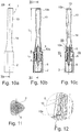
figures 13a à 13c sont des vues de côté d'une variante de réalisation, - la
figure 14 en est une vue en perspective, - la
figure 15 en est un vue de dessus selon XV de lafigure 13b , - la
figure 16 en est une coupe longitudinale selon XVI-XVI de lafigure 13a , - la
figure 17 est une vue du détail XVII de lafigure 16 , et - les
figures 18 et 19 sont des vues en perspective, en éclaté, de l'applicateur desfigures 13a à 17 . - Le dispositif 1 de conditionnement et d'application représenté sur les
figures 1 à 6 comporte un récipient 2 contenant l'eye-liner à appliquer et un applicateur 3, pouvant en l'absence d'utilisation pour appliquer le produit se monter sur le récipient 2 pour le fermer, comme illustré à lafigure 1 , et pouvant être séparé du récipient pour appliquer le produit, comme illustré à lafigure 2 . L'applicateur 3 s'étend selon un axe longitudinal X rectiligne. - Le récipient 2 comporte par exemple un col fileté sur lequel peut se visser l'applicateur 3, ce dernier comportant un support 5 portant un organe d'application 6, constitué par une pointe applicatrice.
- L'organe d'application 6 peut être réalisé de diverses façons, avec une forme qui permet à l'utilisateur de tracer un trait plus au moins épais selon l'orientation de l'organe d'application 6 par rapport à la paupière et la direction de déplacement sur celle-ci.
- L'organe d'application 6 peut être formé par un pointe feutre ou encore par un embout en un matériau élastomère, qui peut être ou non floqué à son extrémité distale. Des exemples d'organes d'application pouvant convenir sont décrits notamment dans les publications
FR 2 933 281 FR 2 947 702 FR 2 890 296 US 7 077 592 . - L'applicateur 3 comporte un manche 10 définissant une surface de préhension permettant à l'utilisateur de tenir l'applicateur lors de l'application du produit.
- Le manche 10 comporte au moins deux sections transversales distantes l'une de l'autre, de forme générale sensiblement triangulaire.
- L'applicateur comporte ainsi une première section transversale prise perpendiculairement à l'axe longitudinal X de l'applicateur de forme générale sensiblement triangulaire, laquelle est située plus près de l'extrémité distale 10a du manche, c'est-à-dire plus près du support 5 et de l'organe d'application 6. Le manche présente ainsi trois facettes 11a disposées de manière à définir la première section transversale de forme générale sensiblement triangulaire. Les facettes 11a sont non parallèles à l'axe longitudinal X de l'applicateur, étant inclinées d'un angle α variable par rapport à l'axe X, comme illustré sur la
figure 4a . Leur inclinaison favorise l'appui des doigts sur Les facettes et évite leur glissement en direction du support 5. L'angle d'inclinaison α peut être de l'ordre de 12° à l'extrémité distale du manche 10. - Le récipient 2 comporte un épaulement 2a de forme sensiblement triangulaire également.
- En outre, l'applicateur comporte une deuxième section transversale prise perpendiculairement à l'axe longitudinal X de forme générale sensiblement triangulaire, laquelle est située plus près de l'extrémité proximale de l'applicateur.
- Le manche présente ainsi trois facettes 11b disposées de manière à définir la section transversale de forme générale sensiblement triangulaire.
- Les facettes 11a et 11b sont chacune symétriques par rapport à un plan médian contenant l'axe longitudinal X de l'applicateur.
- Les six facettes 11a et 11b du manche 10 sont disposées imbriquées autour de l'axe longitudinal X de l'applicateur. Les bases des trois facettes 11b sont situées du côté de l'extrémité proximale 10b du manche, et les bases des trois autres facettes 11a sont situées du côté de l'extrémité distale 10a du manche.
- Le manche 10 comporte en outre une portion intermédiaire rétrécie 14, située dans l'exemple décrit à environ 1/3 L1 de l'extrémité proximale et à environ 2/3 L1 de l'extrémité distale, L1 désignant la longueur du manche. Le manche a ainsi au moins une section transversale intermédiaire de forme autre que sensiblement triangulaire, qui est située le long de l'axe longitudinal X de l'applicateur entre les deux sections transversales de forme générale sensiblement triangulaire.
- Les deux sections transversales de forme générale sensiblement triangulaire sont décalées angulairement l'une par rapport à l'autre. Le décalage angulaire est de 60°, de manière à ce que les sommets des triangles des deux sections de forme générale sensiblement triangulaire soient décalés de manière homogène et régulière, comme on peut le voir sur les figures. Ainsi, le manche de l'applicateur selon l'invention a un aspect vrillé.
- Le manche 10 loge un bouchon 13 à son extrémité proximale 10b, visible plus particulièrement sur les
figures 3a, 3b et6 . Il est fixé au manche 10 par encliquetage, par coopération d'un bourrelet annulaire avec une gorge annulaire correspondante du manche. - L2 étant la longueur apparente du support mesurée selon l'axe longitudinal X de l'applicateur, le ratio L1/L2 est supérieur à 2, mieux supérieur à 3. Ce ratio peut notamment être compris entre 2 et 7, voire entre 3 et 6.
- La longueur apparente L2 est dans l'exemple décrit de l'ordre de 20 mm. La longueur L1 est dans l'exemple décrit de l'ordre de 85 mm.
- Le manche a une plus grande largeur l qui est dans l'exemple décrit de l'ordre de 15 mm.. Cette plus grande largeur se situe ici à l'extrémité distale 10a du manche, la plus proche de l'organe d'application 6.
- Le ratio L1/l de la longueur L1 du manche sur sa plus grande largeur l est dans l'exemple décrit de l'ordre de 5.
- Le manche comporte des reliefs d'encliquetage 15 sur sa surface intérieure, destinés à la fixation du support 5 dans le manche 10. Dans l'exemple de réalisation décrit, le manche comporte trois reliefs 15 disposés chacun à 120° l'un de l'autre, et à proximité de son extrémité distale 10a, comme illustré.
- Les structures du support, de l'organe d'application et du récipient seront décrites plus en détails en lien avec le mode de réalisation des
figures 7 à 12 , mais peuvent bien entendu être identiques pour le mode de réalisation desfigures 1 à 6 . - Le support 5 comporte une tige 5a qui supporte à son extrémité distale l'organe d'application 6 et à son extrémité proximale un embout de fixation 5b au manche 10, comme on peut le voir sur les
figures 7 et 8 . Cet embout de fixation 5b se termine par une collerette triangulaire 5c. - Le récipient 2 loge une gaine ajourée 8 ouverte en bout, de laquelle peut dépasser l'organe d'application 6 d'une faible distance pour se charger avec le produit P contenu dans le récipient. Un exemple d'un tel agencement est divulgué notamment dans la publication
FR 2 947 702 - On peut donner au récipient diverses formes, par exemple une forme allongée de section transversale extérieure généralement constante, qui est triangulaire dans le mode de réalisation des
figures 1 à 6 , et dans celui desfigures 7 à 12 . - Dans le mode de réalisation des
figures 13a à 19 , le récipient est d'une forme non constante lorsque l'on se déplace le long de l'axe longitudinal X du dispositif. La section transversale du récipient est de forme sensiblement triangulaire au niveau de son raccordement au manche, et de forme circulaire vers le fond du récipient. - Dans les exemples de réalisation qui viennent d'être décrits, le récipient 2 est séparé de l'applicateur 3 lors de l'application du produit.
- En variante, le récipient 2 reste solidaire de l'organe d'application durant l'application du produit, l'organe d'application 6 étant par exemple alimenté en produit par un canal intérieur depuis le récipient 2, ce dernier pouvant être muni d'une pompe, ou encore d'un réservoir libre ou comportant un tampon imbibé permettant une alimentation par capillarité, ou de tout autre système permettant de forcer le produit à s'écouler par le canal intérieur précité pour atteindre la surface d'application.
- L'alimentation de la surface d'application peut encore se faire grâce à la porosité de l'organe d'application, par capillarité, à travers celui-ci.
- Bien entendu, l'invention n'est pas limitée aux exemples qui viennent d'être décrits.
- En particulier, on peut combiner les caractéristiques des divers exemples illustrés au sein de variantes non illustrées, en particulier tant qu'ils tombent dans l'étendu de la protection, tel que défini dans les revendications. La pointe d'applicatrice peut être un feutre, floqué ou non, un fritté, un pinceau ou un embout floqué. De préférence, la pointe applicatrice a un unique sommet, arrondi. Dans une variante, la pointe d'applicatrice est « bi-trait », avec deux sommets permettant de tracer deux traits simultanément.
- L'expression « comportant un » doit être comprise comme étant synonyme de « comprenant au moins un », sauf si le contraire est spécifié.
Claims (11)
- Applicateur (3) pour appliquer un eyeliner, s'étendant selon un axe longitudinal (X) rectiligne, et comportant :- un organe d'application (6), notamment une pointe applicatrice,- un support (5) portant l'organe d'application (6), s'étendant sur une longueur apparente (L2) mesurée selon l'axe longitudinal (X) de l'applicateur,- un manche (10) définissant une surface de préhension permettant à l'utilisateur de tenir l'applicateur lors de l'application du produit, le manche (10) présentant au moins une section transversale, prise perpendiculairement à l'axe longitudinal (X) de l'applicateur, de forme générale sensiblement triangulaire, et le manche s'étendant sur une longueur (L1) mesurée selon l'axe longitudinal (X) de l'applicateur,le ratio L1/L2 de la longueur du manche (L1) sur la longueur apparente du support (L2) étant supérieur à 2, le manche (10) présentant au moins deux sections transversales distantes l'une de l'autre, de forme générale sensiblement triangulaire, les deux sections transversales de forme générale sensiblement triangulaire étant décalées angulairement l'une par rapport à l'autre.
- Applicateur selon l'une quelconque des revendications précédentes, le support (5) s'étendant sur une longueur apparente (L2) supérieure à 7 mm, mieux supérieure à 9 mm.
- Applicateur selon l'une des revendications précédentes, le manche (10) s'étendant sur une longueur (L1) comprise entre 40 et 90 mm, mieux entre 50 et 80 mm.
- Applicateur selon l'une quelconque des revendications précédentes, dans lequel le manche (10) a une plus grande largeur (l) comprise entre 8 et 30 mm, mieux entre 10 et 20 mm.
- Applicateur selon l'une quelconque des revendications précédentes, le ratio L1/l de la longueur (L1) du manche (10) sur sa plus grande largeur (l) étant compris entre 2 et 7, mieux entre 3 et 6.
- Applicateur selon l'une quelconque des revendications précédentes, le manche (10) présentant au moins une section transversale intermédiaire de forme autre que sensiblement triangulaire.
- Applicateur selon l'une quelconque des revendications précédentes, le manche (10) présentant au moins trois facettes (11a, 11b) disposées de manière à définir la section transversale de forme générale sensiblement triangulaire, lesdites facettes étant non parallèles à l'axe longitudinal (X) de l'applicateur.
- Applicateur selon l'une quelconque des revendications précédentes, le manche (10) présentant au moins six facettes (11a, 11b) imbriquées tête-bêche autour de l'axe longitudinal (X) de l'applicateur.
- Applicateur selon l'une quelconque des revendications précédentes, le manche (10) présentant une portion intermédiaire rétrécie (14).
- Dispositif (1) de conditionnement et d'application comportant un récipient (2) contenant un eye-liner à appliquer et un applicateur (3) selon l'une quelconque des revendications précédentes.
- Procédé de maquillage de la paupière, dans lequel on utilise un applicateur (3) ou un dispositif (1) selon l'une quelconque des revendications précédentes pour tracer un trait sur la paupière.
Applications Claiming Priority (2)
| Application Number | Priority Date | Filing Date | Title |
|---|---|---|---|
| FR1461290A FR3028727B1 (fr) | 2014-11-21 | 2014-11-21 | Applicateur pour appliquer un produit cosmetique de maquillage ou de soin |
| PCT/EP2015/077275 WO2016079325A1 (fr) | 2014-11-21 | 2015-11-20 | Applicateur pour appliquer un produit cosmetique, de maquillage ou de soin |
Publications (2)
| Publication Number | Publication Date |
|---|---|
| EP3221231A1 EP3221231A1 (fr) | 2017-09-27 |
| EP3221231B1 true EP3221231B1 (fr) | 2018-08-15 |
Family
ID=52273341
Family Applications (1)
| Application Number | Title | Priority Date | Filing Date |
|---|---|---|---|
| EP15798095.4A Active EP3221231B1 (fr) | 2014-11-21 | 2015-11-20 | Applicateur pour appliquer un produit cosmetique, de maquillage ou de soin |
Country Status (8)
| Country | Link |
|---|---|
| US (1) | US10499720B2 (fr) |
| EP (1) | EP3221231B1 (fr) |
| JP (1) | JP6346996B2 (fr) |
| KR (1) | KR101828761B1 (fr) |
| CN (1) | CN106937528B (fr) |
| ES (1) | ES2693350T3 (fr) |
| FR (1) | FR3028727B1 (fr) |
| WO (1) | WO2016079325A1 (fr) |
Families Citing this family (4)
| Publication number | Priority date | Publication date | Assignee | Title |
|---|---|---|---|---|
| US20180169852A1 (en) * | 2015-03-23 | 2018-06-21 | Nextgen Knives, Llc | Customizable And Ergonomic Handle |
| JP1653919S (fr) * | 2019-07-10 | 2020-03-02 | ||
| EP4312657A1 (fr) | 2021-03-29 | 2024-02-07 | L'oreal | Appareil de stockage et d'application d'un produit |
| FR3122070A1 (fr) | 2021-04-26 | 2022-10-28 | L'oreal | Appareil pour stocker et appliquer un produit |
Family Cites Families (38)
| Publication number | Priority date | Publication date | Assignee | Title |
|---|---|---|---|---|
| US4313686A (en) * | 1980-02-04 | 1982-02-02 | Proffer Charles L | Container cap with neck abutting retractable applicator |
| EP0375856A3 (fr) * | 1988-10-21 | 1991-11-06 | Ikeda Industry Corporation | Applicateur pour maquillage des yeux |
| JP2517761B2 (ja) * | 1989-06-07 | 1996-07-24 | 百能工業股▲ひん▼有限公司 | 筆記具 |
| JP3063585B2 (ja) | 1995-09-05 | 2000-07-12 | 株式会社トキワ | 液状化粧料塗布容器 |
| US5775344A (en) * | 1996-02-09 | 1998-07-07 | Clay; Mary A. | Cosmetic container and applicator with heating apparatus |
| US6039053A (en) * | 1999-03-10 | 2000-03-21 | Turrentine; Mary Faye | Cosmetic applicator |
| WO2002051284A2 (fr) * | 2000-12-26 | 2002-07-04 | Avon Products, Inc. | Brosses a applicateur et procede d'utilisation |
| US7077592B2 (en) | 2002-02-19 | 2006-07-18 | L'oreal S.A. | Applicator including an applicator element configured to apply substance to skin |
| US20040195377A1 (en) * | 2002-09-25 | 2004-10-07 | Shannon Walker Williams | Nail polish applicator |
| US7399134B2 (en) * | 2003-02-07 | 2008-07-15 | L'oreal | Packaging and applicator device |
| FR2851435B1 (fr) | 2003-02-24 | 2006-07-14 | Oreal | Dispositif de conditionnement et d'application d'un produit cosmetique. |
| FR2854779B1 (fr) | 2003-05-14 | 2006-09-01 | Oreal | Applicateur et dispositif de conditionnement et d'application comportant un tel applicateur |
| JP3098191U (ja) | 2003-05-29 | 2004-02-19 | 奥村 実 | 筆記具用グリップ及びそのセット |
| US20050126584A1 (en) * | 2003-12-11 | 2005-06-16 | Kuo-Sung Hsu | Container for a beauty product |
| JP2006021430A (ja) | 2004-07-08 | 2006-01-26 | Kotobuki & Co Ltd | 筆記具のクリップ付きノック部材の回り止め構造 |
| FR2882234B1 (fr) * | 2005-02-18 | 2007-11-16 | Oreal | Applicateur et dispositif de conditionnement et d'application. |
| FR2882506B1 (fr) * | 2005-02-25 | 2007-05-18 | Oreal | Procede de maquillage au moyen d'un applicateur vibrant |
| FR2890296B1 (fr) | 2005-09-06 | 2007-11-16 | Oreal | Dispositif de conditionnement et d'application d'un eye-liner liquide. |
| JP5069931B2 (ja) * | 2007-04-03 | 2012-11-07 | 株式会社壽 | 棒状物繰り出し容器 |
| US8985883B2 (en) * | 2007-07-30 | 2015-03-24 | The Procter & Gamble Company | Control surfaces for applicator with moveable applicator head |
| JP5223142B2 (ja) | 2008-04-21 | 2013-06-26 | 有限会社ユイット | 塗布用固形材料供給容器 |
| FR2933281B1 (fr) * | 2008-07-02 | 2011-12-30 | Oreal | Applicateur d'eyeliner |
| FR2933854B1 (fr) | 2008-07-16 | 2011-08-26 | Oreal | Applicateur pour peigner ou appliquer un produit sur les cils ou les sourcils. |
| FR2947702B1 (fr) * | 2009-07-09 | 2011-08-26 | Oreal | Dispositif comportant un applicateur d'eyeliner |
| FR2955019B1 (fr) * | 2010-01-12 | 2012-04-27 | Oreal | Dispositif applicateur de produit cosmetique, et ensemble comprenant un tel dispositif |
| US20120048290A1 (en) * | 2010-08-24 | 2012-03-01 | Frank Anthony Cappello | Dispensing apparatus |
| DE202010013587U1 (de) * | 2010-09-24 | 2012-01-09 | Geka Gmbh | Kosmetikapplikator mit einem Auftragselement |
| KR101502714B1 (ko) * | 2010-12-29 | 2015-03-13 | 이엘씨 매니지먼트 엘엘씨 | 열에 의해 열화될 수 있는 제품을 위한 가열식 도포기 시스템 |
| DE202011104712U1 (de) | 2011-08-18 | 2012-11-20 | Schwan-Stabilo Cosmetics Gmbh & Co. Kg | Auftraggerät |
| USD681469S1 (en) * | 2012-05-29 | 2013-05-07 | Better Look International LLC | Nail polish bottle with applicator cap |
| US9301592B2 (en) * | 2012-08-06 | 2016-04-05 | M.Y.H Ltd | Multi-purpose makeup applicator |
| ITTO20130035U1 (it) * | 2013-03-07 | 2014-09-08 | Baralan Internat S P A | Flacone per il contenimento di prodotti spalmabili |
| USD732975S1 (en) * | 2013-04-03 | 2015-06-30 | Jian Hua | Pyramid child-proof bottle |
| FR3006565B1 (fr) | 2013-06-06 | 2017-02-24 | Oreal | Applicateur pour appliquer un produit sur les cils et/ou les sourcils |
| US10477956B2 (en) * | 2013-08-20 | 2019-11-19 | HCT Group Holdings Limited | Cosmetic systems |
| US9185960B2 (en) * | 2013-11-08 | 2015-11-17 | Julep Beauty, Inc. | Stylus for cosmetics, nail polish applicator and systems and kits based thereon |
| US20150157111A1 (en) * | 2013-12-05 | 2015-06-11 | Aisha Smith-Thompson | Make-up apparatus |
| US20160374457A1 (en) * | 2015-06-25 | 2016-12-29 | Tight Line Cosmetics, Inc. | Cosmetic container identifier system |
-
2014
- 2014-11-21 FR FR1461290A patent/FR3028727B1/fr not_active Expired - Fee Related
-
2015
- 2015-11-20 US US15/528,721 patent/US10499720B2/en active Active
- 2015-11-20 JP JP2017527243A patent/JP6346996B2/ja not_active Expired - Fee Related
- 2015-11-20 WO PCT/EP2015/077275 patent/WO2016079325A1/fr active Application Filing
- 2015-11-20 KR KR1020177015448A patent/KR101828761B1/ko active IP Right Grant
- 2015-11-20 ES ES15798095.4T patent/ES2693350T3/es active Active
- 2015-11-20 EP EP15798095.4A patent/EP3221231B1/fr active Active
- 2015-11-20 CN CN201580063149.7A patent/CN106937528B/zh not_active Expired - Fee Related
Non-Patent Citations (1)
| Title |
|---|
| None * |
Also Published As
| Publication number | Publication date |
|---|---|
| KR101828761B1 (ko) | 2018-02-12 |
| JP2017535348A (ja) | 2017-11-30 |
| ES2693350T3 (es) | 2018-12-11 |
| CN106937528B (zh) | 2018-12-28 |
| WO2016079325A1 (fr) | 2016-05-26 |
| KR20170077242A (ko) | 2017-07-05 |
| CN106937528A (zh) | 2017-07-07 |
| FR3028727A1 (fr) | 2016-05-27 |
| JP6346996B2 (ja) | 2018-06-20 |
| US20170273436A1 (en) | 2017-09-28 |
| US10499720B2 (en) | 2019-12-10 |
| EP3221231A1 (fr) | 2017-09-27 |
| FR3028727B1 (fr) | 2018-01-26 |
Similar Documents
| Publication | Publication Date | Title |
|---|---|---|
| EP1726235B1 (fr) | Dispositif de conditionnement et d'application | |
| EP1504691B1 (fr) | Applicateur et dispositif de conditionnement et d'application comportant un tel applicateur. | |
| EP1745717B1 (fr) | Dispositif de conditionnement et d'application d'un produit | |
| FR3026620A1 (fr) | Applicateur pour l'application d'un produit cosmetique | |
| EP2978339B1 (fr) | Applicateur de produit cosmétique avec organe de massage | |
| EP3221231B1 (fr) | Applicateur pour appliquer un produit cosmetique, de maquillage ou de soin | |
| EP3420845B1 (fr) | Embout applicateur pour produit cosmétique, applicateur et ensemble applicateur associés | |
| FR3092232A1 (fr) | Applicateur de cosmetique | |
| FR2933281A1 (fr) | Applicateur d'eyeliner | |
| EP3302167B1 (fr) | Applicateur cosmetique | |
| EP3310208B1 (fr) | Applicateur cosmétique | |
| FR3043531A1 (fr) | Applicateur pour l'application d'un produit cosmetique | |
| FR3012946A1 (fr) | Stylo applicateur d'eyeliner | |
| EP2938223B1 (fr) | Systeme de conditionnement et d'application d'une composition cosmetique et son utilisation | |
| FR3027778A1 (fr) | Applicateur pour appliquer un produit cosmetique ou de soin | |
| EP1733644A1 (fr) | Pinceau et dispositif de conditionnement et d'application comportant un tel pinceau | |
| FR3066682A1 (fr) | Applicateur en forme de cuillere | |
| FR2976166A1 (fr) | Applicateur d'eye-liner | |
| FR3029089A1 (fr) | Dispositif de conditionnement et d'application d'eyeliner | |
| EP1369055A2 (fr) | Applicateur comportant une tige reliée par une articulation à un organe de préhension | |
| FR3111773A1 (fr) | Applicateur cosmétique à cavité supportée par des branches support | |
| FR2898471A1 (fr) | Dispositif de conditionnement et d'application | |
| FR3036599A1 (fr) | Applicateur de produit cosmetique ou de soin | |
| FR3058621A1 (fr) | Element d’application comprenant des cavites concaves paralleles | |
| FR2952511A1 (fr) | Tete applicatrice comportant un element d'application poreux. |
Legal Events
| Date | Code | Title | Description |
|---|---|---|---|
| STAA | Information on the status of an ep patent application or granted ep patent |
Free format text: STATUS: THE INTERNATIONAL PUBLICATION HAS BEEN MADE |
|
| PUAI | Public reference made under article 153(3) epc to a published international application that has entered the european phase |
Free format text: ORIGINAL CODE: 0009012 |
|
| STAA | Information on the status of an ep patent application or granted ep patent |
Free format text: STATUS: REQUEST FOR EXAMINATION WAS MADE |
|
| 17P | Request for examination filed |
Effective date: 20170509 |
|
| AK | Designated contracting states |
Kind code of ref document: A1 Designated state(s): AL AT BE BG CH CY CZ DE DK EE ES FI FR GB GR HR HU IE IS IT LI LT LU LV MC MK MT NL NO PL PT RO RS SE SI SK SM TR |
|
| AX | Request for extension of the european patent |
Extension state: BA ME |
|
| DAV | Request for validation of the european patent (deleted) | ||
| DAX | Request for extension of the european patent (deleted) | ||
| GRAP | Despatch of communication of intention to grant a patent |
Free format text: ORIGINAL CODE: EPIDOSNIGR1 |
|
| STAA | Information on the status of an ep patent application or granted ep patent |
Free format text: STATUS: GRANT OF PATENT IS INTENDED |
|
| INTG | Intention to grant announced |
Effective date: 20180430 |
|
| GRAS | Grant fee paid |
Free format text: ORIGINAL CODE: EPIDOSNIGR3 |
|
| GRAA | (expected) grant |
Free format text: ORIGINAL CODE: 0009210 |
|
| STAA | Information on the status of an ep patent application or granted ep patent |
Free format text: STATUS: THE PATENT HAS BEEN GRANTED |
|
| AK | Designated contracting states |
Kind code of ref document: B1 Designated state(s): AL AT BE BG CH CY CZ DE DK EE ES FI FR GB GR HR HU IE IS IT LI LT LU LV MC MK MT NL NO PL PT RO RS SE SI SK SM TR |
|
| REG | Reference to a national code |
Ref country code: CH Ref legal event code: EP Ref country code: GB Ref legal event code: FG4D Free format text: NOT ENGLISH Ref country code: AT Ref legal event code: REF Ref document number: 1029474 Country of ref document: AT Kind code of ref document: T Effective date: 20180815 |
|
| REG | Reference to a national code |
Ref country code: IE Ref legal event code: FG4D Free format text: LANGUAGE OF EP DOCUMENT: FRENCH |
|
| REG | Reference to a national code |
Ref country code: DE Ref legal event code: R096 Ref document number: 602015014935 Country of ref document: DE |
|
| REG | Reference to a national code |
Ref country code: FR Ref legal event code: PLFP Year of fee payment: 4 |
|
| REG | Reference to a national code |
Ref country code: ES Ref legal event code: FG2A Ref document number: 2693350 Country of ref document: ES Kind code of ref document: T3 Effective date: 20181211 |
|
| REG | Reference to a national code |
Ref country code: NL Ref legal event code: MP Effective date: 20180815 |
|
| REG | Reference to a national code |
Ref country code: LT Ref legal event code: MG4D |
|
| REG | Reference to a national code |
Ref country code: AT Ref legal event code: MK05 Ref document number: 1029474 Country of ref document: AT Kind code of ref document: T Effective date: 20180815 |
|
| PG25 | Lapsed in a contracting state [announced via postgrant information from national office to epo] |
Ref country code: NO Free format text: LAPSE BECAUSE OF FAILURE TO SUBMIT A TRANSLATION OF THE DESCRIPTION OR TO PAY THE FEE WITHIN THE PRESCRIBED TIME-LIMIT Effective date: 20181115 Ref country code: NL Free format text: LAPSE BECAUSE OF FAILURE TO SUBMIT A TRANSLATION OF THE DESCRIPTION OR TO PAY THE FEE WITHIN THE PRESCRIBED TIME-LIMIT Effective date: 20180815 Ref country code: BG Free format text: LAPSE BECAUSE OF FAILURE TO SUBMIT A TRANSLATION OF THE DESCRIPTION OR TO PAY THE FEE WITHIN THE PRESCRIBED TIME-LIMIT Effective date: 20181115 Ref country code: LT Free format text: LAPSE BECAUSE OF FAILURE TO SUBMIT A TRANSLATION OF THE DESCRIPTION OR TO PAY THE FEE WITHIN THE PRESCRIBED TIME-LIMIT Effective date: 20180815 Ref country code: IS Free format text: LAPSE BECAUSE OF FAILURE TO SUBMIT A TRANSLATION OF THE DESCRIPTION OR TO PAY THE FEE WITHIN THE PRESCRIBED TIME-LIMIT Effective date: 20181215 Ref country code: RS Free format text: LAPSE BECAUSE OF FAILURE TO SUBMIT A TRANSLATION OF THE DESCRIPTION OR TO PAY THE FEE WITHIN THE PRESCRIBED TIME-LIMIT Effective date: 20180815 Ref country code: AT Free format text: LAPSE BECAUSE OF FAILURE TO SUBMIT A TRANSLATION OF THE DESCRIPTION OR TO PAY THE FEE WITHIN THE PRESCRIBED TIME-LIMIT Effective date: 20180815 Ref country code: GR Free format text: LAPSE BECAUSE OF FAILURE TO SUBMIT A TRANSLATION OF THE DESCRIPTION OR TO PAY THE FEE WITHIN THE PRESCRIBED TIME-LIMIT Effective date: 20181116 Ref country code: FI Free format text: LAPSE BECAUSE OF FAILURE TO SUBMIT A TRANSLATION OF THE DESCRIPTION OR TO PAY THE FEE WITHIN THE PRESCRIBED TIME-LIMIT Effective date: 20180815 Ref country code: SE Free format text: LAPSE BECAUSE OF FAILURE TO SUBMIT A TRANSLATION OF THE DESCRIPTION OR TO PAY THE FEE WITHIN THE PRESCRIBED TIME-LIMIT Effective date: 20180815 |
|
| PG25 | Lapsed in a contracting state [announced via postgrant information from national office to epo] |
Ref country code: AL Free format text: LAPSE BECAUSE OF FAILURE TO SUBMIT A TRANSLATION OF THE DESCRIPTION OR TO PAY THE FEE WITHIN THE PRESCRIBED TIME-LIMIT Effective date: 20180815 Ref country code: LV Free format text: LAPSE BECAUSE OF FAILURE TO SUBMIT A TRANSLATION OF THE DESCRIPTION OR TO PAY THE FEE WITHIN THE PRESCRIBED TIME-LIMIT Effective date: 20180815 Ref country code: HR Free format text: LAPSE BECAUSE OF FAILURE TO SUBMIT A TRANSLATION OF THE DESCRIPTION OR TO PAY THE FEE WITHIN THE PRESCRIBED TIME-LIMIT Effective date: 20180815 |
|
| PG25 | Lapsed in a contracting state [announced via postgrant information from national office to epo] |
Ref country code: PL Free format text: LAPSE BECAUSE OF FAILURE TO SUBMIT A TRANSLATION OF THE DESCRIPTION OR TO PAY THE FEE WITHIN THE PRESCRIBED TIME-LIMIT Effective date: 20180815 Ref country code: EE Free format text: LAPSE BECAUSE OF FAILURE TO SUBMIT A TRANSLATION OF THE DESCRIPTION OR TO PAY THE FEE WITHIN THE PRESCRIBED TIME-LIMIT Effective date: 20180815 Ref country code: CZ Free format text: LAPSE BECAUSE OF FAILURE TO SUBMIT A TRANSLATION OF THE DESCRIPTION OR TO PAY THE FEE WITHIN THE PRESCRIBED TIME-LIMIT Effective date: 20180815 Ref country code: RO Free format text: LAPSE BECAUSE OF FAILURE TO SUBMIT A TRANSLATION OF THE DESCRIPTION OR TO PAY THE FEE WITHIN THE PRESCRIBED TIME-LIMIT Effective date: 20180815 |
|
| REG | Reference to a national code |
Ref country code: DE Ref legal event code: R097 Ref document number: 602015014935 Country of ref document: DE |
|
| PG25 | Lapsed in a contracting state [announced via postgrant information from national office to epo] |
Ref country code: SM Free format text: LAPSE BECAUSE OF FAILURE TO SUBMIT A TRANSLATION OF THE DESCRIPTION OR TO PAY THE FEE WITHIN THE PRESCRIBED TIME-LIMIT Effective date: 20180815 Ref country code: DK Free format text: LAPSE BECAUSE OF FAILURE TO SUBMIT A TRANSLATION OF THE DESCRIPTION OR TO PAY THE FEE WITHIN THE PRESCRIBED TIME-LIMIT Effective date: 20180815 Ref country code: SK Free format text: LAPSE BECAUSE OF FAILURE TO SUBMIT A TRANSLATION OF THE DESCRIPTION OR TO PAY THE FEE WITHIN THE PRESCRIBED TIME-LIMIT Effective date: 20180815 |
|
| PLBE | No opposition filed within time limit |
Free format text: ORIGINAL CODE: 0009261 |
|
| STAA | Information on the status of an ep patent application or granted ep patent |
Free format text: STATUS: NO OPPOSITION FILED WITHIN TIME LIMIT |
|
| REG | Reference to a national code |
Ref country code: CH Ref legal event code: PL |
|
| 26N | No opposition filed |
Effective date: 20190516 |
|
| PG25 | Lapsed in a contracting state [announced via postgrant information from national office to epo] |
Ref country code: MC Free format text: LAPSE BECAUSE OF FAILURE TO SUBMIT A TRANSLATION OF THE DESCRIPTION OR TO PAY THE FEE WITHIN THE PRESCRIBED TIME-LIMIT Effective date: 20180815 Ref country code: LU Free format text: LAPSE BECAUSE OF NON-PAYMENT OF DUE FEES Effective date: 20181120 |
|
| REG | Reference to a national code |
Ref country code: BE Ref legal event code: MM Effective date: 20181130 |
|
| REG | Reference to a national code |
Ref country code: IE Ref legal event code: MM4A |
|
| PG25 | Lapsed in a contracting state [announced via postgrant information from national office to epo] |
Ref country code: LI Free format text: LAPSE BECAUSE OF NON-PAYMENT OF DUE FEES Effective date: 20181130 Ref country code: CH Free format text: LAPSE BECAUSE OF NON-PAYMENT OF DUE FEES Effective date: 20181130 Ref country code: SI Free format text: LAPSE BECAUSE OF FAILURE TO SUBMIT A TRANSLATION OF THE DESCRIPTION OR TO PAY THE FEE WITHIN THE PRESCRIBED TIME-LIMIT Effective date: 20180815 |
|
| PG25 | Lapsed in a contracting state [announced via postgrant information from national office to epo] |
Ref country code: IE Free format text: LAPSE BECAUSE OF NON-PAYMENT OF DUE FEES Effective date: 20181120 |
|
| PG25 | Lapsed in a contracting state [announced via postgrant information from national office to epo] |
Ref country code: BE Free format text: LAPSE BECAUSE OF NON-PAYMENT OF DUE FEES Effective date: 20181130 |
|
| PG25 | Lapsed in a contracting state [announced via postgrant information from national office to epo] |
Ref country code: MT Free format text: LAPSE BECAUSE OF FAILURE TO SUBMIT A TRANSLATION OF THE DESCRIPTION OR TO PAY THE FEE WITHIN THE PRESCRIBED TIME-LIMIT Effective date: 20180815 |
|
| PG25 | Lapsed in a contracting state [announced via postgrant information from national office to epo] |
Ref country code: TR Free format text: LAPSE BECAUSE OF FAILURE TO SUBMIT A TRANSLATION OF THE DESCRIPTION OR TO PAY THE FEE WITHIN THE PRESCRIBED TIME-LIMIT Effective date: 20180815 |
|
| PG25 | Lapsed in a contracting state [announced via postgrant information from national office to epo] |
Ref country code: PT Free format text: LAPSE BECAUSE OF FAILURE TO SUBMIT A TRANSLATION OF THE DESCRIPTION OR TO PAY THE FEE WITHIN THE PRESCRIBED TIME-LIMIT Effective date: 20180815 |
|
| PG25 | Lapsed in a contracting state [announced via postgrant information from national office to epo] |
Ref country code: MK Free format text: LAPSE BECAUSE OF NON-PAYMENT OF DUE FEES Effective date: 20180815 Ref country code: CY Free format text: LAPSE BECAUSE OF FAILURE TO SUBMIT A TRANSLATION OF THE DESCRIPTION OR TO PAY THE FEE WITHIN THE PRESCRIBED TIME-LIMIT Effective date: 20180815 Ref country code: HU Free format text: LAPSE BECAUSE OF FAILURE TO SUBMIT A TRANSLATION OF THE DESCRIPTION OR TO PAY THE FEE WITHIN THE PRESCRIBED TIME-LIMIT; INVALID AB INITIO Effective date: 20151120 |
|
| PGFP | Annual fee paid to national office [announced via postgrant information from national office to epo] |
Ref country code: GB Payment date: 20230928 Year of fee payment: 9 |
|
| PGFP | Annual fee paid to national office [announced via postgrant information from national office to epo] |
Ref country code: FR Payment date: 20230929 Year of fee payment: 9 |
|
| PGFP | Annual fee paid to national office [announced via postgrant information from national office to epo] |
Ref country code: ES Payment date: 20231207 Year of fee payment: 9 |
|
| PGFP | Annual fee paid to national office [announced via postgrant information from national office to epo] |
Ref country code: IT Payment date: 20231010 Year of fee payment: 9 Ref country code: DE Payment date: 20230926 Year of fee payment: 9 |