EP3221221B2 - Dispositif de contrôle optique d'une face d'une découpe, machine de traitement de découpes et plieuse-colleuse comprenant le dispositif. - Google Patents
Dispositif de contrôle optique d'une face d'une découpe, machine de traitement de découpes et plieuse-colleuse comprenant le dispositif. Download PDFInfo
- Publication number
- EP3221221B2 EP3221221B2 EP15797861.0A EP15797861A EP3221221B2 EP 3221221 B2 EP3221221 B2 EP 3221221B2 EP 15797861 A EP15797861 A EP 15797861A EP 3221221 B2 EP3221221 B2 EP 3221221B2
- Authority
- EP
- European Patent Office
- Prior art keywords
- box
- suction section
- suction
- downstream
- upstream
- Prior art date
- Legal status (The legal status is an assumption and is not a legal conclusion. Google has not performed a legal analysis and makes no representation as to the accuracy of the status listed.)
- Active
Links
- 238000011144 upstream manufacturing Methods 0.000 claims description 28
- 238000007689 inspection Methods 0.000 claims description 27
- 230000003287 optical effect Effects 0.000 claims description 4
- 230000007547 defect Effects 0.000 description 4
- 238000004519 manufacturing process Methods 0.000 description 4
- 238000004026 adhesive bonding Methods 0.000 description 3
- 238000004049 embossing Methods 0.000 description 3
- 238000004806 packaging method and process Methods 0.000 description 3
- 238000005520 cutting process Methods 0.000 description 2
- 230000000717 retained effect Effects 0.000 description 2
- 239000003086 colorant Substances 0.000 description 1
- 238000009826 distribution Methods 0.000 description 1
- 238000000034 method Methods 0.000 description 1
- 238000012986 modification Methods 0.000 description 1
- 230000004048 modification Effects 0.000 description 1
- 239000000123 paper Substances 0.000 description 1
- 238000003825 pressing Methods 0.000 description 1
- 238000003908 quality control method Methods 0.000 description 1
- 238000011179 visual inspection Methods 0.000 description 1
Images
Classifications
-
- B—PERFORMING OPERATIONS; TRANSPORTING
- B65—CONVEYING; PACKING; STORING; HANDLING THIN OR FILAMENTARY MATERIAL
- B65B—MACHINES, APPARATUS OR DEVICES FOR, OR METHODS OF, PACKAGING ARTICLES OR MATERIALS; UNPACKING
- B65B43/00—Forming, feeding, opening or setting-up containers or receptacles in association with packaging
- B65B43/12—Feeding flexible bags or carton blanks in flat or collapsed state; Feeding flat bags connected to form a series or chain
- B65B43/126—Feeding carton blanks in flat or collapsed state
-
- B—PERFORMING OPERATIONS; TRANSPORTING
- B31—MAKING ARTICLES OF PAPER, CARDBOARD OR MATERIAL WORKED IN A MANNER ANALOGOUS TO PAPER; WORKING PAPER, CARDBOARD OR MATERIAL WORKED IN A MANNER ANALOGOUS TO PAPER
- B31B—MAKING CONTAINERS OF PAPER, CARDBOARD OR MATERIAL WORKED IN A MANNER ANALOGOUS TO PAPER
- B31B50/00—Making rigid or semi-rigid containers, e.g. boxes or cartons
- B31B50/006—Controlling; Regulating; Measuring; Improving safety
-
- B—PERFORMING OPERATIONS; TRANSPORTING
- B31—MAKING ARTICLES OF PAPER, CARDBOARD OR MATERIAL WORKED IN A MANNER ANALOGOUS TO PAPER; WORKING PAPER, CARDBOARD OR MATERIAL WORKED IN A MANNER ANALOGOUS TO PAPER
- B31B—MAKING CONTAINERS OF PAPER, CARDBOARD OR MATERIAL WORKED IN A MANNER ANALOGOUS TO PAPER
- B31B50/00—Making rigid or semi-rigid containers, e.g. boxes or cartons
- B31B50/02—Feeding or positioning sheets, blanks or webs
- B31B50/04—Feeding sheets or blanks
- B31B50/07—Feeding sheets or blanks by air pressure or suction
-
- B—PERFORMING OPERATIONS; TRANSPORTING
- B31—MAKING ARTICLES OF PAPER, CARDBOARD OR MATERIAL WORKED IN A MANNER ANALOGOUS TO PAPER; WORKING PAPER, CARDBOARD OR MATERIAL WORKED IN A MANNER ANALOGOUS TO PAPER
- B31B—MAKING CONTAINERS OF PAPER, CARDBOARD OR MATERIAL WORKED IN A MANNER ANALOGOUS TO PAPER
- B31B50/00—Making rigid or semi-rigid containers, e.g. boxes or cartons
- B31B50/74—Auxiliary operations
-
- B—PERFORMING OPERATIONS; TRANSPORTING
- B31—MAKING ARTICLES OF PAPER, CARDBOARD OR MATERIAL WORKED IN A MANNER ANALOGOUS TO PAPER; WORKING PAPER, CARDBOARD OR MATERIAL WORKED IN A MANNER ANALOGOUS TO PAPER
- B31B—MAKING CONTAINERS OF PAPER, CARDBOARD OR MATERIAL WORKED IN A MANNER ANALOGOUS TO PAPER
- B31B70/00—Making flexible containers, e.g. envelopes or bags
- B31B70/006—Controlling; Regulating; Measuring; Safety measures
-
- B—PERFORMING OPERATIONS; TRANSPORTING
- B65—CONVEYING; PACKING; STORING; HANDLING THIN OR FILAMENTARY MATERIAL
- B65B—MACHINES, APPARATUS OR DEVICES FOR, OR METHODS OF, PACKAGING ARTICLES OR MATERIALS; UNPACKING
- B65B43/00—Forming, feeding, opening or setting-up containers or receptacles in association with packaging
- B65B43/12—Feeding flexible bags or carton blanks in flat or collapsed state; Feeding flat bags connected to form a series or chain
- B65B43/14—Feeding individual bags or carton blanks from piles or magazines
- B65B43/145—Feeding carton blanks from piles or magazines
-
- B—PERFORMING OPERATIONS; TRANSPORTING
- B65—CONVEYING; PACKING; STORING; HANDLING THIN OR FILAMENTARY MATERIAL
- B65H—HANDLING THIN OR FILAMENTARY MATERIAL, e.g. SHEETS, WEBS, CABLES
- B65H5/00—Feeding articles separated from piles; Feeding articles to machines
- B65H5/22—Feeding articles separated from piles; Feeding articles to machines by air-blast or suction device
- B65H5/222—Feeding articles separated from piles; Feeding articles to machines by air-blast or suction device by suction devices
- B65H5/224—Feeding articles separated from piles; Feeding articles to machines by air-blast or suction device by suction devices by suction belts
-
- B—PERFORMING OPERATIONS; TRANSPORTING
- B65—CONVEYING; PACKING; STORING; HANDLING THIN OR FILAMENTARY MATERIAL
- B65H—HANDLING THIN OR FILAMENTARY MATERIAL, e.g. SHEETS, WEBS, CABLES
- B65H5/00—Feeding articles separated from piles; Feeding articles to machines
- B65H5/22—Feeding articles separated from piles; Feeding articles to machines by air-blast or suction device
- B65H5/222—Feeding articles separated from piles; Feeding articles to machines by air-blast or suction device by suction devices
- B65H5/226—Feeding articles separated from piles; Feeding articles to machines by air-blast or suction device by suction devices by suction rollers
-
- B—PERFORMING OPERATIONS; TRANSPORTING
- B65—CONVEYING; PACKING; STORING; HANDLING THIN OR FILAMENTARY MATERIAL
- B65H—HANDLING THIN OR FILAMENTARY MATERIAL, e.g. SHEETS, WEBS, CABLES
- B65H7/00—Controlling article feeding, separating, pile-advancing, or associated apparatus, to take account of incorrect feeding, absence of articles, or presence of faulty articles
- B65H7/02—Controlling article feeding, separating, pile-advancing, or associated apparatus, to take account of incorrect feeding, absence of articles, or presence of faulty articles by feelers or detectors
- B65H7/06—Controlling article feeding, separating, pile-advancing, or associated apparatus, to take account of incorrect feeding, absence of articles, or presence of faulty articles by feelers or detectors responsive to presence of faulty articles or incorrect separation or feed
-
- B—PERFORMING OPERATIONS; TRANSPORTING
- B65—CONVEYING; PACKING; STORING; HANDLING THIN OR FILAMENTARY MATERIAL
- B65H—HANDLING THIN OR FILAMENTARY MATERIAL, e.g. SHEETS, WEBS, CABLES
- B65H7/00—Controlling article feeding, separating, pile-advancing, or associated apparatus, to take account of incorrect feeding, absence of articles, or presence of faulty articles
- B65H7/02—Controlling article feeding, separating, pile-advancing, or associated apparatus, to take account of incorrect feeding, absence of articles, or presence of faulty articles by feelers or detectors
- B65H7/14—Controlling article feeding, separating, pile-advancing, or associated apparatus, to take account of incorrect feeding, absence of articles, or presence of faulty articles by feelers or detectors by photoelectric feelers or detectors
-
- B—PERFORMING OPERATIONS; TRANSPORTING
- B31—MAKING ARTICLES OF PAPER, CARDBOARD OR MATERIAL WORKED IN A MANNER ANALOGOUS TO PAPER; WORKING PAPER, CARDBOARD OR MATERIAL WORKED IN A MANNER ANALOGOUS TO PAPER
- B31B—MAKING CONTAINERS OF PAPER, CARDBOARD OR MATERIAL WORKED IN A MANNER ANALOGOUS TO PAPER
- B31B2120/00—Construction of rigid or semi-rigid containers
- B31B2120/30—Construction of rigid or semi-rigid containers collapsible; temporarily collapsed during manufacturing
- B31B2120/302—Construction of rigid or semi-rigid containers collapsible; temporarily collapsed during manufacturing collapsible into a flat condition
-
- B—PERFORMING OPERATIONS; TRANSPORTING
- B31—MAKING ARTICLES OF PAPER, CARDBOARD OR MATERIAL WORKED IN A MANNER ANALOGOUS TO PAPER; WORKING PAPER, CARDBOARD OR MATERIAL WORKED IN A MANNER ANALOGOUS TO PAPER
- B31B—MAKING CONTAINERS OF PAPER, CARDBOARD OR MATERIAL WORKED IN A MANNER ANALOGOUS TO PAPER
- B31B50/00—Making rigid or semi-rigid containers, e.g. boxes or cartons
- B31B50/02—Feeding or positioning sheets, blanks or webs
- B31B50/04—Feeding sheets or blanks
- B31B50/042—Feeding sheets or blanks using rolls, belts or chains
-
- B—PERFORMING OPERATIONS; TRANSPORTING
- B31—MAKING ARTICLES OF PAPER, CARDBOARD OR MATERIAL WORKED IN A MANNER ANALOGOUS TO PAPER; WORKING PAPER, CARDBOARD OR MATERIAL WORKED IN A MANNER ANALOGOUS TO PAPER
- B31B—MAKING CONTAINERS OF PAPER, CARDBOARD OR MATERIAL WORKED IN A MANNER ANALOGOUS TO PAPER
- B31B50/00—Making rigid or semi-rigid containers, e.g. boxes or cartons
- B31B50/25—Surface scoring
-
- B—PERFORMING OPERATIONS; TRANSPORTING
- B31—MAKING ARTICLES OF PAPER, CARDBOARD OR MATERIAL WORKED IN A MANNER ANALOGOUS TO PAPER; WORKING PAPER, CARDBOARD OR MATERIAL WORKED IN A MANNER ANALOGOUS TO PAPER
- B31B—MAKING CONTAINERS OF PAPER, CARDBOARD OR MATERIAL WORKED IN A MANNER ANALOGOUS TO PAPER
- B31B50/00—Making rigid or semi-rigid containers, e.g. boxes or cartons
- B31B50/26—Folding sheets, blanks or webs
-
- B—PERFORMING OPERATIONS; TRANSPORTING
- B31—MAKING ARTICLES OF PAPER, CARDBOARD OR MATERIAL WORKED IN A MANNER ANALOGOUS TO PAPER; WORKING PAPER, CARDBOARD OR MATERIAL WORKED IN A MANNER ANALOGOUS TO PAPER
- B31B—MAKING CONTAINERS OF PAPER, CARDBOARD OR MATERIAL WORKED IN A MANNER ANALOGOUS TO PAPER
- B31B50/00—Making rigid or semi-rigid containers, e.g. boxes or cartons
- B31B50/60—Uniting opposed surfaces or edges; Taping
- B31B50/62—Uniting opposed surfaces or edges; Taping by adhesives
- B31B50/624—Applying glue on blanks
-
- B—PERFORMING OPERATIONS; TRANSPORTING
- B31—MAKING ARTICLES OF PAPER, CARDBOARD OR MATERIAL WORKED IN A MANNER ANALOGOUS TO PAPER; WORKING PAPER, CARDBOARD OR MATERIAL WORKED IN A MANNER ANALOGOUS TO PAPER
- B31B—MAKING CONTAINERS OF PAPER, CARDBOARD OR MATERIAL WORKED IN A MANNER ANALOGOUS TO PAPER
- B31B50/00—Making rigid or semi-rigid containers, e.g. boxes or cartons
- B31B50/60—Uniting opposed surfaces or edges; Taping
- B31B50/64—Uniting opposed surfaces or edges; Taping by applying heat or pressure, e.g. by welding
-
- B—PERFORMING OPERATIONS; TRANSPORTING
- B65—CONVEYING; PACKING; STORING; HANDLING THIN OR FILAMENTARY MATERIAL
- B65H—HANDLING THIN OR FILAMENTARY MATERIAL, e.g. SHEETS, WEBS, CABLES
- B65H2220/00—Function indicators
- B65H2220/01—Function indicators indicating an entity as a function of which control, adjustment or change is performed, i.e. input
-
- B—PERFORMING OPERATIONS; TRANSPORTING
- B65—CONVEYING; PACKING; STORING; HANDLING THIN OR FILAMENTARY MATERIAL
- B65H—HANDLING THIN OR FILAMENTARY MATERIAL, e.g. SHEETS, WEBS, CABLES
- B65H2220/00—Function indicators
- B65H2220/03—Function indicators indicating an entity which is measured, estimated, evaluated, calculated or determined but which does not constitute an entity which is adjusted or changed by the control process per se
-
- B—PERFORMING OPERATIONS; TRANSPORTING
- B65—CONVEYING; PACKING; STORING; HANDLING THIN OR FILAMENTARY MATERIAL
- B65H—HANDLING THIN OR FILAMENTARY MATERIAL, e.g. SHEETS, WEBS, CABLES
- B65H2301/00—Handling processes for sheets or webs
- B65H2301/40—Type of handling process
- B65H2301/44—Moving, forwarding, guiding material
- B65H2301/447—Moving, forwarding, guiding material transferring material between transport devices
- B65H2301/4473—Belts, endless moving elements on which the material is in surface contact
- B65H2301/44734—Belts, endless moving elements on which the material is in surface contact overhead, i.e. hanging material ba attraction forces, e.g. suction, magnetic forces
-
- B—PERFORMING OPERATIONS; TRANSPORTING
- B65—CONVEYING; PACKING; STORING; HANDLING THIN OR FILAMENTARY MATERIAL
- B65H—HANDLING THIN OR FILAMENTARY MATERIAL, e.g. SHEETS, WEBS, CABLES
- B65H2404/00—Parts for transporting or guiding the handled material
- B65H2404/20—Belts
- B65H2404/25—Driving or guiding arrangements
- B65H2404/255—Arrangement for tensioning
-
- B—PERFORMING OPERATIONS; TRANSPORTING
- B65—CONVEYING; PACKING; STORING; HANDLING THIN OR FILAMENTARY MATERIAL
- B65H—HANDLING THIN OR FILAMENTARY MATERIAL, e.g. SHEETS, WEBS, CABLES
- B65H2406/00—Means using fluid
- B65H2406/30—Suction means
- B65H2406/32—Suction belts
- B65H2406/323—Overhead suction belt, i.e. holding material against gravity
-
- B—PERFORMING OPERATIONS; TRANSPORTING
- B65—CONVEYING; PACKING; STORING; HANDLING THIN OR FILAMENTARY MATERIAL
- B65H—HANDLING THIN OR FILAMENTARY MATERIAL, e.g. SHEETS, WEBS, CABLES
- B65H2406/00—Means using fluid
- B65H2406/30—Suction means
- B65H2406/36—Means for producing, distributing or controlling suction
- B65H2406/363—Means for producing, distributing or controlling suction adjusting or controlling distribution of vacuum for a plurality of suction means
-
- B—PERFORMING OPERATIONS; TRANSPORTING
- B65—CONVEYING; PACKING; STORING; HANDLING THIN OR FILAMENTARY MATERIAL
- B65H—HANDLING THIN OR FILAMENTARY MATERIAL, e.g. SHEETS, WEBS, CABLES
- B65H2511/00—Dimensions; Position; Numbers; Identification; Occurrences
- B65H2511/40—Identification
- B65H2511/413—Identification of image
-
- B—PERFORMING OPERATIONS; TRANSPORTING
- B65—CONVEYING; PACKING; STORING; HANDLING THIN OR FILAMENTARY MATERIAL
- B65H—HANDLING THIN OR FILAMENTARY MATERIAL, e.g. SHEETS, WEBS, CABLES
- B65H2511/00—Dimensions; Position; Numbers; Identification; Occurrences
- B65H2511/50—Occurence
- B65H2511/52—Defective operating conditions
-
- B—PERFORMING OPERATIONS; TRANSPORTING
- B65—CONVEYING; PACKING; STORING; HANDLING THIN OR FILAMENTARY MATERIAL
- B65H—HANDLING THIN OR FILAMENTARY MATERIAL, e.g. SHEETS, WEBS, CABLES
- B65H2553/00—Sensing or detecting means
- B65H2553/40—Sensing or detecting means using optical, e.g. photographic, elements
- B65H2553/42—Cameras
-
- B—PERFORMING OPERATIONS; TRANSPORTING
- B65—CONVEYING; PACKING; STORING; HANDLING THIN OR FILAMENTARY MATERIAL
- B65H—HANDLING THIN OR FILAMENTARY MATERIAL, e.g. SHEETS, WEBS, CABLES
- B65H2701/00—Handled material; Storage means
- B65H2701/10—Handled articles or webs
- B65H2701/11—Dimensional aspect of article or web
- B65H2701/111—Plane geometry, contour
-
- B—PERFORMING OPERATIONS; TRANSPORTING
- B65—CONVEYING; PACKING; STORING; HANDLING THIN OR FILAMENTARY MATERIAL
- B65H—HANDLING THIN OR FILAMENTARY MATERIAL, e.g. SHEETS, WEBS, CABLES
- B65H2701/00—Handled material; Storage means
- B65H2701/10—Handled articles or webs
- B65H2701/17—Nature of material
- B65H2701/176—Cardboard
- B65H2701/1764—Cut-out, single-layer, e.g. flat blanks for boxes
Definitions
- the present invention relates to the field of manufacturing packaging, and in particular packaging made from pre-cut sheets or strips, in particular cutouts of paper, plastic or cardboard, whether flat, corrugated or mixed.
- the present invention is used in the field of manufacturing folding boxes.
- the present invention relates to a device making it possible to control the quality of blanks circulating in a processing machine such as a folder-gluer machine.
- each cutout is thus held from above at the level of its internal face, so that its printed face, which is turned downwards, is entirely clear.
- the inspection from below is carried out using a camera which is installed under the vacuum conveyor, and which operates from a low angle. Associated with a suitable lighting system, the camera takes a picture of each printed side as the cutouts pass by.
- the circulation path of the cut passes in a section with a background element which improves the control of the contour and which is located between two distinct and slightly spaced sections of the circulation path, each provided with a box in which a vacuum is generated to hold the blank pressed by its upper face against a conveyor belt, while its printed lower face is controlled.
- defects are defined by way of example as being in particular respectively printing errors in the text, colors, color register, etc., embossing errors, other appearance defects, such as holes, breaks, tears, etc., cutting errors, oil stains, and more.
- An aim of the present invention is to propose an improved control device which ensures a stable position of the blank when it passes in front of the means of inspection and control of its surface.
- the optical control device comprising suction means which delimit three successive distinct suction sections along the circulation path, including a central suction section which extends opposite the inspection means, a section of upstream suction and a downstream suction section.
- Such a device makes it possible to regulate the depression making it possible to suck up and retain the cut against the conveyor belt at the level of the central suction section and therefore at the level of the inspection means.
- the most suitable depression intensity can be chosen to stabilize the cut for inspection by the inspection means.
- control device further comprises, opposite the inspection means, means for tensioning the conveyor belt.
- tensioning means can be arranged to guarantee flatness of the conveyor belt so that the position of the cutout on the belt allows optimal optical control, thanks to a controlled and constant orientation of the cutout relative to partly to the lighting system and partly to the camera.
- the invention can be implemented whatever the direction of movement of the cutouts, by accordingly adapting the arrangement of the conveyor belt, the inspection means and the suction means, along the path of circulation of cuts.
- Such a control device can be carried out during the movement of each cut which is made with the printed face turned downwards, for example by holding the cut from above, while the inspection of the printed face is carried out. from below.
- control device so that each blank moves via the conveyor belt with its printed side facing upwards, so that the inspection is carried out from above, and for example the cutting is maintained from below.
- control device is also possible in the case where the movement of the cutouts is carried out in a substantially vertical plane.
- the present invention also relates to a blank processing machine according to claim 12, and to a folder-gluer machine according to claim 13, equipped with a control device according to claim 1.
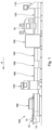
- Fig. 1 represents a folder-gluer machine 100, that is to say a processing machine which is responsible for folding and gluing blanks in order to manufacture folding boxes. Equipped with a modular structure, this folder-gluer 100 is conventionally composed, from upstream to downstream, of a feeder module 110 or margin table, of an alignment module 120, of an embossing module 130 , in particular for Braille, a fold pre-breaking module 140, a gluing module 150, a folding module 160, a transfer module 170 and a reception module 180. cutouts move from upstream to downstream from one module to another in the folder-gluer machine 100, in the longitudinal direction (direction of Arrow A visible on the Figs. 1 And 2 ).
- the folder-gluer 100 is further provided with a control device 10 which is integrated directly between the alignment module 120 and the embossing module 130.
- This control device 10 is intended to carry out online quality control at the within the folder-gluer 100 itself, by systematically inspecting all the cutouts 12 which circulate there with their printed face 13 facing downwards (lower face), and their internal face 14, not printed, facing upwards (face higher).
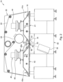
- the control device 10 (see Fig. 2 ) comprises a vacuum conveyor 20.
- the conveyor 20 firstly comprises a conveyor belt 22, which is responsible for continuously conveying each cutout 12.
- Each cutout 12 is conveyed while being held from above at the level of its upper face 14 , intended to constitute the internal face of a box, along a given circulation path 15.
- This conveyor belt 22 is set in motion by the motor 23 in an endless loop.
- the control device 10 also has inspection means 30 making it possible to inspect from below the lower face 13 of each blank 12 during its transport along the circulation path 15 which passes right through the control device. 10, from right to left on the Fig. 2 .
- the inspection means 30 include in particular a camera 32 and a lighting system 31 oriented and converging (see drawn lines in Fig. 2 ) towards the same control zone 33.
- the control zone 33 can for example be in the form of a transverse line or a transversely elongated rectangle located at the level of the circulation path 15.
- the cutout is retained by the conveyor belt 22 along the circulation path 15 which follows the substantially horizontal and flat lower section of the conveyor belt 22. More precisely the cutout 12 is retained by suction against the underside of the conveyor belt 22 by means of the suction means 40 arranged above the conveyor belt 22 along the circulation path 15 of the cutout 12.
- the conveyor belt 22 operates at the level of three distinct sections 41, 42 and 43 of the circulation path 15, crossed successively by the cutout 12.
- An upstream suction section 41 is followed by a central suction section 42, which extends opposite the inspection means 30, and which is followed by a downstream suction section 43.
- the cutout 12 is perfectly pressed against the conveyor belt 22 between the inspection means 30 and the conveyor belt 22.
- Each of the sections, the central suction section 42, the upstream suction section 41 and the downstream suction section 43 comprises a box in which a depression is generated (Arrows V in Fig. 2 ). More precisely, an upstream box 41a, a central box 42a and a downstream box 43a are respectively aligned in the direction of advancement A.
- the boxes 41a, 42a and 43a are located above and behind the conveyor belt 22, itself located above and behind the cutout 12, which is itself located above and behind the inspection means 30, during visual inspection of its lower face 13 printed and/or bearing reliefs .
- the conveyor belt 22 is kept flat and continuous over the entire lower surface extending along the circulation path 15 of the distinct sections 41, 42 and 43 and the boxes 41a, 42a and 43a.
- the central suction box 42a comprises at least one suction opening, the opening(s) opening directly to the control zone 33.
- each box 41a, 42a and 43a can communicate with a vacuum pump.
- This solution with an individual suction pump for the upstream box 41a, the central box 42a and the downstream box 43a is not always possible, in particular for reasons of bulk.
- the presence of three vacuum pumps presents a significant cost.
- the vacuum conveyor 20 comprises a first vacuum pump 44 and a second vacuum pump 45.
- the first vacuum pump 44 is coupled and communicates with the upstream suction box 41a of the upstream suction section 41.
- the second vacuum pump 45 is coupled and communicates both with the central box 42a of the central suction section 42 with the downstream box 43a of the downstream suction section 43.
- the air under vacuum is shared between the central box 42, used to maintain a section of the strip 22 facing the inspection means 30, and the downstream box 43, used to maintain the section of the strip 22 located downstream of the inspection means 30 .
- This sharing of the suction provided by the second vacuum pump 45 can be carried out according to a distribution chosen according to the data and dimensions of the control device 10, and in particular the volume of the central box 42a and the downstream box 43a.
- a distribution chosen according to the data and dimensions of the control device 10, and in particular the volume of the central box 42a and the downstream box 43a For example, less than half of the outlet section of the second vacuum pump 45 is coupled to the central box 42a of the central suction section 42.
- less than a third less of the outlet section of the second vacuum pump 45 is coupled to the central box 42a of the central suction section 42.
- of the order of a third of the outlet section of the second vacuum pump 45 is coupled to the central box 42a of the central suction section 42.
- the central box 42a and the downstream box 43a respectively represent the order of 5% and 95% of the total volume formed by the central box 42a and the downstream box 43a.
- At least one of the upstream box 41a, the central box 42a and the downstream box 43a has an adjustable suction volume.
- the upstream box 41a and the downstream box 43a have a modifiable volume.
- Such modularity is obtained for example by compartmentalizing the upstream 41a and downstream 43a boxes, with internal walls and by equipping the upstream 41a and downstream 43a boxes with a movable shutter at the entrance to each compartment, which can be opened or closed at will.
- the upstream box 41a and the downstream box 43a comprise a lower perforated wall, extending along the circulation path 15; the conveyor belt 22 has a perforated structure, which is able to slide against each perforated wall.
- the strip 22 at least partially covers the width of each perforated wall of the upstream box 41a and the downstream box 43a. According to a preferred arrangement, the strip 22 substantially completely covers the width of each perforated wall of the upstream box 41a and the downstream box 43a.
- the outlet section of the central box 42a is of small amplitude, and is not equipped with a perforated wall.
- the vacuum conveyor 20 comprises tensioning means 50 of the belt 22, ensuring local rigidity of the belt 22.
- These tensioning means 50 comprise a pair of rollers 51 and 52 spaced apart along the circulation path 15. More precisely, each upstream roller 51 and each downstream roller 52 is arranged above the conveyor belt 22. The vacuum generated by the central box 42a will press the belt 22 at the level and against these fixed rollers 51 and 52, which will ensure a flat inspection surface.
- the rollers 51 and 52 are located along the central suction section 42. Furthermore, preferably, the rollers 51 and 52 respectively delimit the upstream position and the downstream position of the central suction section 43. Concretely the outlet of the central box 43a extends along the direction of advancement A between the rollers 51 and 52. For example, the rollers 51 and 52 are spaced from one another along the direction of advancement A d 'a distance of around 30mm, and preferably between 20mm and 50mm.
Description
- La présente invention concerne le domaine de la fabrication d'emballages, et notamment d'emballages fabriqués à partir de feuilles ou de bandes prédécoupées, notamment des découpes de papier, de plastique ou de carton, qu'il soit plat, ondulé ou mixte. De façon non exclusive, la présente invention est utilisée dans le domaine de la fabrication des boîtes pliantes.
- Plus précisément, la présente invention concerne un dispositif permettant de contrôler la qualité de découpes circulant dans une machine de traitement telle qu'une machine plieuse colleuse.
- Dans l'industrie de l'emballage, la fabrication des boîtes pliantes s'effectue traditionnellement en ligne, en pliant et en collant des découpes au moyen de machines communément appelées plieuses-colleuses. A cet égard, il est connu de contrôler la qualité des découpes au sein même de la plieuse-colleuse. Pour cela un module spécifique est utilisé et est directement intégré dans la plieuse-colleuse. Ce module est en mesure d'inspecter individuellement chaque découpe lorsque cette dernière passe à travers le module. Comme le déplacement des découpes s'accomplit faces imprimées tournées vers le bas au sein de la plieuse-colleuse, leur transport à travers le module de contrôle est réalisé en les maintenant par le dessus, tandis que leur inspection s'effectue par le dessous.
- En pratique, le transport par le dessus des découpes s'opère en utilisant un convoyeur vacuum qui associe une pluralité de bandes transporteuses à un caisson vacuum positionné directement au-dessus. chaque découpe est ainsi maintenue par le dessus au niveau de sa face interne, de sorte que sa face imprimée, qui est tournée vers le bas, se trouve entièrement dégagée. L'inspection par le dessous est quant à elle menée au moyen d'une caméra qui est implantée sous le convoyeur vacuum, et qui fonctionne en contre-plongée. Associé à un système d'éclairage adéquat, la caméra effectue une prise de vue de chaque face imprimée au fur et à mesure que les découpes défilent.
- Le document
EP 2578521 peut être cité comme décrivant des machines de l'art antérieur réalisant un tel contrôle. Dans ce cas, le chemin de circulation de la découpe passe dans un tronçon avec un élément d'arrière-plan qui améliore le contrôle du contour et qui se situe entre deux tronçons distinct et légèrement espacés du chemin de circulation, munis chacun d'un caisson dans lequel est générée une dépression pour maintenir la découpe plaquée par sa face supérieure contre une bande transporteuse, tandis que sa face inférieure imprimée est contrôlée. De cette façon, non seulement des défauts présents à l'intérieur de la découpe, mais également des défauts des défauts présents sur le contour de la découpe sont en mesure d'être détectés. Les défauts sont définis à titre d'exemple comme étant notamment respectivement des erreurs d'impression dans le texte, les couleurs, le registre des couleurs, etc., des erreurs d'embossage, d'autres défauts d'aspect, tels que des trous, des cassures, des déchirures, etc., des erreurs de découpe, des taches d'huile, et d'autres encore. - Cependant, cette technique apporte une instabilité de position de la découpe du fait que dans la zone de l'élément d'arrière-plan, d'étendue certes très inférieure à la longueur de la découpe, cette dernière n'est pas maintenue par aspiration. En effet, au cours de l'avancée de la découpe depuis la section amont du convoyeur vacuum vers la section aval du convoyeur vacuum, la découpe est en porte-à-faux lorsque son bord avant puis son bord arrière n'est plus aspiré.
- Un but de la présente invention est de proposer un dispositif de contrôle amélioré qui assure une position stable de la découpe lorsqu'elle passe devant les moyens d'inspection et de contrôle de sa surface.
- Selon l'invention, ces buts sont atteints au moyen d'un dispositif de contrôle optique d'une face d'une découpe, selon la revendication 1, comprenant:
- un convoyeur vacuum, qui est apte à transporter la découpe le long d'un chemin de circulation, et le convoyeur vacuum comportant
une bande transporteuse, ayant une structure ajourée dont le trajet de défilement suit le chemin de circulation de la découpe, et
des moyens d'aspiration, qui sont aptes à plaquer la découpe contre la bande transporteuse, et - des moyens pour inspecter la face de la découpe au cours de son transport par le convoyeur vacuum, les moyens pour inspecter étant situés du côté opposé au convoyeur vacuum,
- Le dispositif de contrôle optique comprenant des moyens d'aspiration qui délimitent trois tronçons d'aspiration distincts successifs le long du chemin de circulation, parmi lesquels un tronçon d'aspiration central qui s'étend en regard des moyens d'inspection, un tronçon d'aspiration amont et un tronçon d'aspiration aval.
- Un tel dispositif permet de réguler la dépression permettant d'aspirer et de retenir la découpe contre bande transporteuse au niveau du tronçon d'aspiration central et donc au niveau des moyens d'inspection. Ainsi, l'intensité de dépression la plus adaptée peut être choisie pour stabiliser la découpe en vue de son contrôle par les moyens d'inspection.
- Selon une disposition avantageuse, le dispositif de contrôle comprend en outre, en regard des moyens d'inspection, des moyens de mise en tension de la bande transporteuse. De cette façon, la tenue et la rigidité de la bande sont améliorées en regard des moyens d'inspection, ce qui empêche des mouvements et/ou changements d'orientation de la découpe lorsqu'elle passe devant les moyens d'inspection. En particulier, ces moyens de mise en tension peuvent être agencés pour garantir une planéité de la bande transporteuse afin que la position de la découpe sur la bande permette un contrôle optique optimal, grâce à une orientation maîtrisée et constante de la découpe par rapport d'une part au système d'éclairage et d'autre part à la caméra.
- Par ailleurs, l'invention peut être mise en oeuvre quelle que soit la direction de déplacement des découpes, en adaptant en conséquence l'agencement de la bande transporteuse, des moyens d'inspection et des moyens d'aspiration, le long du chemin de circulation des découpes.
- Ainsi, un tel dispositif de contrôle peut se faire pendant le déplacement de chaque découpe qui est réalisé avec la face imprimée tournée vers le bas, par exemple en maintenant la découpe par le dessus, tandis que l'inspection de la face imprimée s'effectue par le dessous.
- Selon une autre possibilité, il est possible d'agencer le dispositif de contrôle selon l'invention de manière à ce que chaque découpe se déplace via la bande transporteuse avec sa face imprimée orientée vers le haut, de sorte que l'inspection s'effectue par le dessus, et par exemple le maintien de la découpe s'effectue par le dessous.
- Le dispositif de contrôle est également possible dans le cas où le déplacement des découpes est réalisé dans un plan sensiblement vertical.
- La présente invention se rapporte également à une machine de traitement de découpes selon la revendication 12, et à une machine plieuse-colleuse selon la revendication 13, équipées d'un dispositif de contrôle selon la revendication 1.
- Des exemples de mise en oeuvre de l'invention sont indiqués dans la description illustrée par les figures annexées dans lesquelles:
- la
Figure 1 représente de manière schématique une plieuse-colleuse dans laquelle est intégré un dispositif de contrôle conforme à l'invention; et - la
Figure 2 est une vue en coupe longitudinale du dispositif de contrôle selon l'invention. - La
Fig. 1 représente une machine plieuse-colleuse 100, c'est-à-dire une machine de traitement qui est chargée de plier et de coller des découpes en vue de fabriquer des boîtes pliantes. Dotée d'une structure modulaire, cette plieuse-colleuse 100 est classiquement composée, d'amont en aval, d'un module margeur 110 ou table de marge, d'un module d'alignement 120, d'un module d'embossage 130, notamment pour du braille, d'un module de précassage des plis 140, d'un module d'encollage 150, d'un module de pliage 160, d'un module de transfert 170 et d'un module de réception 180. Les découpes se déplacent de l'amont vers l'aval d'un module à l'autre dans la machine plieuse-colleuse 100, selon la direction longitudinale (sens de la Flèche A visible sur lesFigs. 1 et2 ). - La plieuse-colleuse 100 est en outre pourvue d'un dispositif de contrôle 10 qui est intégré directement entre le module d'alignement 120 et le module d'embossage 130. Ce dispositif de contrôle 10 est destiné à réaliser un contrôle qualité en ligne au sein même de la plieuse-colleuse 100, en inspectant de manière systématique toutes les découpes 12 qui y circulent avec leur face imprimée 13 tournées vers le bas (face inférieure), et leur face interne 14, non imprimée, orientée vers le haut (face supérieure).
- Le dispositif de contrôle 10 (voir
Fig. 2 ) comprend un convoyeur vacuum 20. Le convoyeur 20 comprend tout d'abord une bande transporteuse 22, qui est chargée de convoyer de façon continue chaque découpe 12. Chaque découpe 12 est convoyée en étant maintenue par le dessus au niveau de sa face supérieure 14, destinée à constituer la face interne d'une boîte, le long d'un chemin de circulation donné 15. Cette bande transporteuse 22 est mise en mouvement par le moteur 23 selon une boucle sans fin. - Le plus souvent, la face inférieure 13 de la découpe 12 à inspecter est pourvue de signes, qu'ils soient en relief, des creux et/ou des bosses, et/ou imprimés avec des textes, des images, etc. et de manière générale tout type de symboles. Le dispositif de contrôle 10 présente également des moyens d'inspection 30 permettant d'inspecter par le dessous la face inférieure 13 de chaque découpe 12 au cours de son transport le long du chemin de circulation 15 qui traverse de part en part le dispositif de contrôle 10, de la droite vers la gauche sur la
Fig. 2 . Les moyens d'inspection 30 comportent notamment une caméra 32 et un système d'éclairage 31 orientés et convergeant (cf. traits tillés enFig. 2 ) vers une même zone de contrôle 33. La zone de contrôle 33 peut par exemple se présenter sous la forme d'une ligne transversale ou d'un rectangle allongé transversalement situé au niveau du chemin de circulation 15. - Ainsi, lors de son avancée continue dans le dispositif de contrôle 10, la découpe est retenue par la bande transporteuse 22 le long du chemin de circulation 15 qui suit le tronçon inférieur sensiblement horizontal et plan de la bande transporteuse 22. Plus précisément la découpe 12 est retenue par aspiration contre la face inférieure de la bande transporteuse 22 au moyen des moyens d'aspiration 40 disposés au-dessus de la bande transporteuse 22 le long du chemin de circulation 15 de la découpe 12.
- Conformément à l'objet de la présente invention, la bande transporteuse 22 est opérante au niveau de trois tronçons distincts 41, 42 et 43 du chemin de circulation 15, traversés successivement par la découpe 12. Un tronçon d'aspiration amont 41, est suivie par un tronçon d'aspiration central 42, qui s'étend en regard des moyens d'inspection 30, et qui est suivi par un tronçon d'aspiration aval 43. De cette façon, lors du contrôle, la découpe 12 se trouve parfaitement plaquée contre la bande transporteuse 22 entre les moyens d'inspection 30 et la bande transporteuse 22.
- Chacun des tronçons, le tronçon d'aspiration central 42, le tronçon d'aspiration amont 41 et le tronçon d'aspiration aval 43, comporte un caisson dans lequel est générée une dépression (Flèches V en
Fig. 2 ). Plus précisément, un caisson amont 41a, un caisson central 42a et un caisson aval 43a, sont respectivement alignés selon la direction d'avancement A. Les caissons 41a, 42a et 43a sont situés au-dessus et en arrière de la bande transporteuse 22, elle-même située au-dessus et en arrière de la découpe 12, qui est elle-même située au-dessus et en arrière des moyens d'inspection 30, lors du contrôle visuelle de sa face inférieure 13 imprimée et/ou portant des reliefs. - La bande transporteuse 22 est maintenue plane et continue sur toute la surface inférieure s'étendant le long du chemin de circulation 15 des tronçons distincts 41, 42 et 43 et des caissons 41a, 42a et 43a. Le caisson d'aspiration central 42a comprend au moins une ouverture d'aspiration, la ou les ouvertures débouchant directement au niveau de la zone de contrôle 33.
- Selon un mode de réalisation non représenté, chaque caisson 41a, 42a et 43a peut communiquer avec une pompe à dépression. Cette solution avec une pompe d'aspiration individuelle pour le caisson amont 41a, le caisson central 42a et le caisson aval 43a n'est pas toujours possible, notamment pour des raisons d'encombrement. De plus la présence de trois pompes à dépression présente un coût important.
- Le convoyeur vacuum 20 comporte une première pompe à dépression 44 et une deuxième pompe à dépression 45. La première pompe à dépression 44 est couplée et communique avec le caisson d'aspiration amont 41a du tronçon d'aspiration amont 41. La deuxième pompe à dépression 45 est couplée et communique à la fois avec le caisson central 42a du tronçon d'aspiration central 42 avec le caisson aval 43a du tronçon d'aspiration aval 43. A la sortie de la deuxième pompe à dépression 45 l'air sous dépression se partage entre le caisson central 42, servant au maintien d'un tronçon de la bande 22 faisant face aux moyens d'inspection 30, et le caisson aval 43, servant au maintien du tronçon de la bande 22 situés en aval des moyens d'inspection 30.
- Ce partage de l'aspiration fournie par la deuxième pompe à dépression 45 peut s'effectuer selon une répartition choisie en fonctions des données et dimensions du dispositif de contrôle 10, et notamment du volume du caisson central 42a et du caisson aval 43a. Par exemple, moins de la moitié de la section de sortie de la deuxième pompe à dépression 45 est couplée au caisson central 42a du tronçon d'aspiration central 42. Selon un autre agencement possible, moins de un tiers moins de la section de sortie de la deuxième pompe à dépression 45 est couplée au caisson central 42a du tronçon d'aspiration central 42. Selon une disposition préférentielle telle que représentée sur la
Fig. 2 , de l'ordre de un tiers de la section de sortie de la deuxième pompe à dépression 45 est couplée au caisson central 42a du tronçon d'aspiration central 42. Dans ce cas, le caisson central 42a et le caisson aval 43a représentent respectivement de l'ordre de 5% et 95% du volume total formé par le caisson central 42a et le caisson aval 43a. - Selon une disposition avantageuse, au moins un parmi le caisson amont 41a, le caisson central 42a et le caisson aval 43a présente un volume d'aspiration réglable. Selon une disposition préférentielle telle que représentée sur la
Fig. 2 , le caisson amont 41a et le caisson aval 43a présentent un volume modifiable. Une telle modularité s'obtient par exemple en compartimentant les caissons amont 41a et aval 43a, avec des parois internes et en équipant les caissons amont 41a et aval 43a avec un volet mobile à l'entrée de chaque compartiment, qui peut être ouvert ou fermé à volonté. En alternative, comme dans le cas de laFig. 2 , ce sont les panneaux latéraux du caisson amont 41a (aval 43a) qui s'étendent selon la direction d'avancement A, qui sont coulissants afin de pouvoir élargir ou rétrécir la largeur du caisson amont 41a (aval 43a). - De façon classique, le caisson amont 41a et le caisson aval 43a comprennent une paroi ajourée inférieure, s'étendant le long du chemin de circulation 15 la bande transporteuse 22 présente une structure perforée, qui est apte à glisser contre chaque paroi ajourée. La bande 22 recouvre au moins partiellement la largeur de chaque paroi ajourée du caisson amont 41a et du caisson aval 43a. Selon une disposition préférentielle, la bande 22 recouvre sensiblement complètement la largeur de chaque paroi ajourée du caisson amont 41a et du caisson aval 43a. La section de sortie du caisson central 42a est de faible amplitude, et n'est pas équipée avec une paroi ajourée.
- Le convoyeur vacuum 20 comprend des moyens de mise en tension 50 de la bande 22, assurant une rigidité locale de la bande 22. Ces moyens de mise en tension 50 comportent une paire de galets 51 et 52 écartés le long du chemin de circulation 15. Plus précisément, chaque galet amont 51 et chaque galet aval 52 est disposé au-dessus de la bande transporteuse 22. Le vacuum généré par le caisson central 42a va plaquer la bande 22 au niveau et contre ces galets fixes 51 et 52, ce qui va garantir une surface d'inspection plane.
- Ainsi, les galets 51 et 52 sont situés le long du tronçon d'aspiration central 42. Par ailleurs, de préférence, les galets 51 et 52 délimitent respectivement la position amont et la position aval du tronçon d'aspiration central 43. Concrètement la sortie du caisson central 43a s'étend le long de la direction d'avancement A entre les galets 51 et 52. Par exemple, les galets 51 et 52 sont espacés l'un de l'autre le long de la direction d'avancement A d'une distance de l'ordre de 30mm, et de préférence entre 20mm et 50mm.
- La présente invention n'est pas limitée aux modes de réalisation décrits et illustrés. De nombreuses modifications peuvent être réalisées, sans pour autant sortir du cadre défini par la portée du jeu de revendications.
Claims (12)
- Dispositif de contrôle optique (10) d'une face (13) d'une découpe (12), comprenant:- un convoyeur vacuum (20), apte à transporter la découpe (12) le long d'un chemin de circulation (15), et comportant- une bande transporteuse (22) de structure ajourée dont le trajet de défilement suit le chemin de circulation (15) de la découpe (12), et- des moyens d'aspiration (40), qui sont aptes à plaquer la découpe (12) contre la bande transporteuse (14), et délimitant un tronçon d'aspiration amont (41) et un tronçon d'aspiration aval (43),- des moyens (30) pour inspecter la face (13) de la découpe (12) au cours de son transport par le convoyeur vacuum (20), situés du côté opposé au convoyeur vacuum (20),caractérisé en ce que les moyens d'aspiration (40) délimitent trois tronçons d'aspiration (41, 42, 43) distincts successifs le long du chemin de circulation (15), parmi lesquels un tronçon d'aspiration central (42), qui s'étend en regard des moyens d'inspection (30), le tronçon d'aspiration amont (41) et le tronçon d'aspiration aval (43), le tronçon d'aspiration amont (41), le tronçon d'aspiration central (42) et le tronçon d'aspiration aval (43) comportant chacun un caisson (41a, 42a, 43a) dans lequel est généré une dépression, le caisson d'aspiration central (42a) comprenant au moins une ouverture d'aspiration, la ou les ouvertures débouchant directement au niveau d'une zone de contrôle (33), la bande transporteuse (22) étant maintenue plane et continue sur toute la surface inférieure s'étendant le long du chemin de circulation (15) des tronçons distincts (41, 42, 43) et des caissons (41a, 42a, 43a).
- Dispositif selon la revendication 1, comprenant en outre, en regard des moyens d'inspection (30), des moyens de mise en tension (50) de la bande (22).
- Dispositif selon la revendication 2, dans lequel les moyens de mise en tension (50) comportent une paire de galets (51, 52) écartés le long du chemin de circulation (15).
- Dispositif selon la revendication 3, dans lequel les galets (51, 52) sont situés le long du tronçon d'aspiration central (42).
- Dispositif selon la revendication 4, dans lequel les galets (51, 52) délimitent la position amont et aval du tronçon d'aspiration central (42).
- Dispositif selon l'une des revendications précédentes, dans lequel le caisson (41a, 42a, 43a) communique avec une pompe à dépression.
- Dispositif selon la revendication 6, comprenant une première pompe à dépression (44) couplée à la fois avec le caisson amont (41a) du tronçon d'aspiration amont (41) et avec le caisson central (42a) du tronçon d'aspiration central (42), et une deuxième pompe à dépression (45) qui communique avec le caisson aval (43a) du tronçon d'aspiration aval (43).
- Dispositif selon la revendication 7, dans lequel moins de la moitié de la section de sortie de la deuxième pompe à dépression (45) est couplée au caisson central (42a) du tronçon d'aspiration central (42).
- Dispositif selon l'une des revendications 6 à 8, dans lequel l'un au moins des caissons (41a, 42a, 43a) présente un volume d'aspiration réglable.
- Dispositif selon l'une des revendications 7 à 9, dans lequel le caisson amont (41a) et le caisson aval (43a) comprennent une paroi ajourée s'étendant le long du chemin de circulation (15), et en ce que la bande (22) présente une structure perforée qui est apte à glisser contre la paroi ajourée.
- Machine de traitement de découpes (100) équipée d'un dispositif de contrôle (10) selon l'une des revendications précédentes.
- Machine plieuse-colleuse équipée d'un dispositif de contrôle (10) selon l'une des revendications 1 à 10.
Priority Applications (1)
| Application Number | Priority Date | Filing Date | Title |
|---|---|---|---|
| PL15797861T PL3221221T3 (pl) | 2014-11-19 | 2015-11-10 | Urządzenie do kontroli optycznej jednej strony wykroju, maszyna do obróbki wykrojów oraz składarko-sklejarka zawierająca takie urządzenie |
Applications Claiming Priority (2)
| Application Number | Priority Date | Filing Date | Title |
|---|---|---|---|
| EP14020088 | 2014-11-19 | ||
| PCT/EP2015/025078 WO2016078776A1 (fr) | 2014-11-19 | 2015-11-10 | Dispositif de contrôle optique d'une face d'une découpe |
Publications (3)
| Publication Number | Publication Date |
|---|---|
| EP3221221A1 EP3221221A1 (fr) | 2017-09-27 |
| EP3221221B1 EP3221221B1 (fr) | 2019-03-20 |
| EP3221221B2 true EP3221221B2 (fr) | 2024-03-06 |
Family
ID=52016369
Family Applications (1)
| Application Number | Title | Priority Date | Filing Date |
|---|---|---|---|
| EP15797861.0A Active EP3221221B2 (fr) | 2014-11-19 | 2015-11-10 | Dispositif de contrôle optique d'une face d'une découpe, machine de traitement de découpes et plieuse-colleuse comprenant le dispositif. |
Country Status (9)
| Country | Link |
|---|---|
| US (1) | US10647458B2 (fr) |
| EP (1) | EP3221221B2 (fr) |
| JP (1) | JP6560350B2 (fr) |
| KR (1) | KR102571872B1 (fr) |
| CN (2) | CN113103661A (fr) |
| ES (1) | ES2721780T3 (fr) |
| PL (1) | PL3221221T3 (fr) |
| TR (1) | TR201905630T4 (fr) |
| WO (1) | WO2016078776A1 (fr) |
Citations (9)
| Publication number | Priority date | Publication date | Assignee | Title |
|---|---|---|---|---|
| EP0888992A2 (fr) † | 1997-07-01 | 1999-01-07 | MAN Roland Druckmaschinen AG | Table de marge pour l'alimentation cadencée de feuilles dans une machine à traiter des feuilles |
| DE69511300T2 (de) † | 1994-02-04 | 2000-02-10 | De La Rue Giori Sa | Qualitätskontroll-Anlage für gedruckte Blätter, insbesondere Wertpapiere |
| WO2001014235A1 (fr) † | 1999-08-20 | 2001-03-01 | Koenig & Bauer Aktiengesellschaft | Procede et dispositif pour traiter des papiers-valeurs |
| DE102004005232A1 (de) † | 2003-02-24 | 2006-02-16 | Heidelberger Druckmaschinen Ag | Saugbandmodul mit einem Gebläse |
| EP2241523A1 (fr) † | 2008-01-10 | 2010-10-20 | Seiko I Infotech Inc. | Corps de transport et dispositif de transport |
| DE102009032966A1 (de) † | 2009-07-14 | 2011-01-20 | Gmg Grafische Maschinen Gesellschaft Mbh | Vorrichtung zur Behandlung bogenförmiger Substrate mit Licht |
| DE102011108018A1 (de) † | 2010-08-31 | 2012-03-01 | Heidelberger Druckmaschinen Ag | Inspektionsmodul |
| DE102011120993A1 (de) † | 2011-01-19 | 2012-07-19 | Heidelberger Druckmaschinen Ag | Saugbandtisch |
| EP2578521A1 (fr) † | 2011-10-03 | 2013-04-10 | Bobst Mex Sa | Dispositif de controle pour machine de traitment de découpes |
Family Cites Families (9)
| Publication number | Priority date | Publication date | Assignee | Title |
|---|---|---|---|---|
| DE4442629C2 (de) * | 1994-12-01 | 1998-05-07 | Heidelberger Druckmasch Ag | Saugbändertisch |
| DE10008831C2 (de) | 2000-02-25 | 2003-12-04 | Daimler Chrysler Ag | Fördervorrichtung für den hängenden Transport von flachen Gegenständen, insbesondere von metallischen Platinen |
| DE10057036C2 (de) * | 2000-11-17 | 2002-12-12 | Basler Ag | Inspektionssystem für Flachgläser in der Displayfertigung |
| JP4571812B2 (ja) * | 2003-02-24 | 2010-10-27 | ハイデルベルガー ドルツクマシーネン アクチエンゲゼルシヤフト | シート搬送装置 |
| CN2925861Y (zh) * | 2006-04-28 | 2007-07-25 | 上海今昌纸箱机械制造有限公司 | 一种自动送纸部的瓦楞强度无损型的传送纸机构 |
| JP4977596B2 (ja) | 2007-06-26 | 2012-07-18 | 株式会社名南製作所 | 定形のシート類の搬送方法及び搬送装置 |
| FI20070654A0 (fi) * | 2007-08-29 | 2007-08-29 | Raute Oyj | Laitteisto levymäisten esineiden siirtämiseksi |
| US8157369B2 (en) * | 2010-05-26 | 2012-04-17 | Xerox Corporation | Media hold-down system having cross process chambering |
| CN102583076A (zh) * | 2012-03-09 | 2012-07-18 | 天津长荣印刷设备股份有限公司 | 一种风箱的幅面调节装置及其工作方法 |
-
2015
- 2015-11-10 JP JP2017526661A patent/JP6560350B2/ja active Active
- 2015-11-10 TR TR2019/05630T patent/TR201905630T4/tr unknown
- 2015-11-10 CN CN202110226845.2A patent/CN113103661A/zh active Pending
- 2015-11-10 PL PL15797861T patent/PL3221221T3/pl unknown
- 2015-11-10 WO PCT/EP2015/025078 patent/WO2016078776A1/fr active Application Filing
- 2015-11-10 EP EP15797861.0A patent/EP3221221B2/fr active Active
- 2015-11-10 ES ES15797861T patent/ES2721780T3/es active Active
- 2015-11-10 KR KR1020177015828A patent/KR102571872B1/ko active IP Right Grant
- 2015-11-10 CN CN201580068348.7A patent/CN107000866A/zh active Pending
- 2015-11-10 US US15/527,205 patent/US10647458B2/en active Active
Patent Citations (9)
| Publication number | Priority date | Publication date | Assignee | Title |
|---|---|---|---|---|
| DE69511300T2 (de) † | 1994-02-04 | 2000-02-10 | De La Rue Giori Sa | Qualitätskontroll-Anlage für gedruckte Blätter, insbesondere Wertpapiere |
| EP0888992A2 (fr) † | 1997-07-01 | 1999-01-07 | MAN Roland Druckmaschinen AG | Table de marge pour l'alimentation cadencée de feuilles dans une machine à traiter des feuilles |
| WO2001014235A1 (fr) † | 1999-08-20 | 2001-03-01 | Koenig & Bauer Aktiengesellschaft | Procede et dispositif pour traiter des papiers-valeurs |
| DE102004005232A1 (de) † | 2003-02-24 | 2006-02-16 | Heidelberger Druckmaschinen Ag | Saugbandmodul mit einem Gebläse |
| EP2241523A1 (fr) † | 2008-01-10 | 2010-10-20 | Seiko I Infotech Inc. | Corps de transport et dispositif de transport |
| DE102009032966A1 (de) † | 2009-07-14 | 2011-01-20 | Gmg Grafische Maschinen Gesellschaft Mbh | Vorrichtung zur Behandlung bogenförmiger Substrate mit Licht |
| DE102011108018A1 (de) † | 2010-08-31 | 2012-03-01 | Heidelberger Druckmaschinen Ag | Inspektionsmodul |
| DE102011120993A1 (de) † | 2011-01-19 | 2012-07-19 | Heidelberger Druckmaschinen Ag | Saugbandtisch |
| EP2578521A1 (fr) † | 2011-10-03 | 2013-04-10 | Bobst Mex Sa | Dispositif de controle pour machine de traitment de découpes |
Non-Patent Citations (10)
| Title |
|---|
| B7921EP Bobst Drawing 2011 † |
| Déclaratiion de Dr. Kaupp † |
| Déclaration de Christoph Kreiser, directeur général de „Grafisches Centrum » † |
| Déclaration de Dr. Ansgar Kaupp † |
| Déclaration de Dr.-lng. Roland Schrôder † |
| Déclaration de Dr.-lng. Stefan Lambertz † |
| Déclaration de Matthias Bauer, directeur général de la „db bauer packaging Druckerei Bauer GmbH" † |
| Déclaration de Michael Kohmann. directeur général de la ..Kohmanr GmbH & Co.KG Maschinenbau" † |
| Dessins techniques du bidule de la D3 et D4 † |
| Photos de la Interpack 20014, 8-10.05.2014 † |
Also Published As
| Publication number | Publication date |
|---|---|
| US20170320607A1 (en) | 2017-11-09 |
| PL3221221T3 (pl) | 2019-07-31 |
| WO2016078776A1 (fr) | 2016-05-26 |
| KR102571872B1 (ko) | 2023-08-28 |
| EP3221221B1 (fr) | 2019-03-20 |
| JP2017536545A (ja) | 2017-12-07 |
| TR201905630T4 (tr) | 2019-05-21 |
| EP3221221A1 (fr) | 2017-09-27 |
| KR20170087902A (ko) | 2017-07-31 |
| ES2721780T3 (es) | 2019-08-05 |
| CN113103661A (zh) | 2021-07-13 |
| CN107000866A (zh) | 2017-08-01 |
| JP6560350B2 (ja) | 2019-08-14 |
| US10647458B2 (en) | 2020-05-12 |
Similar Documents
| Publication | Publication Date | Title |
|---|---|---|
| EP2640558B1 (fr) | Dispositif pour une unite d'ejection des dechets dans une machine de production d'emballages | |
| EP3038954A1 (fr) | Procédé et dispositif pour transporter et tourner des objets plats | |
| EP1640146B1 (fr) | Dispositif d'assemblage d'éléments en plaque pour une machine de fabrication de boîtes | |
| EP2976279B1 (fr) | Dispositif d'ejection d'un objet plat en cours de convoyage | |
| EP3519305B1 (fr) | Dispositif d'ecartement de rabat avant remplissage pour des recipients d'emballage tels que cartons et station de remplissage equipee | |
| EP3224038B1 (fr) | Procede et dispositif de correction de la position repliee d'une decoupe dans une plieuse-colleuse | |
| EP2964434B1 (fr) | Agencement de découpe et d'éjection des déchets, unité et machine ainsi équipée | |
| EP3612483B1 (fr) | Dispositif et procédé de contrôle d'échantillons de poses, station d'évacuation, et machine de traitement d'éléments en forme de feuilles | |
| EP3612484B1 (fr) | Dispositif de recuperation d'echantillons de poses, station d'evacuation et machine de traitement d'elements en forme de feuilles | |
| EP3221221B2 (fr) | Dispositif de contrôle optique d'une face d'une découpe, machine de traitement de découpes et plieuse-colleuse comprenant le dispositif. | |
| EP2964556B1 (fr) | Dispositif de transport d'elements plats | |
| FR2715642A1 (fr) | Dispositif pour tourner des pièces reposant à plat pendant leur avance. | |
| FR3041888A1 (fr) | Machine et procede de revetement de peinture pour profiles pvc | |
| FR2939421A1 (fr) | Dispositif ascenseur pour machine de personnalisation et machine de personnalisation munie d'un dispositif ascenseur | |
| EP3169528B1 (fr) | Caisson d'aspiration, systeme de transport de supports plans, et machine d'impression ainsi equipee | |
| EP2844460B1 (fr) | Module avec bâti et plieuse-colleuse ainsi équipée | |
| WO1988003580A1 (fr) | Machine de pliage d'articles textiles | |
| WO2018072886A1 (fr) | Dispositif et procédé de déviation et d'échantillonnage pour élément en plaque | |
| FR3041887A1 (fr) | Machine et procede de revetement de peinture pour profiles pvc | |
| EP3224039B1 (fr) | Procede et dispositif de correction de la position d'une decoupe repliee dans une plieuse-colleuse | |
| WO2015192863A1 (fr) | Procede, dispositif de rotation d'objets plans, module et machine de traitement ainsi equipee | |
| FR2765554A1 (fr) | Machine permettant d'ouvrir des boites en carton de maniere automatisee | |
| FR3063973A1 (fr) | Machine d'emballage et de conditionnement | |
| EP2578521A1 (fr) | Dispositif de controle pour machine de traitment de découpes | |
| FR3048898A1 (fr) | Procede et installation de traitement de panneau ou plaque |
Legal Events
| Date | Code | Title | Description |
|---|---|---|---|
| STAA | Information on the status of an ep patent application or granted ep patent |
Free format text: STATUS: THE INTERNATIONAL PUBLICATION HAS BEEN MADE |
|
| PUAI | Public reference made under article 153(3) epc to a published international application that has entered the european phase |
Free format text: ORIGINAL CODE: 0009012 |
|
| STAA | Information on the status of an ep patent application or granted ep patent |
Free format text: STATUS: REQUEST FOR EXAMINATION WAS MADE |
|
| 17P | Request for examination filed |
Effective date: 20170518 |
|
| AK | Designated contracting states |
Kind code of ref document: A1 Designated state(s): AL AT BE BG CH CY CZ DE DK EE ES FI FR GB GR HR HU IE IS IT LI LT LU LV MC MK MT NL NO PL PT RO RS SE SI SK SM TR |
|
| AX | Request for extension of the european patent |
Extension state: BA ME |
|
| DAV | Request for validation of the european patent (deleted) | ||
| DAX | Request for extension of the european patent (deleted) | ||
| GRAP | Despatch of communication of intention to grant a patent |
Free format text: ORIGINAL CODE: EPIDOSNIGR1 |
|
| STAA | Information on the status of an ep patent application or granted ep patent |
Free format text: STATUS: GRANT OF PATENT IS INTENDED |
|
| INTG | Intention to grant announced |
Effective date: 20190109 |
|
| GRAS | Grant fee paid |
Free format text: ORIGINAL CODE: EPIDOSNIGR3 |
|
| GRAA | (expected) grant |
Free format text: ORIGINAL CODE: 0009210 |
|
| STAA | Information on the status of an ep patent application or granted ep patent |
Free format text: STATUS: THE PATENT HAS BEEN GRANTED |
|
| AK | Designated contracting states |
Kind code of ref document: B1 Designated state(s): AL AT BE BG CH CY CZ DE DK EE ES FI FR GB GR HR HU IE IS IT LI LT LU LV MC MK MT NL NO PL PT RO RS SE SI SK SM TR |
|
| REG | Reference to a national code |
Ref country code: GB Ref legal event code: FG4D Free format text: NOT ENGLISH |
|
| REG | Reference to a national code |
Ref country code: CH Ref legal event code: EP |
|
| REG | Reference to a national code |
Ref country code: DE Ref legal event code: R096 Ref document number: 602015026851 Country of ref document: DE |
|
| REG | Reference to a national code |
Ref country code: AT Ref legal event code: REF Ref document number: 1110290 Country of ref document: AT Kind code of ref document: T Effective date: 20190415 |
|
| REG | Reference to a national code |
Ref country code: IE Ref legal event code: FG4D Free format text: LANGUAGE OF EP DOCUMENT: FRENCH |
|
| REG | Reference to a national code |
Ref country code: NL Ref legal event code: MP Effective date: 20190320 |
|
| PG25 | Lapsed in a contracting state [announced via postgrant information from national office to epo] |
Ref country code: LT Free format text: LAPSE BECAUSE OF FAILURE TO SUBMIT A TRANSLATION OF THE DESCRIPTION OR TO PAY THE FEE WITHIN THE PRESCRIBED TIME-LIMIT Effective date: 20190320 Ref country code: SE Free format text: LAPSE BECAUSE OF FAILURE TO SUBMIT A TRANSLATION OF THE DESCRIPTION OR TO PAY THE FEE WITHIN THE PRESCRIBED TIME-LIMIT Effective date: 20190320 Ref country code: NO Free format text: LAPSE BECAUSE OF FAILURE TO SUBMIT A TRANSLATION OF THE DESCRIPTION OR TO PAY THE FEE WITHIN THE PRESCRIBED TIME-LIMIT Effective date: 20190620 Ref country code: FI Free format text: LAPSE BECAUSE OF FAILURE TO SUBMIT A TRANSLATION OF THE DESCRIPTION OR TO PAY THE FEE WITHIN THE PRESCRIBED TIME-LIMIT Effective date: 20190320 |
|
| REG | Reference to a national code |
Ref country code: ES Ref legal event code: FG2A Ref document number: 2721780 Country of ref document: ES Kind code of ref document: T3 Effective date: 20190805 |
|
| REG | Reference to a national code |
Ref country code: LT Ref legal event code: MG4D |
|
| PG25 | Lapsed in a contracting state [announced via postgrant information from national office to epo] |
Ref country code: RS Free format text: LAPSE BECAUSE OF FAILURE TO SUBMIT A TRANSLATION OF THE DESCRIPTION OR TO PAY THE FEE WITHIN THE PRESCRIBED TIME-LIMIT Effective date: 20190320 Ref country code: BG Free format text: LAPSE BECAUSE OF FAILURE TO SUBMIT A TRANSLATION OF THE DESCRIPTION OR TO PAY THE FEE WITHIN THE PRESCRIBED TIME-LIMIT Effective date: 20190620 Ref country code: HR Free format text: LAPSE BECAUSE OF FAILURE TO SUBMIT A TRANSLATION OF THE DESCRIPTION OR TO PAY THE FEE WITHIN THE PRESCRIBED TIME-LIMIT Effective date: 20190320 Ref country code: GR Free format text: LAPSE BECAUSE OF FAILURE TO SUBMIT A TRANSLATION OF THE DESCRIPTION OR TO PAY THE FEE WITHIN THE PRESCRIBED TIME-LIMIT Effective date: 20190621 Ref country code: NL Free format text: LAPSE BECAUSE OF FAILURE TO SUBMIT A TRANSLATION OF THE DESCRIPTION OR TO PAY THE FEE WITHIN THE PRESCRIBED TIME-LIMIT Effective date: 20190320 Ref country code: LV Free format text: LAPSE BECAUSE OF FAILURE TO SUBMIT A TRANSLATION OF THE DESCRIPTION OR TO PAY THE FEE WITHIN THE PRESCRIBED TIME-LIMIT Effective date: 20190320 |
|
| REG | Reference to a national code |
Ref country code: AT Ref legal event code: MK05 Ref document number: 1110290 Country of ref document: AT Kind code of ref document: T Effective date: 20190320 |
|
| PG25 | Lapsed in a contracting state [announced via postgrant information from national office to epo] |
Ref country code: PT Free format text: LAPSE BECAUSE OF FAILURE TO SUBMIT A TRANSLATION OF THE DESCRIPTION OR TO PAY THE FEE WITHIN THE PRESCRIBED TIME-LIMIT Effective date: 20190720 Ref country code: AL Free format text: LAPSE BECAUSE OF FAILURE TO SUBMIT A TRANSLATION OF THE DESCRIPTION OR TO PAY THE FEE WITHIN THE PRESCRIBED TIME-LIMIT Effective date: 20190320 Ref country code: CZ Free format text: LAPSE BECAUSE OF FAILURE TO SUBMIT A TRANSLATION OF THE DESCRIPTION OR TO PAY THE FEE WITHIN THE PRESCRIBED TIME-LIMIT Effective date: 20190320 Ref country code: EE Free format text: LAPSE BECAUSE OF FAILURE TO SUBMIT A TRANSLATION OF THE DESCRIPTION OR TO PAY THE FEE WITHIN THE PRESCRIBED TIME-LIMIT Effective date: 20190320 Ref country code: RO Free format text: LAPSE BECAUSE OF FAILURE TO SUBMIT A TRANSLATION OF THE DESCRIPTION OR TO PAY THE FEE WITHIN THE PRESCRIBED TIME-LIMIT Effective date: 20190320 |
|
| PG25 | Lapsed in a contracting state [announced via postgrant information from national office to epo] |
Ref country code: SM Free format text: LAPSE BECAUSE OF FAILURE TO SUBMIT A TRANSLATION OF THE DESCRIPTION OR TO PAY THE FEE WITHIN THE PRESCRIBED TIME-LIMIT Effective date: 20190320 |
|
| REG | Reference to a national code |
Ref country code: DE Ref legal event code: R026 Ref document number: 602015026851 Country of ref document: DE |
|
| PG25 | Lapsed in a contracting state [announced via postgrant information from national office to epo] |
Ref country code: IS Free format text: LAPSE BECAUSE OF FAILURE TO SUBMIT A TRANSLATION OF THE DESCRIPTION OR TO PAY THE FEE WITHIN THE PRESCRIBED TIME-LIMIT Effective date: 20190720 Ref country code: AT Free format text: LAPSE BECAUSE OF FAILURE TO SUBMIT A TRANSLATION OF THE DESCRIPTION OR TO PAY THE FEE WITHIN THE PRESCRIBED TIME-LIMIT Effective date: 20190320 |
|
| PLBI | Opposition filed |
Free format text: ORIGINAL CODE: 0009260 |
|
| PLAX | Notice of opposition and request to file observation + time limit sent |
Free format text: ORIGINAL CODE: EPIDOSNOBS2 |
|
| PG25 | Lapsed in a contracting state [announced via postgrant information from national office to epo] |
Ref country code: DK Free format text: LAPSE BECAUSE OF FAILURE TO SUBMIT A TRANSLATION OF THE DESCRIPTION OR TO PAY THE FEE WITHIN THE PRESCRIBED TIME-LIMIT Effective date: 20190320 |
|
| 26 | Opposition filed |
Opponent name: EYEC GMBH Effective date: 20191220 |
|
| PLAZ | Examination of admissibility of opposition: despatch of communication + time limit |
Free format text: ORIGINAL CODE: EPIDOSNOPE2 |
|
| PG25 | Lapsed in a contracting state [announced via postgrant information from national office to epo] |
Ref country code: SI Free format text: LAPSE BECAUSE OF FAILURE TO SUBMIT A TRANSLATION OF THE DESCRIPTION OR TO PAY THE FEE WITHIN THE PRESCRIBED TIME-LIMIT Effective date: 20190320 |
|
| PLAB | Opposition data, opponent's data or that of the opponent's representative modified |
Free format text: ORIGINAL CODE: 0009299OPPO |
|
| R26 | Opposition filed (corrected) |
Opponent name: EYEC GMBH Effective date: 20191220 |
|
| PLAF | Information modified related to communication of a notice of opposition and request to file observations + time limit |
Free format text: ORIGINAL CODE: EPIDOSCOBS2 |
|
| PLBA | Examination of admissibility of opposition: reply received |
Free format text: ORIGINAL CODE: EPIDOSNOPE4 |
|
| PLBB | Reply of patent proprietor to notice(s) of opposition received |
Free format text: ORIGINAL CODE: EPIDOSNOBS3 |
|
| PG25 | Lapsed in a contracting state [announced via postgrant information from national office to epo] |
Ref country code: MC Free format text: LAPSE BECAUSE OF FAILURE TO SUBMIT A TRANSLATION OF THE DESCRIPTION OR TO PAY THE FEE WITHIN THE PRESCRIBED TIME-LIMIT Effective date: 20190320 Ref country code: LU Free format text: LAPSE BECAUSE OF NON-PAYMENT OF DUE FEES Effective date: 20191110 |
|
| REG | Reference to a national code |
Ref country code: BE Ref legal event code: MM Effective date: 20191130 |
|
| PG25 | Lapsed in a contracting state [announced via postgrant information from national office to epo] |
Ref country code: IE Free format text: LAPSE BECAUSE OF NON-PAYMENT OF DUE FEES Effective date: 20191110 |
|
| PG25 | Lapsed in a contracting state [announced via postgrant information from national office to epo] |
Ref country code: BE Free format text: LAPSE BECAUSE OF NON-PAYMENT OF DUE FEES Effective date: 20191130 |
|
| PG25 | Lapsed in a contracting state [announced via postgrant information from national office to epo] |
Ref country code: CY Free format text: LAPSE BECAUSE OF FAILURE TO SUBMIT A TRANSLATION OF THE DESCRIPTION OR TO PAY THE FEE WITHIN THE PRESCRIBED TIME-LIMIT Effective date: 20190320 |
|
| PG25 | Lapsed in a contracting state [announced via postgrant information from national office to epo] |
Ref country code: MT Free format text: LAPSE BECAUSE OF FAILURE TO SUBMIT A TRANSLATION OF THE DESCRIPTION OR TO PAY THE FEE WITHIN THE PRESCRIBED TIME-LIMIT Effective date: 20190320 Ref country code: HU Free format text: LAPSE BECAUSE OF FAILURE TO SUBMIT A TRANSLATION OF THE DESCRIPTION OR TO PAY THE FEE WITHIN THE PRESCRIBED TIME-LIMIT; INVALID AB INITIO Effective date: 20151110 |
|
| PG25 | Lapsed in a contracting state [announced via postgrant information from national office to epo] |
Ref country code: MK Free format text: LAPSE BECAUSE OF FAILURE TO SUBMIT A TRANSLATION OF THE DESCRIPTION OR TO PAY THE FEE WITHIN THE PRESCRIBED TIME-LIMIT Effective date: 20190320 |
|
| PLAB | Opposition data, opponent's data or that of the opponent's representative modified |
Free format text: ORIGINAL CODE: 0009299OPPO |
|
| R26 | Opposition filed (corrected) |
Opponent name: EYEC GMBH Effective date: 20191220 |
|
| PGFP | Annual fee paid to national office [announced via postgrant information from national office to epo] |
Ref country code: GB Payment date: 20230921 Year of fee payment: 9 |
|
| PGFP | Annual fee paid to national office [announced via postgrant information from national office to epo] |
Ref country code: PL Payment date: 20230905 Year of fee payment: 9 |
|
| PGFP | Annual fee paid to national office [announced via postgrant information from national office to epo] |
Ref country code: SK Payment date: 20231013 Year of fee payment: 9 |
|
| PGFP | Annual fee paid to national office [announced via postgrant information from national office to epo] |
Ref country code: ES Payment date: 20231208 Year of fee payment: 9 |
|
| PGFP | Annual fee paid to national office [announced via postgrant information from national office to epo] |
Ref country code: TR Payment date: 20231109 Year of fee payment: 9 Ref country code: IT Payment date: 20231010 Year of fee payment: 9 Ref country code: FR Payment date: 20231106 Year of fee payment: 9 Ref country code: DE Payment date: 20230912 Year of fee payment: 9 Ref country code: CH Payment date: 20231201 Year of fee payment: 9 |
|
| PUAH | Patent maintained in amended form |
Free format text: ORIGINAL CODE: 0009272 |
|
| STAA | Information on the status of an ep patent application or granted ep patent |
Free format text: STATUS: PATENT MAINTAINED AS AMENDED |
|
| 27A | Patent maintained in amended form |
Effective date: 20240306 |
|
| AK | Designated contracting states |
Kind code of ref document: B2 Designated state(s): AL AT BE BG CH CY CZ DE DK EE ES FI FR GB GR HR HU IE IS IT LI LT LU LV MC MK MT NL NO PL PT RO RS SE SI SK SM TR |
|
| REG | Reference to a national code |
Ref country code: DE Ref legal event code: R102 Ref document number: 602015026851 Country of ref document: DE |
|
| REG | Reference to a national code |
Ref country code: SK Ref legal event code: T5 Ref document number: E 30664 Country of ref document: SK |