EP3220487B1 - Verbindervorrichtung für einen wasserfesten verbinder, wasserdichter verbinder sowie konfektioniertes kabel - Google Patents
Verbindervorrichtung für einen wasserfesten verbinder, wasserdichter verbinder sowie konfektioniertes kabel Download PDFInfo
- Publication number
- EP3220487B1 EP3220487B1 EP17161385.4A EP17161385A EP3220487B1 EP 3220487 B1 EP3220487 B1 EP 3220487B1 EP 17161385 A EP17161385 A EP 17161385A EP 3220487 B1 EP3220487 B1 EP 3220487B1
- Authority
- EP
- European Patent Office
- Prior art keywords
- connector
- cable
- sealing
- protective cover
- sealing device
- Prior art date
- Legal status (The legal status is an assumption and is not a legal conclusion. Google has not performed a legal analysis and makes no representation as to the accuracy of the status listed.)
- Active
Links
- 238000007789 sealing Methods 0.000 claims description 185
- 230000001681 protective effect Effects 0.000 claims description 90
- 230000007246 mechanism Effects 0.000 claims description 44
- RYGMFSIKBFXOCR-UHFFFAOYSA-N Copper Chemical compound [Cu] RYGMFSIKBFXOCR-UHFFFAOYSA-N 0.000 claims description 13
- 239000010949 copper Substances 0.000 claims description 13
- 229910052802 copper Inorganic materials 0.000 claims description 13
- 239000004411 aluminium Substances 0.000 claims description 12
- XAGFODPZIPBFFR-UHFFFAOYSA-N aluminium Chemical compound [Al] XAGFODPZIPBFFR-UHFFFAOYSA-N 0.000 claims description 12
- 229910052782 aluminium Inorganic materials 0.000 claims description 12
- 238000009434 installation Methods 0.000 claims description 5
- 230000013011 mating Effects 0.000 description 19
- XLYOFNOQVPJJNP-UHFFFAOYSA-N water Substances O XLYOFNOQVPJJNP-UHFFFAOYSA-N 0.000 description 7
- 230000002093 peripheral effect Effects 0.000 description 5
- 230000008878 coupling Effects 0.000 description 3
- 238000010168 coupling process Methods 0.000 description 3
- 238000005859 coupling reaction Methods 0.000 description 3
- 238000004519 manufacturing process Methods 0.000 description 3
- 238000012360 testing method Methods 0.000 description 3
- 230000005540 biological transmission Effects 0.000 description 2
- 238000010276 construction Methods 0.000 description 2
- 238000013461 design Methods 0.000 description 2
- 238000004870 electrical engineering Methods 0.000 description 2
- 238000005516 engineering process Methods 0.000 description 2
- 239000012530 fluid Substances 0.000 description 2
- 238000001746 injection moulding Methods 0.000 description 2
- 238000003780 insertion Methods 0.000 description 2
- 230000037431 insertion Effects 0.000 description 2
- 230000003111 delayed effect Effects 0.000 description 1
- 230000001419 dependent effect Effects 0.000 description 1
- 238000011161 development Methods 0.000 description 1
- 230000018109 developmental process Effects 0.000 description 1
- 230000005684 electric field Effects 0.000 description 1
- 239000000463 material Substances 0.000 description 1
- 230000000750 progressive effect Effects 0.000 description 1
- 230000003068 static effect Effects 0.000 description 1
- 238000012546 transfer Methods 0.000 description 1
Images


Classifications
-
- H—ELECTRICITY
- H01—ELECTRIC ELEMENTS
- H01R—ELECTRICALLY-CONDUCTIVE CONNECTIONS; STRUCTURAL ASSOCIATIONS OF A PLURALITY OF MUTUALLY-INSULATED ELECTRICAL CONNECTING ELEMENTS; COUPLING DEVICES; CURRENT COLLECTORS
- H01R13/00—Details of coupling devices of the kinds covered by groups H01R12/70 or H01R24/00 - H01R33/00
- H01R13/46—Bases; Cases
- H01R13/502—Bases; Cases composed of different pieces
- H01R13/506—Bases; Cases composed of different pieces assembled by snap action of the parts
-
- H—ELECTRICITY
- H01—ELECTRIC ELEMENTS
- H01R—ELECTRICALLY-CONDUCTIVE CONNECTIONS; STRUCTURAL ASSOCIATIONS OF A PLURALITY OF MUTUALLY-INSULATED ELECTRICAL CONNECTING ELEMENTS; COUPLING DEVICES; CURRENT COLLECTORS
- H01R13/00—Details of coupling devices of the kinds covered by groups H01R12/70 or H01R24/00 - H01R33/00
- H01R13/46—Bases; Cases
- H01R13/52—Dustproof, splashproof, drip-proof, waterproof, or flameproof cases
- H01R13/5202—Sealing means between parts of housing or between housing part and a wall, e.g. sealing rings
-
- H—ELECTRICITY
- H01—ELECTRIC ELEMENTS
- H01R—ELECTRICALLY-CONDUCTIVE CONNECTIONS; STRUCTURAL ASSOCIATIONS OF A PLURALITY OF MUTUALLY-INSULATED ELECTRICAL CONNECTING ELEMENTS; COUPLING DEVICES; CURRENT COLLECTORS
- H01R13/00—Details of coupling devices of the kinds covered by groups H01R12/70 or H01R24/00 - H01R33/00
- H01R13/46—Bases; Cases
- H01R13/52—Dustproof, splashproof, drip-proof, waterproof, or flameproof cases
- H01R13/5205—Sealing means between cable and housing, e.g. grommet
-
- H—ELECTRICITY
- H01—ELECTRIC ELEMENTS
- H01R—ELECTRICALLY-CONDUCTIVE CONNECTIONS; STRUCTURAL ASSOCIATIONS OF A PLURALITY OF MUTUALLY-INSULATED ELECTRICAL CONNECTING ELEMENTS; COUPLING DEVICES; CURRENT COLLECTORS
- H01R13/00—Details of coupling devices of the kinds covered by groups H01R12/70 or H01R24/00 - H01R33/00
- H01R13/46—Bases; Cases
- H01R13/52—Dustproof, splashproof, drip-proof, waterproof, or flameproof cases
- H01R13/5213—Covers
-
- H—ELECTRICITY
- H01—ELECTRIC ELEMENTS
- H01R—ELECTRICALLY-CONDUCTIVE CONNECTIONS; STRUCTURAL ASSOCIATIONS OF A PLURALITY OF MUTUALLY-INSULATED ELECTRICAL CONNECTING ELEMENTS; COUPLING DEVICES; CURRENT COLLECTORS
- H01R13/00—Details of coupling devices of the kinds covered by groups H01R12/70 or H01R24/00 - H01R33/00
- H01R13/62—Means for facilitating engagement or disengagement of coupling parts or for holding them in engagement
- H01R13/6205—Two-part coupling devices held in engagement by a magnet
-
- H—ELECTRICITY
- H01—ELECTRIC ELEMENTS
- H01R—ELECTRICALLY-CONDUCTIVE CONNECTIONS; STRUCTURAL ASSOCIATIONS OF A PLURALITY OF MUTUALLY-INSULATED ELECTRICAL CONNECTING ELEMENTS; COUPLING DEVICES; CURRENT COLLECTORS
- H01R24/00—Two-part coupling devices, or either of their cooperating parts, characterised by their overall structure
- H01R24/38—Two-part coupling devices, or either of their cooperating parts, characterised by their overall structure having concentrically or coaxially arranged contacts
-
- H—ELECTRICITY
- H01—ELECTRIC ELEMENTS
- H01R—ELECTRICALLY-CONDUCTIVE CONNECTIONS; STRUCTURAL ASSOCIATIONS OF A PLURALITY OF MUTUALLY-INSULATED ELECTRICAL CONNECTING ELEMENTS; COUPLING DEVICES; CURRENT COLLECTORS
- H01R2201/00—Connectors or connections adapted for particular applications
- H01R2201/26—Connectors or connections adapted for particular applications for vehicles
-
- H—ELECTRICITY
- H01—ELECTRIC ELEMENTS
- H01R—ELECTRICALLY-CONDUCTIVE CONNECTIONS; STRUCTURAL ASSOCIATIONS OF A PLURALITY OF MUTUALLY-INSULATED ELECTRICAL CONNECTING ELEMENTS; COUPLING DEVICES; CURRENT COLLECTORS
- H01R24/00—Two-part coupling devices, or either of their cooperating parts, characterised by their overall structure
- H01R24/38—Two-part coupling devices, or either of their cooperating parts, characterised by their overall structure having concentrically or coaxially arranged contacts
- H01R24/40—Two-part coupling devices, or either of their cooperating parts, characterised by their overall structure having concentrically or coaxially arranged contacts specially adapted for high frequency
Definitions
- the invention relates to a connector device for a waterproof connector and a waterproof connector for a cable, preferably a coaxial cable, in particular a copper cable and/or an aluminium cable.
- the invention further relates to an assembled electrical cable, preferably an assembled electrical copper and/or aluminium coaxial cable for the automotive sector.
- the invention further relates to a mechanism, a module, an appliance, a device, an installation or a system, in particular for the automotive sector.
- Such connectors or the housings thereof can be installed on an electrical cable, a line, a cable harness and/or an electrical device or mechanism, such as, for example, at/in a housing or at/on a printed-circuit board of an electrical, electro-optical or electronic component or such a unit; in the last case, reference is often made to a (mating) connector mechanism.
- a connector is located only on a cable, a line or a cable harness, reference is generally made to a (flying) (plug-in) connector or a plug or a coupling; if it is located in/on an electrical, electronic or electro-optical component, reference is generally made to a (fitted) connector such as a (fitted) plug or a (fitted) socket.
- a connector on such a mechanism is often also described as a plug receptacle or header, wherein the connector often has a support collar which is intended to ensure a robust connection.
- Electrical connectors have to ensure correct transmission of electrical signals (voltage) and/or electrical power, wherein mutually corresponding connectors (connectors and mating connectors) generally have fixing or locking mechanisms for fixing or locking the connector in a permanent though generally releasable manner at/in the mating connector. Furthermore, corresponding electrical contact elements, such as, for example, an actual electrical contact device and/or an actual electrical shield contact device, that is to say, for example, an electrical connector mechanism of the connector, have to be securely received therein. Since the housings of the connectors are generally subjected to a given standardisation, such as, for example, the FAKRA standard, the most important dimensions of the housings have the same dimensions for different manufacturers.
- DE 695 22 488 T2 ( US 5 927 725 A ) discloses a sealing device for a cavity into which a wire is insertable.
- the sealing device includes an elastic sealing member which sealingly engages the inner surface of the cavity and the outer surface of the wire so as to prevent entrance of water into the cavity.
- a rigid retainer associated with the sealing member and engaging the cavity so that, when the wire is bent, deformation of the sealing member is substantially prevented and the integrity of the seal is maintained.
- DE 40 15 793 A1 teaches a water tight housing for an electrical connector comprising a main body in which terminals are connected to cables projecting from the main body.
- a first sealing arrangement is provided by ring shaped, flexible seals that fit around the cables and into cavities in the main body.
- the projecting cables pass at the rear side of the main body through a holder and a sealing cover.
- the sealing cover is formed of a relatively hard material with two halves that are held together by catches and which grip the holder. An end section of the sealing cover is sealed by a plug insert.
- An object of the invention is to specify an improved connector device for a waterproof, electrical connector, in particular a mini-connector, and an improved electrical connector, in particular a mini-connector, for a cable, preferably a coaxial cable, in particular a copper and/or aluminium cable for the motor vehicle sector.
- the connector is intended to pass a splash water (IP X4) or water jet test (IP X5), to have small dimensions, to be simple to construct and/or simple to handle, wherein the production thereof and the subsequent assembly thereof is intended to be cost-effective.
- IP X4 splash water
- IP X5 water jet test
- a correspondingly assembled electrical cable is intended to be specified.
- a connector device for a waterproof connector for a cable preferably a coaxial cable, in particular a copper and/or aluminium cable
- a waterproof connector for a cable preferably a coaxial cable, in particular a copper and/or aluminium cable
- a waterproof connector for a cable preferably a coaxial cable, in particular a copper and/or aluminium cable
- an assembled electrical cable preferably an assembled electrical copper and/or aluminium coaxial cable
- a device, a module, an appliance, a device, an installation or a system preferably for the automotive sector.
- the connector device comprises a connection housing and a protective cover, wherein the connection housing has a sealing chamber for a seal, which sealing chamber can be covered by the protective cover.
- the connector device further comprises a sealing device, wherein the sealing device at/in the sealing chamber can be arranged directly adjacent and staggered relative to one another with the seal which can be provided in the sealing chamber.
- the sealing device is mechanically connected to the connection housing or the protective cover by means of a hinge, in particular a film hinge, wherein the sealing device is constructed with the connection housing or the protective cover in one piece.
- the seal in the sealing chamber and the sealing device at/in the sealing chamber and the sealing device at/in the sealing chamber and a region of the protective cover on the sealing device can each be arranged directly adjacent and staggered relative to one another (in series).
- the sealing device can be constructed, for example, as a sealing plate, a sealing tab, a sealing flap, etc.
- An ability of the sealing device to be moved, in particular a (simple) ability to be folded, for example, from, for example, approximately 30° ⁇ 10-20° to approximately 180° ⁇ 10-20°, at/in the sealing chamber is ensured by means of the hinge, in particular the film hinge.
- the sealing device is constructed with the connection housing or the protective cover in one piece, in a materially engaging manner or integrally.
- connection housing, protective cover The term "in one piece” is intended to be understood to mean that individual pieces (if there are any) of a relevant component (connection housing, protective cover) cannot simply be separated by hand or by means of a tool and where applicable not without damaging the individual parts thereof, which, for example, applies to an assembled cable.
- a physical cohesion is preferably brought about by means of a non-positive and/or positive-locking connection.
- the individual members thereof In the case of a materially engaging component, the individual members thereof (if there are any) are secured to each other in a materially engaging manner and preferably cannot be separated without damaging one of the individual members thereof.
- a physical cohesion can further be produced by means of a non-positive and/or positive-locking connection.
- connection housing and the sealing device or the protective cover and the sealing device are constructed integrally.
- connection housing optionally with a sealing device and/or the protective cover optionally with a sealing device can be produced by an injection-moulding method from a (viscous) fluid injection-moulding mass.
- a multiple-part construction of the connection housing and the sealing device or the protective cover and the sealing device can be applied.
- the sealing device may be able to be received at/in the sealing chamber in a first approximation in a substantially positive-locking manner.
- a first approximation is intended to be understood to mean that a main form of appearance, in this case preferably a circular or cylindrical form, is observed and only in a second approximation is a more precise form of the sealing device (in addition to the circular or cylindrical form, a form of a cable recess, for example, as a radial recess) and/or of the sealing chamber observed.
- the hinge may be able to be received, preferably in a substantially positive-locking manner, in a recess of an end side edge of the sealing chamber. The sealing device can thereby be prevented from rotating at/in the sealing chamber.
- the sealing device may be able to be received substantially completely in the sealing chamber in an axial direction of the connector device.
- the connector device In an (assumed) assembly state of the sealing device and the protective cover on the connection housing, the connector device, apart from a cable bushing (see below) of the connector device, can be constructed in a substantially light-impermeable manner in an axial direction. Furthermore, in the (assumed) assembly state of the sealing device and the protective cover on the connection housing, a cable recess of the sealing device and a cable recess of the protective cover can overlap each other as a cable bushing in a radial direction of the connector device. That is to say, the cable recess of the sealing device and the cable recess of the protective cover together constitute the cable bushing.
- the sealing device can protrude away from the connection housing or the protective cover. Furthermore, for an assembly state of the sealing device at/in the sealing chamber, the sealing device may be able to be folded on at/in the sealing chamber and/or folded into the sealing chamber.
- the sealing device may be mechanically connected to the connection housing, wherein the sealing device preferably protrudes radially outwards away from the end side edge of the sealing chamber.
- the sealing device can be mechanically connected to the protective cover, wherein the sealing device preferably protrudes radially outwards, preferably from a front, in an axial direction, end side edge of the protective cover or preferably from a rear, in an axial direction, end side edge of the protective cover.
- the connector mechanism can be constructed in such a manner that a mechanical pretensioning force can be applied to the seal, which can be configured in the sealing chamber, by means of the protective cover and the sealing device.
- the protective cover can preferably be engaged at/on/in the connection housing. In the assembly state of the protective cover at/on the connection housing, the protective cover can protrude beyond the entire sealing chamber or only a portion of the sealing chamber at the exterior of the connection housing.
- the connection housing can have the sealing chamber at the cable outlet side.
- the connector device can be constructed as a mating connector device or be described as such.
- the cable recess of the sealing device is preferably constructed as a radial recess.
- the cable recess of the protective cover can be constructed as a radial recess.
- centre lines of the two radial recesses take up an angle relative to each other which differs from an approximately 0° angle. In this instance, an approximately 180° angle is preferable. Naturally, an angle which differs from 180° can be applied.
- a region, in particular a central region at/in the sealing chamber in which these two cable recesses are radially superimposed is also referred to as the cable bushing.
- the waterproof connector according to the invention has a connector device according to the invention.
- the connector may have a seal, in particular a cable seal, in the sealing chamber.
- the connector can have an electrical connector mechanism.
- the seal, the sealing device and the protective cover can each be arranged directly adjacent and/or staggered relative to one another (in series).
- the protective cover can apply in an axial direction a mechanical pretensioning force to the seal via the sealing device, as a result of which sealing can be improved. Furthermore, a play compensation for the protective cover at/on the connection housing can thereby be produced.
- the connector device can be constructed as a fundamental connector housing or the connector device, together with a housing, for example, an enclosure housing, can constitute a connector housing. Furthermore, the connector can be described as a mating connector.
- the assembled electrical cable according to the invention has a connector device according to the invention and/or a waterproof electrical connector according to the invention.
- the mechanism according to the invention, the module according to the invention, the appliance according to the invention, the device according to the invention, the installation according to the invention or the system according to the invention has a connector device according to the invention, a waterproof electrical connector according to the invention and/or an assembled electrical cable according to the invention.
- the invention ( Figs. 1 to 12 ) is explained in greater detail below with reference to embodiments of two illustrated variants (sealing device 120 on a connection housing 100 or sealing device 220 on a protective cover 200 (see below)) of four embodiments ( Figures 1 , 4 , 7 and 9 ) of a connector device 10 for an electrical (mini) connector 1 for the automotive sector.
- the invention is not limited to such variants and/or such embodiments but instead is of a more fundamental nature so that it can be applied to other connector devices or mating connector devices and/or other connectors or mating connectors in the automotive sector or in the non-automotive sector, such as the electronics, electrical engineering, energy technology sectors, etc.
- connector 1 and mating connector 1, connector device 10 and mating connector device 10, connector mechanism 60 with pin contact device, stud contact device, tab contact device, etc., and connector mechanism 60 with socket contact device, etc. are intended to be interpreted synonymously below, that is to say, where applicable so as to be able to be exchanged for each other.
- the invention is further explained in greater detail below with reference to a coaxial cable 50, in particular a copper coaxial cable 50 and/or aluminium coaxial cable 50, wherein the invention is not limited to such a cable 50 but instead is again of a more fundamental nature so that the invention can also be applied to other cables 50, lines 50, cable harnesses 50, etc.
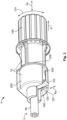
- a flying (plug-in) connector device 10 for a waterproof electrical (mini) connector 1 comprises ( Figure 3 ) a (mini) connection housing 100 with a sealing chamber 110 which is open at an end side edge 101 which is to the rear in the axial direction Ax of the connector device 10, and a protective cover 200, by means of which the open sealing chamber 110 can be at least partially covered at the rear.
- the sealing chamber 110 is delimited internally in the connection housing 100 by a shoulder 114 in an axial direction Ax opposite the rear end side edge 101, wherein a seal 112 which is preferably constructed as a cable seal 112 ( Figure 2 ) can be positioned, in particular can be axially supported Ax, at this shoulder 114.
- the cable seal 112 (see also Figures 5 , 11 and 12 ) seals an electrical cable 50 which extends through it, in particular a copper coaxial cable 50 and/or an aluminium coaxial cable 50, with respect to a contact chamber 160 of the connection housing 100, in which an electrical (mini) connector mechanism 60 of the cable 50 is or can be engaged.
- the connector mechanism 60 has three mutually separate parts, in particular a ferrule (which can be crimped, optionally), a first contact device (which can be crimped, optionally) (for example, with a pin ( Figs. 2 , 5 , 11 ), stud, tab, socket contact portion ( Fig.
- a second contact device which can be crimped, optionally
- a shield contact portion Figures 2 , 5 , 11 , 12 ), etc.
- the protective cover 200 has an axially Ax rear end side edge 201 and an axially Ax front end side edge 203, wherein the protective cover 200 is open at the front end side edge 203 thereof and can be pushed, with this side at the front, onto the connection housing 100 over the rear end side edge 101 of the sealing chamber 110 and can preferably be engaged thereon (catch mechanisms 130, 230).
- the protective cover 200 is closed except for a cable recess 240.
- the protective cover 200 has the cable recess 240 which extends through the entire protective cover 200 in the axial direction Ax.
- the cable recess 240 is constructed as a radial recess 240 in such a manner that the protective cover 200 can be placed onto the cable 50 from the radial exterior Ra and can be pushed, in a chronological sequence, onto the connection housing 100 and can be engaged at that location.
- the seal 112 in the sealing chamber 110 of a completely assembled connector 1 would be axially Ax accessible from the exterior, which may result in problems with water-tightness of the connector 1 in the case of water which is sprayed from a corresponding direction.
- that position is covered by means of a sealing device 120 which is in the form of a sealing plate 120, a sealing tab 120, a sealing flap 120, etc.
- the sealing device 120 is connected in the first variant to the connection housing 100, in particular in the vicinity of the sealing chamber 110.
- a separate design of the sealing device 120 can be applied in another variant of the invention.
- the sealing device 120 is connected to or constructed with the connection housing 100 in a materially engaging manner or integrally.
- the sealing device 120 is preferably connected to the connection housing 100 via a hinge 122, in particular integrally by means of a film hinge 122. Preferably, this is carried out at a rear portion of the connection housing 10, in particular at the axially Ax rear end side edge 101 of the open sealing chamber 110.
- a pre-assembly state ( Fig. 1 ) of the sealing device 120 on the connection housing 10 initially the hinge 122 and then, adjoining it in a radially Ra outward direction, the sealing device 120 extend away from the connection housing 10 from a radially Ra inner side towards a radially Ra exterior.
- a substantially planar extent of the hinge 122 and/or a substantially planar extent of the sealing device 120 it is preferable for a substantially planar extent of the hinge 122 and/or a substantially planar extent of the sealing device 120 to be located in a radial plane Ra (a radial plane Ra extends in this instance exclusively in the radial directions Ra) of the connection housing 10.
- the sealing device 120 can thereby be readily folded onto the sealing chamber 110 and/or readily folded into the sealing chamber 110.
- Figure 2 shows an assembly state of the sealing device 120 at/in the sealing chamber 110, wherein the protective cover 200 still remains in a pre-assembly state.
- the sealing device 120 is folded onto/into the sealing chamber 110.
- a substantially circular or cylindrical outer periphery of the sealing device 120 is further received in a substantially positive-locking manner at/in the sealing chamber 110.
- the sealing device 120 has a cable recess 124 which extends through the entire sealing device 120 in an axial direction Ax.
- the cable recess 124 is further constructed as a radial recess 124 in such a manner that the sealing device 120 can be pushed over the cable 50 from a radially Ra exterior and can be received, in a chronological sequence, at/in the sealing chamber 110.
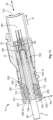
- the protective cover 200 can be assembled on the connection housing 100, the final assembly position of which is illustrated in Figure 3 . In this instance, the hinge 122 which is folded over through approximately 180° can be clearly seen.
- the cable recess 124 of the sealing device 120 and the cable recess 240 of the protective cover 200 constitute at a rear longitudinal end or longitudinal end portion of the connection housing 100 the cable bushing 124, 240.
- the protective cover 200 and the sealing device 120 in this case terminate the sealing chamber axially Ax towards the rear (rear end side edge 101 of the sealing chamber 110) in a substantially light-impermeable manner, except for the cable bushing 124, 240 which is formed by the two cable recesses 124, 240 being placed one above the other. If the cable 50 is received in the cable bushing 124, 240, a gap between the cable 50 and the cable bushing 124, 240 is preferably also formed in a substantially light-impermeable manner depending on a selected tolerance.
- the axially Ax rear end side edge 101 of the sealing chamber 110 has a recess 102 (see also Figure 1 ) for the hinge 122.
- a portion of the hinge 122, which portion can be or is folded over, can be received ( Figure 1 ) or is received ( Figures 2 and 3 ) in this recess 102, preferably in a positive-locking manner in a peripheral direction Um or transverse direction of the connector device 10.
- the cable recess 240 in the protective cover 200 can be used to receive a folded-over (double) portion of the hinge 122 in the assembly state of the protective cover 200 ( Figure 3 ).
- the hinge 122 and also the sealing device 220 it is preferable for the hinge 122 and also the sealing device 220 to extend away from the connection housing 100 in the pre-assembly state in a central/radial manner.
- the connector device 10 is constructed as a pin connector device 10 (pin connector mechanism 60); naturally, it is possible to construct the connector device 10 differently (see below).
- the cable recess 124 of the sealing device 120 and the cable recess 240 of the protective cover 200 overlap each other only in an axial Ax central region of the connector device 10, in which the cable 50 can be provided.
- the radial Ra courses of the cable recesses 124, 240 to the exterior are arranged so as to be radially Ra offset relative to each other in this case, that is to say, the two cable recesses 124, 240 are provided so as to be rotated relative to each other radially Ra at an angle. In this case, an approximately 180° angle is preferred, but with other angles which have to be different from 0° being able to be used. That is to say, if a comparatively small angle greater than 0° is intended to be used, a width of the cable recesses 124, 240 has to be taken into consideration. Furthermore, all angles can be used.
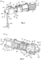
- the second variant of the invention as shown in Figs. 4 to 6 is constructed similarly to the first variant, wherein only differences from the first variant are explained below.
- a sealing device 220 is connected to the protective cover 200.
- the sealing device 220 is connected or constructed in a materially engaging manner or integrally with the protective cover 200.
- the sealing device 220 is preferably connected to the protective cover 200 via a hinge 222, in particular integrally by means of a film hinge 222.
- a cable recess 224 of the sealing device 220 of the protective cover 200 is in this instance constructed similarly to the cable recess 124 of the sealing device 120 of the connection housing 100.
- This is preferably carried out at a rear portion of the protective cover 200, in particular at an axially Ax rear end side edge 201 of the protective cover 200. It is also possible to connect the sealing device 220 to a central portion or to an axially Ax front end side edge 203 of the protective cover 200.
- a pre-assembly state ( Figure 4 ) of the sealing device 220 on the protective cover 200 initially the hinge 222 and, adjoining it in a radially Ra outward direction, the sealing device 220 extend away from the protective cover 200 from a radially Ra inner side towards a radially Ra exterior. In this case, it is preferable for the hinge 222 to be connected to the protective cover 200 laterally at the cable recess 240.
- a planar side of the hinge 222 is aligned with a rear end side, in particular a rear radial plane Ra, of the protective cover 200.
- the hinge 222 is positioned in a peripheral direction Um of the protective cover 200, preferably beside the cable recess 240, and is therefore eccentrically positioned. So that the sealing device 220 can be folded onto and/or into the sealing chamber 110 in a comfortable manner, the hinge 222 compensates for this eccentricity, preferably by means of the physical construction thereof, which can clearly be seen in Figure 5 .
- the hinge 222 does not have in the pre-assembly state of the sealing device 220 any substantially exclusively radial Ra course, as in the first variant, but instead further has an offset in the peripheral direction Um.
- an axially Ax extending portion of the hinge 222 has an offset in a peripheral direction Um or transverse direction. At a time during or after assembly of the protective cover 200, a projecting portion of the hinge 222 can be broken away.
- connection housing 100 and a contact-securing member 16 which can be provided or fixed therein (primary or secondary engagement) are preferably constructed in a substantially identical manner.
- a contact-securing member 16 for example, a retainer 16 serves to fix, in particular engage, the connector mechanism 60 in the connection housing 100, wherein the contact-securing member 16 itself is fixed, in particular engaged, at/in the connection housing 100.
- Fig. 1 and 2 and Fig. 4 and 5 show the mutually corresponding catch mechanisms 130, 230, by means of which the protective cover 200 can be fixed on/at the connection housing 100.
- Figures 7 to 12 show two additional embodiments of the first variant of the invention, wherein Figure 7 illustrates a flying (mini) socket connection housing 100 with a sealing device 120 according to the invention in a pre-assembly state (production state), Figure 8 illustrates a waterproof, flying electrical (mini) socket connector 1 during the final assembly thereof, Figure 9 illustrates a flying (mini) pin connection housing 100 with a sealing device 120 according to the invention in a pre-assembly state (production state) and Figure 10 illustrates a waterproof flying electrical (mini) pin connector 1 with an enclosure housing 12 during the final assembly thereof.
- Figure 11 shows the completely assembled pin connector 1 from Figure 10
- Figure 12 shows the completely assembled socket connector 1 from Figure 8 , each sectioned centrally in an axial direction Ax.
- FIGs. 9, 10 and 11 clearly show that the connector device 10 or the connection housing 100 of the connector device 10 does not have to be constructed as a single housing 10, 12; 100, 12 of the connector 1. It is possible to place the connector device 10 or the connection housing 100 in an enclosure housing 12. In this instance, the enclosure housing 12 can where applicable be constructed as an adapter. Furthermore, Figures 11 and 12 each show an inner seal 152 which is preferably constructed as a housing seal 152. In this instance, the seal 152 of Figure 11 seals between the connection housing 100 and the enclosure housing 12. The seal 152 of Figure 12 seals the inner chambers of the two connectors 1, 1 of Figures 11 and 12 with respect to each other when they are plugged together.
- a cable 50 which is provided only with a connector mechanism 60 can be referred to as a pre-assembled cable 5, whereas the cable 50 or the pre-assembled cable 5 can be referred to as a completely assembled cable 5 if the connector mechanism 60 is further provided, in particular engaged, in a contact chamber 160 (including a folded-in sealing device 120, 220 and an assembled protective cover 200). That is to say, the completely assembled cable 5 comprises the pre-assembled cable 5 with an assembled connector 1.
- a connector 1 (not assembled) can again comprise a connector device 10 with a connection housing 100 and a protective cover 200, where applicable including a connector mechanism 60, wherein the connection housing 100 can have an enclosure housing 12 ( Figures 10 and 11 ).
- the electrical connector 1 (with a connector device 10 or connection housing 100 and protective cover 200, where applicable with an enclosure housing 12, and/or another device and/or mechanism) can further comprise the seal 112, the seal 152, the connector mechanism 60 (without a cable 50), the connector mechanism 60 and, in a manner separate therefrom, the cable 50 and/or the (pre- /completely) assembled cable 5.
- An electrical (plug-in) connection according to the invention comprising a connector 1 and a mating connector 1 is then produced by assembling the two connectors 1, 1, for example, the ones shown in Figure 11 (connector 1 or mating connector 1) and in Figure 12 (mating connector 1 or connector 1).
- the four connectors 1 illustrated are constructed in this instance as coaxial plug-in connectors 1.
- the invention is used on a connector (1) which is constructed in accordance with the FAKRA standard (FAKRA: ausnik Automobil/automotive technical group), which applies in particular to RF (RF: radio frequency) or HF plug-in connections (HF: high frequency) in the automotive sector.
- FAKRA austig Automobil/automotive technical group
- RF radio frequency
- HF plug-in connections HF: high frequency
Claims (13)
- Verbindervorrichtung (10) für einen wasserdichten Verbinder (1) für ein Kabel (50), bevorzugt ein Koaxialkabel (50), insbesondere ein Kupferkabel (50) und/oder ein Aluminiumkabel (50) für den Kraftfahrzeugbereich, miteinem Verbindungsgehäuse (100) und einer Schutzkappe (200), wobei das Verbindungsgehäuse (100) einen Dichtungsraum (110) für eine Dichtung (112) umfasst, wobei der Dichtungsraum (110) von der Schutzkappe (200) abdeckbar ist, wobeidie Verbindervorrichtung (10) ferner eine Dichtungsvorrichtung (120, 220) aufweist, wobei die Dichtungsvorrichtung (120, 220) am/im Dichtungsraum (110) der Dichtung (112) jeweils direkt zueinander benachbart und/oder gestaffelt angeordnet werden kann, wobei die Dichtung (112) im Dichtungsraum (110) vorsehbar ist, wobeidie Dichtungsvorrichtung (120, 220) mit dem Verbindungsgehäuse (100) oder der Schutzkappe (200) mittels eines Scharniers (122, 222), insbesondere eines Filmscharniers (122, 222), mechanisch angebunden ist, dadurch gekennzeichnet, dassdie Dichtungsvorrichtung (120, 220) einstückig, stofflich einstückig oder integral mit dem Verbindungsgehäuse (100) oder der Schutzkappe (200) ausgebildet ist.
- Verbindervorrichtung (10) nach dem vorhergehenden Anspruch, dadurch gekennzeichnet, dass das Verbindungsgehäuse (100) und die Dichtungsvorrichtung (120 , 220) derart ausgebildet sind, dassdie Dichtungsvorrichtung (120, 220) am/im Dichtungsraum (110) in einer ersten Näherung im Wesentlichen formschlüssig aufnehmbar ist und/oderdas Scharnier (122, 222) in einer Ausnehmung (102) eines Stirnseitenrands (101) des Dichtungsraums (110) bevorzugt im Wesentlichen formschlüssig aufnehmbar ist.
- Verbindervorrichtung (10) nach einem der vorhergehenden Ansprüche, dadurch gekennzeichnet, dass neben der Dichtung (112), die Dichtungsvorrichtung (120, 220) in eine Axialrichtung (Ax) der Verbindervorrichtung (10) im Wesentlichen vollständig im Dichtungsraum (110) aufnehmbar ist.
- Verbindervorrichtung (10) nach einem der vorhergehenden Ansprüche, dadurch gekennzeichnet, dass in einem Montagezustand der Dichtungsvorrichtung (120, 220) und der Schutzkappe (200) am Verbindungsgehäuse (100), abgesehen von einer Kabeldurchführung (124/224, 240) der Verbindervorrichtung (10), die Verbindervorrichtung (10) in Axialrichtung (Ax) im Wesentlichen lichtdicht ausgebildet ist, und/oder
im Montagezustand der Dichtungsvorrichtung (120, 220) und der Schutzkappe (200) am Verbindungsgehäuse (100), sich eine Kabelausnehmung (124, 224) der Dichtungsvorrichtung (120, 220) und eine Kabelausnehmung (240) der Schutzkappe (200) als Kabeldurchführung (124/224, 240) in einer Radialrichtung (Ra) der Verbindervorrichtung (10) überlappen. - Verbindervorrichtung (10) nach einem der vorhergehenden Ansprüche, dadurch gekennzeichnet, dass in einem Vormontagezustand der Dichtungsvorrichtung (120, 220), die Dichtungsvorrichtung (120, 220) vom Verbindungsgehäuse (100) oder der Schutzkappe (200) wegsteht, und/oder
für einen Montagezustand der Dichtungsvorrichtung (120, 220) am/im Dichtungsraum (110), die Dichtungsvorrichtung (120, 220) an/in den Dichtungsraum (110) heranklappbar und/oder in den Dichtungsraum (110) hineinklappbar ist. - Verbindervorrichtung (10) nach einem der vorhergehenden Ansprüche, dadurch gekennzeichnet, dass die Dichtungsvorrichtung (120) an das Verbindungsgehäuse (100) mechanisch angebunden ist und die Dichtungsvorrichtung (120) bevorzugt radial nach außen vom Stirnseitenrand (101) des Dichtungsraums (110) wegsteht, oder
die Dichtungsvorrichtung (220) an die Schutzkappe (200) mechanisch angebunden ist und die Dichtungsvorrichtung (220) bevorzugt radial nach außen von einem in Axialrichtung (Ax) vorderen Stirnseitenrand (203) der Schutzkappe (200) oder einem in Axialrichtung (Ax) hinteren Stirnseitenrand (201) der Schutzkappe (200) wegsteht. - Verbindervorrichtung (10) nach einem der vorhergehenden Ansprüche, dadurch gekennzeichnet, dass die Verbindervorrichtung (10) derart ausgebildet ist, dass der im Dichtungsraum (110) einrichtbaren Dichtung (112) mittels der Schutzkappe (200) und der Dichtungsvorrichtung (120, 220) eine mechanische Vorspankraft aufprägbar ist.
- Verbindervorrichtung (10) nach einem der vorhergehenden Ansprüche, dadurch gekennzeichnet, dass:• das Verbindungsgehäuse (100) den Dichtungsraum (110) kabelabgangsseitig aufweist,• die Kabelausnehmung (124, 224) der Dichtungsvorrichtung (120, 220) als eine Radialausnehmung (124, 224) ausgebildet ist und/oder• die Kabelausnehmung (240) der Schutzkappe (200) als eine Radialausnehmung (240) ausgebildet ist.
- Wasserdichter Verbinder (1) für ein Kabel (50), bevorzugt ein Koaxialkabel (50), insbesondere ein Kupferkabel (50) und/oder ein Aluminiumkabel (50) für den Kraftfahrzeugbereich, dadurch gekennzeichnet, dass
der wasserdichte Verbinder (1) eine Verbindervorrichtung (10) nach einem der vorhergehenden Ansprüche aufweist. - Wasserdichter Verbinder (1) nach dem vorhergehenden Anspruch, dadurch gekennzeichnet, dass der Verbinder (1) im Dichtungsraum (110) eine Dichtung (112), insbesondere eine Kabeldichtung (112), aufweist, wobei die Dichtung (112), die Dichtungsvorrichtung (120, 220) und die Schutzkappe (200) jeweils direkt zueinander benachbart und/oder gestaffelt angeordnet sind.
- Wasserdichter Verbinder (1) nach einem der vorhergehenden Ansprüche, dadurch gekennzeichnet, dass die Schutzkappe (200) in Axialrichtung (Ax) eine mechanische Vorspannkraft über die Dichtungsvorrichtung (120, 220) auf die Dichtung (112) ausübt.
- Konfektioniertes elektrisches Kabel (5), bevorzugt konfektioniertes elektrisches Kupferkoaxialkabel (5) und/oder Aluminiumkoaxialkabel (5) für den Kraftfahrzeugbereich, dadurch gekennzeichnet, dass
das konfektionierte Kabel (5) eine Verbindervorrichtung (10) nach einem der Ansprüche 1 bis 8 oder einen wasserdichten elektrischen Verbinder (1) nach einem der Ansprüche 9 bis 11 aufweist. - Mechanismus, Modul, Gerät, Apparat, Anlage oder System, insbesondere für den Kraftfahrzeugbereich, dadurch gekennzeichnet, dass
der Mechanismus, das Modul, das Gerät, der Apparat, die Anlage oder das System eine Verbindervorrichtung (10) nach einem der Ansprüche 1 bis 8, einen wasserdichten Verbinder (1) nach einem der Ansprüche 9 bis 11 oder ein konfektioniertes elektrisches Kabel (5) nach dem vorhergehenden Anspruch aufweist.
Applications Claiming Priority (1)
| Application Number | Priority Date | Filing Date | Title |
|---|---|---|---|
| DE102016104992.1A DE102016104992A1 (de) | 2016-03-17 | 2016-03-17 | Verbindervorrichtung für einen wasserdichten Verbinder, wasserdichter Verbinder sowie konfektioniertes Kabel |
Publications (2)
| Publication Number | Publication Date |
|---|---|
| EP3220487A1 EP3220487A1 (de) | 2017-09-20 |
| EP3220487B1 true EP3220487B1 (de) | 2023-04-26 |
Family
ID=58347297
Family Applications (1)
| Application Number | Title | Priority Date | Filing Date |
|---|---|---|---|
| EP17161385.4A Active EP3220487B1 (de) | 2016-03-17 | 2017-03-16 | Verbindervorrichtung für einen wasserfesten verbinder, wasserdichter verbinder sowie konfektioniertes kabel |
Country Status (5)
| Country | Link |
|---|---|
| US (1) | US9985381B2 (de) |
| EP (1) | EP3220487B1 (de) |
| JP (1) | JP7161839B2 (de) |
| CN (1) | CN107204535B (de) |
| DE (1) | DE102016104992A1 (de) |
Families Citing this family (3)
| Publication number | Priority date | Publication date | Assignee | Title |
|---|---|---|---|---|
| US10116085B1 (en) * | 2018-05-08 | 2018-10-30 | Delphi Technologies, Inc. | Sealed connector with an extended seal sleeve and retainer |
| CN109103683B (zh) * | 2018-08-29 | 2023-11-17 | 江苏亨鑫科技有限公司 | 弯式同轴电缆防护装置 |
| CN112673530B (zh) * | 2018-09-11 | 2023-02-28 | 麦格纳国际公司 | 具有环境和电气保护的连接器装置 |
Family Cites Families (23)
| Publication number | Priority date | Publication date | Assignee | Title |
|---|---|---|---|---|
| US3633150A (en) * | 1970-04-08 | 1972-01-04 | Edward Swartz | Watertight electric receptacle connector |
| EP0072104B1 (de) * | 1981-07-23 | 1986-01-02 | AMP INCORPORATED (a New Jersey corporation) | Abgedichteter elektrischer Verbinder |
| JPH067584Y2 (ja) * | 1989-05-31 | 1994-02-23 | 矢崎総業株式会社 | 防水形コネクタ |
| JP2813620B2 (ja) * | 1993-08-06 | 1998-10-22 | 矢崎総業株式会社 | 防水コネクタ |
| JP2733894B2 (ja) * | 1993-10-25 | 1998-03-30 | 矢崎総業株式会社 | 防水コネクターのリアホルダカバー |
| EP0677894B1 (de) * | 1994-04-13 | 2001-09-05 | Sumitomo Wiring Systems, Ltd. | Abdichtungsvorrichtung und Herstellverfahren eines wasserdichten Stecker |
| JPH08138795A (ja) * | 1994-11-14 | 1996-05-31 | Kansei Corp | 防水コネクタ |
| JPH1012317A (ja) * | 1996-06-17 | 1998-01-16 | Yazaki Corp | 防水コネクタ |
| JP3530042B2 (ja) | 1998-09-30 | 2004-05-24 | 矢崎総業株式会社 | コネクタ |
| JP2000133367A (ja) * | 1998-10-20 | 2000-05-12 | Yazaki Corp | 防水コネクタ及び該防水コネクタの組付方法 |
| JP2000208200A (ja) * | 1999-01-13 | 2000-07-28 | Yazaki Corp | 防水コネクタ |
| JP2001052804A (ja) * | 1999-08-03 | 2001-02-23 | Yazaki Corp | 防水コネクタ及び該防水コネクタの組付方法 |
| JP2001110504A (ja) * | 1999-10-13 | 2001-04-20 | Yazaki Corp | 防水コネクタ |
| US6485332B1 (en) * | 2000-07-18 | 2002-11-26 | Yazaki North America | System for reconfiguring connector cover and seal |
| SG127773A1 (en) * | 2005-06-01 | 2006-12-29 | Mea Technologies Pte Ltd | Waterproof connector |
| US7465185B2 (en) * | 2006-03-30 | 2008-12-16 | Fci Americas Technology, Inc | Electrical connector assembly with mate-assist and a wire dress cover |
| US7371115B1 (en) * | 2006-12-15 | 2008-05-13 | Delphi Technologies, Inc. | Mat seal device |
| US8109789B2 (en) * | 2008-12-12 | 2012-02-07 | Tyco Electronics Corporation | Connector assembly with strain relief |
| FR2953071B1 (fr) * | 2009-11-23 | 2012-04-20 | Tyco Electronics France Sas | Boitier de connecteur electrique |
| JP5625793B2 (ja) * | 2010-11-18 | 2014-11-19 | 住友電装株式会社 | 防水コネクタ |
| EP2761708B1 (de) * | 2011-09-29 | 2018-07-04 | Schleuniger Holding AG | Verfahren zur bestückung eines kabels mit seals und dazugehörige sealbestückungsstation |
| CN105305154B (zh) * | 2014-07-29 | 2017-08-08 | 中国船舶重工集团公司第七二二研究所 | 一种深水电连接装置及深水电缆组件 |
| CN204740878U (zh) * | 2015-06-19 | 2015-11-04 | 四川九洲线缆有限责任公司 | 一种防水型装备用多芯分支电缆组件 |
-
2016
- 2016-03-17 DE DE102016104992.1A patent/DE102016104992A1/de active Pending
-
2017
- 2017-03-16 JP JP2017050803A patent/JP7161839B2/ja active Active
- 2017-03-16 EP EP17161385.4A patent/EP3220487B1/de active Active
- 2017-03-17 US US15/462,453 patent/US9985381B2/en active Active
- 2017-03-17 CN CN201710161751.5A patent/CN107204535B/zh active Active
Also Published As
| Publication number | Publication date |
|---|---|
| CN107204535A (zh) | 2017-09-26 |
| JP7161839B2 (ja) | 2022-10-27 |
| US9985381B2 (en) | 2018-05-29 |
| DE102016104992A1 (de) | 2017-09-21 |
| EP3220487A1 (de) | 2017-09-20 |
| US20170271810A1 (en) | 2017-09-21 |
| CN107204535B (zh) | 2021-02-05 |
| JP2017168444A (ja) | 2017-09-21 |
Similar Documents
| Publication | Publication Date | Title |
|---|---|---|
| US10256565B2 (en) | Power-electric contact device; exchangeable power-electric contact module as well as power-electric connector | |
| EP3276752B1 (de) | Koaxialverbinderanordnung | |
| US9929491B2 (en) | Live portion protection structure and connector | |
| JP6543731B2 (ja) | 充電コネクタ及び充電コネクタ組立体の製造方法 | |
| EP2483971B1 (de) | Zweiteiliges kontaktelement für hochspannungssteckanschluss | |
| JP6222751B2 (ja) | ヘッダーアセンブリ | |
| EP2127039B1 (de) | Abgeschirmte hochspannungs-elektrosteckeranordnung | |
| EP3166186B1 (de) | Elektromagnetischer abgeschirmter steckverbinder | |
| EP3220487B1 (de) | Verbindervorrichtung für einen wasserfesten verbinder, wasserdichter verbinder sowie konfektioniertes kabel | |
| JP2008508689A (ja) | 電気プラグ及びその取付け方法 | |
| KR20190034116A (ko) | 전기 콘택 디바이스, 전기 연결 유닛 및 전기 케이블 조립하기 위한 방법 | |
| KR20170089865A (ko) | 자동차용 카메라 및 자동차 | |
| US10873153B2 (en) | Plug-in connector | |
| CN111200204B (zh) | 连接器 | |
| EP3944424A1 (de) | Elektrische steckverbindung und elektrischer verbinder | |
| WO2019170558A1 (en) | Sealing unit for a conductor and electrical connector | |
| KR101496574B1 (ko) | 자동차 분야에서 고전압 전류를 전송하기 위한 연결 장치 | |
| US20220200193A1 (en) | Battery connector for electric bicycle | |
| CN106030919B (zh) | 插接连接装置 | |
| CN114267977A (zh) | 具有最小扭转载荷传递的电连接器 | |
| KR20170072756A (ko) | 커넥터 | |
| US8814597B2 (en) | Electrical plug contact | |
| US20240063584A1 (en) | Electrical High-Current Connector | |
| JP2019186022A (ja) | 防水カバー及びこれを備えた充電コネクタ | |
| EP4075603A1 (de) | Elektrische quetschhülse, verfahren zur montage einer hülse und verfahren zur anordnung einer elektrischen verbindungsvorrichtung |
Legal Events
| Date | Code | Title | Description |
|---|---|---|---|
| PUAI | Public reference made under article 153(3) epc to a published international application that has entered the european phase |
Free format text: ORIGINAL CODE: 0009012 |
|
| STAA | Information on the status of an ep patent application or granted ep patent |
Free format text: STATUS: THE APPLICATION HAS BEEN PUBLISHED |
|
| AK | Designated contracting states |
Kind code of ref document: A1 Designated state(s): AL AT BE BG CH CY CZ DE DK EE ES FI FR GB GR HR HU IE IS IT LI LT LU LV MC MK MT NL NO PL PT RO RS SE SI SK SM TR |
|
| AX | Request for extension of the european patent |
Extension state: BA ME |
|
| STAA | Information on the status of an ep patent application or granted ep patent |
Free format text: STATUS: REQUEST FOR EXAMINATION WAS MADE |
|
| 17P | Request for examination filed |
Effective date: 20180320 |
|
| RBV | Designated contracting states (corrected) |
Designated state(s): AL AT BE BG CH CY CZ DE DK EE ES FI FR GB GR HR HU IE IS IT LI LT LU LV MC MK MT NL NO PL PT RO RS SE SI SK SM TR |
|
| STAA | Information on the status of an ep patent application or granted ep patent |
Free format text: STATUS: EXAMINATION IS IN PROGRESS |
|
| 17Q | First examination report despatched |
Effective date: 20190225 |
|
| STAA | Information on the status of an ep patent application or granted ep patent |
Free format text: STATUS: EXAMINATION IS IN PROGRESS |
|
| STAA | Information on the status of an ep patent application or granted ep patent |
Free format text: STATUS: EXAMINATION IS IN PROGRESS |
|
| GRAP | Despatch of communication of intention to grant a patent |
Free format text: ORIGINAL CODE: EPIDOSNIGR1 |
|
| STAA | Information on the status of an ep patent application or granted ep patent |
Free format text: STATUS: GRANT OF PATENT IS INTENDED |
|
| INTG | Intention to grant announced |
Effective date: 20221123 |
|
| GRAS | Grant fee paid |
Free format text: ORIGINAL CODE: EPIDOSNIGR3 |
|
| GRAA | (expected) grant |
Free format text: ORIGINAL CODE: 0009210 |
|
| STAA | Information on the status of an ep patent application or granted ep patent |
Free format text: STATUS: THE PATENT HAS BEEN GRANTED |
|
| AK | Designated contracting states |
Kind code of ref document: B1 Designated state(s): AL AT BE BG CH CY CZ DE DK EE ES FI FR GB GR HR HU IE IS IT LI LT LU LV MC MK MT NL NO PL PT RO RS SE SI SK SM TR |
|
| REG | Reference to a national code |
Ref country code: GB Ref legal event code: FG4D |
|
| REG | Reference to a national code |
Ref country code: CH Ref legal event code: EP |
|
| REG | Reference to a national code |
Ref country code: DE Ref legal event code: R096 Ref document number: 602017068008 Country of ref document: DE |
|
| REG | Reference to a national code |
Ref country code: AT Ref legal event code: REF Ref document number: 1563520 Country of ref document: AT Kind code of ref document: T Effective date: 20230515 |
|
| REG | Reference to a national code |
Ref country code: IE Ref legal event code: FG4D |
|
| REG | Reference to a national code |
Ref country code: LT Ref legal event code: MG9D |
|
| REG | Reference to a national code |
Ref country code: NL Ref legal event code: MP Effective date: 20230426 |
|
| REG | Reference to a national code |
Ref country code: AT Ref legal event code: MK05 Ref document number: 1563520 Country of ref document: AT Kind code of ref document: T Effective date: 20230426 |
|
| PG25 | Lapsed in a contracting state [announced via postgrant information from national office to epo] |
Ref country code: NL Free format text: LAPSE BECAUSE OF FAILURE TO SUBMIT A TRANSLATION OF THE DESCRIPTION OR TO PAY THE FEE WITHIN THE PRESCRIBED TIME-LIMIT Effective date: 20230426 |
|
| PG25 | Lapsed in a contracting state [announced via postgrant information from national office to epo] |
Ref country code: SE Free format text: LAPSE BECAUSE OF FAILURE TO SUBMIT A TRANSLATION OF THE DESCRIPTION OR TO PAY THE FEE WITHIN THE PRESCRIBED TIME-LIMIT Effective date: 20230426 Ref country code: PT Free format text: LAPSE BECAUSE OF FAILURE TO SUBMIT A TRANSLATION OF THE DESCRIPTION OR TO PAY THE FEE WITHIN THE PRESCRIBED TIME-LIMIT Effective date: 20230828 Ref country code: NO Free format text: LAPSE BECAUSE OF FAILURE TO SUBMIT A TRANSLATION OF THE DESCRIPTION OR TO PAY THE FEE WITHIN THE PRESCRIBED TIME-LIMIT Effective date: 20230726 Ref country code: ES Free format text: LAPSE BECAUSE OF FAILURE TO SUBMIT A TRANSLATION OF THE DESCRIPTION OR TO PAY THE FEE WITHIN THE PRESCRIBED TIME-LIMIT Effective date: 20230426 Ref country code: AT Free format text: LAPSE BECAUSE OF FAILURE TO SUBMIT A TRANSLATION OF THE DESCRIPTION OR TO PAY THE FEE WITHIN THE PRESCRIBED TIME-LIMIT Effective date: 20230426 |
|
| PG25 | Lapsed in a contracting state [announced via postgrant information from national office to epo] |
Ref country code: RS Free format text: LAPSE BECAUSE OF FAILURE TO SUBMIT A TRANSLATION OF THE DESCRIPTION OR TO PAY THE FEE WITHIN THE PRESCRIBED TIME-LIMIT Effective date: 20230426 Ref country code: PL Free format text: LAPSE BECAUSE OF FAILURE TO SUBMIT A TRANSLATION OF THE DESCRIPTION OR TO PAY THE FEE WITHIN THE PRESCRIBED TIME-LIMIT Effective date: 20230426 Ref country code: LV Free format text: LAPSE BECAUSE OF FAILURE TO SUBMIT A TRANSLATION OF THE DESCRIPTION OR TO PAY THE FEE WITHIN THE PRESCRIBED TIME-LIMIT Effective date: 20230426 Ref country code: LT Free format text: LAPSE BECAUSE OF FAILURE TO SUBMIT A TRANSLATION OF THE DESCRIPTION OR TO PAY THE FEE WITHIN THE PRESCRIBED TIME-LIMIT Effective date: 20230426 Ref country code: IS Free format text: LAPSE BECAUSE OF FAILURE TO SUBMIT A TRANSLATION OF THE DESCRIPTION OR TO PAY THE FEE WITHIN THE PRESCRIBED TIME-LIMIT Effective date: 20230826 Ref country code: HR Free format text: LAPSE BECAUSE OF FAILURE TO SUBMIT A TRANSLATION OF THE DESCRIPTION OR TO PAY THE FEE WITHIN THE PRESCRIBED TIME-LIMIT Effective date: 20230426 Ref country code: GR Free format text: LAPSE BECAUSE OF FAILURE TO SUBMIT A TRANSLATION OF THE DESCRIPTION OR TO PAY THE FEE WITHIN THE PRESCRIBED TIME-LIMIT Effective date: 20230727 |
|
| PG25 | Lapsed in a contracting state [announced via postgrant information from national office to epo] |
Ref country code: FI Free format text: LAPSE BECAUSE OF FAILURE TO SUBMIT A TRANSLATION OF THE DESCRIPTION OR TO PAY THE FEE WITHIN THE PRESCRIBED TIME-LIMIT Effective date: 20230426 |
|
| PG25 | Lapsed in a contracting state [announced via postgrant information from national office to epo] |
Ref country code: SK Free format text: LAPSE BECAUSE OF FAILURE TO SUBMIT A TRANSLATION OF THE DESCRIPTION OR TO PAY THE FEE WITHIN THE PRESCRIBED TIME-LIMIT Effective date: 20230426 |
|
| REG | Reference to a national code |
Ref country code: DE Ref legal event code: R097 Ref document number: 602017068008 Country of ref document: DE |
|
| PG25 | Lapsed in a contracting state [announced via postgrant information from national office to epo] |
Ref country code: SM Free format text: LAPSE BECAUSE OF FAILURE TO SUBMIT A TRANSLATION OF THE DESCRIPTION OR TO PAY THE FEE WITHIN THE PRESCRIBED TIME-LIMIT Effective date: 20230426 Ref country code: SK Free format text: LAPSE BECAUSE OF FAILURE TO SUBMIT A TRANSLATION OF THE DESCRIPTION OR TO PAY THE FEE WITHIN THE PRESCRIBED TIME-LIMIT Effective date: 20230426 Ref country code: RO Free format text: LAPSE BECAUSE OF FAILURE TO SUBMIT A TRANSLATION OF THE DESCRIPTION OR TO PAY THE FEE WITHIN THE PRESCRIBED TIME-LIMIT Effective date: 20230426 Ref country code: EE Free format text: LAPSE BECAUSE OF FAILURE TO SUBMIT A TRANSLATION OF THE DESCRIPTION OR TO PAY THE FEE WITHIN THE PRESCRIBED TIME-LIMIT Effective date: 20230426 Ref country code: DK Free format text: LAPSE BECAUSE OF FAILURE TO SUBMIT A TRANSLATION OF THE DESCRIPTION OR TO PAY THE FEE WITHIN THE PRESCRIBED TIME-LIMIT Effective date: 20230426 Ref country code: CZ Free format text: LAPSE BECAUSE OF FAILURE TO SUBMIT A TRANSLATION OF THE DESCRIPTION OR TO PAY THE FEE WITHIN THE PRESCRIBED TIME-LIMIT Effective date: 20230426 |
|
| PLBE | No opposition filed within time limit |
Free format text: ORIGINAL CODE: 0009261 |
|
| STAA | Information on the status of an ep patent application or granted ep patent |
Free format text: STATUS: NO OPPOSITION FILED WITHIN TIME LIMIT |
|
| 26N | No opposition filed |
Effective date: 20240129 |
|
| PG25 | Lapsed in a contracting state [announced via postgrant information from national office to epo] |
Ref country code: SI Free format text: LAPSE BECAUSE OF FAILURE TO SUBMIT A TRANSLATION OF THE DESCRIPTION OR TO PAY THE FEE WITHIN THE PRESCRIBED TIME-LIMIT Effective date: 20230426 |